EP3131192A1 - Dispositif de commande et procede de commande d'un composant relevant de la securite - Google Patents
Dispositif de commande et procede de commande d'un composant relevant de la securite Download PDFInfo
- Publication number
- EP3131192A1 EP3131192A1 EP15181147.8A EP15181147A EP3131192A1 EP 3131192 A1 EP3131192 A1 EP 3131192A1 EP 15181147 A EP15181147 A EP 15181147A EP 3131192 A1 EP3131192 A1 EP 3131192A1
- Authority
- EP
- European Patent Office
- Prior art keywords
- control device
- switching
- computers
- computer
- transformer
- Prior art date
- Legal status (The legal status is an assumption and is not a legal conclusion. Google has not performed a legal analysis and makes no representation as to the accuracy of the status listed.)
- Granted
Links
Images

Classifications
-
- H—ELECTRICITY
- H02—GENERATION; CONVERSION OR DISTRIBUTION OF ELECTRIC POWER
- H02M—APPARATUS FOR CONVERSION BETWEEN AC AND AC, BETWEEN AC AND DC, OR BETWEEN DC AND DC, AND FOR USE WITH MAINS OR SIMILAR POWER SUPPLY SYSTEMS; CONVERSION OF DC OR AC INPUT POWER INTO SURGE OUTPUT POWER; CONTROL OR REGULATION THEREOF
- H02M1/00—Details of apparatus for conversion
- H02M1/32—Means for protecting converters other than automatic disconnection
-
- B—PERFORMING OPERATIONS; TRANSPORTING
- B61—RAILWAYS
- B61L—GUIDING RAILWAY TRAFFIC; ENSURING THE SAFETY OF RAILWAY TRAFFIC
- B61L1/00—Devices along the route controlled by interaction with the vehicle or train
- B61L1/16—Devices for counting axles; Devices for counting vehicles
- B61L1/167—Circuit details
-
- B—PERFORMING OPERATIONS; TRANSPORTING
- B61—RAILWAYS
- B61L—GUIDING RAILWAY TRAFFIC; ENSURING THE SAFETY OF RAILWAY TRAFFIC
- B61L1/00—Devices along the route controlled by interaction with the vehicle or train
- B61L1/18—Railway track circuits
- B61L1/181—Details
-
- B—PERFORMING OPERATIONS; TRANSPORTING
- B61—RAILWAYS
- B61L—GUIDING RAILWAY TRAFFIC; ENSURING THE SAFETY OF RAILWAY TRAFFIC
- B61L29/00—Safety means for rail/road crossing traffic
- B61L29/24—Means for warning road traffic that a gate is closed or closing, or that rail traffic is approaching, e.g. for visible or audible warning
- B61L29/28—Means for warning road traffic that a gate is closed or closing, or that rail traffic is approaching, e.g. for visible or audible warning electrically operated
- B61L29/288—Wiring diagram of the signal control circuits
-
- B—PERFORMING OPERATIONS; TRANSPORTING
- B61—RAILWAYS
- B61L—GUIDING RAILWAY TRAFFIC; ENSURING THE SAFETY OF RAILWAY TRAFFIC
- B61L5/00—Local operating mechanisms for points or track-mounted scotch-blocks; Visible or audible signals; Local operating mechanisms for visible or audible signals
- B61L5/12—Visible signals
- B61L5/18—Light signals; Mechanisms associated therewith, e.g. blinders
- B61L5/1809—Daylight signals
- B61L5/1881—Wiring diagrams for power supply, control or testing
-
- B—PERFORMING OPERATIONS; TRANSPORTING
- B61—RAILWAYS
- B61L—GUIDING RAILWAY TRAFFIC; ENSURING THE SAFETY OF RAILWAY TRAFFIC
- B61L7/00—Remote control of local operating means for points, signals, or track-mounted scotch-blocks
- B61L7/06—Remote control of local operating means for points, signals, or track-mounted scotch-blocks using electrical transmission
- B61L7/08—Circuitry
-
- H—ELECTRICITY
- H02—GENERATION; CONVERSION OR DISTRIBUTION OF ELECTRIC POWER
- H02H—EMERGENCY PROTECTIVE CIRCUIT ARRANGEMENTS
- H02H7/00—Emergency protective circuit arrangements specially adapted for specific types of electric machines or apparatus or for sectionalised protection of cable or line systems, and effecting automatic switching in the event of an undesired change from normal working conditions
- H02H7/08—Emergency protective circuit arrangements specially adapted for specific types of electric machines or apparatus or for sectionalised protection of cable or line systems, and effecting automatic switching in the event of an undesired change from normal working conditions for dynamo-electric motors
- H02H7/0833—Emergency protective circuit arrangements specially adapted for specific types of electric machines or apparatus or for sectionalised protection of cable or line systems, and effecting automatic switching in the event of an undesired change from normal working conditions for dynamo-electric motors for electric motors with control arrangements
- H02H7/0844—Fail safe control, e.g. by comparing control signal and controlled current, isolating motor on commutation error
-
- H—ELECTRICITY
- H02—GENERATION; CONVERSION OR DISTRIBUTION OF ELECTRIC POWER
- H02M—APPARATUS FOR CONVERSION BETWEEN AC AND AC, BETWEEN AC AND DC, OR BETWEEN DC AND DC, AND FOR USE WITH MAINS OR SIMILAR POWER SUPPLY SYSTEMS; CONVERSION OF DC OR AC INPUT POWER INTO SURGE OUTPUT POWER; CONTROL OR REGULATION THEREOF
- H02M1/00—Details of apparatus for conversion
- H02M1/08—Circuits specially adapted for the generation of control voltages for semiconductor devices incorporated in static converters
- H02M1/084—Circuits specially adapted for the generation of control voltages for semiconductor devices incorporated in static converters using a control circuit common to several phases of a multi-phase system
-
- H—ELECTRICITY
- H02—GENERATION; CONVERSION OR DISTRIBUTION OF ELECTRIC POWER
- H02M—APPARATUS FOR CONVERSION BETWEEN AC AND AC, BETWEEN AC AND DC, OR BETWEEN DC AND DC, AND FOR USE WITH MAINS OR SIMILAR POWER SUPPLY SYSTEMS; CONVERSION OF DC OR AC INPUT POWER INTO SURGE OUTPUT POWER; CONTROL OR REGULATION THEREOF
- H02M3/00—Conversion of DC power input into DC power output
- H02M3/22—Conversion of DC power input into DC power output with intermediate conversion into AC
- H02M3/24—Conversion of DC power input into DC power output with intermediate conversion into AC by static converters
- H02M3/28—Conversion of DC power input into DC power output with intermediate conversion into AC by static converters using discharge tubes with control electrode or semiconductor devices with control electrode to produce the intermediate AC
- H02M3/325—Conversion of DC power input into DC power output with intermediate conversion into AC by static converters using discharge tubes with control electrode or semiconductor devices with control electrode to produce the intermediate AC using devices of a triode or a transistor type requiring continuous application of a control signal
- H02M3/335—Conversion of DC power input into DC power output with intermediate conversion into AC by static converters using discharge tubes with control electrode or semiconductor devices with control electrode to produce the intermediate AC using devices of a triode or a transistor type requiring continuous application of a control signal using semiconductor devices only
- H02M3/33569—Conversion of DC power input into DC power output with intermediate conversion into AC by static converters using discharge tubes with control electrode or semiconductor devices with control electrode to produce the intermediate AC using devices of a triode or a transistor type requiring continuous application of a control signal using semiconductor devices only having several active switching elements
- H02M3/33573—Full-bridge at primary side of an isolation transformer
Definitions
- the invention relates to a control device and a method for controlling a safety-relevant component.
- Out DE 3003291 C2 is a two-channel data processing arrangement with two same data processing microcontrollers known, each microcontroller controls a transformer.
- a clock signal converts a DC signal into an AC signal so that the signal can be transmitted through the first transformer.
- the second transformer can be switched by means of the second microcontroller.
- a data transfer takes place only if both microcontrollers give a switching signal to the respective transformer.
- a disadvantage of this arrangement is the high hardware requirements, in particular with regard to the transformers, which is associated with high costs, large space requirements and poor efficiency.
- axle counter (Az LM) from Thales Transportation Systems GmbH is known, which has a dual-channel control device with parallel relay interfaces.
- this device is susceptible to wear and vibration, whereby contacts of the relay can be solved.
- the control device comprises a transformer for outputting a control signal, an H-bridge circuit with two switching branches and a bridge branch, each switching branch comprising a switching element pair consisting of two series-connected switching elements and the bridge branch as load a primary coil of the transformer.
- the control device further comprises two independent, synchronized computers, each computer operating one of the switching element pairs by means of control elements, e.g. In the case of a switching command, the computers are arranged to alternately open and close the switching elements of each switching element pair at a predetermined frequency, so that the transformer is supplied with an alternating voltage of the predetermined frequency.
- the controls are controlled by the computers so that each time a switching element is opened in each switching element pair and a switching element is closed.
- the two computers are synchronized.
- further switching elements may be present in each switching branch, in particular in order to increase the availability (redundancy).
- Transformers have the indelible physical property that energy transfer occurs only when exposed to alternating current.
- the inventive control of the H-bridge (transistor bridge) generates an alternating voltage, whereby a control signal is output to the safety-relevant component to be controlled via the transformer.
- the transformer is jointly controlled by two computers (microcontrollers) independent of each other (in the sense of the standard DIN EN 50129 valid at the time of application), each computer controlling a voltage pole of the transformer. If one of the calculators no more switching command outputs, or one of the switch no longer switches, the current in the primary coil is no longer reversed and there is no energy transfer in the transformer more or the voltage output from the transformer drops to a very small value, causing a shutdown of the Current flow can be initiated by the control device. The control device thus makes itself ineffective and is thus transferred to a safe state. In this way, the SIL4 level required for railway safety components can be achieved.
- monitoring elements for monitoring the switching states of the switching elements are present.
- the monitoring elements detect a signal relating to the switching state of the respective switching element, which is transmitted to the associated computer (that is, the computer which is responsible for the control of the relevant switching element), so that it can be checked whether the switching element is working properly. This is generally done by comparing the switching state, which was determined on the basis of the transmitted signal, with a desired switching state, which is stored in the computer).
- a further development of this embodiment provides that the monitoring elements are each connected to both computers for transmitting a signal relating to the switching state of the respective switching element to both computers. This provides a way to synchronize the computers. The security can be further increased if one of the computer no longer issues switching commands as soon as it detects that the other computer no longer issues switching commands or no longer switch the switching elements assigned to it.
- the one of the computer controlled switching elements via lines, each with a resistor in safety design with the other computer connected are.
- the safety design guarantees that the resistance can only increase but not decrease in the event of a defect, so that a short circuit can be safely avoided.
- "Guaranteed” in this context means that the probability of a drag reduction is so extremely small that one considers this event to be excluded. This property of the device is considered captive as long as no overloading of the component occurs. The overload case must therefore be excluded by the circuit and dimensioning of the components.
- the monitoring elements are optocouplers, which are each connected in parallel to one of the switching elements.
- the switching elements can thereby be controlled electrically isolated from the corresponding computer.
- the two computers can be connected to each other via a data line.
- Information regarding the switching commands for switching the switching elements can thus be exchanged directly between the two computers (alternatively or additionally to the information transmission of the monitoring elements to both computers).
- the two computers are designed as a master-slave configuration.
- a galvanic separation between computers and switching elements can be realized, for example, that serve as controls optocouplers. Due to the inherent properties of the optocouplers computer and switching elements are galvanically separated from each other and data transmission can only be done in one direction. A manipulation of the data transmission direction in the microcontrollers by software can thus excluded. Alternatively, transformers can be used as controls.
- the transformer is followed by a rectifier.
- safety-related components can be operated with direct current.
- a "safe state” means a behavior of the technology which does not represent any danger to the operation (persons and material) and which is always attainable regardless of the error that has occurred.
- the invention is preferably used in the railway sector.
- the safety-relevant component can then be, for example, a signal lamp, a train detection system or a level crossing gate.
- the invention also relates to a method for controlling a safety-relevant component with a control device described above, wherein the computer of the control device in the case of an input switching command, the switching elements of each switching element pair alternately open and close in a predetermined frequency, so that the transformer with an AC voltage of predetermined frequency is supplied.
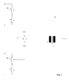
- Fig. 1 shows the basic configuration of the control device according to the invention.
- the control device comprises an H-bridge circuit with two switching branches SZ1, SZ2 and a bridge branch BZ.
- a switching element pair S1 / S2, S3 / S4 is arranged with two switching elements S1, S2, S3, S4 connected in series.
- the H bridge circuit is supplied with power via a DC voltage source, one switching element S1, S3 at the positive pole and the other switching element S2, S4 at each of each switching element pair S1 / S2, S3 / S4 Negative pole of the voltage source is connected.
- the switches S1, S2 of the first switching element pair S1 / S2 are controlled by a first computer MK1, the switches S3, S4 of the second switching element pair S3 / S4 by a second computer MK2 .
- a transformer T is supplied with AC voltage whose primary coil P is part of the bridge branch BZ of the H-bridge circuit (load).
- the two computers MK1, MK2 switch the switching elements S1, S2, S3, S4 so that either the switching elements S1 and S4 or the switching elements S2 and S3 are alternately closed together so that current flows through the primary coil P of the transformer T.
- the switching frequency of the switching elements and thus the AC voltage generated thereby is at least 1 kHz, preferably more than 50 kHz and is limited by the synchronization frequency and transformer properties, in particular inductance of the coils and hysteresis of the iron core.
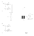
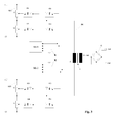
- the control of the switching elements S1, S2, S3, S4 is preferably carried out via optocouplers 01, 02, 03, 04, as in Fig. 2 shown, so that the computers are galvanically isolated from the switching elements.
- the transformer T a rectifier G downstream.
- the two computers MK1, MK2 are connected to each other via a data line L with a resistor R in safety construction and can be synchronized with each other.
- monitoring elements U1, U2, U3, U4 are provided, which may for example be designed as an optocoupler and for monitoring the switching states of the switching elements S1, S2, S3, S4 are used during operation. To do this detected by the monitoring elements U1, U2, U3, U4 switching state signals that are transmitted to the corresponding switching element controlling computer. Turning off a channel to test the operability of the corresponding channel is not necessary in this embodiment due to the cyclic changing of the states of all the switching elements.
- the switching state signals to the other computer ie the computer that is not responsible for the control of the corresponding switching element
- the first computer MK1 is connected to the monitoring elements U3, U4 and the second computer MK2 with the monitoring elements U1, U2 via one line with a resistor R1, R2 in safety design.
- the inventive alternating power supply of a transformer by means of an H-bridge circuit whose switching elements are controlled by two independent computers a simple and reliable control of safety-related components is realized, with a safe shutdown is guaranteed in case of failure of a switching element or a computer.
Landscapes
- Engineering & Computer Science (AREA)
- Mechanical Engineering (AREA)
- Power Engineering (AREA)
- Automation & Control Theory (AREA)
- Train Traffic Observation, Control, And Security (AREA)
- Safety Devices In Control Systems (AREA)
Priority Applications (4)
| Application Number | Priority Date | Filing Date | Title |
|---|---|---|---|
| EP15181147.8A EP3131192B1 (fr) | 2015-08-14 | 2015-08-14 | Dispositif de commande et procede de commande d'un composant relevant de la securite |
| DK15181147.8T DK3131192T3 (en) | 2015-08-14 | 2015-08-14 | Control device and method for controlling a safety-relevant component |
| ES15181147.8T ES2693090T3 (es) | 2015-08-14 | 2015-08-14 | Dispositivo de control y procedimiento para el control de un componente relevante para la seguridad |
| HRP20181750TT HRP20181750T1 (hr) | 2015-08-14 | 2018-10-24 | Upravljački uređaj i postupak za upravljanje sigurnosnim komponentama |
Applications Claiming Priority (1)
| Application Number | Priority Date | Filing Date | Title |
|---|---|---|---|
| EP15181147.8A EP3131192B1 (fr) | 2015-08-14 | 2015-08-14 | Dispositif de commande et procede de commande d'un composant relevant de la securite |
Publications (2)
| Publication Number | Publication Date |
|---|---|
| EP3131192A1 true EP3131192A1 (fr) | 2017-02-15 |
| EP3131192B1 EP3131192B1 (fr) | 2018-10-03 |
Family
ID=53879385
Family Applications (1)
| Application Number | Title | Priority Date | Filing Date |
|---|---|---|---|
| EP15181147.8A Active EP3131192B1 (fr) | 2015-08-14 | 2015-08-14 | Dispositif de commande et procede de commande d'un composant relevant de la securite |
Country Status (4)
| Country | Link |
|---|---|
| EP (1) | EP3131192B1 (fr) |
| DK (1) | DK3131192T3 (fr) |
| ES (1) | ES2693090T3 (fr) |
| HR (1) | HRP20181750T1 (fr) |
Citations (3)
| Publication number | Priority date | Publication date | Assignee | Title |
|---|---|---|---|---|
| DE3003291C2 (de) | 1980-01-30 | 1983-02-24 | Siemens AG, 1000 Berlin und 8000 München | Zweikanalige Datenverarbeitungsanordnung für Eisenbahnsicherungszwecke |
| WO2002015363A2 (fr) * | 2000-08-18 | 2002-02-21 | Hochschule Technik + Architektur Luzern | Installation d'accumulateurs de courant comprenant des batteries et des condensateurs, notamment des supercondensateurs |
| US8937822B2 (en) * | 2011-05-08 | 2015-01-20 | Paul Wilkinson Dent | Solar energy conversion and utilization system |
-
2015
- 2015-08-14 ES ES15181147.8T patent/ES2693090T3/es active Active
- 2015-08-14 DK DK15181147.8T patent/DK3131192T3/en active
- 2015-08-14 EP EP15181147.8A patent/EP3131192B1/fr active Active
-
2018
- 2018-10-24 HR HRP20181750TT patent/HRP20181750T1/hr unknown
Patent Citations (3)
| Publication number | Priority date | Publication date | Assignee | Title |
|---|---|---|---|---|
| DE3003291C2 (de) | 1980-01-30 | 1983-02-24 | Siemens AG, 1000 Berlin und 8000 München | Zweikanalige Datenverarbeitungsanordnung für Eisenbahnsicherungszwecke |
| WO2002015363A2 (fr) * | 2000-08-18 | 2002-02-21 | Hochschule Technik + Architektur Luzern | Installation d'accumulateurs de courant comprenant des batteries et des condensateurs, notamment des supercondensateurs |
| US8937822B2 (en) * | 2011-05-08 | 2015-01-20 | Paul Wilkinson Dent | Solar energy conversion and utilization system |
Also Published As
| Publication number | Publication date |
|---|---|
| EP3131192B1 (fr) | 2018-10-03 |
| ES2693090T3 (es) | 2018-12-07 |
| HRP20181750T1 (hr) | 2018-12-28 |
| DK3131192T3 (en) | 2018-12-03 |
Similar Documents
| Publication | Publication Date | Title |
|---|---|---|
| DE102012103015B4 (de) | Sicherheitsschaltvorrichtung mit Schaltelement im Hilfskontaktstrompfad | |
| EP1058093A1 (fr) | Procédé et circuit d'alimentation et de surveillance du fonctionnement d'au moins un capteur | |
| DE202012101654U1 (de) | Kompaktsteuergerät zum fehlersicheren Ansteuern eines elektrischen Aktors | |
| EP2587512B1 (fr) | Commutateur orienté vers la sécurité | |
| DE2711416C2 (de) | Anordnung zur Anzeige des Schaltungszustandes der Schalter | |
| DE102014100970A1 (de) | Verfahren und Vorrichtung zum sicheren Abschalten einer elektrischen Last | |
| DE2651314C2 (de) | Sicherheits-Ausgabeschaltung für eine Binärsignale abgebende Datenverarbeitungsanlage | |
| EP2127992A2 (fr) | Circuit pour surveiller les contacts de fin de course pour un entrainement triphasé à quatre fils pour un aiguillage | |
| EP2590036B2 (fr) | Appareil de commutation de sécurité | |
| DE3638681C2 (fr) | ||
| EP3131192B1 (fr) | Dispositif de commande et procede de commande d'un composant relevant de la securite | |
| DE3428444A1 (de) | Ueberwachungseinrichtung fuer verkehrssignalanlagen | |
| DE102016121255A1 (de) | Steuermodul für eine elektromechanische Schalteinheit, Relaismodul und Steuervorrichtung | |
| DE102006047469B4 (de) | Verfahren und Vorrichtung zur Überprüfung einer Schalteranordnung | |
| EP2988419B1 (fr) | Procede de determination de l'etat d'un element indicateur formant un court-circuit | |
| DE102011122363B4 (de) | Elektrische Ansteuerung für Elektromagnete | |
| EP3667339A1 (fr) | Contrôle en ligne pour condensateurs de bancs de condensateur | |
| AT413307B (de) | Digitaleingabebaugruppe | |
| DE3029851A1 (de) | Schaltungsanordnung zur signaltechnisch sicheren ansteuerung eines stromverbrauchers | |
| EP2820738B1 (fr) | Dispositif d'entrée/sortie multifonction | |
| EP1134715B1 (fr) | Circuit pour lampes de dispositif de signalisation de circulation | |
| WO2011157512A2 (fr) | Unité d'alimentation en énergie pour moyens lumineux de signal | |
| DE2209403C3 (de) | Schaltungsanordnung zum bedarfsweisen An- bzw. Abschalten von Relais über eine begrenzte Anzahl von Adern, insbesondere in Lichtsignalstromkreisen | |
| DE2524296C3 (de) | Schaltungsanordnung zum selbstsicheren Fernsteuern von elektrischen Verbrauchern von einer Steuerstelle aus, insbesondere für Gleismagnete der induktiven Zugsicherung | |
| DE202013011720U1 (de) | Schaltungsanordnung zum Ersetzen von Kleinpolrelais in Gleich /Wechselstromübertragungen der Eisenbahnsignaltechnik |
Legal Events
| Date | Code | Title | Description |
|---|---|---|---|
| PUAI | Public reference made under article 153(3) epc to a published international application that has entered the european phase |
Free format text: ORIGINAL CODE: 0009012 |
|
| STAA | Information on the status of an ep patent application or granted ep patent |
Free format text: STATUS: THE APPLICATION HAS BEEN PUBLISHED |
|
| AK | Designated contracting states |
Kind code of ref document: A1 Designated state(s): AL AT BE BG CH CY CZ DE DK EE ES FI FR GB GR HR HU IE IS IT LI LT LU LV MC MK MT NL NO PL PT RO RS SE SI SK SM TR |
|
| AX | Request for extension of the european patent |
Extension state: BA ME |
|
| STAA | Information on the status of an ep patent application or granted ep patent |
Free format text: STATUS: REQUEST FOR EXAMINATION WAS MADE |
|
| 17P | Request for examination filed |
Effective date: 20170815 |
|
| RBV | Designated contracting states (corrected) |
Designated state(s): AL AT BE BG CH CY CZ DE DK EE ES FI FR GB GR HR HU IE IS IT LI LT LU LV MC MK MT NL NO PL PT RO RS SE SI SK SM TR |
|
| STAA | Information on the status of an ep patent application or granted ep patent |
Free format text: STATUS: EXAMINATION IS IN PROGRESS |
|
| RAP1 | Party data changed (applicant data changed or rights of an application transferred) |
Owner name: THALES MANAGEMENT & SERVICES DEUTSCHLAND GMBH |
|
| 17Q | First examination report despatched |
Effective date: 20171129 |
|
| GRAP | Despatch of communication of intention to grant a patent |
Free format text: ORIGINAL CODE: EPIDOSNIGR1 |
|
| STAA | Information on the status of an ep patent application or granted ep patent |
Free format text: STATUS: GRANT OF PATENT IS INTENDED |
|
| INTG | Intention to grant announced |
Effective date: 20180416 |
|
| GRAS | Grant fee paid |
Free format text: ORIGINAL CODE: EPIDOSNIGR3 |
|
| GRAA | (expected) grant |
Free format text: ORIGINAL CODE: 0009210 |
|
| STAA | Information on the status of an ep patent application or granted ep patent |
Free format text: STATUS: THE PATENT HAS BEEN GRANTED |
|
| AK | Designated contracting states |
Kind code of ref document: B1 Designated state(s): AL AT BE BG CH CY CZ DE DK EE ES FI FR GB GR HR HU IE IS IT LI LT LU LV MC MK MT NL NO PL PT RO RS SE SI SK SM TR |
|
| REG | Reference to a national code |
Ref country code: GB Ref legal event code: FG4D Free format text: NOT ENGLISH |
|
| REG | Reference to a national code |
Ref country code: AT Ref legal event code: REF Ref document number: 1049702 Country of ref document: AT Kind code of ref document: T Effective date: 20181015 Ref country code: CH Ref legal event code: EP |
|
| REG | Reference to a national code |
Ref country code: HR Ref legal event code: TUEP Ref document number: P20181750 Country of ref document: HR |
|
| REG | Reference to a national code |
Ref country code: DE Ref legal event code: R096 Ref document number: 502015006203 Country of ref document: DE Ref country code: IE Ref legal event code: FG4D Free format text: LANGUAGE OF EP DOCUMENT: GERMAN |
|
| REG | Reference to a national code |
Ref country code: DK Ref legal event code: T3 Effective date: 20181129 |
|
| REG | Reference to a national code |
Ref country code: ES Ref legal event code: FG2A Ref document number: 2693090 Country of ref document: ES Kind code of ref document: T3 Effective date: 20181207 |
|
| REG | Reference to a national code |
Ref country code: HR Ref legal event code: T1PR Ref document number: P20181750 Country of ref document: HR |
|
| REG | Reference to a national code |
Ref country code: NL Ref legal event code: FP |
|
| REG | Reference to a national code |
Ref country code: NO Ref legal event code: T2 Effective date: 20181003 Ref country code: LT Ref legal event code: MG4D |
|
| PG25 | Lapsed in a contracting state [announced via postgrant information from national office to epo] |
Ref country code: CZ Free format text: LAPSE BECAUSE OF FAILURE TO SUBMIT A TRANSLATION OF THE DESCRIPTION OR TO PAY THE FEE WITHIN THE PRESCRIBED TIME-LIMIT Effective date: 20181003 Ref country code: LT Free format text: LAPSE BECAUSE OF FAILURE TO SUBMIT A TRANSLATION OF THE DESCRIPTION OR TO PAY THE FEE WITHIN THE PRESCRIBED TIME-LIMIT Effective date: 20181003 Ref country code: IS Free format text: LAPSE BECAUSE OF FAILURE TO SUBMIT A TRANSLATION OF THE DESCRIPTION OR TO PAY THE FEE WITHIN THE PRESCRIBED TIME-LIMIT Effective date: 20190203 Ref country code: PL Free format text: LAPSE BECAUSE OF FAILURE TO SUBMIT A TRANSLATION OF THE DESCRIPTION OR TO PAY THE FEE WITHIN THE PRESCRIBED TIME-LIMIT Effective date: 20181003 Ref country code: LV Free format text: LAPSE BECAUSE OF FAILURE TO SUBMIT A TRANSLATION OF THE DESCRIPTION OR TO PAY THE FEE WITHIN THE PRESCRIBED TIME-LIMIT Effective date: 20181003 |
|
| PG25 | Lapsed in a contracting state [announced via postgrant information from national office to epo] |
Ref country code: AL Free format text: LAPSE BECAUSE OF FAILURE TO SUBMIT A TRANSLATION OF THE DESCRIPTION OR TO PAY THE FEE WITHIN THE PRESCRIBED TIME-LIMIT Effective date: 20181003 Ref country code: RS Free format text: LAPSE BECAUSE OF FAILURE TO SUBMIT A TRANSLATION OF THE DESCRIPTION OR TO PAY THE FEE WITHIN THE PRESCRIBED TIME-LIMIT Effective date: 20181003 Ref country code: SE Free format text: LAPSE BECAUSE OF FAILURE TO SUBMIT A TRANSLATION OF THE DESCRIPTION OR TO PAY THE FEE WITHIN THE PRESCRIBED TIME-LIMIT Effective date: 20181003 Ref country code: GR Free format text: LAPSE BECAUSE OF FAILURE TO SUBMIT A TRANSLATION OF THE DESCRIPTION OR TO PAY THE FEE WITHIN THE PRESCRIBED TIME-LIMIT Effective date: 20190104 Ref country code: PT Free format text: LAPSE BECAUSE OF FAILURE TO SUBMIT A TRANSLATION OF THE DESCRIPTION OR TO PAY THE FEE WITHIN THE PRESCRIBED TIME-LIMIT Effective date: 20190203 |
|
| REG | Reference to a national code |
Ref country code: DE Ref legal event code: R097 Ref document number: 502015006203 Country of ref document: DE |
|
| PG25 | Lapsed in a contracting state [announced via postgrant information from national office to epo] |
Ref country code: IT Free format text: LAPSE BECAUSE OF FAILURE TO SUBMIT A TRANSLATION OF THE DESCRIPTION OR TO PAY THE FEE WITHIN THE PRESCRIBED TIME-LIMIT Effective date: 20181003 |
|
| PLBE | No opposition filed within time limit |
Free format text: ORIGINAL CODE: 0009261 |
|
| STAA | Information on the status of an ep patent application or granted ep patent |
Free format text: STATUS: NO OPPOSITION FILED WITHIN TIME LIMIT |
|
| REG | Reference to a national code |
Ref country code: HR Ref legal event code: ODRP Ref document number: P20181750 Country of ref document: HR Payment date: 20190808 Year of fee payment: 5 |
|
| PG25 | Lapsed in a contracting state [announced via postgrant information from national office to epo] |
Ref country code: RO Free format text: LAPSE BECAUSE OF FAILURE TO SUBMIT A TRANSLATION OF THE DESCRIPTION OR TO PAY THE FEE WITHIN THE PRESCRIBED TIME-LIMIT Effective date: 20181003 Ref country code: SK Free format text: LAPSE BECAUSE OF FAILURE TO SUBMIT A TRANSLATION OF THE DESCRIPTION OR TO PAY THE FEE WITHIN THE PRESCRIBED TIME-LIMIT Effective date: 20181003 Ref country code: EE Free format text: LAPSE BECAUSE OF FAILURE TO SUBMIT A TRANSLATION OF THE DESCRIPTION OR TO PAY THE FEE WITHIN THE PRESCRIBED TIME-LIMIT Effective date: 20181003 Ref country code: SM Free format text: LAPSE BECAUSE OF FAILURE TO SUBMIT A TRANSLATION OF THE DESCRIPTION OR TO PAY THE FEE WITHIN THE PRESCRIBED TIME-LIMIT Effective date: 20181003 |
|
| 26N | No opposition filed |
Effective date: 20190704 |
|
| PG25 | Lapsed in a contracting state [announced via postgrant information from national office to epo] |
Ref country code: SI Free format text: LAPSE BECAUSE OF FAILURE TO SUBMIT A TRANSLATION OF THE DESCRIPTION OR TO PAY THE FEE WITHIN THE PRESCRIBED TIME-LIMIT Effective date: 20181003 |
|
| PG25 | Lapsed in a contracting state [announced via postgrant information from national office to epo] |
Ref country code: TR Free format text: LAPSE BECAUSE OF FAILURE TO SUBMIT A TRANSLATION OF THE DESCRIPTION OR TO PAY THE FEE WITHIN THE PRESCRIBED TIME-LIMIT Effective date: 20181003 |
|
| PG25 | Lapsed in a contracting state [announced via postgrant information from national office to epo] |
Ref country code: MC Free format text: LAPSE BECAUSE OF FAILURE TO SUBMIT A TRANSLATION OF THE DESCRIPTION OR TO PAY THE FEE WITHIN THE PRESCRIBED TIME-LIMIT Effective date: 20181003 |
|
| REG | Reference to a national code |
Ref country code: BE Ref legal event code: MM Effective date: 20190831 |
|
| PG25 | Lapsed in a contracting state [announced via postgrant information from national office to epo] |
Ref country code: IE Free format text: LAPSE BECAUSE OF NON-PAYMENT OF DUE FEES Effective date: 20190814 |
|
| PG25 | Lapsed in a contracting state [announced via postgrant information from national office to epo] |
Ref country code: BE Free format text: LAPSE BECAUSE OF NON-PAYMENT OF DUE FEES Effective date: 20190831 |
|
| REG | Reference to a national code |
Ref country code: HR Ref legal event code: ODRP Ref document number: P20181750 Country of ref document: HR Payment date: 20200813 Year of fee payment: 6 |
|
| PG25 | Lapsed in a contracting state [announced via postgrant information from national office to epo] |
Ref country code: CY Free format text: LAPSE BECAUSE OF FAILURE TO SUBMIT A TRANSLATION OF THE DESCRIPTION OR TO PAY THE FEE WITHIN THE PRESCRIBED TIME-LIMIT Effective date: 20181003 |
|
| PG25 | Lapsed in a contracting state [announced via postgrant information from national office to epo] |
Ref country code: MT Free format text: LAPSE BECAUSE OF FAILURE TO SUBMIT A TRANSLATION OF THE DESCRIPTION OR TO PAY THE FEE WITHIN THE PRESCRIBED TIME-LIMIT Effective date: 20181003 |
|
| REG | Reference to a national code |
Ref country code: HR Ref legal event code: ODRP Ref document number: P20181750 Country of ref document: HR Payment date: 20210812 Year of fee payment: 7 |
|
| PG25 | Lapsed in a contracting state [announced via postgrant information from national office to epo] |
Ref country code: MK Free format text: LAPSE BECAUSE OF FAILURE TO SUBMIT A TRANSLATION OF THE DESCRIPTION OR TO PAY THE FEE WITHIN THE PRESCRIBED TIME-LIMIT Effective date: 20181003 |
|
| REG | Reference to a national code |
Ref country code: HR Ref legal event code: ODRP Ref document number: P20181750 Country of ref document: HR Payment date: 20220810 Year of fee payment: 8 |
|
| REG | Reference to a national code |
Ref country code: HR Ref legal event code: ODRP Ref document number: P20181750 Country of ref document: HR Payment date: 20230728 Year of fee payment: 9 |
|
| REG | Reference to a national code |
Ref country code: HR Ref legal event code: ODRP Ref document number: P20181750 Country of ref document: HR Payment date: 20240725 Year of fee payment: 10 |
|
| PGFP | Annual fee paid to national office [announced via postgrant information from national office to epo] |
Ref country code: LU Payment date: 20240726 Year of fee payment: 10 |
|
| PGFP | Annual fee paid to national office [announced via postgrant information from national office to epo] |
Ref country code: NL Payment date: 20240725 Year of fee payment: 10 |
|
| PGFP | Annual fee paid to national office [announced via postgrant information from national office to epo] |
Ref country code: BG Payment date: 20240730 Year of fee payment: 10 |
|
| PGFP | Annual fee paid to national office [announced via postgrant information from national office to epo] |
Ref country code: HR Payment date: 20240725 Year of fee payment: 10 Ref country code: DE Payment date: 20240717 Year of fee payment: 10 Ref country code: FI Payment date: 20240821 Year of fee payment: 10 |
|
| PGFP | Annual fee paid to national office [announced via postgrant information from national office to epo] |
Ref country code: DK Payment date: 20240813 Year of fee payment: 10 |
|
| PGFP | Annual fee paid to national office [announced via postgrant information from national office to epo] |
Ref country code: GB Payment date: 20240718 Year of fee payment: 10 |
|
| PGFP | Annual fee paid to national office [announced via postgrant information from national office to epo] |
Ref country code: FR Payment date: 20240726 Year of fee payment: 10 |
|
| PGFP | Annual fee paid to national office [announced via postgrant information from national office to epo] |
Ref country code: ES Payment date: 20240905 Year of fee payment: 10 Ref country code: CH Payment date: 20240901 Year of fee payment: 10 |
|
| PGFP | Annual fee paid to national office [announced via postgrant information from national office to epo] |
Ref country code: AT Payment date: 20240725 Year of fee payment: 10 |
|
| PGFP | Annual fee paid to national office [announced via postgrant information from national office to epo] |
Ref country code: HU Payment date: 20240814 Year of fee payment: 10 |
|
| PGFP | Annual fee paid to national office [announced via postgrant information from national office to epo] |
Ref country code: NO Payment date: 20240809 Year of fee payment: 10 |
|
| REG | Reference to a national code |
Ref country code: HR Ref legal event code: PBON Ref document number: P20181750 Country of ref document: HR Effective date: 20250814 |
|
| REG | Reference to a national code |
Ref country code: DE Ref legal event code: R119 Ref document number: 502015006203 Country of ref document: DE |
|
| REG | Reference to a national code |
Ref country code: DK Ref legal event code: EBP Effective date: 20250831 |
|
| REG | Reference to a national code |
Ref country code: CH Ref legal event code: H13 Free format text: ST27 STATUS EVENT CODE: U-0-0-H10-H13 (AS PROVIDED BY THE NATIONAL OFFICE) Effective date: 20260324 |
|
| REG | Reference to a national code |
Ref country code: NL Ref legal event code: MM Effective date: 20250901 |
|
| PG25 | Lapsed in a contracting state [announced via postgrant information from national office to epo] |
Ref country code: NO Free format text: LAPSE BECAUSE OF NON-PAYMENT OF DUE FEES Effective date: 20250831 |
|
| PG25 | Lapsed in a contracting state [announced via postgrant information from national office to epo] |
Ref country code: HR Free format text: LAPSE BECAUSE OF NON-PAYMENT OF DUE FEES Effective date: 20250814 Ref country code: FI Free format text: LAPSE BECAUSE OF NON-PAYMENT OF DUE FEES Effective date: 20250814 Ref country code: AT Free format text: LAPSE BECAUSE OF NON-PAYMENT OF DUE FEES Effective date: 20250814 |
|
| PG25 | Lapsed in a contracting state [announced via postgrant information from national office to epo] |
Ref country code: LU Free format text: LAPSE BECAUSE OF NON-PAYMENT OF DUE FEES Effective date: 20250814 |
|
| REG | Reference to a national code |
Ref country code: AT Ref legal event code: MM01 Ref document number: 1049702 Country of ref document: AT Kind code of ref document: T Effective date: 20250814 |
|
| PG25 | Lapsed in a contracting state [announced via postgrant information from national office to epo] |
Ref country code: HU Free format text: LAPSE BECAUSE OF NON-PAYMENT OF DUE FEES Effective date: 20250815 |