EP3131202A1 - Procede d'inversion de filtre pour une commande de machine - Google Patents
Procede d'inversion de filtre pour une commande de machine Download PDFInfo
- Publication number
- EP3131202A1 EP3131202A1 EP15180564.5A EP15180564A EP3131202A1 EP 3131202 A1 EP3131202 A1 EP 3131202A1 EP 15180564 A EP15180564 A EP 15180564A EP 3131202 A1 EP3131202 A1 EP 3131202A1
- Authority
- EP
- European Patent Office
- Prior art keywords
- filter
- setpoint
- machine
- drive means
- switching method
- Prior art date
- Legal status (The legal status is an assumption and is not a legal conclusion. Google has not performed a legal analysis and makes no representation as to the accuracy of the status listed.)
- Withdrawn
Links
Images



Classifications
-
- H—ELECTRICITY
- H03—ELECTRONIC CIRCUITRY
- H03H—IMPEDANCE NETWORKS, e.g. RESONANT CIRCUITS; RESONATORS
- H03H17/00—Networks using digital techniques
- H03H17/02—Frequency selective networks
- H03H17/0294—Variable filters; Programmable filters
-
- G—PHYSICS
- G05—CONTROLLING; REGULATING
- G05B—CONTROL OR REGULATING SYSTEMS IN GENERAL; FUNCTIONAL ELEMENTS OF SUCH SYSTEMS; MONITORING OR TESTING ARRANGEMENTS FOR SUCH SYSTEMS OR ELEMENTS
- G05B19/00—Program-control systems
- G05B19/02—Program-control systems electric
- G05B19/18—Numerical control [NC], i.e. automatically operating machines, in particular machine tools, e.g. in a manufacturing environment, so as to execute positioning, movement or co-ordinated operations by means of program data in numerical form
-
- G—PHYSICS
- G05—CONTROLLING; REGULATING
- G05B—CONTROL OR REGULATING SYSTEMS IN GENERAL; FUNCTIONAL ELEMENTS OF SUCH SYSTEMS; MONITORING OR TESTING ARRANGEMENTS FOR SUCH SYSTEMS OR ELEMENTS
- G05B19/00—Program-control systems
- G05B19/02—Program-control systems electric
- G05B19/18—Numerical control [NC], i.e. automatically operating machines, in particular machine tools, e.g. in a manufacturing environment, so as to execute positioning, movement or co-ordinated operations by means of program data in numerical form
- G05B19/416—Numerical control [NC], i.e. automatically operating machines, in particular machine tools, e.g. in a manufacturing environment, so as to execute positioning, movement or co-ordinated operations by means of program data in numerical form characterised by control of velocity, acceleration or deceleration
-
- H—ELECTRICITY
- H03—ELECTRONIC CIRCUITRY
- H03H—IMPEDANCE NETWORKS, e.g. RESONANT CIRCUITS; RESONATORS
- H03H17/00—Networks using digital techniques
- H03H17/02—Frequency selective networks
- H03H17/0248—Filters characterised by a particular frequency response or filtering method
- H03H17/026—Averaging filters
-
- G—PHYSICS
- G05—CONTROLLING; REGULATING
- G05B—CONTROL OR REGULATING SYSTEMS IN GENERAL; FUNCTIONAL ELEMENTS OF SUCH SYSTEMS; MONITORING OR TESTING ARRANGEMENTS FOR SUCH SYSTEMS OR ELEMENTS
- G05B2219/00—Program-control systems
- G05B2219/30—Nc systems
- G05B2219/41—Servomotor, servo controller till figures
- G05B2219/41151—Finite impulse response filter
-
- G—PHYSICS
- G05—CONTROLLING; REGULATING
- G05B—CONTROL OR REGULATING SYSTEMS IN GENERAL; FUNCTIONAL ELEMENTS OF SUCH SYSTEMS; MONITORING OR TESTING ARRANGEMENTS FOR SUCH SYSTEMS OR ELEMENTS
- G05B2219/00—Program-control systems
- G05B2219/30—Nc systems
- G05B2219/41—Servomotor, servo controller till figures
- G05B2219/41152—Adaptive filter
-
- G—PHYSICS
- G05—CONTROLLING; REGULATING
- G05B—CONTROL OR REGULATING SYSTEMS IN GENERAL; FUNCTIONAL ELEMENTS OF SUCH SYSTEMS; MONITORING OR TESTING ARRANGEMENTS FOR SUCH SYSTEMS OR ELEMENTS
- G05B2219/00—Program-control systems
- G05B2219/30—Nc systems
- G05B2219/41—Servomotor, servo controller till figures
- G05B2219/41231—Using impulse shaping filter
-
- H—ELECTRICITY
- H03—ELECTRONIC CIRCUITRY
- H03H—IMPEDANCE NETWORKS, e.g. RESONANT CIRCUITS; RESONATORS
- H03H17/00—Networks using digital techniques
- H03H17/02—Frequency selective networks
- H03H17/0294—Variable filters; Programmable filters
- H03H2017/0295—Changing between two filter characteristics
Definitions
- the invention relates to a method for switching between setpoint filters of a machine control for a drive means of a machine during operation.
- the invention also relates to a program, a control unit of a machine and such a machine.
- EP 0 135 024 B1 discloses a transmission arrangement for audio signals having two signal branches, wherein a digital transmission element is arranged in each signal branch. Each transmission element has a coefficient set for its configuration. Between the signal branches a discriminator is mounted, which is supplied with the output signals of both transmission elements. The mathematical sign of a difference between the output signals of both transmission elements is detected and, given a change of sign, a switching signal for the transmission elements is given.
- a disadvantage of the known possibilities for switching between different filters is that there is a considerable risk of a step-like, that is unsteady transition in the desired values of the output signals with which the drives of a machine are controlled.
- switching methods in which there is a reduced risk of a step-like transition of output signals require high computing power.
- There is a need for a filter switching method that overcomes the disadvantages of the prior art that reliably enables smooth switching between different filters during machine motion, and that is implementable with low computational power requirements.
- the filter switching method according to the invention is performed in a machine control during operation of a drive means associated with a first machine axis.
- the machine control has a first and a second setpoint filter for the machine axis, between which is to switch.
- a first method step an input signal provided by another component of the machine controller via an input unit is applied to the first setpoint filter.
- the input signal is processed by the first setpoint filter to produce a first output signal that is passed to the drive means during operation of the machine.
- the input signal is duplicated and simultaneously applied to the second setpoint filter.
- the second setpoint filter generates a second output signal based on the input signal.
- the first and second output signals are forwarded to a subtraction unit which forms a difference between the first and second output signals. The difference formed is the deviation of the first and second output signals from one another, which is further evaluated in a further method step in a comparator.
- the first and second setpoint filter falls below an adjustable threshold, there is a minimized discontinuity when switching between the setpoint filters, so that the first machine axis deviates only minimally from its intended trajectory.
- the threshold defines the amount of discontinuity that is acceptable in filter switching in the present application. If the deviation determined by the subtraction unit falls below the threshold value, the first setpoint filter is immediately separated from the drive means and the second setpoint filter is connected to the drive means substantially simultaneously. The immediate separation and connection of the first and second setpoint filter is carried out with the maximum achievable operating speed, ie omitting and bypassing avoidable time losses.
- the first and the second setpoint filter have different transit times.
- the runtime is a measure of the achievable dynamics and precision of movement in the actuation of the drive means today typical setpoint filters.
- a setpoint filter with a low transit time ensures a high degree of dynamics, ie high jerks and accelerations.
- the invention is based on the surprising finding that the switching method described leads to an unexpectedly smooth switching between the setpoint filters even with setpoint filters having different propagation times.
- the inventive method makes it possible to switch a drive means for the first machine axis depending on the application requirement between different operating modes.
- an idle motion in which the machine travels with high dynamics, requires a different setpoint filter than, for example, a machining of a workpiece.
- the inventive method only requires that the two setpoint filter in terms of output signal in parallel to run. This is a condition that can be detected quickly and easily by subtracting the output signals.
- the method according to the invention is continuous, ie the filter switching takes place only with minimized jerking and accelerations. This avoids excessive wear and stress on the drive means.
- the inventive method allows a switching of setpoint filters with any maturity and has a wide range of applications.
- the separation of the first setpoint filter from the drive means and the connection of the second setpoint filter with the drive means during a movement along the first machine axis is that the output signals at the setpoint filters at least temporarily run in parallel. Switching the setpoint filter during movement along the first machine axis avoids downtime of the machine and increases its efficiency. As a result, the method according to the invention makes it possible to further exploit the technical possibilities of the machine.
- At least one delay element is arranged in the machine control, which decelerates the passage of the input signal or the output signal through the respective filter strand.
- the delay element is neutral to the content of the input signal or output signal and has its dead time as its only parameter.
- the delay element is preferably designed as a software, and thus adjustable by the machine control, so that the dead time of the delay element can be adjusted.
- the sum of the dead time of the delay element and the running time of the associated setpoint filter form the total transit time of a filter train.
- the delay element makes it possible to adapt the total transit time of the first filter train with the first setpoint filter to the total transit time of the second filter train.
- the dead time of the at least one delay element corresponds to a non-integer multiple of a clock duration of the input signal.
- the total dead time of a filter string can be increased by any amount. The inventive method can thus be easily adapted to a variety of applications.
- the length of the dead time of the at least one delay element of the difference of the dead times of the first and second setpoint filter correspond.
- Such a dead time makes it possible to increase the total transit time of a filter train only until the total transit time of a parallel filter train has been reached.
- the overall running times of all filter strands in the process according to the invention remain minimal. Consequently, the claimed method requires a signal buffer with reduced capacity.
- the filter switching method can also be easily retrofitted into machine controllers with little computing capacity.
- the input signal in the claimed method may include a position setpoint, a speed setpoint, an acceleration setpoint, and / or a boost setpoint for the drive means.
- a position setpoint a position setpoint
- a speed setpoint an acceleration setpoint
- / or a boost setpoint for the drive means.
- the deviation of the Output signals can thus be used to calculate differences in desired position, speed, acceleration, jerk, or a combination of several of these variables.
- a particular one of these variables can most conveniently characterize a state in which smooth filter switching is possible.
- the speed setpoint for a filter switchover from a sub-time movement to a precise processing movement provides particularly precise information as to whether a suitable state exists.
- an arbitrarily adapted criterion can be selected, which is the most meaningful for the respective application.
- Position setpoints are immediately available in the machine control. Velocity, acceleration and thrust setpoints are derived quantities to be determined by additional components in the machine control. Position setpoints in a variety of machine controls are the setpoints that are provided directly by a higher-level control instance based on a part program and / or a sub-timing control. Surprisingly, the use of the position setpoint alone already ensures a sufficiently smooth transition between the setpoint filters for many applications. Thus, the inventive method can also be implemented in machine controls with low computing capacity in an efficient manner. The claimed method is adapted to be implemented as part of a retrofit package.
- the individual steps of the method according to the invention can also be carried out in a further embodiment for a second machine axis.
- the output signals at different setpoint filters are checked for a deviation and a switching between the setpoint filters, if the deviation is below a threshold.
- the separation of the first setpoint filters of the first and second machine axes and the corresponding connection of the second setpoint filter with the drive means of the first and second machine axes is carried out if, for both machine axes, both deviations simultaneously fall below their respective threshold value.
- the switching between the first and second setpoint filters in both machine axes takes place essentially simultaneously.
- a simultaneous switching of the setpoint filter on two machine axes makes it possible to carry out the switching operation during a movement of the machine, which is caused by the superposition of the two machine axes, for example a diagonal movement of a tool.
- a time-shifted filter switching of the first and second machine axes there is a risk that a positional deviation of the machine occurs between the two switching operations. This is, for example, when switching from a Mauzeitgeber to a machining movement, detrimental to the achievable manufacturing precision.
- position deviations can add up and significantly reduce the achievable manufacturing precision with a long running time of a production program.
- the inventive method ensures a substantially simultaneous filter switching in several machine axes and thus counteracts the risk of loss of precision even with long production programs. As a result, the achievable operating accuracy of the machine is increased and further exploited their technical potential.
- the method according to the invention can likewise be transferred to three or more machine axes.
- the adjustable dead time of the delay elements is particularly preferably adjusted by supplementing such that the output of the output signals of both machine axes takes place substantially simultaneously. This will be in the subtraction units and the comparators at both machine axes mutually corresponding output signals compared simultaneously.
- the method according to the invention makes it possible, with minimal delay, to detect the presence of a condition which is suitable for smooth filter switching. Consequently, only short-term suitable states can be used, so that the flexibility of a machine control during filter switching is increased.
- At least one of the desired value filters is designed as a mean value image.
- Averaging images are simple and thus fast setpoint filters that are capable of reliably smoothing an abrupt, step-like input signal into a steady output signal. Averaging images are also robust against strongly rising or falling input signals and increase the complexity of a control system only to a minimal extent. Furthermore, averaged images have a linear phase and the group delay is frequency independent. By using a mean value images as a setpoint filter, the efficiency of the method according to the invention is further increased.
- a movement to be carried out in the future can be calculated or anticipated along at least one machine axis.
- the required input signal is detected and evaluated.
- the evaluation of the anticipated input signal takes place to the extent that it is to be expected that a condition of the machine control suitable for filter switching exists.
- the appropriate state for filter switching is present when the determined deviation of the output signals falls below the threshold value. This state can be anticipated if a movement of the machine axis at a substantially constant speed is caused by the input signal over a minimum period of time.
- the method according to the invention makes it possible to identify the optimum time for filter switching during the execution of a production program. For example, when switching from a machining movement to a secondary movement, the earliest possible filter switching is sought. Furthermore, the aim is to switch over from a secondary time movement to a machining movement as late as possible filter switching.
- the method according to the invention thus makes it possible to accurately map the optimization potential in terms of filter switching when planning a production program. This facilitates the optimization of a machining program with machining movements and idle movements.
- the underlying task is also solved by the program according to the invention.
- the claimed program is adapted to be stored and executed in a control unit of a machine control.
- the program is suitable for issuing commands to at least one drive means of an associated machine.
- the claimed program is further adapted to carry out at least one embodiment of the method according to the invention and implement it on the machine.
- the program according to the invention makes it possible to make better use of the technical potential of a machine, to accelerate a production process and requires less computing power.
- the program can be loaded onto an existing machine control system as part of a simple and cost-effective retrofitting.
- the task is further solved by a control unit having a memory and a computing unit.
- the memory and the arithmetic unit are suitable for storing and executing the program according to the invention.
- the object underlying the invention is achieved by a machine having a tool and a drive means and is equipped with a control unit according to the invention.
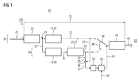
- FIG. 1 shows a control system that is designed to carry out a first embodiment of the inventive method 100 in a machine control 50.
- an input signal 20 is provided for a first machine axis 10 that enters the claimed method 100 at an input unit 22.
- a signal passage 35 takes place in the direction of an output unit 44, which outputs an output signal 40 to a drive means 52, not shown in greater detail.
- a duplication 24 of the input signal 20 takes place, so that a first and a second setpoint filter 26, 28 are fed with the identical input signal 20.
- the first setpoint filter 26 is arranged in a first filter strand 32 and the second setpoint filter 28 in a parallel second filter train 34.
- Both setpoint filters 26, 28 each have a different transit time 19.
- the first setpoint filter 26 generates from the input signal 20, a first output signal 23.
- the second setpoint filter 28 generates from the input signal 20, a second output signal 33, which is forwarded to a delay element 31.
- the delay element 31 has an adjustable dead time 25 and is neutral with respect to the second output signal 33.
- the second output signal 33 is forwarded via a signal branch 29 to a subtraction unit 36.
- the first output signal 23 from the first setpoint filter 26 is also forwarded via a signal branch 29 to the subtraction unit.
- the subtraction unit 36 forms the difference 37 between the first and second output signals 23, 33 and forwards the difference 37 to a comparator 38.
- the comparator 38 is designed to detect whether the difference 37 falls below an adjustable threshold.
- a presence of a difference 37 which is lower than the adjustable threshold value is forwarded to an instruction unit 39.
- the command unit 39 is designed to receive a switching command 42 from a higher-level controller and outputs a switching command 43 if a difference 37 of the output signals 23, 33 below the threshold value is simultaneously reported by the comparator 38.
- a switching operation 48 of a switching means 46 is caused.
- the switching means 46 determines by its switching state, which of the two setpoint filters 26, 28 is connected to the output unit 44.
- FIG. 1 corresponds to the sum of the term 19 and the dead time 25 of the second setpoint filter 28 and the delay element 31 is substantially the term 19 of the first setpoint filter 26.
- the subtraction unit 36 always corresponding, ie synchronous output signals 23, 33 at.
- states in which a switching process 48 can be carried out smoothly are detected with minimized delay. This allows you to switch the setpoint filter 26, 28 states are used, which are suitable only for a short time for smooth filter switching.
- FIG. 2 shows a control system that is designed to carry out a second embodiment of the inventive method 100 in a machine control 50.
- an input signal 20 is provided for a first machine axis 10 that enters the claimed method 100 at an input unit 22.
- a signal passage 35 takes place in the direction of an output unit 44, which outputs an output signal 40 to a drive means 52, not shown in greater detail.
- a duplication 24 of the input signal 20 takes place, so that a first and a second setpoint filter 26, 28 are fed with the identical input signal 20.
- the first setpoint filter 26 is arranged in a first filter strand 32 and the second setpoint filter 28 in a parallel second filter strand 34.
- Both setpoint filters 26, 28 each have a different duration 19.
- the first setpoint filter 26 generates from the input signal 20, a first output signal 23, which is forwarded to a first delay element 30.
- the second setpoint filter 28 generates from the input signal 20 a second output signal 33, which is forwarded to a second delay element 31.
- the delay elements 30, 31 each have an adjustable dead time 25 and behave in each case to the first and second output signals 23, 33 neutral.
- the second output signal 33 is forwarded, along the signal run 35, behind the second delay element 31 via a signal branch 29 to a subtraction unit 36.
- the first output signal 23 is also forwarded to the subtraction unit 36 after the first delay element 30 via a signal branch 29.
- the subtraction unit 36 forms the difference 37 between the first and second output signals 23, 33 and forwards the difference 37 to a comparator 38.
- the comparator 38 is designed to detect whether the difference 37 falls below an adjustable threshold. A presence of a difference 37, which is lower than the adjustable threshold value, is forwarded to a command unit 39.
- the command unit 39 is designed to receive a switching command 42 from a higher-level controller and outputs a switching command 43 if a difference 37 of the output signals 23, 33 below the threshold value is simultaneously reported by the comparator 38. By the switching command 43, a switching operation 48 of a switching means 46 is caused.
- the switching means 46 determines by its switching state, which of the two setpoint filters 26, 28 is connected to the output unit 44.
- FIG. 3 schematically a third embodiment of the inventive method 100 is shown, in each of which a switching operation 48 of setpoint filters 26, 28 for a first machine axis 10 and a second machine axis 12 is performed.
- An input signal 20, which enters the claimed method 100 at an input unit 22, is provided on each of the first and second machine axes 10, 12. Based on the two machine trains 10, 12, the input signals 20 are independent of each other.
- a signal passage 35 takes place in the direction of an output unit 44, which outputs an output signal 40 to a drive means 52, not shown in greater detail.
- a duplication 24 of the input signal 20 takes place, so that a first and a second setpoint filter 26, 28 are fed with the identical input signal 20.
- the first setpoint filter 26 is arranged in a first filter strand 32 and the second setpoint filter 28 in a parallel second filter strand 34. Both setpoint filters 26, 28 each have a different duration 19.
- the first setpoint filter 26 generates from the input signal 20, a first output signal 23, which is forwarded to a first delay element 30.
- the second setpoint filter 28 generates from the input signal 20 a second output signal 33, which is forwarded to a second delay element 31.
- the delay elements 30, 31 each have an adjustable dead time 25 and behave in each case to the first and second output signals 23, 33 neutral.
- the second output signal 33 is forwarded, along the signal run 35, behind the second delay element 31 via a signal branch 29 to a subtraction unit 36.
- the first output signal 23 is also forwarded to the subtraction unit 36 after the first delay element 30 via a signal branch 29.
- the subtraction unit 36 forms the difference 37 between the first and second output signals 23, 33 and forwards the difference 37 to a comparator 38.
- the comparator 38 is designed to detect whether the difference 37 falls below an adjustable threshold. A presence of a difference 37 which is lower than the adjustable threshold value is forwarded to an instruction unit 39.
- the command units 39 are each designed to receive a switching command 42 from a higher-level control and in each case output a switching command 43 if differences 37 of the output signals 23, 33 below the respective threshold values are reported at the same time for each machine axis 10, 12 by the associated comparator 38 , By the switching commands 43 separate switching operations 48 are caused by switching means 46.
- Each switching means 46 determines by its switching state, which of the two setpoint filters 26, 28 is connected to the corresponding output unit 44.
- the dead times 25 in the delay elements 30, 31 of the first and second machine axes 10, 12 are selected such that the respective combined transit times 19 and dead times 25 of the filter strands 32, 34 in both machine axes 10, 12 are substantially equal.
- the subtraction units 36 in the first and second machine axis 10, 12 despite independent input signals 20 always mutually corresponding, ie substantially synchronous output signals 23, 33.
- a smooth filter switching is achieved for both machine axes 10, 12 simultaneously.
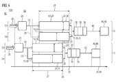
- FIG. 4 shows a flowchart of a fourth embodiment of the inventive method 100.
- the diagram shows a time axis 90, along which the signal passage 35 takes place.
- the broken vertical lines form on the time axis 90 simultaneously occurring events.
- a control input 42 of a higher-level control not shown, after which a filter switching for two machine axes 10, 12 is performed.
- the input signals 20 include position setpoints, speed setpoints and acceleration setpoints that are stored in FIG. 4 are indicated by a plurality of arrows.
- each setpoint filter 26, 28 different maturities 19 before.
- the duration of a running time 19 is represented by the dimensions of the target value filters 26, 28 associated areas.
- Each of the setpoint filters 26, 28 in the machine axes 10, 12 is associated with a delay element 30, 31, which in turn each has its own adjustable dead time 25.
- the signal passage 35 of the output signals 23, 33 is delayed in each filter train 32, 34 by the sum of the transit time 19 and the dead time 25 of the associated desired value filter 26, 28 and its delay element 30, 31.
- the adjustable dead times 25 of Delay elements 30, 31 are selected such that a substantially equal total transit time 27 results for the filter strands 32, 34 of each machine axis 10, 12.
- the output signals 31, 33 are in the machine axes 10, 12 at different output times 45 their associated subtraction units 36, and thus also the respective comparators 38 and command units 39, forwarded.
- a state suitable for a switching operation 48 is in FIG. 4 for each individual machine axis 10, 12, so that a separate switching command 43 for actuating the switching means 46 is given for both machine axes 10, 12.
- the conversion of the Umschaltbehle 43 takes place at a different time.
- FIG. 5 shows a flow chart of a fifth embodiment of the method 100 according to the invention.
- the diagram shows a time axis 90 along which the signal passage 35 takes place. The broken vertical lines form on the time axis 90 simultaneously occurring events.
- FIG. 4 is a control input 42 of a higher-level control, not shown, after which a filter switching for two machine axes 10, 12 is performed.
- the input signals 20 include position setpoints, speed setpoints and acceleration setpoints that are stored in FIG.
- Each of the setpoint filters 26, 28 in the machine axes 10, 12 is associated with a delay element 30, 31, which in turn each has its own adjustable dead time 25.
- the signal passage 35 of the output signals 23, 33 is delayed in each filter train 32, 34 by the sum of the time 19 and the dead time 25 of the associated setpoint filter 26, 28 and its delay element 30, 31.
- the adjustable dead times 25 of the delay elements 30, 31 are initially selected in both machine axes 10, 12 such that for the filter strands 32, 34 in each case one machine axis 10, 12 results in a substantially equal total transit time 27.
- the duration of the dead times 25 of the first and second delay elements 30, 31 is subsequently increased by an adaptation 47.
- the supplement 47 of the dead times 25 is designed such that the output signals 23, 33 of the first and second machine axes 10, 12 are forwarded to the respective subtraction units 36 at the same output time 45.
- the output signals 31, 33 are in the machine axes 10, 12 at different output times 45 their associated subtraction units 36, and thus also the respective comparators 38 and command units 39, forwarded.
- a suitable state for the switching operations 48 is in FIG. 4 for each individual machine axis 10, 12, so that a separate switching command 43 for actuating the switching means 46 is given for both machine axes 10, 12.
- the conversion of the switching commands 43, and thus the implementation of the switching operations 48, takes place at the same time.
Landscapes
- Engineering & Computer Science (AREA)
- Physics & Mathematics (AREA)
- Computer Hardware Design (AREA)
- Mathematical Physics (AREA)
- Human Computer Interaction (AREA)
- Manufacturing & Machinery (AREA)
- General Physics & Mathematics (AREA)
- Automation & Control Theory (AREA)
- Numerical Control (AREA)
- Feedback Control In General (AREA)
- Control Of Electric Motors In General (AREA)
Priority Applications (6)
| Application Number | Priority Date | Filing Date | Title |
|---|---|---|---|
| EP15180564.5A EP3131202A1 (fr) | 2015-08-11 | 2015-08-11 | Procede d'inversion de filtre pour une commande de machine |
| PCT/EP2016/068944 WO2017025531A1 (fr) | 2015-08-11 | 2016-08-09 | Procédé de commutation de filtres pour une commande de machine |
| CN201680046968.5A CN107925400B (zh) | 2015-08-11 | 2016-08-09 | 机器控制系统的滤波器切换方法 |
| JP2018506829A JP6632710B2 (ja) | 2015-08-11 | 2016-08-09 | 機械制御部のためのフィルタ切り換え方法、プログラム、機械の制御ユニットおよび機械 |
| EP16751567.5A EP3314761B1 (fr) | 2015-08-11 | 2016-08-09 | Procede de commutation de filtre pour une commande de machine |
| US15/751,774 US10491195B2 (en) | 2015-08-11 | 2016-08-09 | Filter switching method for a machine control system |
Applications Claiming Priority (1)
| Application Number | Priority Date | Filing Date | Title |
|---|---|---|---|
| EP15180564.5A EP3131202A1 (fr) | 2015-08-11 | 2015-08-11 | Procede d'inversion de filtre pour une commande de machine |
Publications (1)
| Publication Number | Publication Date |
|---|---|
| EP3131202A1 true EP3131202A1 (fr) | 2017-02-15 |
Family
ID=53800888
Family Applications (2)
| Application Number | Title | Priority Date | Filing Date |
|---|---|---|---|
| EP15180564.5A Withdrawn EP3131202A1 (fr) | 2015-08-11 | 2015-08-11 | Procede d'inversion de filtre pour une commande de machine |
| EP16751567.5A Active EP3314761B1 (fr) | 2015-08-11 | 2016-08-09 | Procede de commutation de filtre pour une commande de machine |
Family Applications After (1)
| Application Number | Title | Priority Date | Filing Date |
|---|---|---|---|
| EP16751567.5A Active EP3314761B1 (fr) | 2015-08-11 | 2016-08-09 | Procede de commutation de filtre pour une commande de machine |
Country Status (5)
| Country | Link |
|---|---|
| US (1) | US10491195B2 (fr) |
| EP (2) | EP3131202A1 (fr) |
| JP (1) | JP6632710B2 (fr) |
| CN (1) | CN107925400B (fr) |
| WO (1) | WO2017025531A1 (fr) |
Families Citing this family (3)
| Publication number | Priority date | Publication date | Assignee | Title |
|---|---|---|---|---|
| EP3561621B1 (fr) | 2018-04-26 | 2023-01-04 | Siemens Aktiengesellschaft | Détermination d'une valeur directrice ajustée |
| EP3616862A1 (fr) * | 2018-08-27 | 2020-03-04 | Siemens Aktiengesellschaft | Guidage d'une tête de coupe relativement à un produit à couper |
| JP7459776B2 (ja) * | 2020-12-02 | 2024-04-02 | 株式会社島津製作所 | 材料試験機、及び材料試験機の制御方法 |
Citations (3)
| Publication number | Priority date | Publication date | Assignee | Title |
|---|---|---|---|---|
| EP0135024B1 (fr) | 1983-09-15 | 1989-09-27 | ANT Nachrichtentechnik GmbH | Dispositif de transfert pour signaux numériques |
| EP0477412A1 (fr) | 1990-09-27 | 1992-04-01 | Siemens Aktiengesellschaft | Procédé pour filtrage de signaux digitaux |
| EP2418773A1 (fr) * | 2010-07-28 | 2012-02-15 | Brandenburgische Technische Universität Cottbus | Filtre FIR commutable sans impulsions transitoires |
Family Cites Families (26)
| Publication number | Priority date | Publication date | Assignee | Title |
|---|---|---|---|---|
| DE3408551A1 (de) * | 1984-03-08 | 1985-09-12 | Siemens AG, 1000 Berlin und 8000 München | Verfahren zum verringern von bahnfehlern bei rechnergesteuerten werkzeugmaschinen oder industrierobotern |
| US7236913B2 (en) | 2001-01-18 | 2007-06-26 | Siemens Aktiengesellschaft | Method for simulating a mechatronic system |
| DE10246093C1 (de) * | 2002-10-02 | 2003-11-27 | Siemens Ag | Verfahren zur Dämpfung mechanischer Schwingungen von Achsen von Werkzeugmaschinen, Produktionsmaschinen oder Robotern |
| JP2004227163A (ja) * | 2003-01-21 | 2004-08-12 | Fanuc Ltd | サーボ制御装置 |
| DE10321970A1 (de) | 2003-05-15 | 2004-12-09 | Siemens Ag | Verfahren zur Bewegungsführung eines bewegbaren Maschinenelementes einer numerisch gesteuerten Werkzeug-oder Produktionsmaschine |
| SE0301531L (sv) * | 2003-05-22 | 2004-11-23 | Abb Ab | A Control method for a robot |
| JP2005044330A (ja) * | 2003-07-24 | 2005-02-17 | Univ Of California San Diego | 弱仮説生成装置及び方法、学習装置及び方法、検出装置及び方法、表情学習装置及び方法、表情認識装置及び方法、並びにロボット装置 |
| US7107119B2 (en) | 2003-10-27 | 2006-09-12 | Siemens Aktiengesellschaft | Controller for a machine tool or production machine |
| DE10355614B4 (de) * | 2003-11-28 | 2006-11-23 | Siemens Ag | Einrichtung und Verfahren zur Bewegungsaufteilung einer Bewegung eines Maschinenteils entlang einer Antriebsachse einer Werkzeug- oder Produktionsmaschine |
| JP4276187B2 (ja) * | 2005-02-02 | 2009-06-10 | ファナック株式会社 | 学習制御機能を有する数値制御装置 |
| JP4361071B2 (ja) * | 2005-07-08 | 2009-11-11 | ファナック株式会社 | サーボ制御装置 |
| DE102005048390A1 (de) | 2005-10-10 | 2007-04-19 | Siemens Ag | Verfahren und Einrichtung zur Bewegungsführung eines bewegbaren Maschinenelementes einer Maschine |
| JP2008225533A (ja) * | 2007-03-08 | 2008-09-25 | Fanuc Ltd | サーボ制御装置 |
| EP2174748B1 (fr) | 2008-10-10 | 2011-06-29 | Siemens Aktiengesellschaft | Machine-outil et procédé d'amortissement d'oscillations d'un élément de machine d'une machine-outil |
| JP4575508B1 (ja) * | 2009-05-20 | 2010-11-04 | ファナック株式会社 | デュアル位置フィードバック制御を行うサーボ制御装置 |
| CN201523362U (zh) * | 2009-11-10 | 2010-07-07 | 希姆通信息技术(上海)有限公司 | 滤波设备 |
| JP4728422B2 (ja) * | 2009-12-09 | 2011-07-20 | ファナック株式会社 | 高速揺動動作を高精度化するサーボ制御システム |
| WO2012057235A1 (fr) * | 2010-10-27 | 2012-05-03 | 株式会社牧野フライス製作所 | Procédé de commande numérique |
| EP2605095A1 (fr) | 2011-12-14 | 2013-06-19 | Siemens Aktiengesellschaft | Machine de traitement dotée d'un contrôle d'accès par réseau informatique |
| JP5374613B2 (ja) * | 2012-05-30 | 2013-12-25 | 株式会社神戸製鋼所 | 多関節ロボットの弾性変形補償制御装置および制御方法 |
| EP2954986B1 (fr) | 2014-06-10 | 2020-05-06 | Siemens Aktiengesellschaft | Dispositif et procédé de commande et de réglage d'un système multi-corps |
| JP5897662B2 (ja) * | 2014-07-30 | 2016-03-30 | ファナック株式会社 | 複数軸の加工精度を向上させるサーボモータの制御装置 |
| EP2988181B1 (fr) | 2014-08-19 | 2019-07-03 | Siemens Aktiengesellschaft | Dispositif de réglage à compensation d'erreur adaptative |
| US20160090288A1 (en) * | 2014-09-29 | 2016-03-31 | Monsieur Llc | Automated Mixed Drink Dispenser |
| JP6392805B2 (ja) * | 2016-04-12 | 2018-09-19 | ファナック株式会社 | 複数モータ駆動用サーボ制御装置 |
| JP6404863B2 (ja) * | 2016-06-27 | 2018-10-17 | ファナック株式会社 | 加減速フィルタの時定数を動的に切り替える数値制御装置 |
-
2015
- 2015-08-11 EP EP15180564.5A patent/EP3131202A1/fr not_active Withdrawn
-
2016
- 2016-08-09 WO PCT/EP2016/068944 patent/WO2017025531A1/fr not_active Ceased
- 2016-08-09 US US15/751,774 patent/US10491195B2/en active Active
- 2016-08-09 EP EP16751567.5A patent/EP3314761B1/fr active Active
- 2016-08-09 CN CN201680046968.5A patent/CN107925400B/zh active Active
- 2016-08-09 JP JP2018506829A patent/JP6632710B2/ja active Active
Patent Citations (3)
| Publication number | Priority date | Publication date | Assignee | Title |
|---|---|---|---|---|
| EP0135024B1 (fr) | 1983-09-15 | 1989-09-27 | ANT Nachrichtentechnik GmbH | Dispositif de transfert pour signaux numériques |
| EP0477412A1 (fr) | 1990-09-27 | 1992-04-01 | Siemens Aktiengesellschaft | Procédé pour filtrage de signaux digitaux |
| EP2418773A1 (fr) * | 2010-07-28 | 2012-02-15 | Brandenburgische Technische Universität Cottbus | Filtre FIR commutable sans impulsions transitoires |
Also Published As
| Publication number | Publication date |
|---|---|
| EP3314761A1 (fr) | 2018-05-02 |
| WO2017025531A1 (fr) | 2017-02-16 |
| JP6632710B2 (ja) | 2020-01-22 |
| CN107925400A (zh) | 2018-04-17 |
| US20180241376A1 (en) | 2018-08-23 |
| EP3314761B1 (fr) | 2022-06-22 |
| CN107925400B (zh) | 2021-10-15 |
| JP2018530813A (ja) | 2018-10-18 |
| US10491195B2 (en) | 2019-11-26 |
Similar Documents
| Publication | Publication Date | Title |
|---|---|---|
| DE102007006422B4 (de) | Verfahren zum Betreiben von Maschinen mit anpassbaren Bewegungsprofilen | |
| DE112013007679B4 (de) | Numerische Steuerungsanlage und numerisches Steuerungsverfahren | |
| EP0787319B1 (fr) | Commande de vitesse a limitation de couple | |
| EP1956452B1 (fr) | Procédé destiné au fonctionnement de machines commandées | |
| EP3321754B1 (fr) | Procédé d'optimisation de profiles de mouvement, produit-programme informatique, dispositif de commande et installation ou robot | |
| DE102016012634B4 (de) | Numerische Steuerung mit krümmungs- und krümmungsänderungsabhängiger Geschwindigkeitssteuerung | |
| EP3314761B1 (fr) | Procede de commutation de filtre pour une commande de machine | |
| WO2019166229A1 (fr) | Procédé pour la génération automatique d'une trajectoire de déplacement et produit de programme informatique associé | |
| DE102017007912A1 (de) | Laser-Controller | |
| DE102016012042B4 (de) | Numerische Steuerung mit Positionierung zur Vermeidung einer Kollision mit einem Werkstück | |
| WO2011110289A1 (fr) | Procédé de détermination d'un tracé de courbe nominale optimisé dans une machine à plusieurs axes pour le traitement volant de produit transporté | |
| EP1428087B1 (fr) | Procede de commande de trajectoire | |
| EP0988584B1 (fr) | Procede et dispositif pour la commande d'une avance de contournage | |
| WO2023174637A1 (fr) | Meulage dépendant de la vitesse entre des ensembles ayant des trajectoires discontinues | |
| DE3943342C2 (de) | Servosteuersystem | |
| EP2460597A1 (fr) | Procédé de commande d'une voie de laminage en tandem, dispositif de commande et/ou de réglage pour une voie de laminage en tandem, code de programme lisible par machine, support de stockage et voie de laminage en tandem | |
| DE112017006003T5 (de) | Laserbearbeitungsmaschine und Laserbearbeitungssystem | |
| EP3627257B1 (fr) | Planification de mouvement pour un système de transport d'une installation de servopresse | |
| EP3887911A1 (fr) | Procédé de commande d'un processus d'automatisation en temps réel | |
| DE10260838A1 (de) | Verfahren und Vorrichtung zur Steuerung einer Kupplung innerhalb eines Kraftfahrzeugtriebstrangs | |
| DE102021211819B3 (de) | Verfahren zur Generierung eines Geschwindigkeitsprofils für eine Bahnsteuerung | |
| WO2002091092A2 (fr) | Procede servant a gerer un processus de transformation de l'acier, en particulier d'un processus de laminage a chaud | |
| EP3293590A1 (fr) | Évaluation automatique de la qualité d'une séquence d'ordres de déplacement | |
| DE102022110546A1 (de) | Steuereinheit und Steuerungsverfahren | |
| DD289832A5 (de) | Schaltungsanordnung zur folgesteuerung an bahnabschnittsuebergaengen |
Legal Events
| Date | Code | Title | Description |
|---|---|---|---|
| PUAI | Public reference made under article 153(3) epc to a published international application that has entered the european phase |
Free format text: ORIGINAL CODE: 0009012 |
|
| AK | Designated contracting states |
Kind code of ref document: A1 Designated state(s): AL AT BE BG CH CY CZ DE DK EE ES FI FR GB GR HR HU IE IS IT LI LT LU LV MC MK MT NL NO PL PT RO RS SE SI SK SM TR |
|
| AX | Request for extension of the european patent |
Extension state: BA ME |
|
| RAP1 | Party data changed (applicant data changed or rights of an application transferred) |
Owner name: SIEMENS AKTIENGESELLSCHAFT |
|
| STAA | Information on the status of an ep patent application or granted ep patent |
Free format text: STATUS: THE APPLICATION IS DEEMED TO BE WITHDRAWN |
|
| 18D | Application deemed to be withdrawn |
Effective date: 20170817 |