EP3131252A1 - Procédé et système de détection d'intrusion dans un réseau - Google Patents
Procédé et système de détection d'intrusion dans un réseau Download PDFInfo
- Publication number
- EP3131252A1 EP3131252A1 EP15180738.5A EP15180738A EP3131252A1 EP 3131252 A1 EP3131252 A1 EP 3131252A1 EP 15180738 A EP15180738 A EP 15180738A EP 3131252 A1 EP3131252 A1 EP 3131252A1
- Authority
- EP
- European Patent Office
- Prior art keywords
- node
- network
- data
- field
- data item
- Prior art date
- Legal status (The legal status is an assumption and is not a legal conclusion. Google has not performed a legal analysis and makes no representation as to the accuracy of the status listed.)
- Granted
Links
Images


Classifications
-
- H—ELECTRICITY
- H04—ELECTRIC COMMUNICATION TECHNIQUE
- H04L—TRANSMISSION OF DIGITAL INFORMATION, e.g. TELEGRAPHIC COMMUNICATION
- H04L63/00—Network architectures or network communication protocols for network security
- H04L63/14—Network architectures or network communication protocols for network security for detecting or protecting against malicious traffic
- H04L63/1408—Network architectures or network communication protocols for network security for detecting or protecting against malicious traffic by monitoring network traffic
- H04L63/1425—Traffic logging, e.g. anomaly detection
-
- H—ELECTRICITY
- H04—ELECTRIC COMMUNICATION TECHNIQUE
- H04L—TRANSMISSION OF DIGITAL INFORMATION, e.g. TELEGRAPHIC COMMUNICATION
- H04L63/00—Network architectures or network communication protocols for network security
- H04L63/14—Network architectures or network communication protocols for network security for detecting or protecting against malicious traffic
- H04L63/1408—Network architectures or network communication protocols for network security for detecting or protecting against malicious traffic by monitoring network traffic
-
- H—ELECTRICITY
- H04—ELECTRIC COMMUNICATION TECHNIQUE
- H04L—TRANSMISSION OF DIGITAL INFORMATION, e.g. TELEGRAPHIC COMMUNICATION
- H04L69/00—Network arrangements, protocols or services independent of the application payload and not provided for in the other groups of this subclass
- H04L69/22—Parsing or analysis of headers
Definitions
- the present invention relates to a method and a system for the detection of an intrusion in a computer network.
- malicious applications are generally unintentionally executed by the operating system of an infected host and thus run as a process or thread on said operating system.
- Current strategies to detect and eliminate such malicious application include the use of scanners that search the storage media of the host for known signatures of the malicious application.
- one object of the present invention is the provision of a method and a system for the detection of the intrusion in a computer network that is not dependent on the adaptation and provision of signatures. It is a further object of the present invention to provide a method and a system to detect such intrusions in real time. An even further object of the present invention is the provision of a method and a system to detect an intrusion in a computer network, wherein the malicious software is not executed by the operating system of an intruded host and/or bypasses the operating system of said host.
- the present invention provides a method for identifying an intrusion in a computer network, wherein the method comprises the steps of collecting at least one first data set comprising at least one host data item derived from the network traffic that originates from an operating system and/or is controlled by an operating system installed on at least one first node of the computer network; collecting a second data set comprising at least one node data item derived from the network traffic originating from the at least one first node; and comparing whether the second data set comprises at least one data item that differs from a corresponding data item within the at least one first data set. If such a difference is determined an intrusion in the computer network is assumed and/or detected.
- One underlying concept of the present invention is the comparison of the network traffic monitored at two different points in the network.
- the network traffic generated by - and thus known to - the operating system of one node of a network is compared with the network traffic that is factually sent into the network by this node.
- the network traffic generated by the operating system of a node is monitored by means executed on and/or controlled by said operating system (such as an application) while the network traffic that is factually sent into the network by this node is monitored by means not executed on and/or controlled by said operating system of the monitored node (such as a network sniffer, a router, switch, and/or gateway in the network).
- said operating system of the monitored node such as a network sniffer, a router, switch, and/or gateway in the network.
- the latter means are more preferably not executed by and/or located on the monitored host.
- a plurality of such nodes of a computer network can be monitored in this manner to detect an intrusion of these nodes and/or the computer network they are part of.
- the network traffic monitored at these two different points in the network should be identical. If, however, differences are detected this may indicate an intrusion of the computer network, in particular the intrusion of the monitored node by malware bypassing the node's operating system.
- the method according to the invention preferably is a computer implemented method. It monitors the network traffic in a computer network at at least two distinct points to detect malicious activities and/or software.
- the computer network can be any type of network known to the skilled person which comprises at least two nodes that can exchange data. Said nodes of the computer network are connected by network links which can, for example, be established by cable media or wireless media. Examples for a computer network are the internet, or an intranet. Preferably, the computer network of the present invention is an intranet connected to, preferably by means of a gateway, the internet.
- each data set preferably consist of at least one data item that is derived from the network traffic.
- derived data items preferably comprise a source network address, a destination network address, a source port, a destination port, or information regarding the length of the data transmitted in the network.
- the network protocol is an internet protocol (IP) - such as the Ethernet protocol - and the transmitted network data comprises header fields that store the before mentioned information.
- IP internet protocol
- a data set comprises more than one data item, more preferably it comprises one or more header fields of the Ethernet network frames. Even more preferably, these header fields are grouped within the data set, preferably they are grouped by source network address, destination network address, source port, destination port, and/or an information regarding the length of the transmitted data. More preferably, they are grouped by source network address and/or destination network address.
- one key idea of the present invention is the monitoring or collection of network traffic data at at least two different points in the network in order to compare such data sets for inconsistencies.
- At least one first set of data is collected and/or derived from the network traffic that originates from an operating system (OS) and/or is controlled by an operating system installed on at least one first node of the computer network.
- the network comprises more than one first node that is monitored and more than one first data set is consequently collected.
- the first set of data comprises data items that are generated and/or controlled by the OS executed on the first node that is monitored.
- these data items do not comprise data items generated by malicious software, i.e. software not part of the OS but executed, installed and/or run by or on the OS.
- the network traffic generated by the malicious software is usually unknown to the OS. In the following, such data items are designated "host data items".
- the second set of data is collected and/or derived from the network traffic actually originating from the monitored first node.
- the second set of data comprises data items which are factually and/or physically sent into the computer network by the at least one first node monitored.
- the second data set comprises the data items derived from the network traffic that originates from an operating system (OS) and/or is controlled by an operating system installed on said first node of the computer network (i.e. the data items also comprised by the first data set) and additionally may comprise data items that are derived from network traffic that is generated by the first node but does not originate from an operating system (OS) and/or is not controlled by an operating system installed on said first node of the computer network (data traffic generated by malicious software).
- OS operating system
- OS operating system
- the second set of data may preferably comprise and/or be derived from the total network traffic generated by more than one first node monitored.
- the second set of data comprises data items derived from the network traffic physically sent into the computer network by all of these first nodes. In the following, such data items are designated "node data items”.
- the data items of first and second data set are compared for inconsistencies. More particular, it is compared whether the second data set comprises at least one data item that differs from a corresponding data item within the at least one first data set.
- comparing in said method step it is preferably meant to determine whether for a given node data item a corresponding, preferably an identical, host data item is present in the two data sets.
- differs in said method step missing, altered or additional data items, preferably altered and/or additional data items, most preferably additional data items may be designated.
- a preferred example of such differing data items in the two compared data sets are destination network address and/or destination port data present as data item in the second data set but lacking from the first data set.
- a further preferred example of such differing data items may be a data item in the second data set storing the length/amount of the transmitted data wherein the corresponding data item in the first data set stores an altered, i.e. different, length/amount of data transmitted.
- corresponding in particular regarding the comparison step of the inventive method, may designate that a given data item in the compared (first) data set of host data items is expected to have a certain value based on a given data item in the (second) data set of node data items. For example, if the second data set comprises a node data item referring to a specific destination network address (such as an IP address) an identical host data item is expected to be present in the first data set. If such is not the case this might be an indication for an intrusion of the network.
- a specific destination network address such as an IP address
- the data items are grouped in the data sets. Therefore, another preferred example is the comparison of a node data item referring to the length and/or amount of data sent grouped together with the data items of source network address and/or destination network address with a corresponding host data item in the same group of data items.
- groups of data items in the second data set may be compared to corresponding groups of data items in first data set.
- the comparison may be carried out for single data items, a plurality of data items, or all data items comprised in the data sets.
- the collected data items preferably comprise the source network address of the first node, such as its IP address in the network, said node can easily be identified. Consequently, the identified node may preferably be subjected to suitable counter measures, such as removal from the network, shutdown of the intruded node, and/or forensics to identify the malicious application.
- the host data item or host data items (and thus at least part of the first data set) is/are preferably collected by the at least one first node of the computer network. Even more preferably, the host data item(s) is/are collected by a first module installed and/or executed on the first node. Most preferably, the host data item(s) is/are collected by a first module installed and/or executed on the operating system of the first node.
- the first module can thus be described as a piece of software, i.e. a client or agent, run/executed on the first node of the network.
- the complete first data set comprising more than one host data items, may be collected by the at least one first node.
- the first module is installed on more than a single first node, most preferably it is installed on all first nodes of the network. It may be installed on all nodes of the network. This has the advantage that all first nodes of the network are monitored and an intrusion can more reliably be detected.
- the node data item or node data items (and thus at least part of the second data set) is/are preferably collected by at least one second node of the computer network, i.e. a further node of the network which is different from the first node collecting the host data item(s) of the first data set and/or which is not dependent on the OS of the first node.
- the node data item(s) is/are collected by a second module installed and/or executed on said second node.
- the node data item(s) is/are collected by a second module installed and/or executed on the operating system of the second node.
- the second module can thus be described as a piece of software or hardware run/executed/installed on the second node of the network or representing the second node of the network.
- the node data item or node data items may also be collected by the first node, provided that the means for the collection of these node data items are not dependent on the OS system of the first node.
- the node data item(s) may be collected by a second module built into the first node that is connected to the network and/or the network interface of said first node but not controlled by the OS of the first node.
- the second module is generally a separate piece of hardware built into the first node, which may be a PC.
- Such a separate piece of hardware is preferably a hardware security module (HSM) known to the skilled person.
- HSM hardware security module
- the comparison step of node data item and host data item can be carried out on/by any node of the network. Preferably it is carried out by an at least third node of the computer network. More preferably, by a third module installed and/or executed on said third node. Most preferably, the comparison is carried out by a third module installed and/or executed on the operating system of the third node the network.
- Said third node preferably is a further node of the network which is different from the first node collecting the host data item(s) of the first data set and, more preferably, is also different from the second node of the network collecting the node data items.
- the complete second data set may be collected by more than a single node of the network.
- the node data items are collected at more than one position in the network and, preferably, joined as the second data set at a single database.
- a database is a relational database such as an SQL database and/or a big data platform such as a Vertica Analytic Database, etc. that stores the second data set.
- This database can advantageously act as the third module to efficiently carry out the comparison step.
- the second data set is collected by a single node and/or module it may be stored in such a database.
- Second and third modules Physically separating second and third modules, i.e. data collection and comparison are carried out on different nodes, does offer certain advantages.
- the third module also comprising a database storing the considerable amount of data derived from the total data traffic in the network only this node needs to be large-dimensioned, while the one or more first and second nodes collecting the actual data may be kept small.
- the at least first node, the at least second node and the at least third node of the computer network can be any suitable device known to the skilled person that is able to participate in a computer network.
- the first node, the second node and the third node are independently selected from the group consisting of a PC, a mobile device, a mobile phone, a terminal, a network sniffer, a network bridge, a network switch, a network hub, a bridge, a gateway and a router.
- the first node is a mobile device and/or a PC.
- the second node more preferably is selected from the group consisting of a network sniffer, a network bridge, a network switch, a router and/or a gateway. Most preferably, the second node is a network switch, a gateway or a router.
- the second node preferably is a device that offers port mirroring functionality. This advantageously offers the possibility to effortless collect the network traffic of the whole network and/or all first nodes at a single point.
- the third node more preferably is a PC or a mainframe system, more preferably comprising a database.
- Each of the nodes of the network can execute an operating system (OS).
- OS operating system
- firmware e.g. executed on a switch or gateway
- OS Various OS are known to the skilled person, non-limiting examples including Windows, MAC OS, Linux, Unix, Android or Apple iOS.
- the collected data items of each data set preferably consist of at least one data item that is derived from the network traffic and referring to a source network address, a destination network address, a source port, a destination port, and/or information regarding the length of the data transmitted in the network.
- the host data item may comprise at least one field of a network frame of the data traffic that originates and/or is controlled by an operating system installed on the first node.
- the node data item may comprise at least one field of a network frame of the data traffic that originates, preferably factually and/or physically, from said at least one first node.
- the first data set and the second data set comprise data items that refer to the same fields of a network frame of the data traffic.
- the network frame is an Ethernet frame.
- Ethernet frames comprise header fields and information fields, wherein the information field may comprise further header fields of higher OSI layers.
- the data item of first and second data sets comprises a header field. This advantageously reduces the amount of data that needs to be handled, stored and/or compared by the system.
- the data item of first and second data sets comprises a header field that is a header field of the network layer, the transport layer, and/or the session layer of the OSI layers.
- these header fields are header fields of the TCP and/or UDP header.
- Preferable fields of the network layer are selected from the group consisting of the IP frame (comprising IP header and IP information field), the IP header field, the source address field, the destination address field, the total length field, the protocol field and/or the information field of the IP frame.
- Preferable fields of the transport layer are selected from the group consisting of the TCP frame (comprising TCP header and TCP information field), the TCP header field, the sequence number field, the information field of the TCP frame (comprising UDP header and UDP information field), the UDP frame, the UDP header field, the length field, the information field of the UDP frame, the source port field, the destination port field and/or the checksum field.
- the item of first and second data sets i.e. the host data item and the node data item, comprises at least one field of an Ethernet frame selected from the group consisting of the source address field, the destination address field, the total length field, the protocol field, the source port field and/or the destination port field.
- said field is selected from the group consisting of the source address field, the destination address field, the total length field, the source port field and/or the destination port field.
- the first and second data set comprises the following fields of at least a single Ethernet frame: the source address field, the destination address field, the total length field, the source port field, protocol field and/or the destination port field.
- the first and second data set comprises the following fields of at least a single Ethernet frame: the source address field, the destination address field, the total length field, the source port field and/or the destination port field. This has the advantage that the amount of data that has to be managed is even more reduced.
- the first and second data set comprises the following fields of at least a single Ethernet frame: the source address field, the destination address field.
- the data items in first and second data set are preferably grouped for each monitored Ethernet frame.
- the host data items in the first data set and the node data items in the second data set are grouped by the network frame they are derived from. This way a comparison is possible more easily and more efficiently, especially if it is carried out by a (relational) database.
- the first and second data set only consists of destination address field information. This has the advantage that the amount of data that has to be managed is reduced to the minimum and still an intrusion may be detected.
- the collected fields of a single Ethernet frame are those fields required to establish/identify a datagram socket and/or a stream socket. More preferably, in case of a connection oriented transport protocol, such as TCP, the collected fields of a single Ethernet frame are those fields required to establish/identify a stream socket. In other words, the fields collected in case of a connection oriented protocol can be grouped by session. In case of a connectionless transport protocol, such as UDP, the collected fields of a single Ethernet frame are those fields required to establish/identify a datagram socket.
- the first and/or second set of data preferably comprises an additional data item (a data stamp) referencing the time of collection of each data item in the first and/or second data set. More preferably, if more than one data item, i.e. fields, per single network frame are collected in the respective data sets, said data items are grouped by use of this data stamp, i.e. by the time the network traffic occurred.
- a data stamp can, for example, be derived from the internal clocks of the network node(s) the first, second, and/or third module is executed on. More preferably, the internal clocks of said nodes are synchronized, preferably by means of an NTP-server present in the network.
- the time stamp is generated during the storage of the data item of a data set into a database.
- Current databases offer the possibility to automatically assign a time stamp upon entry of a data item.
- the time stamp provides for efficient means to compare the data items in the two data sets.
- the generation of the first and second dataset is preferably carried out by collecting a plurality of host data items and a plurality of node data items, respectively starting from a first time (tO) for a predetermined time interval (M).
- tO first time
- M predetermined time interval
- the predetermined time interval usually is in the range of ⁇ 1 min and ⁇ 20 min. Preferably, it is about 5 min as this time interval has proven as highly effective with current networks and database systems handling the generated data.
- the first set of data may preferably further comprise at least one host-sum data item calculated from the total amount of network traffic in the predetermined time interval that originates from and/or is controlled by the operating system installed on at least one first node.
- the second set of data may preferably comprise at least one node-sum data item calculated from the total amount of network traffic in the predetermined time interval that originates from said first node.
- the total amount of data is preferably derived from the total length fields of the monitored network frames.
- host-sum data item and node-sum data item are preferably compared as the two respective data items of the two data sets in the comparison step according to the invention. In other words, the client-sum data items and node-sum data items are used as the data items of first and second set of data in the comparison step.
- the comparison according to the present invention can be carried out more efficiently and very reliably. If, for example, node-sum and host-sum data items for a given node of the network differ, this is an indication for an intrusion of the network, particularly of the network node the node-sum and host-sum data items have been derived from.
- the generation of the first and second dataset from a first time (tO) for a predetermined time interval (M) can preferably be repeated. Consequently, also the calculation of node-sum and host-sum data items can preferably be repeated. More preferably, the repetition is carried out periodically. This way, a continuous intrusion detection of the network is provided.
- a predetermined second time interval is inserted during which no monitoring takes place.
- the second time interval can be chosen depending on the needs and according to the capacities of the components of the network. Preferably, it is chosen randomly, i.e. with differing length each time, within predetermined boundaries. In other words, a time interval of random duration is inserted between two cycles of repetition.
- a computer system is provided. Said computer system is suitable to carry out the method according to the invention.
- the computer system comprises a computer network of at least two nodes and is suitable to detect an intrusion therein.
- the computer system comprises at least a first node and at least a second node interconnected via a network link, thereby creating a computer network. It furthermore comprises at least a first module, at least a second module and at least a third module.
- the computer system is characterized by the further following features: the first module is installed on the first node and adapted to collect at least one first data set comprising at least one host data item derived from the network traffic that originates from an operating system and/or is controlled by an operating system installed on said first node; the second module is adapted to collect a second data set comprising at least one node data item derived from the network traffic originating from the at least one first node; and the third module is adapted to compare whether the second data set comprises at least one data item that differs from a corresponding data item within the at least one first data set.
- the computer system is adapted to transmit network data utilizing a network protocol, preferably an internet protocol, more preferably the Ethernet protocol.
- the first, second, and third module may be hardware or software modules.
- the first module is a software module executed by the OS of the first node.
- the third module is a database, more preferably it is a relational database.
- second and third modules are installed on a second node.
- the computer system may preferably comprise a third node, the second module may be installed on the second node and the third module may be installed on said third node.
- the computer system according to the present invention may comprise, as a further node, a device to synchronize the clocks of the nodes of the network.
- this device is an NTP-server.
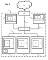
- Figure 1 gives a schematic view of a computer system (1) according to one embodiment of the invention.
- the computer system comprises an intranet (1) which is connected to the internet (15) by means of a gateway (14).
- the intranet (1) comprises several nodes, inter alia, three first nodes (2), a second node (7) and a third node (10).
- the first nodes (2), the second node (7), the third node (10) and the gateway (14) are connected to a network switch (13) by network links (6).
- the first nodes (2) comprise operating systems (3) installed and executed thereon. Likewise, operating systems are installed and executed on the second and third nodes (7,10).
- the operating systems of the first nodes (3) are Microsoft Windows operating systems.
- the operating systems of second and third nodes (8, 11) are Linux operating systems.
- first software module (5) is installed that is executed by the operating system of the first modules (3).
- These first modules (5) are adapted to monitor the network traffic that originates from the operating system (3) and/or is controlled by the operating system installed on at least one first node (2). Thereby, first data sets comprising at least one host data item are collected. These may be sent over the network to the third module (12).
- a second software module (9) is installed and executed on the second node (7) which is connected to the network via network switch (13) that offers a port mirroring functionality. Thereby, all network traffic originating from the first nodes (2) may conveniently be monitored.
- the second module (9) is adapted to monitor the network traffic that originates from at least one of the three first nodes (2). Thereby, a second data set comprising at least one node data item is collected. Said second data set may likewise be sent over the network to the third module (12).
- the network (1) has been intruded by a malicious software (4).
- Said malicious software (4) is executed on one of the first nodes (2) and generates additional network traffic.
- the malicious software (4) however, is not installed on the operating system (3) itself. Therefore, it bypasses the operating system (3) or - in other words - the operating system is not aware of the additional network traffic generated by the malicious software. Consequently, the first module (5) executed by the operating system (3) of the first node cannot monitor the additional network traffic generated by the malicious software (4).
- said additional network traffic generated by the malicious software (4) on the first node (2) will be monitored by the second module (9) installed on the second node (7). This is due to the fact that the second node (2) is monitoring the first node (2) from "the outside” and thereby is able to detect all factual/physical network traffic sent into the network (1) by the first node (2) intruded by the malicious software (4).
- the third module (12) installed and executed on the third node (10) is adapted to compare the node data item(s) in the second data set with (a) corresponding host data item(s) in the first data set. Particularly, it is adapted to determine whether a given node data item differs from a corresponding host data item. If such is the case, the third module (12) may raise an alarm to signal a potential intrusion of the network.
- the third module (12) is a relational database, such as an SQL database, which advantageously makes a storing and comparing of the two data sets very convenient and quick.
- the third module (12) may identify the specific first module (2) on which the malicious software (4) is executed. As an example, this information could be derived from the source address field of the TCP or UDP header of the deriving node data item.
- Figure 2 gives a schematic view of a computer system (1) according to a further embodiment of the invention.
- the network (1) comprises only three first nodes (2) and a second node (7).
- the operating system (8) of the second node which is a Linux operating system, both the second module (9) and the third module (12) are installed and executed.
- first and second data sets collected by the second module (9) need not be transferred over the network (1) to a third module hosted on a third node.
- the second (9) and/or third (12) module may likewise be installed and executed on the operating system of the gateway (14), or even the operating system (firmware) of the network switch (13).
- Figure 3 gives a schematic view of a computer system (1) according to an even further embodiment of the invention.
- the network setup corresponds to the network setup of figure 1 with the addition that the network (1) comprises an NTP-server (16).
- Said NTP-server is likewise connected to the network switch (13) and thus able to provide a timing signal to all further nodes in the network (1).
- first nodes (2) and second node (2) are thus able to synchronize their internal clocks.
- the data items collected in the first and second data set can then advantageously comprise a time stamp as a further data item. This way, it is possible to retrace the exact time when a given network traffic occurred. Consequently, the data sets can be compared more conveniently.
Landscapes
- Engineering & Computer Science (AREA)
- Computer Security & Cryptography (AREA)
- Computer Networks & Wireless Communication (AREA)
- Signal Processing (AREA)
- Computer Hardware Design (AREA)
- Computing Systems (AREA)
- General Engineering & Computer Science (AREA)
- Data Exchanges In Wide-Area Networks (AREA)
Priority Applications (3)
| Application Number | Priority Date | Filing Date | Title |
|---|---|---|---|
| EP15180738.5A EP3131252B1 (fr) | 2015-08-12 | 2015-08-12 | Procédé et système de détection d'intrusion dans un réseau |
| US15/752,047 US20180241763A1 (en) | 2015-08-12 | 2016-06-30 | Method and system for network intrusion detection |
| PCT/EP2016/065401 WO2017025243A1 (fr) | 2015-08-12 | 2016-06-30 | Procédé et système pour détecter une intrusion dans un réseau |
Applications Claiming Priority (1)
| Application Number | Priority Date | Filing Date | Title |
|---|---|---|---|
| EP15180738.5A EP3131252B1 (fr) | 2015-08-12 | 2015-08-12 | Procédé et système de détection d'intrusion dans un réseau |
Publications (2)
| Publication Number | Publication Date |
|---|---|
| EP3131252A1 true EP3131252A1 (fr) | 2017-02-15 |
| EP3131252B1 EP3131252B1 (fr) | 2018-09-26 |
Family
ID=53886904
Family Applications (1)
| Application Number | Title | Priority Date | Filing Date |
|---|---|---|---|
| EP15180738.5A Not-in-force EP3131252B1 (fr) | 2015-08-12 | 2015-08-12 | Procédé et système de détection d'intrusion dans un réseau |
Country Status (3)
| Country | Link |
|---|---|
| US (1) | US20180241763A1 (fr) |
| EP (1) | EP3131252B1 (fr) |
| WO (1) | WO2017025243A1 (fr) |
Families Citing this family (1)
| Publication number | Priority date | Publication date | Assignee | Title |
|---|---|---|---|---|
| US10491613B1 (en) | 2019-01-22 | 2019-11-26 | Capital One Services, Llc | Systems and methods for secure communication in cloud computing environments |
Citations (3)
| Publication number | Priority date | Publication date | Assignee | Title |
|---|---|---|---|---|
| KR20030063949A (ko) * | 2002-01-24 | 2003-07-31 | 박정현 | 컴퓨터 바이러스 방역 방법 및 시스템 |
| US20050108377A1 (en) * | 2003-11-18 | 2005-05-19 | Lee Soo-Hyung | Method for detecting abnormal traffic at network level using statistical analysis |
| KR20080040257A (ko) * | 2006-11-02 | 2008-05-08 | 한국전자통신연구원 | 네트워크 수준의 웜, 바이러스 조기 탐지 방법 및 장치 |
Family Cites Families (6)
| Publication number | Priority date | Publication date | Assignee | Title |
|---|---|---|---|---|
| JP3613102B2 (ja) * | 1999-12-14 | 2005-01-26 | 日本電気株式会社 | フレーム構成方法、フレーム構成装置およびフレーム構成転送システム |
| US7228564B2 (en) * | 2003-07-24 | 2007-06-05 | Hewlett-Packard Development Company, L.P. | Method for configuring a network intrusion detection system |
| US7804787B2 (en) * | 2005-07-08 | 2010-09-28 | Fluke Corporation | Methods and apparatus for analyzing and management of application traffic on networks |
| US20120174220A1 (en) * | 2010-12-31 | 2012-07-05 | Verisign, Inc. | Detecting and mitigating denial of service attacks |
| US20130275905A1 (en) * | 2012-04-11 | 2013-10-17 | Secondprism Inc. | Interactive data comparison and insight tracking |
| US8832832B1 (en) * | 2014-01-03 | 2014-09-09 | Palantir Technologies Inc. | IP reputation |
-
2015
- 2015-08-12 EP EP15180738.5A patent/EP3131252B1/fr not_active Not-in-force
-
2016
- 2016-06-30 WO PCT/EP2016/065401 patent/WO2017025243A1/fr not_active Ceased
- 2016-06-30 US US15/752,047 patent/US20180241763A1/en not_active Abandoned
Patent Citations (3)
| Publication number | Priority date | Publication date | Assignee | Title |
|---|---|---|---|---|
| KR20030063949A (ko) * | 2002-01-24 | 2003-07-31 | 박정현 | 컴퓨터 바이러스 방역 방법 및 시스템 |
| US20050108377A1 (en) * | 2003-11-18 | 2005-05-19 | Lee Soo-Hyung | Method for detecting abnormal traffic at network level using statistical analysis |
| KR20080040257A (ko) * | 2006-11-02 | 2008-05-08 | 한국전자통신연구원 | 네트워크 수준의 웜, 바이러스 조기 탐지 방법 및 장치 |
Also Published As
| Publication number | Publication date |
|---|---|
| EP3131252B1 (fr) | 2018-09-26 |
| WO2017025243A1 (fr) | 2017-02-16 |
| US20180241763A1 (en) | 2018-08-23 |
Similar Documents
| Publication | Publication Date | Title |
|---|---|---|
| EP3253018B1 (fr) | Détection d'intrusion dans un réseau basée sur des informations géographiques | |
| CN110719291B (zh) | 一种基于威胁情报的网络威胁识别方法及识别系统 | |
| CN109829310B (zh) | 相似攻击的防御方法及装置、系统、存储介质、电子装置 | |
| US8959643B1 (en) | Detecting malware infestations in large-scale networks | |
| US8898784B1 (en) | Device for and method of computer intrusion anticipation, detection, and remediation | |
| Vukalović et al. | Advanced persistent threats-detection and defense | |
| EP1995929A2 (fr) | Système distribué pour la détection de menaces | |
| US20160164916A1 (en) | Automated responses to security threats | |
| IL262866A (en) | Automated investigation of computer systems through behavioral intelligence | |
| CN110210213B (zh) | 过滤恶意样本的方法及装置、存储介质、电子装置 | |
| CN107404465A (zh) | 网络数据分析方法及服务器 | |
| Signorini et al. | Advise: anomaly detection tool for blockchain systems | |
| CN113849820A (zh) | 一种漏洞检测方法及装置 | |
| CN104980423A (zh) | 一种高级可持续威胁诱捕系统及方法 | |
| CN110149319B (zh) | Apt组织的追踪方法及装置、存储介质、电子装置 | |
| US10965693B2 (en) | Method and system for detecting movement of malware and other potential threats | |
| Almarri et al. | Optimised malware detection in digital forensics | |
| Graham et al. | Botnet detection within cloud service provider networks using flow protocols | |
| CN106878240A (zh) | 僵尸主机识别方法及装置 | |
| Bou-Harb et al. | A time series approach for inferring orchestrated probing campaigns by analyzing darknet traffic | |
| JP6592196B2 (ja) | 悪性イベント検出装置、悪性イベント検出方法および悪性イベント検出プログラム | |
| US11405411B2 (en) | Extraction apparatus, extraction method, computer readable medium | |
| EP3131252B1 (fr) | Procédé et système de détection d'intrusion dans un réseau | |
| Hsu et al. | Detecting Web‐Based Botnets Using Bot Communication Traffic Features | |
| CN106411951B (zh) | 网络攻击行为检测方法及装置 |
Legal Events
| Date | Code | Title | Description |
|---|---|---|---|
| PUAI | Public reference made under article 153(3) epc to a published international application that has entered the european phase |
Free format text: ORIGINAL CODE: 0009012 |
|
| STAA | Information on the status of an ep patent application or granted ep patent |
Free format text: STATUS: EXAMINATION IS IN PROGRESS |
|
| 17P | Request for examination filed |
Effective date: 20160411 |
|
| AK | Designated contracting states |
Kind code of ref document: A1 Designated state(s): AL AT BE BG CH CY CZ DE DK EE ES FI FR GB GR HR HU IE IS IT LI LT LU LV MC MK MT NL NO PL PT RO RS SE SI SK SM TR |
|
| AX | Request for extension of the european patent |
Extension state: BA ME |
|
| GRAP | Despatch of communication of intention to grant a patent |
Free format text: ORIGINAL CODE: EPIDOSNIGR1 |
|
| STAA | Information on the status of an ep patent application or granted ep patent |
Free format text: STATUS: GRANT OF PATENT IS INTENDED |
|
| INTG | Intention to grant announced |
Effective date: 20180418 |
|
| GRAS | Grant fee paid |
Free format text: ORIGINAL CODE: EPIDOSNIGR3 |
|
| GRAA | (expected) grant |
Free format text: ORIGINAL CODE: 0009210 |
|
| STAA | Information on the status of an ep patent application or granted ep patent |
Free format text: STATUS: THE PATENT HAS BEEN GRANTED |
|
| AK | Designated contracting states |
Kind code of ref document: B1 Designated state(s): AL AT BE BG CH CY CZ DE DK EE ES FI FR GB GR HR HU IE IS IT LI LT LU LV MC MK MT NL NO PL PT RO RS SE SI SK SM TR |
|
| REG | Reference to a national code |
Ref country code: GB Ref legal event code: FG4D |
|
| REG | Reference to a national code |
Ref country code: CH Ref legal event code: EP |
|
| REG | Reference to a national code |
Ref country code: AT Ref legal event code: REF Ref document number: 1047384 Country of ref document: AT Kind code of ref document: T Effective date: 20181015 |
|
| REG | Reference to a national code |
Ref country code: IE Ref legal event code: FG4D |
|
| REG | Reference to a national code |
Ref country code: DE Ref legal event code: R096 Ref document number: 602015016851 Country of ref document: DE |
|
| RAP2 | Party data changed (patent owner data changed or rights of a patent transferred) |
Owner name: MAY SIBER TEKNOLOJI BILISIM BILGISAYAR EGITIM DANI |
|
| REG | Reference to a national code |
Ref country code: CH Ref legal event code: PK Free format text: BERICHTIGUNGEN |
|
| REG | Reference to a national code |
Ref country code: DE Ref legal event code: R081 Ref document number: 602015016851 Country of ref document: DE Owner name: MAY SIBER TEKNOLOJI BILISIM BILGISAYAR EGITIM , TR Free format text: FORMER OWNER: NATEK TECHNOLOGIES GMBH, 85748 GARCHING, DE |
|
| REG | Reference to a national code |
Ref country code: NL Ref legal event code: FP |
|
| PG25 | Lapsed in a contracting state [announced via postgrant information from national office to epo] |
Ref country code: SE Free format text: LAPSE BECAUSE OF FAILURE TO SUBMIT A TRANSLATION OF THE DESCRIPTION OR TO PAY THE FEE WITHIN THE PRESCRIBED TIME-LIMIT Effective date: 20180926 Ref country code: NO Free format text: LAPSE BECAUSE OF FAILURE TO SUBMIT A TRANSLATION OF THE DESCRIPTION OR TO PAY THE FEE WITHIN THE PRESCRIBED TIME-LIMIT Effective date: 20181226 Ref country code: BG Free format text: LAPSE BECAUSE OF FAILURE TO SUBMIT A TRANSLATION OF THE DESCRIPTION OR TO PAY THE FEE WITHIN THE PRESCRIBED TIME-LIMIT Effective date: 20181226 Ref country code: RS Free format text: LAPSE BECAUSE OF FAILURE TO SUBMIT A TRANSLATION OF THE DESCRIPTION OR TO PAY THE FEE WITHIN THE PRESCRIBED TIME-LIMIT Effective date: 20180926 Ref country code: GR Free format text: LAPSE BECAUSE OF FAILURE TO SUBMIT A TRANSLATION OF THE DESCRIPTION OR TO PAY THE FEE WITHIN THE PRESCRIBED TIME-LIMIT Effective date: 20181227 Ref country code: LT Free format text: LAPSE BECAUSE OF FAILURE TO SUBMIT A TRANSLATION OF THE DESCRIPTION OR TO PAY THE FEE WITHIN THE PRESCRIBED TIME-LIMIT Effective date: 20180926 Ref country code: FI Free format text: LAPSE BECAUSE OF FAILURE TO SUBMIT A TRANSLATION OF THE DESCRIPTION OR TO PAY THE FEE WITHIN THE PRESCRIBED TIME-LIMIT Effective date: 20180926 |
|
| RIN2 | Information on inventor provided after grant (corrected) |
Inventor name: ERPOLAT, TIMUCIN AHMET Inventor name: ERPOLAT, TOLGA MUHAMMET Inventor name: ERTUGRUL, NECATI |
|
| REG | Reference to a national code |
Ref country code: LT Ref legal event code: MG4D |
|
| PG25 | Lapsed in a contracting state [announced via postgrant information from national office to epo] |
Ref country code: AL Free format text: LAPSE BECAUSE OF FAILURE TO SUBMIT A TRANSLATION OF THE DESCRIPTION OR TO PAY THE FEE WITHIN THE PRESCRIBED TIME-LIMIT Effective date: 20180926 Ref country code: LV Free format text: LAPSE BECAUSE OF FAILURE TO SUBMIT A TRANSLATION OF THE DESCRIPTION OR TO PAY THE FEE WITHIN THE PRESCRIBED TIME-LIMIT Effective date: 20180926 Ref country code: HR Free format text: LAPSE BECAUSE OF FAILURE TO SUBMIT A TRANSLATION OF THE DESCRIPTION OR TO PAY THE FEE WITHIN THE PRESCRIBED TIME-LIMIT Effective date: 20180926 |
|
| REG | Reference to a national code |
Ref country code: AT Ref legal event code: MK05 Ref document number: 1047384 Country of ref document: AT Kind code of ref document: T Effective date: 20180926 |
|
| REG | Reference to a national code |
Ref country code: GB Ref legal event code: 732E Free format text: REGISTERED BETWEEN 20190314 AND 20190320 |
|
| PG25 | Lapsed in a contracting state [announced via postgrant information from national office to epo] |
Ref country code: IT Free format text: LAPSE BECAUSE OF FAILURE TO SUBMIT A TRANSLATION OF THE DESCRIPTION OR TO PAY THE FEE WITHIN THE PRESCRIBED TIME-LIMIT Effective date: 20180926 Ref country code: PL Free format text: LAPSE BECAUSE OF FAILURE TO SUBMIT A TRANSLATION OF THE DESCRIPTION OR TO PAY THE FEE WITHIN THE PRESCRIBED TIME-LIMIT Effective date: 20180926 Ref country code: ES Free format text: LAPSE BECAUSE OF FAILURE TO SUBMIT A TRANSLATION OF THE DESCRIPTION OR TO PAY THE FEE WITHIN THE PRESCRIBED TIME-LIMIT Effective date: 20180926 Ref country code: IS Free format text: LAPSE BECAUSE OF FAILURE TO SUBMIT A TRANSLATION OF THE DESCRIPTION OR TO PAY THE FEE WITHIN THE PRESCRIBED TIME-LIMIT Effective date: 20190126 Ref country code: CZ Free format text: LAPSE BECAUSE OF FAILURE TO SUBMIT A TRANSLATION OF THE DESCRIPTION OR TO PAY THE FEE WITHIN THE PRESCRIBED TIME-LIMIT Effective date: 20180926 Ref country code: AT Free format text: LAPSE BECAUSE OF FAILURE TO SUBMIT A TRANSLATION OF THE DESCRIPTION OR TO PAY THE FEE WITHIN THE PRESCRIBED TIME-LIMIT Effective date: 20180926 Ref country code: EE Free format text: LAPSE BECAUSE OF FAILURE TO SUBMIT A TRANSLATION OF THE DESCRIPTION OR TO PAY THE FEE WITHIN THE PRESCRIBED TIME-LIMIT Effective date: 20180926 Ref country code: RO Free format text: LAPSE BECAUSE OF FAILURE TO SUBMIT A TRANSLATION OF THE DESCRIPTION OR TO PAY THE FEE WITHIN THE PRESCRIBED TIME-LIMIT Effective date: 20180926 |
|
| PG25 | Lapsed in a contracting state [announced via postgrant information from national office to epo] |
Ref country code: SM Free format text: LAPSE BECAUSE OF FAILURE TO SUBMIT A TRANSLATION OF THE DESCRIPTION OR TO PAY THE FEE WITHIN THE PRESCRIBED TIME-LIMIT Effective date: 20180926 Ref country code: PT Free format text: LAPSE BECAUSE OF FAILURE TO SUBMIT A TRANSLATION OF THE DESCRIPTION OR TO PAY THE FEE WITHIN THE PRESCRIBED TIME-LIMIT Effective date: 20190126 Ref country code: SK Free format text: LAPSE BECAUSE OF FAILURE TO SUBMIT A TRANSLATION OF THE DESCRIPTION OR TO PAY THE FEE WITHIN THE PRESCRIBED TIME-LIMIT Effective date: 20180926 |
|
| REG | Reference to a national code |
Ref country code: DE Ref legal event code: R097 Ref document number: 602015016851 Country of ref document: DE |
|
| PG25 | Lapsed in a contracting state [announced via postgrant information from national office to epo] |
Ref country code: DK Free format text: LAPSE BECAUSE OF FAILURE TO SUBMIT A TRANSLATION OF THE DESCRIPTION OR TO PAY THE FEE WITHIN THE PRESCRIBED TIME-LIMIT Effective date: 20180926 |
|
| PLBE | No opposition filed within time limit |
Free format text: ORIGINAL CODE: 0009261 |
|
| STAA | Information on the status of an ep patent application or granted ep patent |
Free format text: STATUS: NO OPPOSITION FILED WITHIN TIME LIMIT |
|
| 26N | No opposition filed |
Effective date: 20190627 |
|
| PG25 | Lapsed in a contracting state [announced via postgrant information from national office to epo] |
Ref country code: SI Free format text: LAPSE BECAUSE OF FAILURE TO SUBMIT A TRANSLATION OF THE DESCRIPTION OR TO PAY THE FEE WITHIN THE PRESCRIBED TIME-LIMIT Effective date: 20180926 |
|
| REG | Reference to a national code |
Ref country code: DE Ref legal event code: R119 Ref document number: 602015016851 Country of ref document: DE |
|
| REG | Reference to a national code |
Ref country code: NL Ref legal event code: MM Effective date: 20190901 |
|
| GBPC | Gb: european patent ceased through non-payment of renewal fee |
Effective date: 20190812 |
|
| PG25 | Lapsed in a contracting state [announced via postgrant information from national office to epo] |
Ref country code: LI Free format text: LAPSE BECAUSE OF NON-PAYMENT OF DUE FEES Effective date: 20190831 Ref country code: LU Free format text: LAPSE BECAUSE OF NON-PAYMENT OF DUE FEES Effective date: 20190812 Ref country code: MC Free format text: LAPSE BECAUSE OF FAILURE TO SUBMIT A TRANSLATION OF THE DESCRIPTION OR TO PAY THE FEE WITHIN THE PRESCRIBED TIME-LIMIT Effective date: 20180926 Ref country code: CH Free format text: LAPSE BECAUSE OF NON-PAYMENT OF DUE FEES Effective date: 20190831 |
|
| REG | Reference to a national code |
Ref country code: BE Ref legal event code: MM Effective date: 20190831 |
|
| PG25 | Lapsed in a contracting state [announced via postgrant information from national office to epo] |
Ref country code: DE Free format text: LAPSE BECAUSE OF NON-PAYMENT OF DUE FEES Effective date: 20200303 Ref country code: FR Free format text: LAPSE BECAUSE OF NON-PAYMENT OF DUE FEES Effective date: 20190831 Ref country code: IE Free format text: LAPSE BECAUSE OF NON-PAYMENT OF DUE FEES Effective date: 20190812 Ref country code: NL Free format text: LAPSE BECAUSE OF NON-PAYMENT OF DUE FEES Effective date: 20190901 |
|
| PG25 | Lapsed in a contracting state [announced via postgrant information from national office to epo] |
Ref country code: GB Free format text: LAPSE BECAUSE OF NON-PAYMENT OF DUE FEES Effective date: 20190812 Ref country code: BE Free format text: LAPSE BECAUSE OF NON-PAYMENT OF DUE FEES Effective date: 20190831 |
|
| PG25 | Lapsed in a contracting state [announced via postgrant information from national office to epo] |
Ref country code: CY Free format text: LAPSE BECAUSE OF FAILURE TO SUBMIT A TRANSLATION OF THE DESCRIPTION OR TO PAY THE FEE WITHIN THE PRESCRIBED TIME-LIMIT Effective date: 20180926 |
|
| PG25 | Lapsed in a contracting state [announced via postgrant information from national office to epo] |
Ref country code: MT Free format text: LAPSE BECAUSE OF FAILURE TO SUBMIT A TRANSLATION OF THE DESCRIPTION OR TO PAY THE FEE WITHIN THE PRESCRIBED TIME-LIMIT Effective date: 20180926 Ref country code: HU Free format text: LAPSE BECAUSE OF FAILURE TO SUBMIT A TRANSLATION OF THE DESCRIPTION OR TO PAY THE FEE WITHIN THE PRESCRIBED TIME-LIMIT; INVALID AB INITIO Effective date: 20150812 |
|
| PG25 | Lapsed in a contracting state [announced via postgrant information from national office to epo] |
Ref country code: MK Free format text: LAPSE BECAUSE OF FAILURE TO SUBMIT A TRANSLATION OF THE DESCRIPTION OR TO PAY THE FEE WITHIN THE PRESCRIBED TIME-LIMIT Effective date: 20180926 |
|
| PG25 | Lapsed in a contracting state [announced via postgrant information from national office to epo] |
Ref country code: TR Free format text: LAPSE BECAUSE OF NON-PAYMENT OF DUE FEES Effective date: 20190812 |