EP3131312A1 - Hörgeräteverbindungssystem - Google Patents
Hörgeräteverbindungssystem Download PDFInfo
- Publication number
- EP3131312A1 EP3131312A1 EP16186132.3A EP16186132A EP3131312A1 EP 3131312 A1 EP3131312 A1 EP 3131312A1 EP 16186132 A EP16186132 A EP 16186132A EP 3131312 A1 EP3131312 A1 EP 3131312A1
- Authority
- EP
- European Patent Office
- Prior art keywords
- hearing aid
- abutment
- extension member
- coupling
- fixture
- Prior art date
- Legal status (The legal status is an assumption and is not a legal conclusion. Google has not performed a legal analysis and makes no representation as to the accuracy of the status listed.)
- Withdrawn
Links
Images



Classifications
-
- H—ELECTRICITY
- H04—ELECTRIC COMMUNICATION TECHNIQUE
- H04R—LOUDSPEAKERS, MICROPHONES, GRAMOPHONE PICK-UPS OR LIKE ACOUSTIC ELECTROMECHANICAL TRANSDUCERS; ELECTRIC HEARING AIDS; PUBLIC ADDRESS SYSTEMS
- H04R25/00—Electric hearing aids
- H04R25/60—Mounting or interconnection of hearing aid parts, e.g. inside tips, housings or to ossicles
-
- H—ELECTRICITY
- H04—ELECTRIC COMMUNICATION TECHNIQUE
- H04R—LOUDSPEAKERS, MICROPHONES, GRAMOPHONE PICK-UPS OR LIKE ACOUSTIC ELECTROMECHANICAL TRANSDUCERS; ELECTRIC HEARING AIDS; PUBLIC ADDRESS SYSTEMS
- H04R25/00—Electric hearing aids
- H04R25/60—Mounting or interconnection of hearing aid parts, e.g. inside tips, housings or to ossicles
- H04R25/604—Mounting or interconnection of hearing aid parts, e.g. inside tips, housings or to ossicles of acoustic or vibrational transducers
- H04R25/606—Mounting or interconnection of hearing aid parts, e.g. inside tips, housings or to ossicles of acoustic or vibrational transducers acting directly on the eardrum, the ossicles or the skull, e.g. mastoid, tooth, maxillary or mandibular bone, or mechanically stimulating the cochlea, e.g. at the oval window
-
- H—ELECTRICITY
- H04—ELECTRIC COMMUNICATION TECHNIQUE
- H04R—LOUDSPEAKERS, MICROPHONES, GRAMOPHONE PICK-UPS OR LIKE ACOUSTIC ELECTROMECHANICAL TRANSDUCERS; ELECTRIC HEARING AIDS; PUBLIC ADDRESS SYSTEMS
- H04R2460/00—Details of hearing devices, i.e. of ear- or headphones covered by H04R1/10 or H04R5/033 but not provided for in any of their subgroups, or of hearing aids covered by H04R25/00 but not provided for in any of its subgroups
- H04R2460/13—Hearing devices using bone conduction transducers
Definitions
- the present invention generally relates to a hearing aid interconnection system between a bone anchored fixture and a skin penetrating hearing aid abutment.
- the present invention more particularly relates to a hearing aid interconnection system including an extension device for an abutment.
- Hearing impairment is a very common physical disability.
- One reason for poor hearing is reduced function in the inner ear.
- Agerelated hearing loss is an example of reduced function of the inner ear.
- a bone-anchored hearing aid is primarily suited to people having conductive hearing losses, unilateral hearing losses and people with hearing losses who cannot wear in-the ear (ITE) or behindthe-ear (BTE) hearing aids.
- Bone anchored hearing aids are vital for the rehabilitation of patients suffering from hearing losses for which traditional hearing aids are insufficient.
- a typical bone anchored hearing aid consists of an external hearing aid with a vibrating transducer that is connected to a skin-penetrating abutment through a coupling.
- the abutment may have an interconnection to a screwshaped fixture anchored in the skull bone.
- Such fixture can be made of titanium and may be provided with a flange in order to prevent the fixture from being pushed through the skull bone when exposed to a sudden accidental impact.
- the abutment penetrates the skin and the subcutaneous tissue in order to establish a direct coupling (direct bone conduction) from a hearing aid processor to the skull bone.
- Some users with an abutment integrated in the skull experience skin reactions in the area around the abutment. Examples of inflammation or infection are often reported. Likewise, growth of granulation tissue and swelling of the tissue near the abutment can occur. In some case hypertrophy of tissue (including the skin) interferes with the sound processor and the user can be forced to stop using the device.
- the object of the present invention can be achieved by a hearing aid interconnection system as defined in claim 1.
- Preferred embodiments are defined in the dependent claims and explained in the following description and illustrated in the accompanying drawings.
- the hearing aid interconnection system according to the invention comprises an abutment having a fixture end, and a hearing aid attachment end, where the fixture end is attachable to a bone integrated fixture thereby anchoring the hearing aid interconnection system to a skull bone.
- the hearing aid attachment end of the abutment comprises hearing aid coupling surfaces adapted for engagement with a hearing aid coupling.
- the hearing aid interconnection system further comprises an extension member attachable to the abutment at the hearing aid attachment end where the extension member further comprises hearing aid coupling surfaces, whereby the extension member allows an extension of the length (L1) between the fixture and the hearing aid coupling.
- the hearing aid coupling surfaces for attaching a hearing aid device to the abutment or to the extension member may be of any suitable type, size and material.
- the coupling surfaces may include detachable fastening means, a coupling or any other suitable coupling type.
- the extension member may have any suitable form, shape and may be produced in any suitable material as long as the extension member extends the length of the abutment. This ensures an extendable length between the skull bone surface and the underside of the hearing aid device, and temporary or lasting swelling of the skin around the abutment may thus be overcome by using the hearing aid interconnection system with the extension member.
- the extension member may be movably mounted to the abutment via the head of a connection screw which passes through a through going hole in the abutment and into the fixture.
- the connection screw is in place in many such abutments, and may be changed without changing or removing the abutment, thus avoiding a surgical procedure, and thus the use of the screw head as attachment point for the extension is particularly advantageous.
- the hearing aid coupling surfaces of the extension member differs from the hearing aid coupling surfaces of the abutment. This may help in providing an alternative format of the hearing aid fastening means, in case a different format hearing aid is preferred by the user.
- the hearing aid coupling surfaces of the extension member may be functionally identical to the coupling surfaces of the abutment, and this is advantageous in case only an extension of the abutment is desired, and a similar or identical hearing aid is to be coupled to the extension.
- a tool grip structure is preferably provided in the extension member. This allows for a torque system to be used, which does not provoke tension in the underlying skull bone.
- the extension member may be a one-piece body with the hearing aid coupling surfaces at one part thereof and with abutment connection parts, movably connecting the extension member to the head of connection screw, at another part thereof.
- the one piece body option is simple and straight forward to mount to the abutment mounting surfaces.
- the extension member may comprise a coupling part with hearing aid coupling surfaces and a fixation part movably mounted to the abutment and fixating the coupling part to the abutment via the head of connection screw.
- a tool grip structure is provided in the movable fixation part of the extension member.
- the hearing aid coupling surfaces of the extension member may be arranged for being detachably gripped by gripping jaws belonging to a hearing aid device. This is advantageous in that the hearing aid may be easily attached or detached from the extension member using whatever gripping jaws it is equipped with.
- the hearing aid coupling surfaces of the extension member may alternatively be permanently joined to a hearing aid device output vibration member.
- the extension member and hearing aid form a non-seperable unit, which is attached to the abutment.
- the extension member has essentially the same width as the top portion of the abutment. And thus the extension member will not cause any un-due obstacle for possible skin thickening.
- the extension member may extend along the longitudinal axis of the abutment and may comprise an abutment contact surface which sealingly matches a corresponding contact surface of the top portion of the abutment. Thus, when the extension member is fixated to the abutment, it will not leave any cracks for bacteriologic activity.
- the extension member extends the abutment with a distance which is at least 1 mm.
- FIG. 1 different views of a hearing aid interconnection system 34 according to the invention are illustrated in Fig. 1 .
- Fig. 1 a shows a schematic cross-sectional view of a hearing aid interconnection system 34 aid according to the invention.
- the hearing aid interconnection system 34 comprises a fixture 4 having a threaded portion 6.
- the fixture 4 is configured to be anchored and implanted in the skull bone of a user of a hearing aid.
- the hearing aid interconnection system 34 comprises an abutment 8 adapted to penetrate the skin and interconnect a hearing aid to the skull bone via the implanted fixture 4.
- the abutment 8 comprises a through-going hole 36 configured to receive a connection screw 12 that is used to mechanically fix the fixture 4 and the abutment 8 to each other.
- the fixture 4 comprises a bore 14 having inner threads configured to receive the threaded portion 16 of the connection screw 12.
- the connection screw 12 By tightening the connection screw 12, the screw 12 is displaced along the longitudinal axis X of the abutment 8.
- the fixture 4 and the abutment 8 are firmly attached to each other.
- the abutment will be fixed to the fixture at a fixture end thereof, and at an opposed end a hearing aid attachment end is sitting above the skin surface, and a hearing aid may be attached at surfaces thereof, which are adapted to receive the hearing aid.
- the hearing aid interconnection system 34 comprises an extension member 10 which when mounted provides an extension of the abutment 8 along the longitudinal axis X thereof.
- the extension member 10 comprises a contact surface 18 matching a corresponding contact surface 20 of the top portion of the abutment 8.
- the extension member 10 is screwed onto the top portion of the connection screw 12.
- the extension member 10 comprises a threaded bore that is adapted to receive the threaded top portion 38 of the connection screw 12.
- the extension member 10 is detachably attached to the abutment 8.
- the extension member 10 is intended to add a certain length to the abutment 8. This may be a useful alternative to exchanging the abutment 8 in case of swollen skin tissue. It can be seen that the extension member 10 add a length to the abutment 8 of a distance D.
- Fig. 1 b) illustrates a front view of the hearing aid connection system 34 shown in Fig. 1 a) .
- the hearing aid connection system 34 comprises a fixture 4 that is attached to the distal end of an abutment 8.
- the abutment 8 is sandwiched between the fixture 4 and an extension member 10 fixed to the proximal end of the abutment 8.
- the extension member 10 adds a length of distance D to the abutment 8 as indicated at Fig. 1 b) .
- the fixture 4 comprises a threaded portion 6 that is adapted to be anchored into the skull bone of a user of a hearing aid.
- the extension member 10 is a one piece part with hearing aid coupling surfaces at one part thereof and with abutment connection parts, movably connecting the extension member 10 to the head of connection screw 12, at another part thereof.
- Fig. 2 a illustrates a schematic perspective view of a hearing aid connection system 34 according to the invention.
- the hearing aid connection system 34 comprises a fixture 4 having a threaded portion 6 configured to be anchored into the skull bone of a user of a hearing aid.
- An abutment 8 is mechanically attached to the fixture 4 and an extension member 10 is fixed to the proximal end of the abutment 8.
- the extension member 10 comprises a fixed part 10' constituting the periphery of the extension member 10.
- the extension member 10 moreover comprises a movable part 10" that is movably mounted to the abutment 8 via a connection screw 12 (see Fig. 2 b) .
- a tool grip structure 24 adapted for engagement of a screwdriver is provided in the movable part 10" of the extension member 10.
- Another tool grip structure 22 is provided in the fixed part 10' of the extension member 10. The grip structure 22 is intended for providing counter torque.
- Fig. 2 b) illustrates a schematic cross-sectional view of the hearing aid connection system 34 shown in Fig. 2 a) .
- the hearing aid connection system 34 comprises a fixture 4 having a threaded portion 6 for anchoring the fixture 4 in the skull bone of a user of a hearing aid.
- the hearing aid connection system 34 moreover comprises an abutment 8 that is mechanically attached to the fixture 4 by means of a centrally arranged connection screw 12.
- the connection screw is screwed into a centrally arranged threaded bore 14 provided in proximal and central end of the fixture 4.
- the connection screw 14 comprises a threaded portion 16 configured to engage in the threaded bore 14 in the fixture 4.
- the abutment 8 comprises a through-going hole 36 configured to receive the connection screw 12 that is used to mechanically attach the fixture 4 to the abutment 8.
- the extension member 10 comprises a fixed part 10' and a movable part 10" movably mounted to the abutment 8 via the connection screw.
- the movable part 10" comprises a threaded bore that is adapted to receive the threaded top portion 38 of the connection screw 12.
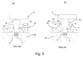
- Fig. 3 a illustrates a schematic view of a prior art bone anchored hearing aid system 34.
- the prior art bone anchored hearing aid system 34 is connected to a hearing aid abutment 8 that penetrates the skin 28 of the user of a hearing aid device 2.
- the hearing aid abutment 8 is connected to a fixture 4 that is anchored in the skull bone 26 of the user by means of a threaded portion 6.
- the hearing aid device 2 is mechanically attached to a coupling 30 that may comprise gripping jaws 30' which are adapted for a mechanical attachment to the abutment 8.
- a coupling 30 may comprise gripping jaws 30' which are adapted for a mechanical attachment to the abutment 8.
- gripping jaws 30' which are adapted for a mechanical attachment to the abutment 8.
- Various jaw formats are available at the market, and they are not shown in further detail here.
- Fig. 3 b illustrates a schematic view of the bone anchored hearing aid system 34 shown in Fig. 3 a) .
- the bone anchored hearing aid system 34 comprises a hearing aid abutment 8 that is surrounded by skin tissue 28' whish has swollen due to hypotrophy or other disorder.
- a tissue growth like the one illustrated in Fig. 3 b) typically may occur as a consequence of inflammation or infection in the skin tissue surrounding the abutment 8.
- Swollen scars 28' like the swollen skin tissue 28' indicated in Fig. 3 b) occur when the body overproduces collagen, which causes the scar 28' to be raised above the surrounding skin 28.
- the swollen skin tissue 28' has risen to such a level above the surrounding skin 28 that the skin tissue 28' interferes with the coupling 30 and the sound processor (not shown) in the hearing aid device 2. Accordingly, the abutment 8 needs to be exchanged in order to make the hearing aid device 2 work properly.
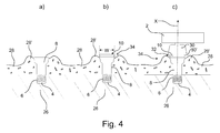
- Fig. 4 a illustrates a schematic view of a bone anchored hearing aid abutment 8 surrounded by swollen skin tissue 28'.
- the skin tissue 28' is approximately twice as thick as the remaining portion of the skin 28.
- the abutment 8 is mechanically attached to an anchored fixture 4 provided with a threaded portion 6.
- the fixture 4 is anchored into the skull bone 26 of a user of a hearing aid.
- Fig. 4 b) illustrates a schematic view of a thin extension member 10 according to the invention mounted on the bone anchored hearing aid abutment 8 shown in Fig. 4 a) .
- the extension member 10 has the same width, W, as the proximal portion of the abutment 8.
- Fig. 4 c illustrates a schematic view of a hearing aid device 2 mechanically attached to the bone anchored hearing aid abutment 8 shown in Fig. 4 b) via a coupling 30.
- the coupling 30 is attached to the extension member 10 that is mechanically attached to the abutment 8.
- the abutment 8 is fixed to the anchored fixture 4 provided with a threaded portion 6.
- the fixture 4 is anchored into the skull bone 26.
- the extension member 10 When the extension member 10 is attached to the abutment 8, the coupling 30 and thus the hearing aid device 2 is displaced along the longitudinal axis X of the abutment 8. Thus, a gap 32 is provided between the skin tissue 28' and the coupling 30.
- the swollen or swollen skin tissue 28' will not interfere with the coupling 30 or the processor in the hearing aid device 2. Accordingly, the extension member 10 makes it possible to keep applying the hearing aid device 2 and the existing abutment 8 despite the existence of the skin tissue 28'.
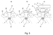
- Fig. 5 a illustrates a schematic view of a bone anchored hearing aid abutment 8 surrounded by a swollen or swollen skin tissue 28'.
- the swollen skin tissue 28' in fig. 5 is thicker than the swollen skin tissue 28' shown in Fig. 4 .
- the abutment 8 is mechanically attached to an anchored fixture 4 provided with a threaded portion 6.
- the fixture 4 is anchored into the skull bone 26 of a user of a hearing aid.
- Fig. 5 b illustrates a schematic view of a thick extension member 10 according to the invention.
- the extension member 10 is mounted on the bone anchored hearing aid abutment 8 shown in
- the extension member 10 has the same width, W, as the proximal portion of the abutment 8.
- Fig. 5 c illustrates a schematic view of a hearing aid device 2 that is mechanically fixed to the abutment 8 shown in Fig. 5 b) via a coupling 30.
- the coupling 30 is fixed to the extension member 10.
- the extension member 10 is mechanically attached to the abutment 8.
- the abutment 8 is fixed to the anchored fixture 4 provided with a threaded portion 6 and is anchored into the skull bone 26.
- Attaching the extension member 10 to the abutment 8 causes a displacement of the coupling 30.
- the hearing aid device 2 is moved along the longitudinal axis X of the abutment 8 and a gap 32 is established between the thickened skin tissue 28' and the coupling 30.
- the thickened skin tissue 28' will not interfere with the coupling 30 or the processor in the hearing aid device 2.
- an extension member 10 By using an extension member 10 according to the invention it is possible to keep applying the hearing aid device 2 and the existing abutment 8 despite the existence of thickened or swollen skin tissue 28'.
- the thickness of the extension member 10 may depend on the specific requirements.
- the thickness of the extension member 10 may by 1 mm or more, e.g. 2 mm by way of example.
- Fig. 6 a illustrates a schematic view of a hearing aid interconnection system 34 comprising a prior art bone anchored hearing aid abutment 8 surrounded by swollen skin tissue 28'.
- the thickness of the thickened skin tissue 28' exceeds the thickness of the remaining skin 28.
- the thickness of the thickened skin tissue 28' also exceeds the length L 1 of the abutment 8.
- the abutment 8 is attached to a fixture 4 provided with threads 6 and anchored to the skull bone 26 of a user of a hearing aid.
- the swollen or thickened skin tissue 28' surrounding the abutment 8 is in physical contact with the hearing aid device 2. Thus, there is a risk that the hearing aid device 2 will not function properly due to the presence of the swollen skin tissue 28'.
- FIG. 6 b illustrates a schematic view of a hearing aid interconnection system 34 comprising an extension member 10 according to the invention.
- the extension member 10 is mounted on a bone anchored hearing aid abutment 8 that is surrounded by thickened skin tissue 28' corresponding to the one shown in Fig. 6a ).
- the extension member 10 is mechanically attached to the abutment 8 and the abutment 8 is fixed to an anchored fixture 4 provided with a threaded portion 6 and is anchored into the skull bone 26.
- the coupling 30 When the extension member 10 is attached to the abutment 8 the coupling 30 is displaced a distance, D, along the longitudinal axis X of the abutment 8. Thus, a gap 32 is established between the thickened skin tissue 28' and the hearing aid device 2.
- the length of the abutment 8 and the attached extension member 10 is L 2
- the length of the abutment 8 is L 1 .
- the thickened skin tissue 28' will not interfere with the hearing aid device 2.
- the thickness of the extension member 10 may depend on the specific requirements.
- the thickness of the extension member 10 may by 1 mm or more, e.g. 2 mm by way of example so that the distance D that the extension member 10 extends the abutment 8 along the longitudinal axis X of the abutment 8 is 1 mm or more.
Landscapes
- Health & Medical Sciences (AREA)
- General Health & Medical Sciences (AREA)
- Otolaryngology (AREA)
- Engineering & Computer Science (AREA)
- Neurosurgery (AREA)
- Physics & Mathematics (AREA)
- Acoustics & Sound (AREA)
- Signal Processing (AREA)
- Details Of Audible-Bandwidth Transducers (AREA)
- Computer Networks & Wireless Communication (AREA)
- Surgical Instruments (AREA)
- Prostheses (AREA)
Priority Applications (1)
| Application Number | Priority Date | Filing Date | Title |
|---|---|---|---|
| EP16186132.3A EP3131312A1 (de) | 2013-11-25 | 2013-11-25 | Hörgeräteverbindungssystem |
Applications Claiming Priority (2)
| Application Number | Priority Date | Filing Date | Title |
|---|---|---|---|
| EP16186132.3A EP3131312A1 (de) | 2013-11-25 | 2013-11-25 | Hörgeräteverbindungssystem |
| EP13194281.5A EP2876901B1 (de) | 2013-11-25 | 2013-11-25 | Hörgerät-Verbindungssystem |
Related Parent Applications (2)
| Application Number | Title | Priority Date | Filing Date |
|---|---|---|---|
| EP13194281.5A Division EP2876901B1 (de) | 2013-11-25 | 2013-11-25 | Hörgerät-Verbindungssystem |
| EP13194281.5A Previously-Filed-Application EP2876901B1 (de) | 2013-11-25 | 2013-11-25 | Hörgerät-Verbindungssystem |
Publications (1)
| Publication Number | Publication Date |
|---|---|
| EP3131312A1 true EP3131312A1 (de) | 2017-02-15 |
Family
ID=49622753
Family Applications (2)
| Application Number | Title | Priority Date | Filing Date |
|---|---|---|---|
| EP16186132.3A Withdrawn EP3131312A1 (de) | 2013-11-25 | 2013-11-25 | Hörgeräteverbindungssystem |
| EP13194281.5A Active EP2876901B1 (de) | 2013-11-25 | 2013-11-25 | Hörgerät-Verbindungssystem |
Family Applications After (1)
| Application Number | Title | Priority Date | Filing Date |
|---|---|---|---|
| EP13194281.5A Active EP2876901B1 (de) | 2013-11-25 | 2013-11-25 | Hörgerät-Verbindungssystem |
Country Status (5)
| Country | Link |
|---|---|
| US (3) | US9241225B2 (de) |
| EP (2) | EP3131312A1 (de) |
| CN (1) | CN104661167B (de) |
| AU (1) | AU2014262222A1 (de) |
| DK (1) | DK2876901T3 (de) |
Families Citing this family (9)
| Publication number | Priority date | Publication date | Assignee | Title |
|---|---|---|---|---|
| US9736601B2 (en) | 2012-07-16 | 2017-08-15 | Sophono, Inc. | Adjustable magnetic systems, devices, components and methods for bone conduction hearing aids |
| US9210521B2 (en) | 2012-07-16 | 2015-12-08 | Sophono, Inc. | Abutment attachment systems, mechanisms, devices, components and methods for bone conduction hearing aids |
| US9526810B2 (en) | 2011-12-09 | 2016-12-27 | Sophono, Inc. | Systems, devices, components and methods for improved acoustic coupling between a bone conduction hearing device and a patient's head or skull |
| US9179228B2 (en) | 2011-12-09 | 2015-11-03 | Sophono, Inc. | Systems devices, components and methods for providing acoustic isolation between microphones and transducers in bone conduction magnetic hearing aids |
| US9258656B2 (en) | 2011-12-09 | 2016-02-09 | Sophono, Inc. | Sound acquisition and analysis systems, devices and components for magnetic hearing aids |
| US20140179985A1 (en) | 2012-12-21 | 2014-06-26 | Marcus ANDERSSON | Prosthesis adapter |
| EP3149967B1 (de) | 2014-05-27 | 2020-10-28 | Sophono, Inc. | Systeme, vorrichtungen, komponenten und verfahren zur verringerung der rückkopplung zwischen mikrofonen und wandlern in magnetischen knochenleitungshörgeräten |
| WO2017078720A1 (en) | 2015-11-05 | 2017-05-11 | Advanced Bionics Ag | Implantable medical devices having resilient mounting tabs and associated methods |
| EP4362497A1 (de) * | 2022-10-27 | 2024-05-01 | Oticon Medical A/S | Einteilige kupplung für ein knochenverankertes hörsystem |
Citations (5)
| Publication number | Priority date | Publication date | Assignee | Title |
|---|---|---|---|---|
| US20100137675A1 (en) * | 2008-03-31 | 2010-06-03 | Cochlear Limited | Bone conduction devices generating tangentially-directed mechanical force using a rotationally moving mass |
| US20120172658A1 (en) * | 2009-08-13 | 2012-07-05 | Goran Bjorn | Medical implant system |
| US20130041206A1 (en) * | 2010-02-10 | 2013-02-14 | Marcus ANDERSSON | Epidermal down-growth barrier |
| US20130090518A1 (en) * | 2011-10-11 | 2013-04-11 | Göran Björn | Bone conduction implant |
| WO2014097266A2 (en) * | 2012-12-21 | 2014-06-26 | Cochlear Limited | Prosthesis adapter |
Family Cites Families (17)
| Publication number | Priority date | Publication date | Assignee | Title |
|---|---|---|---|---|
| US5460593A (en) * | 1993-08-25 | 1995-10-24 | Audiodontics, Inc. | Method and apparatus for imparting low amplitude vibrations to bone and similar hard tissue |
| SE503790C2 (sv) | 1994-12-02 | 1996-09-02 | P & B Res Ab | Urkopplingsanordning för implantatkoppling vid hörapparat |
| SE503791C2 (sv) * | 1994-12-02 | 1996-09-02 | P & B Res Ab | Anordning vid hörapparat |
| US7160244B2 (en) * | 2004-05-10 | 2007-01-09 | Patrik Westerkull | Arrangement for a hearing aid |
| US7021676B2 (en) * | 2004-05-10 | 2006-04-04 | Patrik Westerkull | Connector system |
| US7376237B2 (en) * | 2004-09-02 | 2008-05-20 | Oticon A/S | Vibrator for bone-conduction hearing |
| US7065223B2 (en) * | 2004-09-09 | 2006-06-20 | Patrik Westerkull | Hearing-aid interconnection system |
| US7538463B2 (en) * | 2006-01-10 | 2009-05-26 | Citizen Electronics Co., Ltd. | Vibrator |
| JP2007275776A (ja) * | 2006-04-06 | 2007-10-25 | Citizen Electronics Co Ltd | 振動体 |
| DE102007008551A1 (de) | 2007-02-21 | 2008-09-04 | Siemens Audiologische Technik Gmbh | Hörvorrichtung mit magnetisch befestigtem Batteriefach |
| SE531178C2 (sv) * | 2007-05-24 | 2009-01-13 | Cochlear Ltd | Förankringselement för permanent förankring av extraorala proteser |
| EP2178479B1 (de) * | 2007-07-20 | 2015-06-17 | Cochlear Americas | Kupplungsgerät für ein in knochen verankertes hörgerät |
| DK2083582T3 (da) * | 2008-01-28 | 2013-11-11 | Oticon Medical As | Knogleledende høreapparat med forbindelse |
| DE102009014771A1 (de) * | 2009-03-25 | 2010-09-30 | Cochlear Ltd., Lane Cove | Hörhilfeimplantat |
| EP2252079A1 (de) * | 2009-05-14 | 2010-11-17 | Oticon A/S | Knochenverankerte knochenleitende Hörhilfe |
| US9179228B2 (en) | 2011-12-09 | 2015-11-03 | Sophono, Inc. | Systems devices, components and methods for providing acoustic isolation between microphones and transducers in bone conduction magnetic hearing aids |
| US10757516B2 (en) | 2013-10-29 | 2020-08-25 | Cochlear Limited | Electromagnetic transducer with specific interface geometries |
-
2013
- 2013-11-25 EP EP16186132.3A patent/EP3131312A1/de not_active Withdrawn
- 2013-11-25 EP EP13194281.5A patent/EP2876901B1/de active Active
- 2013-11-25 DK DK13194281.5T patent/DK2876901T3/en active
-
2014
- 2014-11-12 AU AU2014262222A patent/AU2014262222A1/en not_active Abandoned
- 2014-11-21 US US14/550,238 patent/US9241225B2/en not_active Expired - Fee Related
- 2014-11-24 CN CN201410683245.9A patent/CN104661167B/zh active Active
-
2015
- 2015-12-10 US US14/965,438 patent/US9571947B2/en active Active
-
2017
- 2017-01-05 US US15/399,216 patent/US20170118566A1/en not_active Abandoned
Patent Citations (5)
| Publication number | Priority date | Publication date | Assignee | Title |
|---|---|---|---|---|
| US20100137675A1 (en) * | 2008-03-31 | 2010-06-03 | Cochlear Limited | Bone conduction devices generating tangentially-directed mechanical force using a rotationally moving mass |
| US20120172658A1 (en) * | 2009-08-13 | 2012-07-05 | Goran Bjorn | Medical implant system |
| US20130041206A1 (en) * | 2010-02-10 | 2013-02-14 | Marcus ANDERSSON | Epidermal down-growth barrier |
| US20130090518A1 (en) * | 2011-10-11 | 2013-04-11 | Göran Björn | Bone conduction implant |
| WO2014097266A2 (en) * | 2012-12-21 | 2014-06-26 | Cochlear Limited | Prosthesis adapter |
Also Published As
| Publication number | Publication date |
|---|---|
| AU2014262222A1 (en) | 2015-06-11 |
| DK2876901T3 (en) | 2016-12-19 |
| US9571947B2 (en) | 2017-02-14 |
| US9241225B2 (en) | 2016-01-19 |
| US20160100264A1 (en) | 2016-04-07 |
| US20170118566A1 (en) | 2017-04-27 |
| CN104661167B (zh) | 2019-08-16 |
| US20150146902A1 (en) | 2015-05-28 |
| CN104661167A (zh) | 2015-05-27 |
| EP2876901A1 (de) | 2015-05-27 |
| EP2876901B1 (de) | 2016-09-14 |
Similar Documents
| Publication | Publication Date | Title |
|---|---|---|
| EP2876901B1 (de) | Hörgerät-Verbindungssystem | |
| US12490034B2 (en) | Bone conduction implant | |
| EP2178479B1 (de) | Kupplungsgerät für ein in knochen verankertes hörgerät | |
| CA2661500C (en) | Dental superstructure, and a method of manufacture thereof | |
| EP1799104B1 (de) | Hörhilfe-verbindungssystem | |
| US10334374B2 (en) | Prosthesis adapter | |
| US20070009853A1 (en) | Implant device | |
| EP2907473B1 (de) | Gaumenimplantat für eine deckprothese | |
| WO2018017331A1 (en) | Denture retaining bar and system | |
| US11389180B2 (en) | Bone fixture for a medical prosthesis | |
| CN216702677U (zh) | 种植体组件 | |
| CN113509297B (zh) | 一种组合式骨整合系统 | |
| JP5514991B2 (ja) | インプラント | |
| CN108542481A (zh) | 一种颧骨骨折外固定愈合用面具及固定愈合系统 | |
| US20230165615A1 (en) | Torque limiting drive tools |
Legal Events
| Date | Code | Title | Description |
|---|---|---|---|
| PUAI | Public reference made under article 153(3) epc to a published international application that has entered the european phase |
Free format text: ORIGINAL CODE: 0009012 |
|
| AC | Divisional application: reference to earlier application |
Ref document number: 2876901 Country of ref document: EP Kind code of ref document: P |
|
| AK | Designated contracting states |
Kind code of ref document: A1 Designated state(s): AL AT BE BG CH CY CZ DE DK EE ES FI FR GB GR HR HU IE IS IT LI LT LU LV MC MK MT NL NO PL PT RO RS SE SI SK SM TR |
|
| STAA | Information on the status of an ep patent application or granted ep patent |
Free format text: STATUS: THE APPLICATION IS DEEMED TO BE WITHDRAWN |
|
| 18D | Application deemed to be withdrawn |
Effective date: 20170817 |