EP3131453B1 - Tragbare plattform zur messung der gehirnaktivität zur beurteilung von sichtfelddefiziten - Google Patents
Tragbare plattform zur messung der gehirnaktivität zur beurteilung von sichtfelddefiziten Download PDFInfo
- Publication number
- EP3131453B1 EP3131453B1 EP15780001.2A EP15780001A EP3131453B1 EP 3131453 B1 EP3131453 B1 EP 3131453B1 EP 15780001 A EP15780001 A EP 15780001A EP 3131453 B1 EP3131453 B1 EP 3131453B1
- Authority
- EP
- European Patent Office
- Prior art keywords
- visual
- user
- visual field
- electrodes
- subject
- Prior art date
- Legal status (The legal status is an assumption and is not a legal conclusion. Google has not performed a legal analysis and makes no representation as to the accuracy of the status listed.)
- Active
Links
Images




Classifications
-
- A—HUMAN NECESSITIES
- A61—MEDICAL OR VETERINARY SCIENCE; HYGIENE
- A61B—DIAGNOSIS; SURGERY; IDENTIFICATION
- A61B3/00—Apparatus for testing the eyes; Instruments for examining the eyes
- A61B3/02—Subjective types, i.e. testing apparatus requiring the active assistance of the patient
- A61B3/024—Subjective types, i.e. testing apparatus requiring the active assistance of the patient for determining the visual field, e.g. perimeter types
-
- A—HUMAN NECESSITIES
- A61—MEDICAL OR VETERINARY SCIENCE; HYGIENE
- A61B—DIAGNOSIS; SURGERY; IDENTIFICATION
- A61B5/00—Measuring for diagnostic purposes; Identification of persons
- A61B5/24—Detecting, measuring or recording bioelectric or biomagnetic signals of the body or parts thereof
- A61B5/316—Modalities, i.e. specific diagnostic methods
- A61B5/369—Electroencephalography [EEG]
- A61B5/377—Electroencephalography [EEG] using evoked responses
- A61B5/378—Visual stimuli
-
- A—HUMAN NECESSITIES
- A61—MEDICAL OR VETERINARY SCIENCE; HYGIENE
- A61B—DIAGNOSIS; SURGERY; IDENTIFICATION
- A61B3/00—Apparatus for testing the eyes; Instruments for examining the eyes
- A61B3/0016—Operational features thereof
- A61B3/0025—Operational features thereof characterised by electronic signal processing, e.g. eye models
-
- A—HUMAN NECESSITIES
- A61—MEDICAL OR VETERINARY SCIENCE; HYGIENE
- A61B—DIAGNOSIS; SURGERY; IDENTIFICATION
- A61B3/00—Apparatus for testing the eyes; Instruments for examining the eyes
- A61B3/0016—Operational features thereof
- A61B3/0041—Operational features thereof characterised by display arrangements
- A61B3/005—Constructional features of the display
-
- A—HUMAN NECESSITIES
- A61—MEDICAL OR VETERINARY SCIENCE; HYGIENE
- A61B—DIAGNOSIS; SURGERY; IDENTIFICATION
- A61B3/00—Apparatus for testing the eyes; Instruments for examining the eyes
- A61B3/0091—Fixation targets for viewing direction
-
- A—HUMAN NECESSITIES
- A61—MEDICAL OR VETERINARY SCIENCE; HYGIENE
- A61B—DIAGNOSIS; SURGERY; IDENTIFICATION
- A61B3/00—Apparatus for testing the eyes; Instruments for examining the eyes
- A61B3/10—Objective types, i.e. instruments for examining the eyes independent of the patients' perceptions or reactions
- A61B3/113—Objective types, i.e. instruments for examining the eyes independent of the patients' perceptions or reactions for determining or recording eye movement
-
- A—HUMAN NECESSITIES
- A61—MEDICAL OR VETERINARY SCIENCE; HYGIENE
- A61B—DIAGNOSIS; SURGERY; IDENTIFICATION
- A61B3/00—Apparatus for testing the eyes; Instruments for examining the eyes
- A61B3/10—Objective types, i.e. instruments for examining the eyes independent of the patients' perceptions or reactions
- A61B3/14—Arrangements specially adapted for eye photography
- A61B3/145—Arrangements specially adapted for eye photography by video means
-
- A—HUMAN NECESSITIES
- A61—MEDICAL OR VETERINARY SCIENCE; HYGIENE
- A61B—DIAGNOSIS; SURGERY; IDENTIFICATION
- A61B5/00—Measuring for diagnostic purposes; Identification of persons
- A61B5/16—Devices for psychotechnics; Testing reaction times ; Devices for evaluating the psychological state
- A61B5/161—Flicker fusion testing
-
- A—HUMAN NECESSITIES
- A61—MEDICAL OR VETERINARY SCIENCE; HYGIENE
- A61B—DIAGNOSIS; SURGERY; IDENTIFICATION
- A61B5/00—Measuring for diagnostic purposes; Identification of persons
- A61B5/16—Devices for psychotechnics; Testing reaction times ; Devices for evaluating the psychological state
- A61B5/163—Devices for psychotechnics; Testing reaction times ; Devices for evaluating the psychological state by tracking eye movement, gaze, or pupil change
-
- A—HUMAN NECESSITIES
- A61—MEDICAL OR VETERINARY SCIENCE; HYGIENE
- A61B—DIAGNOSIS; SURGERY; IDENTIFICATION
- A61B5/00—Measuring for diagnostic purposes; Identification of persons
- A61B5/24—Detecting, measuring or recording bioelectric or biomagnetic signals of the body or parts thereof
- A61B5/25—Bioelectric electrodes therefor
- A61B5/279—Bioelectric electrodes therefor specially adapted for particular uses
- A61B5/291—Bioelectric electrodes therefor specially adapted for particular uses for electroencephalography [EEG]
-
- A—HUMAN NECESSITIES
- A61—MEDICAL OR VETERINARY SCIENCE; HYGIENE
- A61B—DIAGNOSIS; SURGERY; IDENTIFICATION
- A61B5/00—Measuring for diagnostic purposes; Identification of persons
- A61B5/24—Detecting, measuring or recording bioelectric or biomagnetic signals of the body or parts thereof
- A61B5/316—Modalities, i.e. specific diagnostic methods
- A61B5/369—Electroencephalography [EEG]
- A61B5/372—Analysis of electroencephalograms
-
- A—HUMAN NECESSITIES
- A61—MEDICAL OR VETERINARY SCIENCE; HYGIENE
- A61B—DIAGNOSIS; SURGERY; IDENTIFICATION
- A61B5/00—Measuring for diagnostic purposes; Identification of persons
- A61B5/24—Detecting, measuring or recording bioelectric or biomagnetic signals of the body or parts thereof
- A61B5/316—Modalities, i.e. specific diagnostic methods
- A61B5/398—Electrooculography [EOG], e.g. detecting nystagmus; Electroretinography [ERG]
-
- A—HUMAN NECESSITIES
- A61—MEDICAL OR VETERINARY SCIENCE; HYGIENE
- A61B—DIAGNOSIS; SURGERY; IDENTIFICATION
- A61B5/00—Measuring for diagnostic purposes; Identification of persons
- A61B5/68—Arrangements of detecting, measuring or recording means, e.g. sensors, in relation to patient
- A61B5/6801—Arrangements of detecting, measuring or recording means, e.g. sensors, in relation to patient specially adapted to be attached to or worn on the body surface
- A61B5/6802—Sensor mounted on worn items
- A61B5/6803—Head-worn items, e.g. helmets, masks, headphones or goggles
Definitions
- This patent document relates to systems, devices, and processes that use brain machine interface (BMI) technologies.
- BMI brain machine interface
- Electroencephalography is the recording of electrical activity exhibited by the brain using electrodes positioned on a subject's scalp, forming a spectral content of neural signal oscillations that comprise an EEG data set.
- the electrical activity of the brain that is detected by EEG techniques can include voltage fluctuations, e.g., resulting from ionic current flows within the neurons of the brain.
- EEG refers to the recording of the brain's spontaneous electrical activity over a short period of time, e.g., less than an hour.
- EEG can be used in clinical diagnostic applications including epilepsy, coma, encephalopathies, brain death, and other diseases and defects, as well as in studies of sleep and sleep disorders.
- EEG has been used for the diagnosis of tumors, stroke and other focal brain disorders.
- US 2009/0091706 describes a method for determining a likelihood of a visual deficit in a subject using a simultaneously multi-temporal visual test. At least two visual patterns are simultaneously displayed to the subject. Each pattern reverses in contrast or color at a different display frequency, and each pattern is displayed to a different region of the subject's visual field. Electrical activity of the brain of the subject is captured and sampled, and one or more frequency components are resolved from the resulting signal, where each frequency component corresponds to a different display frequency. The method then involves determining from the frequency components, optionally by comparison between the eyes, a measurement of a likelihood that a visual deficit exists in a particular area.
- EEG electroencephalogram
- mfSSVEP multifocal steady-state visual-evoked potentials
- the disclosed techniques integrate mfSSVEPs into a portable platform using wireless EEG and a head mounted display, demonstrating ability to assess potential visual field deficits, e.g., in conditions such as glaucoma.
- a system for monitoring brain activity associated with visual field of a user includes a sensor unit to acquire electroencephalogram (EEG) signals including one or more electrodes attached to a casing wearable on the head of a user; visual display unit including a display screen to present visual stimuli to the user in a plurality of sectors of a visual field, in which the presented visual stimuli includes an optical flickering effect at a selected frequency mapped to each sector of the visual field, the visual stimuli configured to evoke multifocal steady-state visual-evoked potentials (mfSSVEP) in the EEG signals exhibited by the user acquired by the sensor unit; and a data processing unit in communication with the sensor unit and the visual display unit to analyze the acquired EEG signals and produce an assessment of the user's visual field.
- EEG electroencephalogram
- a method for examining a visual field of a subject includes presenting, to a subject, visual stimuli in a plurality of sectors of a visual field of a subject, in which for each sector the presented visual stimuli includes an optical flickering effect at a selected frequency; acquiring electroencephalogram (EEG) signals from one or more electrodes in contact with the head of the subject; processing the acquired EEG signals to extract multifocal steady-state visual-evoked potentials (mfSSVEP) data associated with the subject's EEG signal response to the presented visual stimuli; and producing a quantitative assessment of the visual field of the subject based on the MfSSVEP data.
- EEG electroencephalogram
- mfSSVEP multifocal steady-state visual-evoked potentials
- a portable system for monitoring brain activity associated with visual field of a user includes a brain signal sensor device to acquire electroencephalogram (EEG) signals including one or more electrodes attached to a casing wearable on the head of a user; a wearable visual display unit to present visual stimuli to the user and structured to include a display screen and a casing able to secure to the head of the user, in which the wearable visual display is operable to present the visual stimuli in a plurality of sectors of the user's visual field, such that for each sector the presented visual stimuli includes an optical flickering effect at a selected frequency, and in which the visual stimuli are configured to evoke multifocal steady-state visual-evoked potentials (mfSSVEP) in the EEG signals exhibited by the user acquired by the brain signal sensor device; a data processing unit in communication with the brain signal sensor device and the wearable visual display unit to provide the visual stimuli to the wearable visual display unit and to analyze the acquired EEG signals and produce an assessment of the user's visual field
- the disclosed portable platform for assessing functional loss can facilitate detection and monitoring of visual field loss in glaucoma, the leading cause of blindness in the world.
- the disclosed portable platform uses high-density EEG recording and mfSSVEP that can provide improved signal-to-noise ratios, increasing reproducibility and diagnostic accuracy, e.g., as compared to existing EEG-based methods for objective perimetry, such as mfVEP.
- the disclosed methods can allow for much broader and more frequent testing of patients, e.g., as compared to existing perimetric approaches. For example, this could reduce the number of office visits necessary for patients at risk or diagnosed with glaucoma, significantly decreasing the economic burden of the disease.
- the disclosed methods can facilitate the discrimination of true deterioration from test-retest variability, e.g., resulting in earlier diagnosis and detection of progression.
- the disclosed portably-implemented and objective methods for visual field assessment can also allow screening for visual loss in underserved populations.
- the disclosed technology is non-invasive and can be implemented without direct physical contact with an eye of the individual subject being assessed, and thereby avoid causing any discomfort or risk of injury through inadvertent application of force or transfer of harmful chemical or biological material to the eye.
- Optic neuropathy refers to optic nerve damage that can result in significant and irreversible loss of visual function and disability.
- Glaucoma is associated with a progressive degeneration of retinal ganglion cells (RGCs) and their axons, resulting in a characteristic appearance of the optic disc and a concomitant pattern of visual field loss.
- RRCs retinal ganglion cells
- Loss of visual function in glaucoma is generally irreversible, and without adequate treatment the disease can progress to disability and blindness. The disease can remain relatively asymptomatic until late stages and, therefore, early detection and monitoring of functional damage is paramount to prevent functional impairment and blindness.
- glaucoma affects more than 70 million individuals worldwide with approximately 10% being bilaterally blind, which makes it the leading cause of irreversible blindness in the world.
- the number of affected individuals is likely to be much larger than the number known to have it.
- Population-level survey data indicate that only 10% to 50% of the individuals are aware they have glaucoma.
- Visual dysfunction appears to be a strong predictor of cognitive dysfunction in subject in a number of clinical neuroscience disorders.
- the functional deficits of glaucoma and Alzheimer's Disease include loss in low spatial frequency ranges in contrast sensitivity, and are similar in both diseases.
- Pattern masking has been found to be a good predictor of cognitive performance in numerous standard cognitive tests. Some tests found to correlate with pattern masking include Gollin, Stroop-Work, WAIS-PA, Stroop-Color, Geo-Complex Copy, Stroop-Mixed and RCPM, for example. Losses in contrast sensitivity at the lowest spatial frequency also was predictive of cognitive losses in the seven tests. For example, AD subjects have abnormal word reading thresholds corresponding to their severity of cognitive impairment and reduced contrast sensitivity in all spatial frequencies as compared to normal subjects.
- SAP standard automated perimetry
- Visual field assessment with SAP requires considerable subjective input from the patient, and for some patients it is very difficult, or even impossible, to obtain reliable visual field measures.
- SAP is also limited by large test-retest variability and a large number of tests are usually necessary in order to discriminate true disease progression from noise, even for reliable test-takers.
- SAP testing is limited by subjectivity of patient responses and large variability, frequently requiring a large number of tests for effective detection of change over time. These tests are generally conducted in clinic-based settings and, due to limited patient availability and health care resources, an insufficient number of tests are frequently acquired over time, resulting in delayed diagnosis and detection of disease progression.
- SAP testing is generally performed in a clinic-based setting and requires highly trained technicians, this limits the availability of this testing resource, which frequently results in patients not undergoing the necessary number of tests to allow detection of disease progression over time, and thereby resulting in late diagnosis or delayed detection of progression.
- Perimeters are also usually expensive and not easily transportable, which has largely impeded the use of the SAP technique for screening or assessment of visual field loss in remote settings and in underserved populations.
- Neurological disorders e.g., such as macular degeneration, diabetic retinopathy, optic neuritis, papilledema, anterior ischemic optic neuropathy, and tumor, can be diagnosed and tracked by SAP.
- VEP visual evoked potential
- multifocal VEP techniques have been limited by relatively low signal to noise ratio and have shown limited potential to assess visual field losses in the disease.
- the conventional pattern VEP is predominantly generated by cortical elements receiving projections from the central retina, where the central 2° of visual field contributes 65% of the response. Therefore, conventional VEP possesses a limited ability to reflect field loss in non-central areas, such as those that can occur with glaucoma.
- VEP techniques can allow many areas of the retina to be stimulated simultaneously and separate responses from each part of the visual field to be obtained, individual differences in the anatomy of the visual cortex lead to considerable inter-individual variability of responses in normal subjects, making it difficult the identification of mfVEP abnormalities in diseased patients.
- existing mfVEP recording techniques can only be performed with non-portable devices in clinic- or laboratory-based settings, requiring cumbersome setup for placement of electrodes (e.g., data collection requires skin preparation and gel application to ensure good electrical conductivity between sensor and skin), and such procedures are time consuming and uncomfortable for the patient.
- the present technology includes methods, systems, and devices that acquire, process, and/or utilize steady-state visually evoked potentials (SSVEP) for monitoring, tracking, and/or diagnosing various paradigms in cognitive function (e.g., visual attention, binocular rivalry, working memory, and brain rhythms) and clinical neuroscience (e.g., aging, neurodegenerative disorders, schizophrenia, ophthalmic pathologies, migraine, autism, depression, anxiety, stress, and epilepsy), particularly for SSVEPs generated by optical stimuli.
- cognitive function e.g., visual attention, binocular rivalry, working memory, and brain rhythms
- clinical neuroscience e.g., aging, neurodegenerative disorders, schizophrenia, ophthalmic pathologies, migraine, autism, depression, anxiety, stress, and epilepsy
- EEG electroencephalogram
- the disclosed techniques integrate mfSSVEPs into a portable platform using wireless EEG and a head mounted display capable of assessing potential visual field deficits.
- the disclosed technology can be applied to diagnose and track neurological disorders, e.g., such as macular degeneration, diabetic retinopathy, optic neuritis, papilledema, anterior ischemic optic neuropathy, and/or tumors.
- the present technology utilizes rapid flickering stimulation to produce a brain response characterized by a "quasi-sinusoidal" waveform whose frequency components are constant in amplitude and phase, e.g., the so-called steady-state response.
- the portable platform integrates a wearable, wireless, high-density dry EEG system and a head-mounted display allowing users to routinely monitor the electrical brain activity associated with visual field stimulation.
- the present technology includes brain-computer interfaces using dry EEG sensor arrays, wearable/wireless data acquisition and signal processing hardware and software. These interfaces can monitor and record non-invasive, high spatiotemporal resolution brain activity of unconstrained, actively engaged human subjects.
- the disclosed technology can be applied for ophthalmologic diagnosis of neurological complications, in particular that of major ocular pathologies including glaucoma, retinal anomalies and of sight, retinal degeneration of the retinal structure and macular degeneration, diabetic retinopathy, optic neuritis, optical neuroma, or degenerative diseases, e.g., such as Parkinson's disease, Alzheimer's disease, non-Alzheimer's dementia, multiple sclerosis, ALS, head trauma, diabetes, or other cognitive disorders, e.g., such as dyslexia. More broadly, the present technology can be used to characterize inappropriate responses to contrast sensitivity patterns, and disorders affecting the optical nerve and the visual cortex.
- degenerative diseases e.g., such as Parkinson's disease, Alzheimer's disease, non-Alzheimer's dementia, multiple sclerosis, ALS, head trauma, diabetes, or other cognitive disorders, e.g., such as dyslexia.
- the present technology can be used to characterize inappropriate responses to contrast sensitivity patterns,
- the disclosed technology can be used for multiple sclerosis (MS). It is known that MS affects neurons and that the effect comes and goes with time. There is apparent recovery of the cells at least in early stages of the disease. One would therefore expect the diagnosed areas of loss in the visual field to move around the visual field over time, and perhaps to recovery temporarily. As the disease progresses to the point where there is a lot of loss on the retina, the areas of loss will remain lost and will not show temporary recovery.
- the retina and brain do parallel processing to determine relative position of adjacent objects. In the case of dyslexia, for example, this processing somehow gets reversed and the subject mixes up the order of letters in words or even the order of entire words. This too could show up as an apparent ganglion cell loss.
- the disclosed technology includes portable platforms that can be used for accurate and convenient screening of many neuro-degenerative diseases, e.g., including Alzheimer's, non-Alzheimer's dementia, Parkinson's, multiple sclerosis, macular degeneration, ALS, diabetes, dyslexia, head trauma, and others.
- neuro-degenerative diseases e.g., including Alzheimer's, non-Alzheimer's dementia, Parkinson's, multiple sclerosis, macular degeneration, ALS, diabetes, dyslexia, head trauma, and others.
- the present technology utilizes electroencephalogram (EEG)-based brain sensing methods, systems, and devices for visual-field examination by using high-density EEG to associate the dynamics of multifocal steady-state visual-evoked potentials (mfSSVEP) with visual field defects, in which the use of rapid flickering stimulation can produce a brain response characterized by a "quasi-sinusoidal" waveform whose frequency components are constant in amplitude and phase, the so-called steady-state response.
- EEG electroencephalogram
- mfSSVEP multifocal steady-state visual-evoked potentials
- Steady-state VEPs have desirable properties for use in the assessment of the integrity of the visual system.
- mfSSVEP is a form of steady-state visual-evoked potentials which reflect a frequency-tagged oscillatory EEG activity modulated by the frequency of periodic visual simulation higher than 6 Hz.
- the mfSSVEP is a signal of multi-frequency tagged SSVEP, e.g., which can be elicited by simultaneously presenting multiple continuous, repetitive black/white reversing visual patches flickering at different frequencies.
- a flicker sector(s) corresponding to a visual field deficit(s) will be less perceivable or unperceivable and thereby will elicit a weaker SSVEP, e.g., as compared to the brain responses to other visual stimuli presented at normal visual spots.
- the disclosed methods, systems, and devices for visual-field examination using mfSSVEP data includes the formation of a spatial visual stimulus display having multiple regions or sectors at different spatial locations, where for each region, the particular region includes an optical effect (e.g., light flickering) that changes at a unique frequency with respect to at least a proximate region or any other region of the visual stimulus display.
- the visual stimulus display can include twenty regions each presenting its respective optical effect at a different frequency between 8.0 Hz and 11.8 Hz (e.g., 8.0 in sector 1, 8.2 in sector 2, 8.4 in sector 3, ..., 11.8 in sector 20).
- the optical effect can be a light modulating between an ON and OFF state at the designated frequency for the particular region.
- the brain response to the visual stimuli e.g., as measured by at least one electrode placed on or near the head or multiple electrodes arranged in an arrangement to improve spatiotemporal resolution of the EEG signals, are acquired and processed to produce and evaluate mfSSVEP data with respect to a frequency spectrum including the designated frequencies mapped to the spatial regions of the visual stimulus display.
- the processing includes comparing the mfSSVEP signal at the particular frequencies to a predetermined threshold, or in relation to other mfSSVEP signals, to determine if the signal falls below the predetermined threshold or is substantially lower with respect to a comparative mfSSVEP signal.
- Determination of a mfSSVEP signal below the threshold or substantially lower than a standard at that particular frequency corresponds to a visual field deficiency to the spatial location on the visual stimulus display to which that frequency is mapped, and indicative of a visual field defect of the user in that specific region.
- the disclosed techniques include using SSVEP and brain-computer interfaces (BCIs) to bridge the human brain with computers or external devices.
- BCIs brain-computer interfaces
- the users of SSVEP-based brain-computer interface can interact with or control external devices and/or environments through gazing at distinct frequency-coded targets.
- the SSVEP-based BCI can provide a promising communication carrier for patients with disabilities due to its high signal-to-noise ratio over the visual cortex, which can be measured by EEG at the parieto-occipital region noninvasively.
- Methods, devices and systems of the disclosed technology can implement wireless SSVEP data acquisition and processing.
- Methods, devices and systems of the disclosed technology can include a noninvasive platform for continuously monitoring high temporal resolution brain dynamics without requiring conductive gels applied to the scalp.
- An exemplary system can employ dry microelectromechanical system EEG sensors, low-power signal acquisition, amplification and digitization, wireless telemetry, and real-time processing.
- the present technology can include analytical techniques, such as independent component analysis, which can improve detectability of SSVEP signals.
- mfSSVEP multifocal techniques to SSVEP
- mfSSVEP multifocal techniques to SSVEP
- the exemplary results of such implementations demonstrate detection of localized and peripheral field losses, as well as show successful implementations of a portable objective method of assessment of visual field loss in opto-neurological diseases, e.g., such as glaucoma, amblyopia, age-related macular degeneration, and optic neuritis.
- a validated portable objective method for assessment of visual field loss would have numerous advantages compared to currently existing methods to assess functional loss in the disease.
- An objective EEG-based test would remove the subjectivity and decision-making involved when performing perimetry, potentially improving reliability of the test.
- a portable and objective test could be done quickly at home under unconstrained situations, decreasing the required number of office visits and the economic burden of the disease.
- a much larger number of tests could be obtained over time. This would greatly enhance the ability of separating true deterioration from measurement variability, potentially allowing more accurate and earlier detection of progression.
- more precise estimates of rates of progression could be obtained.
- the exemplary visual field assessment methods can be used for screening in remote locations or for monitoring patients with the disease in underserved areas, as well as for use in the assessment of visual field deficits in other conditions.
- the disclosed technology includes a portable platform that integrates a wearable, wireless EEG dry system and a head-mounted display system that allows users to routinely and continuously monitor the electrical brain activity associated with visual field in their living environments, e.g., representing a transformative way of monitoring disease progression, e.g., such as in glaucoma.
- Such devices provide an innovative and potentially useful way of screening for the disease.
- the disclosed technology includes portable brain-computer interfaces and methods for sophisticated analysis of EEG data, e.g., including capabilities for diagnosis and detection of disease progression.
- the disclosed methods, systems, and devices can be implemented to improve screening, diagnosis and detection of disease progression and also enhance understanding of how the disease affects the visual pathways.
- FIG. 1A shows a diagram of an exemplary portable EEG-based system 100 of the disclosed technology to implement the methods described in this patent document.
- the EEG-based system 100 integrates a wearable, wireless, high-density dry EEG sensor unit 111 and a visual display unit 112 (e.g., such as a head-mounted display) in data communication with a data processing unit 120 allowing users to routinely monitor the electrical brain activity associated with visual field stimulation.
- the data processing unit 120 can include various modules or units of the disclosed system for processing data extracted from the subject, e.g., via the EEG unit 111, based on stimulus of the subject via the visual display unit 112.
- the visual display unit 112 can include an output unit that can include various types of display, speaker, and/or printing interfaces, e.g., which can be used to implement a visual stimulus technique.
- the output unit can include cathode ray tube (CRT), light emitting diode (LED), or liquid crystal display (LCD) monitor or screen, among other visual displays, as a visual display.
- the output unit can include various types of audio signal transducer apparatuses or other sensory inducing apparatuses to implement the sensory stimuli.
- the data processing unit 120 can include a processor 121 that can be in communication with an input/output (I/O) unit 122, an output unit 123, and a memory unit 124.
- the data processing unit 120 can be implemented as one of various data processing systems, such as a personal computer (PC), laptop, and mobile communication device.
- the data processing unit 120 can be included in the device structure that includes the wearable EEG sensor unit 111.
- the processor 121 can be included to interface with and control operations of other components of the data processing unit 120, such as the I/O unit 122, the output unit 123, and the memory unit 124.
- the memory unit 124 can store information and data, e.g., such as instructions, software, values, images, and other data processed or referenced by the processor 121.
- Various types of Random Access Memory (RAM) devices, Read Only Memory (ROM) devices, Flash Memory devices, and other suitable storage media can be used to implement storage functions of the memory unit 124.
- the memory unit 124 can store data and information, which can include subject stimulus and response data, and information about other units of the system, e.g., including the EEG sensor unit 111 and the visual display unit 112, such as device system parameters and hardware constraints.
- the memory unit 124 can store data and information that can be used to implement the portable EEG-based system 100.
- the I/O unit 122 can be connected to an external interface, source of data storage, or display device.
- Various types of wired or wireless interfaces compatible with typical data communication standards can be used in communications of the data processing unit 120 with the EEG sensor unit 111 and the visual display unit 112 and/or other units of the system, e.g., including, but not limited to, Universal Serial Bus (USB), IEEE 1394 (FireWire), Bluetooth, IEEE 802.111, Wireless Local Area Network (WLAN), Wireless Personal Area Network (WPAN), Wireless Wide Area Network (WWAN), WiMAX, IEEE 802.16 (Worldwide Interoperability for Microwave Access (WiMAX)), 3G/4G/LTE cellular communication methods, and parallel interfaces, can be used to implement the I/O unit 122.
- the I/O unit 122 can interface with an external interface, source of data storage, or display device to retrieve and transfer data and information that can be processed by the processor 121, stored in the memory unit 124, or exhibited on the output unit 123.
- the data processing unit 120 can include an output unit 123 that can be used to exhibit data implemented by the data processing unit 120.
- the output unit 123 can include various types of display, speaker, or printing interfaces to implement the output unit 123.
- the output unit 123 can include cathode ray tube (CRT), light emitting diode (LED), or liquid crystal display (LCD) monitor or screen as a visual display to implement the output unit 123.
- CTR cathode ray tube
- LED light emitting diode
- LCD liquid crystal display
- the output unit 123 can include toner, liquid inkjet, solid ink, dye sublimation, inkless (e.g., such as thermal or UV) printing apparatuses to implement the output unit 123; the output unit 123 can include various types of audio signal transducer apparatuses to implement the output unit 123.
- the output unit 123 can exhibit data and information, such as the system data in a completely processed or partially processed form.
- the output unit 123 can store data and information used to implement the disclosed techniques.
- FIG. 1A also shows a block diagram of the processor 121 that can include a central processing unit (CPU) 125 and/or a graphic processing unit (GPU) 126, or both the CPU 125 and the GPU 126.
- the CPU 125 and GPU 126 can interface with and control operations of other components of the data processing unit 120, such as the I/O unit 122, the output unit 123, and the memory unit 124.
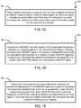
- FIG. 1B shows a diagram of an exemplary method 180 to examine visual field defects using the disclosed technology, e.g., such as including the system 100.
- the method 180 includes a process 182 to present, to a subject, visual stimuli in a plurality of sectors of a visual field of a subject, in which for each sector the presented visual stimuli includes an optical effect (e.g., light flickering) at a selected frequency.
- the method 180 includes a process 184 to acquire EEG signals from one or more electrodes in contact with the head of the subject.
- the method 180 includes a process 186 to data process (e.g., analyze) the acquired EEG signals to extract mfSSVEP data associated with the subject's EEG signal response to the presented visual stimuli.
- the method 180 includes a process 188 to produce a quantitative assessment of the visual field of the subject based on the MfSSVEP data.
- the quantitative assessment produced by the process 188 can provide an indication if there is a presence of a visual field defect in the user's visual field.
- the process 188 can include a process to determine the presence of the visual field defect in a sector having a mfSSVEP signal below a predetermined threshold.
- the visual stimuli presented by the process 182 can include multiple and repetitive optical effects flickering at the selected frequency in the corresponding sector of the visual field of the subject.
- the process 182 includes a process 181 to provide the visual stimuli to the visual display unit 112 (e.g., including a wearable visual display unit) from the data processing unit 120, in which the providing can include generating the visual stimuli (e.g., produce and/or assign an optical flickering effect of the visual stimuli at a selected frequency associated with each sector of the visual field); and/or supplying a previously generated visual stimuli.
- the visual display unit 112 e.g., including a wearable visual display unit
- the providing can include generating the visual stimuli (e.g., produce and/or assign an optical flickering effect of the visual stimuli at a selected frequency associated with each sector of the visual field); and/or supplying a previously generated visual stimuli.
- the process 181 to provide the visual stimuli includes forming a spatial visual stimulus display having multiple regions or sectors at different spatial locations, where for each region, the particular region includes an optical effect (e.g., light flickering) that changes at a unique frequency with respect to at least a proximate region or any other region of the visual stimulus display.
- an optical effect e.g., light flickering
- the process 188 can include a process 189 to analyze the mfSSVEP data with respect to a frequency spectrum including the designated frequencies mapped to the spatial regions of the visual stimulus display, in which the analyzing can include comparing the mfSSVEP signal at the particular frequencies to a predetermined threshold, or in relation to another mfSSVEP signal or other mfSSVEPs (e.g., including from an averaged population or individual group of mfSSVEP data with respect to that particular frequency), to determine if the signal falls below the predetermined threshold or is substantially lower with respect to a comparative mfSSVEP signal.
- the analyzing can include comparing the mfSSVEP signal at the particular frequencies to a predetermined threshold, or in relation to another mfSSVEP signal or other mfSSVEPs (e.g., including from an averaged population or individual group of mfSSVEP data with respect to that particular frequency), to determine if the signal falls below the predetermined threshold or is substantially lower with respect to a
- the method can include a process 190 to determine if the presence of a visual field defect based on the quantitative assessment, e.g., if the mfSSVEP signal for a particular frequency falls below the predetermined threshold or substantially lower than the comparative signal(s) from other mfSSVEP data at that particular frequency, in which the visual field deficiency is determined to be in the region of the visual stimulus display associated with the spatial location to which that frequency is mapped.
- a process 190 to determine if the presence of a visual field defect based on the quantitative assessment, e.g., if the mfSSVEP signal for a particular frequency falls below the predetermined threshold or substantially lower than the comparative signal(s) from other mfSSVEP data at that particular frequency, in which the visual field deficiency is determined to be in the region of the visual stimulus display associated with the spatial location to which that frequency is mapped.
- FIG. 1F shows diagrams depicting an exemplary implementation using multifocal steady-state visual-evoked potentials (mfSSVEP) for assessment of visual field defects.
- mfSSVEP multifocal steady-state visual-evoked potentials
- FIG. 2 shows images of an exemplary EEG setup used in exemplary implementations of the disclosed mfSSVEP visual field loss analysis techniques.
- the visual experiment was conducted inside a dark, soundproof shielded room. Visual stimuli were presented on a 19" CRT monitor in front of the participants at a distance of 50 cm with a refresh rate of 140 Hz and a resolution of 800 ⁇ 600 pixels.
- the modified 10-20 international system configuration of electrodes included 19 channels of electrodes arranged over parietal and occipital areas such as Pz, PO3, POz, PO4, O1, Oz, and O2.
- the EEG electrode configurations of the EEG unit 111 can include a single electrode placed on the head or neck of the patient, e.g., such as on head over the occipital region of the brain.
- the single electrode channel configuration can include 1 channel - Oz.
- the EEG electrode configuration of the EEG unit 111 can include 2 electrode channels (e.g., 2 channels - O1 and O2); or in other implementations, for example, as few as 3 channels (e.g., 3 channels - O1, O2 and Oz); or in other implementations, for example, as few as 4 channels (e.g., 4 channels - POz, O1, O2 and Oz); or or in other implementations, for example, as few as 8 channels (e.g., 8 channels - PO5, PO3, POz, PO4, PO6, O1, O2 and Oz).
- 2 electrode channels e.g., 2 channels - O1 and O2
- 3 channels e.g., 3 channels - O1, O2 and Oz
- 4 channels e.g., 4 channels - POz, O1, O2 and Oz
- 8 channels e.g., 8 channels - PO5, PO3, POz, PO4, PO6, O1, O2 and Oz.
- a layout of visual stimuli was designed to include 20 sectors in three concentric rings (e.g., subtending 6°, 15°, and 25° of the visual field). All sectors flickered concurrently at different frequencies ranging from 8 to 11.8 Hz with a frequency resolution of 0.2 Hz.
- a visual field loss (DEFICIT) condition was mimicked by replacing the 9 Hz sector (e.g., the 0-45° patch in the middle ring as shown in the diagram of FIG. 1F ) with a black patch, in contrast to the CONTROL condition in which all 20 sectors flickered concurrently.
- FIG. 3A shows data plots depicting the CONTROL-DEFICIT comparison for five participants, in which the exemplary red line of the plots represent the SSVEP frequency with the lowest signal-to-noise-ratio versus other frequencies (e.g., represented by the gray lines).
- FIG. 3B shows data plots depicting a BLOCK-CONTROL comparison in mfSSVEP profiles from a representative subject.
- the exemplary empirical results showed that four of five participants consistently exhibited a significant deterioration of the 9 Hz ssVEP amplitude in the DEFICIT condition, e.g., as compared to the CONTROL condition.
- the inconsistency from a participant (S3) was likely attributed to the absence of gaze-attentive fixation to the visual stimulus during the experiment, according to his self-report after the experiment.
- the disclosed technology includes a portable, objective mfSSVEP-based visual field assessment platform, e.g., which includes and integrates a wearable, wireless dry EEG system and a head-mounted display.
- the portable devices and systems can acquire and process measurements of reliable mfSSVEP signals that are quantitatively associated with visual field integrity of a subject.
- the exemplary platform can quantitate the integrity of monocular visual fields by the characterization of mfSSVEP signal data.
- the disclosed portable platform can allow assessment of visual field integrity in unconstrained situations and outside clinic environment.
- FIG. 4 shows an image of an exemplary portable EEG unit 111 of the disclosed portable, objective mfSSVEP-based visual field assessment platform.
- Exemplary characteristics of the exemplary EEG unit shown in FIG. 4 include easy-to-use and environment-free, which can avoid the burden of setting up laboratory EEG recording, enabling routine visual-field assessment or screening for visual field loss in non-clinic environments.
- Exemplary implementations using the exemplary portable devices and systems of the disclosed technology demonstrated that the strength of mfSSVEP signals is informative to serve as an objective indicator to reflect possible deficits in a monocular visual field.
- FIGS. 5A and 5B show exemplary wearable, wireless high-density EEG unit of the portable system platform.
- FIG. 5A shows a side view image
- FIG. 5B shows a back view image of an exemplary wearable, wireless 64-channel dry EEG unit.
- users of the exemplary portable system can easily put on the wearable EEG unit by themselves in their living environments.
- the exemplary portable system can in some embodiments employ a 64-channel high-density EEG, while in other embodiments can employ a reduced number of channels to provide an optimal configuration or montage for portably detecting mfSSVEP, e.g., outside of a non-office based environment.
- the exemplary portable system can employ advanced signal processing methods, e.g., such as spatial filtering and artifact removal, to improve signal-to-noise ratio of mfSSVEP from high-density recording.
- FIGS. 6A and 6B An exemplary head-mounted display unit of the portable system platform utilized an Oculus Rift goggle (Oculus VR, Inc.) to deliver the mfSSVEP stimulation, as depicted in FIGS. 6A and 6B.
- FIG. 6A shows an image of the exemplary head-mounted display unit to present the mfSSVEP stimulation
- FIG. 6B shows a diagram of the exemplary layout of the mfSSVEP stimulation presentation.
- the exemplary head-mounted display unit provides an inexpensive solution with a good image resolution of 1280 ⁇ 800, and also provides a whole-eye coverage allowing a controlled environment for visual-field assessment.
- the mobility can be obtained by communicatively connecting the exemplary head-mounted display unit to one or more mobile communication devices, e.g., such as a laptop as shown in the image of FIG. 6A , or other mobile devices.
- mobile communication devices e.g., such as a laptop as shown in the image of FIG. 6A
- tablets, smartphones, or wearable computing devices can also be communicatively connected to the exemplary head-mounted display unit.
- the same layout of the mfSSVEP stimulation was used as in other exemplary implementations, e.g., including 20 sectors in three rings (e.g., subtending 6°, 15°, and 25° of the visual field) flickering at frequencies from 8 to 11.8 Hz with a frequency resolution of 0.2 Hz were used (as shown in the diagram of FIG. 6B ).
- subjects can be tested under different experimental conditions, by varying testing parameters similarly to those previously described exemplary implementations.
- a visual field loss condition can be mimicked by using black patches to replace different sectors on the visual field and evaluate mfSSVEP signal loss compared to a control condition.
- the example portable system can be used for acquisition of mfSSVEP signals to obtain such data.
- exemplary techniques such as independent component analysis (ICA) and differential canonical correlation analysis can be implemented successfully for blind source separation and to enhance detectability of SSVEP signals.
- ICA independent component analysis
- differential canonical correlation analysis can be implemented successfully for blind source separation and to enhance detectability of SSVEP signals.
- Electrooculogram (EOG) methods of the disclosed technology can be utilized to successfully identify fixation losses and allow identification of unreliable mfSSVEP signals to be removed from further analyses.
- EEG Electrooculogram
- the strength of mfSSVEP in one of the five participates failed to accurately reflect the mimicked visual deficit, as depicted previously in FIG. 3A .
- the reason may be attributed to the absence of proper gaze fixation during the examination based on the patient's self-report.
- subjects need to remain fixating on the central target location during the testing. Due to the short duration of testing trials, this can be achieved in most subjects, yet, the disclosed technology includes a mechanism to identify and exclude unreliable EEG signals produced by fixation losses. This is especially relevant in portable testing that may be performed without supervision.
- the disclosed portable mfSSVEP systems can include an EOG unit.
- the EOG unit can include two or more dry and soft electrodes to be placed proximate the outer canthus of a subject's eyes (e.g., one or more electrodes per eye) to measure corneo-retinal standing potentials, and are in communication with a signal processing and wireless communication unit of the EOG unit to process the acquired signals from the electrodes and relay the processed signals as data to the data processing unit 120 of the portable system 100.
- the electrodes of the EOG unit can be in communication with the EEG unit 111 or visual display unit 112 to transfer the acquired signals from the outer canthus-placed electrodes of the EOG unit to the data processing unit 120.
- the disclosed techniques can concurrently monitor subjects' electrooculogram (EOG) signals to evaluate the gaze fixation.
- EOG electrooculogram
- the electric field changes associated with eye movements e.g., such as blinks and saccades, can be monitored.
- a calibration sequence can be used at the start of recording to determine the transformation equations.
- an EOG-guided mfSSVEP analysis can be implemented to automatically exclude the EEG segments where the subjects do not gaze at the center of the stimulation.
- four prefrontal electrodes can be switched to record the EOG signals, e.g., since mfSSVEP signals are presumably weak in the prefrontal regions.
- the EOG unit includes four electrodes, two electrodes can be placed below and above the right eye and another two will be placed at the left and right outer canthus.
- the EOG unit can be used to assess the accuracy of the portable mfSSVEP system by identifying potentially unreliable EEG signals induced by loss of fixation.
- the data processing unit 120 can process the acquired signals from the EOG unit electrodes with the EEG data acquired from the EEG unit 111 to identify unreliable signals, which can then be removed from the analysis of visual field integrity.
- the data processing unit 120 can execute analytical techniques to provide signal source separation.
- the disclosed portable mfSSVEP systems can include an eye tracking unit to monitor losses of fixation, e.g., and can further provide a reference standard.
- the eye tracking unit can be included, integrated, and/or incorporated into the visual display unit 112 (e.g., exemplary head-mounted display), for example.
- Exemplary implementations can be performed to evaluate the reproducibility of measurements obtained with the exemplary portable platform in evaluating its ability to detect visual field loss in patients with glaucoma compared to healthy control subjects.
- the disclosed portable systems can provide reproducible intra- and inter-visit mfSSVEP signals. mfSSVEP signals in patients with glaucomatous visual field loss will be significantly different than those in healthy control subjects.
- measurements obtained with portable systems need to be reproducible and be able to detect visual field losses in patients with glaucoma.
- Good reproducibility is a fundamental requirement in order to allow detection of change over time. If a test is to be used for screening, diagnosis, and/or detection of glaucoma progression, an initial step is demonstrating that a portable system is able to distinguish patients with glaucomatous field loss from healthy individuals.
- Exemplary implementations were conducted to demonstrate the reproducibility and diagnostic accuracy studies. Such implementations included participation of a group of 10 healthy and 10 glaucomatous subjects. These subjects had not been tested previously with the system. The subjects underwent five sessions of testing per visit for five different visits, spaced at intervals of approximately 1 week apart. Reproducibility measures were obtained, e.g., including coefficients of variation and intraclass correlation coefficients for the relevant measurements obtained by the portable system. For diagnostic accuracy evaluation, for example, tests of an additional sample of 20 healthy and 20 glaucomatous subjects were performed, e.g., totaling 30 subjects in each group. Glaucomatous subjects were shown to have repeatable abnormal visual field defects on SAP (SITA 24-2). For example, assessment of diagnostic accuracy was performed using receiver operating characteristic (ROC) curves. The sample size for this experiment provided 83% power to detect a minimum difference of 0.25 in ROC curve area compared to chance.
- ROC receiver operating characteristic
- Implementations of the subject matter and the functional operations described in this patent document can be implemented in various systems, digital electronic circuitry, or in computer software, firmware, or hardware, including the structures disclosed in this specification and their structural equivalents, or in combinations of one or more of them. Implementations of the subject matter described in this specification can be implemented as one or more computer program products, i.e., one or more modules of computer program instructions encoded on a tangible and non-transitory computer readable medium for execution by, or to control the operation of, data processing apparatus.
- the computer readable medium can be a machine-readable storage device, a machine-readable storage substrate, a memory device, a composition of matter effecting a machine-readable propagated signal, or a combination of one or more of them.
- data processing apparatus encompasses all apparatus, devices, and machines for processing data, including by way of example a programmable processor, a computer, or multiple processors or computers.
- the apparatus can include, in addition to hardware, code that creates an execution environment for the computer program in question, e.g., code that constitutes processor firmware, a protocol stack, a database management system, an operating system, or a combination of one or more of them.
- a computer program (also known as a program, software, software application, script, or code) can be written in any form of programming language, including compiled or interpreted languages, and it can be deployed in any form, including as a stand-alone program or as a module, component, subroutine, or other unit suitable for use in a computing environment.
- a computer program does not necessarily correspond to a file in a file system.
- a program can be stored in a portion of a file that holds other programs or data (e.g., one or more scripts stored in a markup language document), in a single file dedicated to the program in question, or in multiple coordinated files (e.g., files that store one or more modules, sub programs, or portions of code).
- a computer program can be deployed to be executed on one computer or on multiple computers that are located at one site or distributed across multiple sites and interconnected by a communication network.
- the processes and logic flows described in this specification can be performed by one or more programmable processors executing one or more computer programs to perform functions by operating on input data and generating output.
- the processes and logic flows can also be performed by, and apparatus can also be implemented as, special purpose logic circuitry, e.g., an FPGA (field programmable gate array) or an ASIC (application specific integrated circuit).
- processors suitable for the execution of a computer program include, by way of example, both general and special purpose microprocessors, and any one or more processors of any kind of digital computer.
- a processor will receive instructions and data from a read only memory or a random access memory or both.
- the essential elements of a computer are a processor for performing instructions and one or more memory devices for storing instructions and data.
- a computer will also include, or be operatively coupled to receive data from or transfer data to, or both, one or more mass storage devices for storing data, e.g., magnetic, magneto optical disks, or optical disks.
- mass storage devices for storing data, e.g., magnetic, magneto optical disks, or optical disks.
- a computer need not have such devices.
- Computer readable media suitable for storing computer program instructions and data include all forms of nonvolatile memory, media and memory devices, including by way of example semiconductor memory devices, e.g., EPROM, EEPROM, and flash memory devices.
- semiconductor memory devices e.g., EPROM, EEPROM, and flash memory devices.
- the processor and the memory can be supplemented by, or incorporated in, special purpose logic circuitry.
Landscapes
- Health & Medical Sciences (AREA)
- Life Sciences & Earth Sciences (AREA)
- Engineering & Computer Science (AREA)
- General Health & Medical Sciences (AREA)
- Veterinary Medicine (AREA)
- Biophysics (AREA)
- Biomedical Technology (AREA)
- Heart & Thoracic Surgery (AREA)
- Medical Informatics (AREA)
- Molecular Biology (AREA)
- Surgery (AREA)
- Animal Behavior & Ethology (AREA)
- Physics & Mathematics (AREA)
- Public Health (AREA)
- Pathology (AREA)
- Ophthalmology & Optometry (AREA)
- Psychiatry (AREA)
- Psychology (AREA)
- Educational Technology (AREA)
- Hospice & Palliative Care (AREA)
- Developmental Disabilities (AREA)
- Social Psychology (AREA)
- Child & Adolescent Psychology (AREA)
- Signal Processing (AREA)
- Human Computer Interaction (AREA)
- Multimedia (AREA)
- Measurement And Recording Of Electrical Phenomena And Electrical Characteristics Of The Living Body (AREA)
Claims (14)
- Tragbares Datenhelmsystem (100) zum Überwachen von Gehirnaktivität, die mit dem Sichtfeld eines Benutzers verknüpft ist, das Folgendes umfasst:ein Gehäuse, das auf dem Kopf des Benutzers tragbar ist;eine Sensoreinheit (111), die konfiguriert ist, um Elektroenzephalogramm(EEG)-Signale zu erfassen, einschließlich einer oder mehrerer Trockenelektroden, die an das Gehäuse angebracht sind, das auf dem Kopf eines Benutzers tragbar ist;eine visuelle Anzeigeeinheit (112), die einen Anzeigebildschirm einschließt, der konfiguriert ist, um dem Benutzer visuelle Reize in mehreren Sektoren eines Sichtfelds zu präsentieren, wobei die visuellen Reize mehrere Regionen einschließen, die in konzentrischen Ringen angeordnet sind, wobei jede der mehreren Regionen einen mehrfachen und sich wiederholenden optischen Flackereffekt gleichzeitig mit den anderen Regionen und bei einer ausgewählten Frequenz, die sich von der Flackerfrequenz der anderen Regionen unterscheidet, einschließt, wobei der optische Flackereffekt bei der ausgewählten Frequenz für die Region jedem Sektor des Sichtfelds zugeordnet wird, und wobei die visuellen Reize konfiguriert sind, um multifokale visuell evozierte Potentiale in einem stabilen Zustand (multifocal steady-state visual-evoked potentials - mfSSVEP) in den EEG-Signalen zu evozieren, die durch den Benutzer vorgewiesen werden, die durch die Sensoreinheit erfasst werden; undeine Datenverarbeitungseinheit (120), die für Folgendes konfiguriert ist:Erzeugen der visuellen Reize;Kommunizieren mit der Sensoreinheit und der visuellen Anzeigeeinheit;Analysieren der erfassten EEG-Signale; undErstellen einer Beurteilung des Sichtfelds des Benutzers, wobei die visuelle Anzeigeeinheit eine Abdeckung des gesamten Auges und ein kontrolliertes visuelles Umfeld für die Beurteilung bereitstellt.
- System nach Anspruch 1, wobei die erstellte Beurteilung des Sichtfelds des Benutzers eine quantitative Beurteilung ist, die angibt, ob ein Sichtfelddefekt in dem Sichtfeld des Benutzers vorhanden ist.
- System nach Anspruch 1, wobei die eine oder die mehreren Elektroden der Sensoreinheit Folgendes einschließen:
Trockenelektroden, die betriebsfähig sind, um die EEG-Signale ohne ein leitfähiges Gel, das in einer Schnittstelle zwischen den Elektroden und dem Benutzer liegt, zu erfassen, ein einzelner Elektrodenkanal Oz oder mehrere der Elektroden, die gemäß des internationalen 10-20-Systems an speziellen Stellen auf dem Kopf des Benutzers angeordnet sind. - System nach Anspruch 1, wobei das System tragbar ist, um es dem Benutzer zu ermöglichen, das System in dem Lebensumfeld des Benutzers und routinemäßig oder fortlaufend zu betreiben.
- System nach Anspruch 1, wobei die ausgewählte Frequenz des optischen Flackereffekts für eine spezielle Region bei einer unterschiedlichen Frequenz hinsichtlich des optischen Flackereffekts an einer nahen Region oder hinsichtlich der visuellen Flackereffekte in den anderen Regionen der visuellen Reize liegt.
- System nach Anspruch 5, wobei die visuellen Reize in 20 Regionen in drei konzentrischen Ringen präsentiert werden, einschließlich eines Abschneidens von 6°, 15° und 25° des Sichtfeldes.
- System nach Anspruch 5, wobei die ausgewählten Frequenzen des optischen Flackereffekts von jedem der mehreren Regionen der visuellen Reize über 6 Hz liegen.
- System nach Anspruch 1, das ferner Folgendes umfasst:
eine Elektrookulogramm(EOG)-Einheit einschließlich einer oder mehrerer Elektroden, die nahe des äußeren Kanthus jedes Auges des Benutzers zu platzieren sind, um korneoretinale Bestandspotential(corneo-retinal standing potential - CRSP)-Signale zu messen, wobei die eine oder die mehreren Elektroden der EOG-Einheit mit der Datenverarbeitungseinheit in Kommunikation stehen, um die erfassten CRSP-Signale von der einen oder den mehreren Elektroden zu verarbeiten, um Bewegungen der Augen des Benutzers zu bestimmen. - System nach Anspruch 1, wobei die visuelle Anzeigeeinheit (112) konfiguriert ist, um über den Augen des Benutzers tragbar zu sein, damit der Benutzer die präsentierten visuellen Reize auf dem Anzeigebildschirm sehen kann, und das System ferner Folgendes umfasst:
eine Blickbewegungsregistrierungsvorrichtung einschließlich einer Kamera, die in der tragbaren visuellen Anzeigeeinheit eingesetzt wird und in Kommunikation mit der Datenverarbeitungseinheit steht, wobei die Kamera betriebsfähig ist, um Bilder der Augen des Benutzers aufzuzeichnen. - Verfahren (180) zum Untersuchen eines Sichtfeldes eines Subjekts unter Verwendung eines Datenhelmsystems, wobei das Verfahren Folgendes umfasst:Erzeugen visueller Reize;Präsentieren (182), dem Subjekt in einem kontrollierten visuellen Umfeld, das die Abdeckung des gesamten Auges unter Verwendung einer visuellen Anzeigeeinheit bereitstellt, der visuellen Reize in mehreren Sektoren eines Sichtfeldes des Subjekts, wobei die visuellen Reize mehrere Regionen einschließen, die in konzentrischen Ringen angeordnet sind, wobei jede der mehreren Regionen einen mehrfachen, fortlaufenden und sich wiederholenden optischen Flackereffekt gleichzeitig mit den anderen Regionen und bei einer ausgewählten Frequenz, die sich von der Flackerfrequenz der anderen Regionen unterscheidet, einschließt, und wobei der optische Flackereffekt bei der ausgewählten Frequenz für die Region jedem Sektor des Sichtfelds zugeordnet wird;Erfassen (184) von Elektroenzephalogramm(EEG)-Signalen von einer oder mehreren Trockenelektroden, die in einer Sensoreinheit eingeschlossen sind, die auf dem Kopf des Subjekts tragbar ist und mit dem Kopf des Subjekts in Berührung ist;Verarbeiten (186) der erfassten EEG-Signale, um Daten multifokaler visuell evozierter Potentiale in einem stabilen Zustand (mfSSVEP) zu extrahieren, die mit der EEG-Signalantwort des Subjekts auf die präsentierten visuellen Reize verknüpft sind; undErstellen (188) einer quantitativen Beurteilung des Sichtfeldes des Subjekts basierend auf den MfSSVEP-Daten.
- Verfahren nach Anspruch 10, wobei die visuellen Reize in 20 Regionen in drei konzentrischen Ringen präsentiert werden, einschließlich des Abschneidens von 6°, 15° und 25° des Sichtfeldes.
- Verfahren nach Anspruch 10, wobei die eine oder die mehreren Elektroden einen einzelnen Elektrodenkanal Oz einschließen, der über der okzipitalen Region des Kopfes des Subjekts positioniert ist, wenn die Sensoreinheit von dem Subjekt getragen wird, oder die Elektroden Trockenelektroden einschließen, die betriebsfähig sind, um die EEG-Signale ohne leitfähiges Gel, das in einer Schnittstelle zwischen den Elektroden und dem Subjekt liegt, zu erfassen.
- Verfahren nach Anspruch 10, wobei das Überwachen der Bewegungen der Augen des Subjekts ein Verwenden einer Elektrookulogramm(EOG)-Einheit einschließt, einschließlich einer oder mehrerer Elektroden, die nahe des äußeren Kanthus jedes Auges des Subjekts platziert sind, um korneoretinale Bestandspotential(CRSP)-Signale zu messen.
- Verfahren nach Anspruch 10, das ferner Folgendes umfasst:
Ausbilden einer Anzeige für räumlichen visuellen Reiz, die die mehreren der Regionen an unterschiedlichen räumlichen Stellen auf der Anzeige für räumlichen visuellen Reiz aufweist, wobei, für jede Region, die Region den optischen Flackereffekt einschließt, der sich bei einer vorgesehenen Frequenz hinsichtlich wenigstens einer nahen Region oder der anderen Regionen der visuellen Reizanzeige ändert.
Applications Claiming Priority (2)
| Application Number | Priority Date | Filing Date | Title |
|---|---|---|---|
| US201461981145P | 2014-04-17 | 2014-04-17 | |
| PCT/US2015/026543 WO2015161300A1 (en) | 2014-04-17 | 2015-04-17 | Portable brian activity sensing platform for assessment of visual field deficits |
Publications (3)
| Publication Number | Publication Date |
|---|---|
| EP3131453A1 EP3131453A1 (de) | 2017-02-22 |
| EP3131453A4 EP3131453A4 (de) | 2017-12-20 |
| EP3131453B1 true EP3131453B1 (de) | 2021-01-20 |
Family
ID=54324645
Family Applications (1)
| Application Number | Title | Priority Date | Filing Date |
|---|---|---|---|
| EP15780001.2A Active EP3131453B1 (de) | 2014-04-17 | 2015-04-17 | Tragbare plattform zur messung der gehirnaktivität zur beurteilung von sichtfelddefiziten |
Country Status (6)
| Country | Link |
|---|---|
| US (2) | US20170035317A1 (de) |
| EP (1) | EP3131453B1 (de) |
| KR (1) | KR20160145131A (de) |
| CN (1) | CN106455968B (de) |
| CA (1) | CA2946301A1 (de) |
| WO (1) | WO2015161300A1 (de) |
Cited By (2)
| Publication number | Priority date | Publication date | Assignee | Title |
|---|---|---|---|---|
| DE102022201296A1 (de) | 2022-02-08 | 2023-08-10 | Carl Zeiss Meditec Ag | Anordnung zur Gewinnung diagnostischer Informationen vom Auge |
| US12178580B2 (en) | 2019-12-23 | 2024-12-31 | Alimetry Limited | Electrode patch and connection system |
Families Citing this family (62)
| Publication number | Priority date | Publication date | Assignee | Title |
|---|---|---|---|---|
| NZ773818A (en) | 2015-03-16 | 2022-07-29 | Magic Leap Inc | Methods and systems for diagnosing and treating health ailments |
| US9910275B2 (en) * | 2015-05-18 | 2018-03-06 | Samsung Electronics Co., Ltd. | Image processing for head mounted display devices |
| US11567028B2 (en) * | 2015-11-29 | 2023-01-31 | Ramot At Tel-Aviv University Ltd. | Sensing electrode and method of fabricating the same |
| WO2018057667A1 (en) * | 2016-09-20 | 2018-03-29 | Paradromics, Inc. | Systems and methods for detecting corrupt or inaccurate sensory representations |
| EP4026487A1 (de) * | 2016-10-26 | 2022-07-13 | Telefonaktiebolaget LM Ericsson (publ) | Identifizierung von sensorischen eingaben mit auswirkung auf die arbeitsspeicherlast eines individuums |
| WO2018085598A1 (en) * | 2016-11-02 | 2018-05-11 | Northeastern University | Portable brain and vision diagnostic and therapeutic system |
| JP2018079294A (ja) * | 2016-11-08 | 2018-05-24 | 群馬電機株式会社 | 運動支援装置 |
| WO2018105940A1 (ko) * | 2016-12-05 | 2018-06-14 | 고려대학교 산학협력단 | 인공 망막 시스템 |
| CN106859645A (zh) * | 2017-03-06 | 2017-06-20 | 广东工业大学 | 基于vr技术和ssvep的可穿戴设备及脑电采集系统 |
| EP3568739A4 (de) * | 2017-03-15 | 2020-03-11 | Samsung Electronics Co., Ltd. | Systeme und verfahren zur bestimmung von defekten im sichtfeld eines benutzers |
| US11179564B2 (en) | 2017-04-25 | 2021-11-23 | Washington University | Resorbable implant for stimulating tissue, systems including such implant, and methods of using |
| US20200060573A1 (en) * | 2017-05-02 | 2020-02-27 | HeadsafeIP Pty Ltd | Head mountable device |
| US12097037B2 (en) | 2017-06-20 | 2024-09-24 | The Trustees Of Columbia University In The City Of New York | System, method and computer-accessible medium for determining possibility/likelihood of mental disorder |
| CN107296586A (zh) * | 2017-06-20 | 2017-10-27 | 黄涌 | 视觉误差检测设备/方法及基于该设备的书写系统/方法 |
| EP3760115B1 (de) * | 2017-06-22 | 2026-01-14 | Oticon A/s | System zur erfassung elektrografischer signale |
| US11432757B2 (en) * | 2017-08-31 | 2022-09-06 | Zeto, Inc. | Method for hosting mobile access to high-resolution electroencephalography data |
| CN107898459B (zh) * | 2017-09-12 | 2025-06-06 | 深圳麦格米特电气股份有限公司 | 一种便携式视觉电生理检测系统 |
| EP3684463B1 (de) | 2017-09-19 | 2025-05-14 | Neuroenhancement Lab, LLC | Verfahren und vorrichtung für neuro-enhancement |
| EP3709861B1 (de) * | 2017-11-14 | 2024-06-05 | Vivid Vision, Inc. | Systeme zur sichtfeldanalyse |
| WO2019108968A1 (en) | 2017-12-01 | 2019-06-06 | Zeto, Inc. | Headset and electrodes for sensing bioelectrical potential and methods of operation thereof |
| US11717686B2 (en) | 2017-12-04 | 2023-08-08 | Neuroenhancement Lab, LLC | Method and apparatus for neuroenhancement to facilitate learning and performance |
| CN109938727A (zh) * | 2017-12-20 | 2019-06-28 | 中国科学院深圳先进技术研究院 | 非人灵长类动物三维视觉刺激实验系统和方法 |
| US12280219B2 (en) | 2017-12-31 | 2025-04-22 | NeuroLight, Inc. | Method and apparatus for neuroenhancement to enhance emotional response |
| US11478603B2 (en) | 2017-12-31 | 2022-10-25 | Neuroenhancement Lab, LLC | Method and apparatus for neuroenhancement to enhance emotional response |
| CN110063727A (zh) * | 2018-01-24 | 2019-07-30 | 苏州维视诺电子科技有限公司 | 一种判断用户视觉能力的方法和系统 |
| US11445972B2 (en) | 2018-04-09 | 2022-09-20 | Massachusetts Institute Of Technology | Brain-computer interface for user's visual focus detection |
| US11364361B2 (en) | 2018-04-20 | 2022-06-21 | Neuroenhancement Lab, LLC | System and method for inducing sleep by transplanting mental states |
| CN108958489A (zh) * | 2018-07-20 | 2018-12-07 | 东南大学 | 一种基于脑电和眼动仪的图像感兴趣区域快速检出方法 |
| CN113382683A (zh) | 2018-09-14 | 2021-09-10 | 纽罗因恒思蒙特实验有限责任公司 | 改善睡眠的系统和方法 |
| CN109717828A (zh) * | 2018-10-24 | 2019-05-07 | 中国医学科学院生物医学工程研究所 | 一种视野检查设备及检测方法 |
| CN109805923A (zh) * | 2019-01-29 | 2019-05-28 | 北京京东方光电科技有限公司 | 可穿戴设备、信号处理方法及装置 |
| CN109700428B (zh) * | 2019-02-28 | 2024-11-05 | 中国人民解放军第306医院 | 一种内置眼睛注视跟踪系统的角膜接触电极及工作方法 |
| TWI699672B (zh) * | 2019-03-25 | 2020-07-21 | 國家中山科學研究院 | 以腦波訊號辨識視覺控制指令之方法及裝置 |
| US11172869B2 (en) * | 2019-04-26 | 2021-11-16 | Hi Llc | Non-invasive system and method for product formulation assessment based on product-elicited brain state measurements |
| US11786694B2 (en) | 2019-05-24 | 2023-10-17 | NeuroLight, Inc. | Device, method, and app for facilitating sleep |
| CN110367981B (zh) * | 2019-07-10 | 2021-02-09 | 西安交通大学 | 一种弱视脑电客观定量检测装置 |
| CN110251065A (zh) * | 2019-07-17 | 2019-09-20 | 西安交通大学 | 基于运动视觉诱发电位的对比敏感度检测方法 |
| CN110464298B (zh) * | 2019-07-25 | 2021-11-02 | 深圳大学 | 一种脑电信号处理装置和方法 |
| CN110611793B (zh) * | 2019-08-30 | 2020-12-01 | 广州奇化有限公司 | 基于工业视觉的供应链信息采集与数据分析方法及装置 |
| WO2021099640A1 (en) * | 2019-11-21 | 2021-05-27 | Nextmind Sas | Human-machine interface device |
| CN114830069B (zh) * | 2019-12-18 | 2025-04-08 | 奈克斯特曼德公司 | 脑计算机接口 |
| EP4183379B1 (de) * | 2020-07-16 | 2025-12-24 | Nunaps Inc. | Bereitstellung von visuellem wahrnehmungstraining unter verwendung von visuellem wahrnehmungslernen |
| CN113018124A (zh) * | 2021-03-02 | 2021-06-25 | 常州市第一人民医院 | 一种用于单侧忽略患者的康复设备 |
| CN115390655A (zh) * | 2021-05-24 | 2022-11-25 | 华为技术有限公司 | 人机交互方法、人机交互装置及存储介质 |
| CN113552941A (zh) * | 2021-07-02 | 2021-10-26 | 上海厉鲨科技有限公司 | 多感官模态的bci-vr控制方法、系统及vr设备 |
| WO2023039572A1 (en) * | 2021-09-11 | 2023-03-16 | The Regents Of The University Of California | Simultaneous assessment of afferent and efferent visual pathways |
| CN114161414B (zh) * | 2021-12-03 | 2023-09-19 | 中国科学院沈阳自动化研究所 | 一种基于脑电和视觉的水下机械手控制系统及方法 |
| CN115227197A (zh) * | 2021-12-16 | 2022-10-25 | 河南省人民医院 | 一种用于视神经的检测系统 |
| CN114403898B (zh) * | 2022-01-24 | 2023-07-14 | 北京师范大学 | 一种脑电数据的噪声去除方法、装置及电子设备 |
| US20250032044A1 (en) * | 2022-03-30 | 2025-01-30 | University Of Pittsburgh-Of The Commonwealth System Of Higher Education | Eeg-guided spatial neglect detection system and detection method employing same |
| CN115024684B (zh) * | 2022-05-23 | 2024-11-22 | 天津大学 | 刺激范式生成系统、脑-机接口系统、检测方法及装置 |
| GB2637874A (en) * | 2022-08-12 | 2025-08-06 | Mindportal Inc | Systems and methods that involve BCI (Brain Computer Interface) and/or process saliency maps, eye tracking information and/or various controls or instructions |
| CN115120240B (zh) * | 2022-08-30 | 2022-12-02 | 山东心法科技有限公司 | 特殊行业目标感知技能的敏感性评估方法、设备及介质 |
| CN115714832A (zh) * | 2022-10-24 | 2023-02-24 | 南京航空航天大学 | 一种基于稳态视觉诱发电位的电话拨打系统的操作方法 |
| CN115935271A (zh) * | 2022-12-16 | 2023-04-07 | 北京理工大学 | 基于多频空间混合编码的脑图谱诱发和分类方法及系统 |
| CN116058784A (zh) * | 2022-12-16 | 2023-05-05 | 清华大学 | 视功能检测系统、方法、装置、计算机设备和存储介质 |
| WO2024142111A1 (en) * | 2022-12-28 | 2024-07-04 | Khosla Shaurya | A device for tracking user eye and head position |
| US12303273B2 (en) * | 2023-03-17 | 2025-05-20 | SB Technology, Inc. | Signal processing methods and systems for biomagnetic field imaging |
| WO2025022510A1 (ja) * | 2023-07-22 | 2025-01-30 | 株式会社仙台放送 | 情報処理システム、情報処理方法、表示装置およびコンピュータプログラム |
| WO2025122906A1 (en) * | 2023-12-07 | 2025-06-12 | Dandelion Science Corp. | Method and system for tagging visual features in video material and neuroimaging recovery of visual evoked potentials |
| WO2025216156A1 (ja) * | 2024-04-12 | 2025-10-16 | 株式会社村田製作所 | 視野範囲判定装置、視野範囲判定方法 |
| CN119597148B (zh) * | 2024-11-18 | 2025-12-09 | 中国农业银行股份有限公司 | 一种基于混合脑机接口的银行系统交互方法及装置 |
Family Cites Families (17)
| Publication number | Priority date | Publication date | Assignee | Title |
|---|---|---|---|---|
| US4561448A (en) * | 1984-02-02 | 1985-12-31 | Colen-Kery, Inc. | Apparatus for sensing and recording biopotential electrical signals |
| US5035500A (en) * | 1988-08-12 | 1991-07-30 | Rorabaugh Dale A | Automated ocular perimetry, particularly kinetic perimetry |
| WO2000057772A1 (en) * | 1999-03-31 | 2000-10-05 | Virtual-Eye.Com, Inc. | Kinetic visual field apparatus and method |
| US7740592B2 (en) * | 2000-04-17 | 2010-06-22 | The University Of Sydney | Method and apparatus for objective electrophysiological assessment of visual function |
| US7578795B2 (en) * | 2001-08-07 | 2009-08-25 | Diopsys, Inc. | System and method for vision examination utilizing fault detection |
| US7753524B2 (en) * | 2002-02-08 | 2010-07-13 | Novavision, Inc. | Process and device for treating blind regions of the visual field |
| EP1928295A2 (de) * | 2005-09-02 | 2008-06-11 | EL-Vision Ltd. | Multifunktionales optometrisches-ophthalmisches system zur untersuchung, diagnose oder behandlung der sehkraft oder augen einer person und methoden dafür |
| DK2139390T3 (da) * | 2006-12-22 | 2017-11-27 | Neuro-Insight Pty Ltd | Fremgangsmåde til evaluering af effektiviteten af kommerciel kommunikation |
| US20080177352A1 (en) * | 2007-01-22 | 2008-07-24 | Novavision, Inc. | Device for Treating Human Vision Using Combined Optical and Electrical Stimulation |
| US20090062680A1 (en) * | 2007-09-04 | 2009-03-05 | Brain Train | Artifact detection and correction system for electroencephalograph neurofeedback training methodology |
| US8083354B2 (en) * | 2007-10-03 | 2011-12-27 | Diopsys, Inc. | Simultaneously multi-temporal visual test and method and apparatus therefor |
| US8838226B2 (en) * | 2009-12-01 | 2014-09-16 | Neuro Wave Systems Inc | Multi-channel brain or cortical activity monitoring and method |
| CN201926979U (zh) * | 2010-12-16 | 2011-08-10 | 刘国忠 | 一种脑机接口设备 |
| EP2755547A4 (de) * | 2011-09-16 | 2015-04-01 | Annidis Corp | System und verfahren zur beurteilung der netzhautfunktion |
| US8812097B2 (en) * | 2012-02-06 | 2014-08-19 | Honeywell International Inc. | Neurologically based non-invasive blood glucose concentration system and method |
| WO2015126987A1 (en) * | 2014-02-18 | 2015-08-27 | Merge Labs, Inc. | Head mounted display goggles for use with mobile computing devices |
| KR102491130B1 (ko) * | 2016-06-20 | 2023-01-19 | 매직 립, 인코포레이티드 | 시각적 프로세싱 및 지각 상태들을 포함하는 신경학적 상태들의 평가 및 수정을 위한 증강 현실 디스플레이 시스템 |
-
2015
- 2015-04-17 KR KR1020167031738A patent/KR20160145131A/ko not_active Withdrawn
- 2015-04-17 WO PCT/US2015/026543 patent/WO2015161300A1/en not_active Ceased
- 2015-04-17 CN CN201580030650.3A patent/CN106455968B/zh active Active
- 2015-04-17 CA CA2946301A patent/CA2946301A1/en not_active Abandoned
- 2015-04-17 US US15/304,803 patent/US20170035317A1/en not_active Abandoned
- 2015-04-17 EP EP15780001.2A patent/EP3131453B1/de active Active
-
2020
- 2020-11-09 US US17/093,575 patent/US20210052182A1/en not_active Abandoned
Non-Patent Citations (1)
| Title |
|---|
| None * |
Cited By (4)
| Publication number | Priority date | Publication date | Assignee | Title |
|---|---|---|---|---|
| US12178580B2 (en) | 2019-12-23 | 2024-12-31 | Alimetry Limited | Electrode patch and connection system |
| US12245862B2 (en) | 2019-12-23 | 2025-03-11 | Alimetry Limited | Electrode patch and connection system |
| DE102022201296A1 (de) | 2022-02-08 | 2023-08-10 | Carl Zeiss Meditec Ag | Anordnung zur Gewinnung diagnostischer Informationen vom Auge |
| WO2023152121A1 (de) | 2022-02-08 | 2023-08-17 | Carl Zeiss Meditec Ag | Anordnung zur gewinnung diagnostischer informationen vom auge |
Also Published As
| Publication number | Publication date |
|---|---|
| CA2946301A1 (en) | 2015-10-22 |
| US20210052182A1 (en) | 2021-02-25 |
| CN106455968A (zh) | 2017-02-22 |
| US20170035317A1 (en) | 2017-02-09 |
| KR20160145131A (ko) | 2016-12-19 |
| EP3131453A4 (de) | 2017-12-20 |
| WO2015161300A1 (en) | 2015-10-22 |
| CN106455968B (zh) | 2021-08-17 |
| EP3131453A1 (de) | 2017-02-22 |
Similar Documents
| Publication | Publication Date | Title |
|---|---|---|
| US20210052182A1 (en) | Portable brain activity sensing platform for assessment of visual field deficits | |
| US20240188879A1 (en) | System and method for detecting neurological disease | |
| US10258291B2 (en) | Systems and methods for evaluation of neuropathologies | |
| CA2701544C (en) | Simultaneously multi-temporal visual test and method and apparatus therefor | |
| EP2906115B1 (de) | Konfiguration und räumliche platzierung frontaler elektrodensensoren zur erkennung physiologischer signale | |
| US20200060573A1 (en) | Head mountable device | |
| CN107296586A (zh) | 视觉误差检测设备/方法及基于该设备的书写系统/方法 | |
| JP2004537360A (ja) | 視覚検査のシステムおよび方法 | |
| US10888241B2 (en) | Device and method to determine objectively visual memory of images | |
| CN112842360A (zh) | 一种判断优势眼和非优势眼的方法及系统 | |
| Lascano et al. | Increasing the diagnostic value of evoked potentials in multiple sclerosis by quantitative topographic analysis of multichannel recordings | |
| CN117936066A (zh) | 一种基于视觉Oddball范式的iNPH预测方法 | |
| RU2852060C1 (ru) | Способ нейрофизиологической диагностики нарушений обработки информации, связанной с восприятием лицевой экспрессии у пациентов с шизофренией и шизоаффективным расстройством | |
| US20250134447A1 (en) | Simultaneous assessement of afferent and efferent visual pathways | |
| US20250082252A1 (en) | Inph prediction method and device based on the new/old stimulus bci paradigm | |
| Xu et al. | Evaluation of Steady-State Visual Evoked Potentials (SSVEP) Stimuli Design for Visual Field Assessment | |
| Fukuda et al. | Design and validation of a novel portable electrode holder for motor-related EEG measurement | |
| Zębrowski et al. | A large-scale investigation of the resting-state alpha-band activity in relation to interindividual differences in visual perception | |
| Schadow et al. | Gestalt perception in hemianopic patients: performance measures and VEPs |
Legal Events
| Date | Code | Title | Description |
|---|---|---|---|
| STAA | Information on the status of an ep patent application or granted ep patent |
Free format text: STATUS: THE INTERNATIONAL PUBLICATION HAS BEEN MADE |
|
| PUAI | Public reference made under article 153(3) epc to a published international application that has entered the european phase |
Free format text: ORIGINAL CODE: 0009012 |
|
| STAA | Information on the status of an ep patent application or granted ep patent |
Free format text: STATUS: REQUEST FOR EXAMINATION WAS MADE |
|
| 17P | Request for examination filed |
Effective date: 20161114 |
|
| AK | Designated contracting states |
Kind code of ref document: A1 Designated state(s): AL AT BE BG CH CY CZ DE DK EE ES FI FR GB GR HR HU IE IS IT LI LT LU LV MC MK MT NL NO PL PT RO RS SE SI SK SM TR |
|
| AX | Request for extension of the european patent |
Extension state: BA ME |
|
| DAV | Request for validation of the european patent (deleted) | ||
| DAX | Request for extension of the european patent (deleted) | ||
| A4 | Supplementary search report drawn up and despatched |
Effective date: 20171117 |
|
| RIC1 | Information provided on ipc code assigned before grant |
Ipc: A61B 5/00 20060101ALI20171113BHEP Ipc: A61B 3/024 20060101AFI20171113BHEP Ipc: A61B 5/0496 20060101ALI20171113BHEP Ipc: A61B 5/0484 20060101ALI20171113BHEP Ipc: A61B 5/0478 20060101ALI20171113BHEP Ipc: A61B 5/16 20060101ALI20171113BHEP Ipc: A61B 5/04 20060101ALI20171113BHEP |
|
| STAA | Information on the status of an ep patent application or granted ep patent |
Free format text: STATUS: EXAMINATION IS IN PROGRESS |
|
| 17Q | First examination report despatched |
Effective date: 20181004 |
|
| GRAP | Despatch of communication of intention to grant a patent |
Free format text: ORIGINAL CODE: EPIDOSNIGR1 |
|
| STAA | Information on the status of an ep patent application or granted ep patent |
Free format text: STATUS: GRANT OF PATENT IS INTENDED |
|
| INTG | Intention to grant announced |
Effective date: 20200731 |
|
| GRAS | Grant fee paid |
Free format text: ORIGINAL CODE: EPIDOSNIGR3 |
|
| GRAA | (expected) grant |
Free format text: ORIGINAL CODE: 0009210 |
|
| STAA | Information on the status of an ep patent application or granted ep patent |
Free format text: STATUS: THE PATENT HAS BEEN GRANTED |
|
| AK | Designated contracting states |
Kind code of ref document: B1 Designated state(s): AL AT BE BG CH CY CZ DE DK EE ES FI FR GB GR HR HU IE IS IT LI LT LU LV MC MK MT NL NO PL PT RO RS SE SI SK SM TR |
|
| REG | Reference to a national code |
Ref country code: GB Ref legal event code: FG4D |
|
| REG | Reference to a national code |
Ref country code: CH Ref legal event code: EP |
|
| REG | Reference to a national code |
Ref country code: DE Ref legal event code: R096 Ref document number: 602015064981 Country of ref document: DE |
|
| REG | Reference to a national code |
Ref country code: AT Ref legal event code: REF Ref document number: 1355620 Country of ref document: AT Kind code of ref document: T Effective date: 20210215 |
|
| REG | Reference to a national code |
Ref country code: IE Ref legal event code: FG4D |
|
| REG | Reference to a national code |
Ref country code: NL Ref legal event code: MP Effective date: 20210120 |
|
| REG | Reference to a national code |
Ref country code: LT Ref legal event code: MG9D |
|
| REG | Reference to a national code |
Ref country code: AT Ref legal event code: MK05 Ref document number: 1355620 Country of ref document: AT Kind code of ref document: T Effective date: 20210120 |
|
| PG25 | Lapsed in a contracting state [announced via postgrant information from national office to epo] |
Ref country code: PT Free format text: LAPSE BECAUSE OF FAILURE TO SUBMIT A TRANSLATION OF THE DESCRIPTION OR TO PAY THE FEE WITHIN THE PRESCRIBED TIME-LIMIT Effective date: 20210520 Ref country code: LT Free format text: LAPSE BECAUSE OF FAILURE TO SUBMIT A TRANSLATION OF THE DESCRIPTION OR TO PAY THE FEE WITHIN THE PRESCRIBED TIME-LIMIT Effective date: 20210120 Ref country code: NO Free format text: LAPSE BECAUSE OF FAILURE TO SUBMIT A TRANSLATION OF THE DESCRIPTION OR TO PAY THE FEE WITHIN THE PRESCRIBED TIME-LIMIT Effective date: 20210420 Ref country code: NL Free format text: LAPSE BECAUSE OF FAILURE TO SUBMIT A TRANSLATION OF THE DESCRIPTION OR TO PAY THE FEE WITHIN THE PRESCRIBED TIME-LIMIT Effective date: 20210120 Ref country code: BG Free format text: LAPSE BECAUSE OF FAILURE TO SUBMIT A TRANSLATION OF THE DESCRIPTION OR TO PAY THE FEE WITHIN THE PRESCRIBED TIME-LIMIT Effective date: 20210420 Ref country code: HR Free format text: LAPSE BECAUSE OF FAILURE TO SUBMIT A TRANSLATION OF THE DESCRIPTION OR TO PAY THE FEE WITHIN THE PRESCRIBED TIME-LIMIT Effective date: 20210120 Ref country code: FI Free format text: LAPSE BECAUSE OF FAILURE TO SUBMIT A TRANSLATION OF THE DESCRIPTION OR TO PAY THE FEE WITHIN THE PRESCRIBED TIME-LIMIT Effective date: 20210120 Ref country code: GR Free format text: LAPSE BECAUSE OF FAILURE TO SUBMIT A TRANSLATION OF THE DESCRIPTION OR TO PAY THE FEE WITHIN THE PRESCRIBED TIME-LIMIT Effective date: 20210421 |
|
| PG25 | Lapsed in a contracting state [announced via postgrant information from national office to epo] |
Ref country code: SE Free format text: LAPSE BECAUSE OF FAILURE TO SUBMIT A TRANSLATION OF THE DESCRIPTION OR TO PAY THE FEE WITHIN THE PRESCRIBED TIME-LIMIT Effective date: 20210120 Ref country code: RS Free format text: LAPSE BECAUSE OF FAILURE TO SUBMIT A TRANSLATION OF THE DESCRIPTION OR TO PAY THE FEE WITHIN THE PRESCRIBED TIME-LIMIT Effective date: 20210120 Ref country code: LV Free format text: LAPSE BECAUSE OF FAILURE TO SUBMIT A TRANSLATION OF THE DESCRIPTION OR TO PAY THE FEE WITHIN THE PRESCRIBED TIME-LIMIT Effective date: 20210120 Ref country code: PL Free format text: LAPSE BECAUSE OF FAILURE TO SUBMIT A TRANSLATION OF THE DESCRIPTION OR TO PAY THE FEE WITHIN THE PRESCRIBED TIME-LIMIT Effective date: 20210120 Ref country code: AT Free format text: LAPSE BECAUSE OF FAILURE TO SUBMIT A TRANSLATION OF THE DESCRIPTION OR TO PAY THE FEE WITHIN THE PRESCRIBED TIME-LIMIT Effective date: 20210120 |
|
| PG25 | Lapsed in a contracting state [announced via postgrant information from national office to epo] |
Ref country code: IS Free format text: LAPSE BECAUSE OF FAILURE TO SUBMIT A TRANSLATION OF THE DESCRIPTION OR TO PAY THE FEE WITHIN THE PRESCRIBED TIME-LIMIT Effective date: 20210520 |
|
| REG | Reference to a national code |
Ref country code: DE Ref legal event code: R097 Ref document number: 602015064981 Country of ref document: DE |
|
| PG25 | Lapsed in a contracting state [announced via postgrant information from national office to epo] |
Ref country code: EE Free format text: LAPSE BECAUSE OF FAILURE TO SUBMIT A TRANSLATION OF THE DESCRIPTION OR TO PAY THE FEE WITHIN THE PRESCRIBED TIME-LIMIT Effective date: 20210120 Ref country code: CZ Free format text: LAPSE BECAUSE OF FAILURE TO SUBMIT A TRANSLATION OF THE DESCRIPTION OR TO PAY THE FEE WITHIN THE PRESCRIBED TIME-LIMIT Effective date: 20210120 Ref country code: SM Free format text: LAPSE BECAUSE OF FAILURE TO SUBMIT A TRANSLATION OF THE DESCRIPTION OR TO PAY THE FEE WITHIN THE PRESCRIBED TIME-LIMIT Effective date: 20210120 |
|
| PLBE | No opposition filed within time limit |
Free format text: ORIGINAL CODE: 0009261 |
|
| STAA | Information on the status of an ep patent application or granted ep patent |
Free format text: STATUS: NO OPPOSITION FILED WITHIN TIME LIMIT |
|
| PG25 | Lapsed in a contracting state [announced via postgrant information from national office to epo] |
Ref country code: SK Free format text: LAPSE BECAUSE OF FAILURE TO SUBMIT A TRANSLATION OF THE DESCRIPTION OR TO PAY THE FEE WITHIN THE PRESCRIBED TIME-LIMIT Effective date: 20210120 Ref country code: RO Free format text: LAPSE BECAUSE OF FAILURE TO SUBMIT A TRANSLATION OF THE DESCRIPTION OR TO PAY THE FEE WITHIN THE PRESCRIBED TIME-LIMIT Effective date: 20210120 Ref country code: MC Free format text: LAPSE BECAUSE OF FAILURE TO SUBMIT A TRANSLATION OF THE DESCRIPTION OR TO PAY THE FEE WITHIN THE PRESCRIBED TIME-LIMIT Effective date: 20210120 Ref country code: ES Free format text: LAPSE BECAUSE OF FAILURE TO SUBMIT A TRANSLATION OF THE DESCRIPTION OR TO PAY THE FEE WITHIN THE PRESCRIBED TIME-LIMIT Effective date: 20210120 Ref country code: DK Free format text: LAPSE BECAUSE OF FAILURE TO SUBMIT A TRANSLATION OF THE DESCRIPTION OR TO PAY THE FEE WITHIN THE PRESCRIBED TIME-LIMIT Effective date: 20210120 |
|
| 26N | No opposition filed |
Effective date: 20211021 |
|
| PG25 | Lapsed in a contracting state [announced via postgrant information from national office to epo] |
Ref country code: LU Free format text: LAPSE BECAUSE OF NON-PAYMENT OF DUE FEES Effective date: 20210417 |
|
| REG | Reference to a national code |
Ref country code: BE Ref legal event code: MM Effective date: 20210430 |
|
| PG25 | Lapsed in a contracting state [announced via postgrant information from national office to epo] |
Ref country code: CH Free format text: LAPSE BECAUSE OF NON-PAYMENT OF DUE FEES Effective date: 20210430 Ref country code: AL Free format text: LAPSE BECAUSE OF FAILURE TO SUBMIT A TRANSLATION OF THE DESCRIPTION OR TO PAY THE FEE WITHIN THE PRESCRIBED TIME-LIMIT Effective date: 20210120 Ref country code: LI Free format text: LAPSE BECAUSE OF NON-PAYMENT OF DUE FEES Effective date: 20210430 |
|
| PG25 | Lapsed in a contracting state [announced via postgrant information from national office to epo] |
Ref country code: SI Free format text: LAPSE BECAUSE OF FAILURE TO SUBMIT A TRANSLATION OF THE DESCRIPTION OR TO PAY THE FEE WITHIN THE PRESCRIBED TIME-LIMIT Effective date: 20210120 |
|
| PG25 | Lapsed in a contracting state [announced via postgrant information from national office to epo] |
Ref country code: IT Free format text: LAPSE BECAUSE OF FAILURE TO SUBMIT A TRANSLATION OF THE DESCRIPTION OR TO PAY THE FEE WITHIN THE PRESCRIBED TIME-LIMIT Effective date: 20210120 Ref country code: IE Free format text: LAPSE BECAUSE OF NON-PAYMENT OF DUE FEES Effective date: 20210417 |
|
| REG | Reference to a national code |
Ref country code: DE Ref legal event code: R082 Ref document number: 602015064981 Country of ref document: DE Representative=s name: SIMMONS & SIMMONS LLP, DE |
|
| PG25 | Lapsed in a contracting state [announced via postgrant information from national office to epo] |
Ref country code: IS Free format text: LAPSE BECAUSE OF FAILURE TO SUBMIT A TRANSLATION OF THE DESCRIPTION OR TO PAY THE FEE WITHIN THE PRESCRIBED TIME-LIMIT Effective date: 20210520 |
|
| PG25 | Lapsed in a contracting state [announced via postgrant information from national office to epo] |
Ref country code: BE Free format text: LAPSE BECAUSE OF NON-PAYMENT OF DUE FEES Effective date: 20210430 |
|
| PG25 | Lapsed in a contracting state [announced via postgrant information from national office to epo] |
Ref country code: HU Free format text: LAPSE BECAUSE OF FAILURE TO SUBMIT A TRANSLATION OF THE DESCRIPTION OR TO PAY THE FEE WITHIN THE PRESCRIBED TIME-LIMIT; INVALID AB INITIO Effective date: 20150417 |
|
| PG25 | Lapsed in a contracting state [announced via postgrant information from national office to epo] |
Ref country code: CY Free format text: LAPSE BECAUSE OF FAILURE TO SUBMIT A TRANSLATION OF THE DESCRIPTION OR TO PAY THE FEE WITHIN THE PRESCRIBED TIME-LIMIT Effective date: 20210120 |
|
| PG25 | Lapsed in a contracting state [announced via postgrant information from national office to epo] |
Ref country code: MK Free format text: LAPSE BECAUSE OF FAILURE TO SUBMIT A TRANSLATION OF THE DESCRIPTION OR TO PAY THE FEE WITHIN THE PRESCRIBED TIME-LIMIT Effective date: 20210120 |
|
| PG25 | Lapsed in a contracting state [announced via postgrant information from national office to epo] |
Ref country code: TR Free format text: LAPSE BECAUSE OF FAILURE TO SUBMIT A TRANSLATION OF THE DESCRIPTION OR TO PAY THE FEE WITHIN THE PRESCRIBED TIME-LIMIT Effective date: 20210120 |
|
| PG25 | Lapsed in a contracting state [announced via postgrant information from national office to epo] |
Ref country code: MT Free format text: LAPSE BECAUSE OF FAILURE TO SUBMIT A TRANSLATION OF THE DESCRIPTION OR TO PAY THE FEE WITHIN THE PRESCRIBED TIME-LIMIT Effective date: 20210120 |
|
| PGFP | Annual fee paid to national office [announced via postgrant information from national office to epo] |
Ref country code: DE Payment date: 20250429 Year of fee payment: 11 |
|
| PGFP | Annual fee paid to national office [announced via postgrant information from national office to epo] |
Ref country code: FR Payment date: 20250425 Year of fee payment: 11 |
|
| PGFP | Annual fee paid to national office [announced via postgrant information from national office to epo] |
Ref country code: GB Payment date: 20260326 Year of fee payment: 12 |