EP3131685B1 - Dispositif de distribution d'un matériau - Google Patents
Dispositif de distribution d'un matériau Download PDFInfo
- Publication number
- EP3131685B1 EP3131685B1 EP15708097.9A EP15708097A EP3131685B1 EP 3131685 B1 EP3131685 B1 EP 3131685B1 EP 15708097 A EP15708097 A EP 15708097A EP 3131685 B1 EP3131685 B1 EP 3131685B1
- Authority
- EP
- European Patent Office
- Prior art keywords
- spindle
- piston
- container
- section
- axial position
- Prior art date
- Legal status (The legal status is an assumption and is not a legal conclusion. Google has not performed a legal analysis and makes no representation as to the accuracy of the status listed.)
- Active
Links
Images

Classifications
-
- B—PERFORMING OPERATIONS; TRANSPORTING
- B05—SPRAYING OR ATOMISING IN GENERAL; APPLYING FLUENT MATERIALS TO SURFACES, IN GENERAL
- B05C—APPARATUS FOR APPLYING FLUENT MATERIALS TO SURFACES, IN GENERAL
- B05C17/00—Hand tools or apparatus using hand held tools, for applying liquids or other fluent materials to, for spreading applied liquids or other fluent materials on, or for partially removing applied liquids or other fluent materials from, surfaces
- B05C17/005—Hand tools or apparatus using hand held tools, for applying liquids or other fluent materials to, for spreading applied liquids or other fluent materials on, or for partially removing applied liquids or other fluent materials from, surfaces for discharging material from a reservoir or container located in or on the hand tool through an outlet orifice by pressure without using surface contacting members like pads or brushes
- B05C17/00576—Hand tools or apparatus using hand held tools, for applying liquids or other fluent materials to, for spreading applied liquids or other fluent materials on, or for partially removing applied liquids or other fluent materials from, surfaces for discharging material from a reservoir or container located in or on the hand tool through an outlet orifice by pressure without using surface contacting members like pads or brushes characterised by the construction of a piston as pressure exerting means, or of the co-operating container
-
- A—HUMAN NECESSITIES
- A61—MEDICAL OR VETERINARY SCIENCE; HYGIENE
- A61C—DENTISTRY; APPARATUS OR METHODS FOR ORAL OR DENTAL HYGIENE
- A61C5/00—Filling or capping teeth
- A61C5/60—Devices specially adapted for pressing or mixing capping or filling materials, e.g. amalgam presses
- A61C5/62—Applicators, e.g. syringes or guns
-
- B—PERFORMING OPERATIONS; TRANSPORTING
- B05—SPRAYING OR ATOMISING IN GENERAL; APPLYING FLUENT MATERIALS TO SURFACES, IN GENERAL
- B05C—APPARATUS FOR APPLYING FLUENT MATERIALS TO SURFACES, IN GENERAL
- B05C17/00—Hand tools or apparatus using hand held tools, for applying liquids or other fluent materials to, for spreading applied liquids or other fluent materials on, or for partially removing applied liquids or other fluent materials from, surfaces
- B05C17/005—Hand tools or apparatus using hand held tools, for applying liquids or other fluent materials to, for spreading applied liquids or other fluent materials on, or for partially removing applied liquids or other fluent materials from, surfaces for discharging material from a reservoir or container located in or on the hand tool through an outlet orifice by pressure without using surface contacting members like pads or brushes
- B05C17/00593—Hand tools of the syringe type
-
- B—PERFORMING OPERATIONS; TRANSPORTING
- B05—SPRAYING OR ATOMISING IN GENERAL; APPLYING FLUENT MATERIALS TO SURFACES, IN GENERAL
- B05C—APPARATUS FOR APPLYING FLUENT MATERIALS TO SURFACES, IN GENERAL
- B05C17/00—Hand tools or apparatus using hand held tools, for applying liquids or other fluent materials to, for spreading applied liquids or other fluent materials on, or for partially removing applied liquids or other fluent materials from, surfaces
- B05C17/005—Hand tools or apparatus using hand held tools, for applying liquids or other fluent materials to, for spreading applied liquids or other fluent materials on, or for partially removing applied liquids or other fluent materials from, surfaces for discharging material from a reservoir or container located in or on the hand tool through an outlet orifice by pressure without using surface contacting members like pads or brushes
- B05C17/01—Hand tools or apparatus using hand held tools, for applying liquids or other fluent materials to, for spreading applied liquids or other fluent materials on, or for partially removing applied liquids or other fluent materials from, surfaces for discharging material from a reservoir or container located in or on the hand tool through an outlet orifice by pressure without using surface contacting members like pads or brushes with manually mechanically or electrically actuated piston or the like
- B05C17/0116—Hand tools or apparatus using hand held tools, for applying liquids or other fluent materials to, for spreading applied liquids or other fluent materials on, or for partially removing applied liquids or other fluent materials from, surfaces for discharging material from a reservoir or container located in or on the hand tool through an outlet orifice by pressure without using surface contacting members like pads or brushes with manually mechanically or electrically actuated piston or the like characterised by the piston driving means
- B05C17/0133—Nut and bolt advancing mechanism, e.g. threaded piston rods
Definitions
- the invention relates to a device for dispensing a material, and in particular to a device having a piston and a spindle which in one operation mode of the device are rotatable relative to each other so that rotating the spindle does not necessarily rotate the piston, and which in a further operation mode of the device the spindle and the piston are anti-twist locked with each other so that rotating the spindle also causes the piston to rotate.
- WO 2006/108085 A2 discloses a syringe delivery system for dispensing a highly viscous material through a syringe delivery opening.
- the system includes a syringe barrel having a delivery opening, a plunger including a threaded shaft that threadably engages the syringe barrel for selectively dispensing a viscous material through the delivery opening, and a plunger gripping member in gripping communication with the plunger that includes means for sealing the threaded shaft of the plunger so as to prevent contamination by foreign matter.
- the invention relates to a device for dispensing a material, preferably a dental material as defined in independent claims 1 and 8.
- the device comprises a container for holding or storing the material.
- the device further comprises a piston movably arranged within the container and a spindle in cooperation with the piston.
- the device is configured such that the spindle and the container are rotatable about a rotation axis relative to each other to (axially) move the piston for dispensing the material.
- the piston and the spindle are adapted to anti-twist lock against each other in a first axial position of the piston relative to spindle, whereas in a second axial position of the piston relative to spindle the anti-twist lock between the piston and the spindle is suspended.
- the first axial position and the second axial position refer to two different positions of the piston and the spindle relative to each other in a dimension of the rotation axis.
- the invention is advantageous in that it helps minimizing any residual amount of dental material in the device upon attempts to empty the device. Further the invention helps a user recognizing when the device is empty and no further material is container therein.
- the spindle and the container are (directly or indirectly) threadably engaged with one another.
- the thread engagement is such that - in the second axial position of the piston and the spindle - a rotation of the spindle and the container relative to each other causes the spindle to move axially relative to the container.
- the device is adapted such that an axial movement of the spindle relative to the container also causes the piston to move axially relative to the container.
- a device implementing an indirect threaded engagement may comprise a nut that is axially and rotationally fixed with the container and which forms an inner thread being in engagement with an outer thread of the spindle.
- the nut may for example be press fit, welded or glued into the container.
- a device implementing a direct threaded engagement may comprise a container forming itself an inner thread being in engagement with an outer thread of the spindle.
- a front end of the spindle is located inside the container and an opposite rear end of the spindle is located outside the container.
- the front end of the spindle comprises in a direction of the spindle front end toward the spindle rear end a first section, a second section and a third section consecutively arranged in the order as listed.
- the piston has a front end and a rear end with a receptacle extending from the rear end into the piston.
- the receptacle is preferably formed by a blind-hole into the piston.
- the receptacle has a first section adjacent the piston rear end and a second section further toward the piston front end. In the first axial position of the piston and the spindle the piston second section is engaged with the spindle first section, and in the second axial position of the piston and the spindle the piston second section and the spindle first section are disengaged from each other.
- the piston first section may be further mated with both, the spindle second and third section, whereas in the second axial position of the piston and the spindle the piston first section may be mated with the spindle second section but not with the spindle third section.
- the piston second section and the spindle first section are shaped such that in a situation in which the piston second section and the spindle first section are mated they form an anti-twist lock (with respect to a rotation of the spindle and the piston about the rotation axis) for the piston and the spindle relative to each other.
- a shape may comprise a non-cylindrical shape of the piston second section and the spindle first section and/or a structure of the piston second section and the spindle first section being located in an off-center relationship to the rotation axis, for example.
- the piston first section and the spindle second section may be adapted to form a rotatable fit with each other, for a rotation of the piston and the spindle relative to each other. Further the piston first section and the spindle third section may be adapted to form a press fit with each other.
- the piston first section and the spindle third section are preferably adapted such that mating requires a certain minimum force or threshold force.
- the piston is preferably received with its receptacle on the front end of the spindle.
- the spindle is received axially stationary but rotatable within the container.
- the piston and the spindle may be threadably engaged with each other and the piston and the container are retained against rotation relative to each other.
- a rotation of the spindle and the container relative to each other causes the piston to move axially relative to the container.
- the spindle and the piston are (directly or indirectly) threadably engaged with one another, at least in the second axial position of the piston and the spindle.
- a rotation of the spindle and the piston relative to each other causes the piston to move axially relative to the container.
- the spindle has a front end being located inside the container and an opposite rear end located outside the container.
- the spindle preferably comprises an engagement structure adjacent the front end and an outer thread that may extend between the front and the rear end.
- the piston preferably has a front end and a rear end and a through-hole extending between the piston front and rear end. The through-hole may form or comprise an inner thread for engagement with the spindle outer thread.
- the piston may have an engagement structure adjacent the piston front end. In the first axial position of the piston and the spindle the engagement structures of the spindle and the piston are preferably engaged with one another, and in the second axial position of the piston and the spindle the engagement structures of the piston and the spindle are preferably disengaged from each other.
- the piston is press fit with the container.
- a good seal between the piston and the container may be achieved.
- a volume for the material is formed between the container and the piston, whereas in the first axial position such volume is eliminated.
- the container preferably has a front end and an opposite rear end and the spindle preferably extends into the container rear end. Further the container preferably has an outlet for the material at the front end.
- the device may comprise the dental material, in particular a dental composite filling material.
- the device comprises a cap received on the front end of the container.
- the cap preferably has an aperture.
- the container and the cap may be configured to form a valve with each other being operable between an open position and a closed position. In the open position the aperture of the cap and the outlet of the container overlap, whereas in the closed position a wall of the cap seals or closes the outlet of the container.
- the device of the invention may be filled with a dental material, particularly a dental filling material.
- the device for dispensing a material, for example a dental material and particularly a dental filling material as defined in claim 8.
- the device comprises a container for holding the material, a piston movably arranged within the container and a spindle in cooperation with the piston.
- the spindle has a front end adjacent the piston and an opposite rear end.
- the device is configured such that the spindle and the container are rotatable about a rotation axis relative to each other to move the piston for dispensing the material.
- the spindle and the container are positionable in a first axial position and a second axial position.
- the spindle and the container are threadably connected with each other so that a rotation of the spindle and the container relative to each other causes the spindle and the container to axially move relative to each other.
- the threaded connection between the spindle and the container is suspended so that a rotation of the spindle and the container relative to each other is enabled without causing the spindle and the container to axially move relative to each other.
- the first and second axial position refer to two different positions in a dimension of the rotation axis.
- the spindle has an outer thread and a groove adjacent the rear end of the spindle. The groove is dimensioned smaller in diameter than the minor thread diameter of the outer thread.
- the piston and the spindle may in combination form one integral or monolithic part.
- This embodiment is advantageous in that it helps minimizing any residual amount of dental material in the device upon attempts to empty the device. Further the embodiment helps a user recognizing when the device is empty and no further material is container therein.
- the device may comprise a threaded nut, in particular a nut having an inner thread being in engagement with an outer thread of the spindle in the second axial position.
- the nut may be attached or fixedly connected with the container, for example press fit, welded or glued.
- the container of the device may have an outlet for the material at the front end.
- the device may comprise the dental material, in particular a dental composite filling material.
- the device may comprise a cap received on the front end of the container.
- the cap preferably has an aperture.
- the container and the cap may be configured to form a valve with each other being operable between an open position and a closed position. In the open position the aperture of the cap and the outlet of the container overlap, whereas in the closed position a wall of the cap seals or closes the outlet of the container.
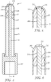
- Fig. 1 shows a device 1 for dispensing a dental material according to one embodiment of the invention.
- the device has a container 11 for holding the dental material.
- a piston 12 is arranged movably within the container 11.
- the device 1 has a spindle 13 arranged for cooperation with the piston 12.
- the piston 12 is received on a front end 131 of the spindle 13.
- the spindle 13 and the container 11 are connected by a threaded connection with each other and rotatable about a rotation axis A relative to each other. Therefore by rotating the spindle 13 and the container 11 relative to each other the spindle 13 and the container 11 move axially relative to each other.
- the device 1 may have a reverse lock (not shown) which prevents the spindle 13 and the container 11 from being rotated in an opposite second direction.
- the piston 12 may be prevented from being retracted. This may for example avoid air to be pulled into the device 1 which may help maximizing the shelf life of material remaining in the device 1.
- Fig. 2 shows the piston 12 and the spindle 13 in a first axial position relative to each other.
- an engagement structure 135 of the spindle 13 engages with an engagement structure 125 of the piston 12 so that the piston 12 and the spindle 13 are rotationally locked with each other.
- the spindle engagement structure 135 is formed by a protrusion extending generally parallel to the rotation axis A but which is arranged in an off-center relationship with the rotation axis A.
- the protrusion engages a blind hole in the piston 12 which also extends into the piston 12 generally parallel to the rotation axis A and which is arranged in an off-center relationship with the rotation axis A.
- the second axial position of the piston 12 and the spindle as shown in Fig. 3 is preferably established during dispensing the dental material. Accordingly the spindle 13 may be rotated relative to the container 11 so that the spindle 13 is screwed into the container 11, thereby pushing the piston 12 forward for dispensing the dental material. Because in the second axial position the piston 12 and the spindle 13 are rotatable relative to each other the piston 12, preferably being press fit in the container 11 for tight sealing, does not rotate relative to the container 11. Thus the force for rotating the spindle 13 and the container 11 relative to each other may be minimized relative to a configuration in which the piston is not rotatable relative to the spindle.
- the second axial position of the piston 12 and the spindle 13 is initially established in a situation in which the container is full of dental material, meaning at a stage at which still nothing of the dental material contained in the device 1 has been dispensed therefrom.
- This may be provided by the manufacturer of the device 1, for example.
- the device is adapted such that the piston 12 and the spindle 13 remain in the second axial position as long as an axial force urging the piston 11 and the spindle 13 toward each other are within a range of 0 N to about a threshold force of 1000 N, more preferably within a range of 0 N to about a threshold force of 500 N, and most preferably within a range of 0 N to about a threshold force of 200 N.
- the device 1 is further adapted such that, upon exceeding the threshold force, the piston 11 and the spindle 13 move into the first axial position.
- the spindle front end 131 comprises a first section 132, a second section 133 and a third section 134
- the piston 12 comprises a receptacle 126 having a first section 122 and a second section 123.
- the spindle first, second and third section 132, 133, 134 are arranged with the spindle first section 132 arranged adjacent the spindle front end 131, the spindle third section 134 further toward a rear end 137 of the spindle 13, and with the spindle second section 133 arranged between the spindle first and third section 132, 134.
- the spindle first, second and third section 132, 133, 134 are arranged directly adjacent each other without a space or other section arranged between.
- the piston has a front end 121 and a rear end 127, and the receptacle 126 extends from the piston rear end 127 into the piston 12 in a direction toward the piston front end 121.
- the piston first section 122 is arranged adjacent the piston rear end 127 and the piston second section 123 is arranged further toward the piston front end.
- the piston first section 122 and the piston second section 123 are arranged directly adjacent each other without a space or other section arranged between.
- the spindle first section 132 comprises the spindle engagement structure 135. Further the spindle second section 133 is formed by a generally cylindrical portion of the spindle 13, and the spindle third section 134 is formed by a bulge or rim of a greater diameter than the cylindrical portion of the spindle second section 133.
- piston first section 122 is formed by a generally cylindrical portion of the receptacle 126 of the piston 12, whereas the piston second section 123 comprises the engagement structure 125.
- the spindle 13 is located with its front end 131 inside the container and the spindle rear end 137 outside the container 11.
- a threaded nut 14 may be fixed within the container 11 and a rear end 111 of the container 11.
- the threaded nut 14 may be press fit and/or glued into the container 11.
- the threaded nut 14 may be welded, snap fit, or screwed with the container. Other connections may be used as appropriate.
- the container 11 has preferably at its front end 112 has a dispensing outlet 113 for the dental material. Therefore in operation of the device 1 the spindle 13 and the container 11 may be rotated relative to each other for dispensing the dental material from the device 1.
- a further operation of the device 1 to dispense material causes the piston 12 to be pressurized between the spindle 13 and consequently an axial force urging the piston 12 and the spindle 13 toward one another to increase.
- the piston 12 and the spindle 13 move from the second to the first axial position.
- a further rotation of the spindle 13 and the container 11 relative to each other causes the piston 12 to also rotate. Therefore any material between the piston front end 121 and the inner container front end 112 is striped off in the area of the outlet 113 as the piston 12 rotates relative to the outlet 113.
- the device 1 is advantageous in that it can be substantially entirely emptied.
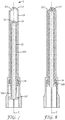
- Fig. 4 shows a device 2 according to a further embodiment of the invention.
- the device 2 has a container 21 for holding a dental material.
- a piston 22 is movably arranged within the container 21.
- a spindle 23 is arranged within the device 2 for cooperation with the piston 22.
- the piston 22 is received on the spindle 23.
- the spindle 23 and the container 21 are arranged axially stationary but rotatable relative to each other.
- the spindle 23 has a front end 231 having an engagement structure 235 adjacent the front end 231 and an outer thread 233 between the front end 231 and a rear end 237 of the spindle 23.
- the piston 22 has a front end 221 and a rear end 227 and a through-hole 226 extending between the front end 221 and the rear end 227.
- the piston 22 forms within the through-hole 226 an inner thread for engagement with the outer thread 233 of the spindle 23.
- the piston 22 has further an engagement structure 225 adjacent the front end 221 of the piston 22.
- the piston 22 and the spindle 23 are adapted for optionally anti-twist locking against each other.
- the engagement structures 235, 225 of the spindle 23 and the piston 22 are engaged with one another, and in a second axial position, as shown in Fig. 6 , the engagement structures 235, 225 of the spindle 23 and the piston 22 are disengaged from each other.
- the engagement structure 235 of the spindle 23 engages with the engagement structure 225 of the piston 22 so that the piston 22 and the spindle 23 are rotationally locked with each other.
- the spindle engagement structure 235 is a non-cylindrical structure which outer periphery protrudes over an outer diameter of the spindle thread 233.
- the non-cylindrical structure is formed by a web which protrudes form the spindle 23 in a dimension laterally of the rotation axis B.
- the spindle 23 and the piston 22 are rotatable such that spindle 23 and the piston 22 can be screwed with one another. Accordingly in the second axial position the spindle 23 and the piston 22 can be rotated relative to each other for dispensing the dental material.
- the piston 22 is preferably press fit within the container 21. Thus a tight seal between the container 21 and the piston is formed.
- the piston 22 and the container 21 are rotationally retained relative to each other, preferably due friction forces. Therefore a rotation of the spindle 23 relative to the container 21 normally causes also a rotation of the spindle 23 relative to the piston 22. Hence the dental material can be dispensed by a rotation of the spindle 23 relative to the container 21 in the second axial position of the spindle 23 and the piston 22.
- the container 21 has at its front end 212 has a dispensing outlet 213 for the dental material. Therefore in operation of the device 2 the spindle 23 and the container 21 may be rotated relative to each other for dispensing the dental material from the device 2. Further the spindle 23 is located inside the container 21 and the spindle rear end 227 is located outside the container. The spindle 23 has a length so that the spindle front end 231 is located adjacent the container front end 212. Accordingly in operation of the device for dispensing material, once the piston 22 has reached the front end 231 of the spindle 23 the engagement structure 235, 225 of the spindle 23 and the piston 22, respectively, engage with each other so that the first axial position is established.
- Fig. 7 shows a device 3 according to the background of the invention.
- the device 3 has a container 31 for holding a dental material.
- a piston 32 is movably arranged within the container 31.
- the piston 32 is integral part of a spindle 33.
- the spindle 33 and the container 31 are connected by a threaded connection with each other and rotatable about a rotation axis C relative to each other.
- the threaded connection between the spindle 33 and the container 31 is configured for disengaging in a first axial position of the spindle relative to the container 31, whereas in a second axial position the threaded connection is in engagement.
- a piston front end 321 is in contact or close proximity to a front end 312 of the container (illustrated in Fig. 8 ).
- any space between the piston 32 and the container 31 is substantially eliminated so that substantially all material initially contained in the container 31 is displaced therefrom.
- the groove 338 is dimensioned smaller in diameter than the minor thread diameter of the outer thread 333.
- a threaded nut 34 is attached to the container 31. In the second axial position of the spindle 33 and the container 31 the thread of the nut 34 and the outer thread 333 of the spindle 33 are engaged, whereas in the first axial position of the spindle 33 and the container 31 the thread of the nut 34 cooperates with the groove 338 of the spindle 33 so that the threaded connection between the spindle 33 and the container 31 is suspended. Therefore in the first axial position the spindle 33 and the container 31 can be rotated relative to each other without causing any (further) axial movement between the spindle 33 and the container 31.
- the spindle 33 and the container 31 may be rotated relative to each other for dispensing the dental material from the device 3.
- a further operation of the device 3 to dispense material causes the spindle 33 and the container 31 to reach the first axial position and the threaded connection between the spindle 33 and the container 31 to disengage.
- the first axial position a further rotation of the spindle 33 and the container 31 relative to each other causes the piston 32 to rotate without axial further movement. Therefore any material between the piston front end 321 and the inner container front end 312 is striped off in the area of an outlet 313 as the piston 32 rotates relative to the outlet 313.
- the device 3 is advantageous in that it can be substantially entirely emptied.
Landscapes
- Engineering & Computer Science (AREA)
- Mechanical Engineering (AREA)
- Health & Medical Sciences (AREA)
- Oral & Maxillofacial Surgery (AREA)
- Dentistry (AREA)
- Epidemiology (AREA)
- Life Sciences & Earth Sciences (AREA)
- Animal Behavior & Ethology (AREA)
- General Health & Medical Sciences (AREA)
- Public Health (AREA)
- Veterinary Medicine (AREA)
- Dental Tools And Instruments Or Auxiliary Dental Instruments (AREA)
Claims (10)
- Dispositif (1) pour distribuer un matériau comprenant un récipient (11) destiné à contenir le matériau, un piston (12) disposé de manière mobile dans le récipient (11) et une tige (13) en coopération avec le piston (12), dans lequel le dispositif (1) est configuré de telle sorte que la tige (13) et le récipient (11) peuvent tourner autour d'un axe de rotation (A) l'un par rapport à l'autre pour déplacer le piston (12) pour distribuer le matériau, et dans lequel le piston (12) et la tige (13) sont adaptés pour ne pas se torsionner l'un avec l'autre dans une première position axiale du piston (12) par rapport à la tige (13), et dans lequel dans une deuxième position axiale du piston (12) par rapport à la tige (13) le verrouillage anti-torsion entre le piston (12) et la tige (13) est suspendu, avec la première et deuxième position axiale en référence à deux positions différentes dans une dimension de l'axe de rotation (A), caractérisé en ce que la tige (13) et le récipient (11) sont en prise par filetage l'un avec l'autre de telle sorte qu'une rotation de la tige (13) et du récipient (11) l'un par rapport à l'autre fait en sorte que la tige (13) se déplace axialement par rapport au récipient (11), dans lequel une extrémité avant (131) de la tige est située à l'intérieur du récipient (11) et une extrémité arrière (137) de la tige (13) est située à l'extérieur du récipient (11), l'extrémité avant (131) comprenant une direction de l'extrémité avant (131) vers l'extrémité arrière (137) une première section (132), une deuxième section (133) et une troisième section (134) disposées consécutivement dans l'ordre indiqué, et dans lequel le piston a une extrémité avant (121) et une extrémité arrière (127) avec un réceptacle (126) s'étendant de l'extrémité arrière (127) à l'intérieur du piston (12), le réceptacle (126) ayant une première section (122) adjacente à l'extrémité arrière du piston (127) et une deuxième section (123) plus loin vers l'extrémité avant du piston (121), et dans laquelle dans la première position axiale du piston (12) et de la tige (13) la deuxième section du piston (123) est en prise avec la première section de la tige (132), et dans la deuxième position axiale du piston (12) et de la tige (13) la deuxième section du piston (123) et la première section de la tige (132) sont libérées l'une de l'autre.
- Dispositif selon la revendication 1, comprenant, en outre, un écrou (14) ayant un filetage interne étant en prise avec un filetage externe de la tige (13), dans lequel l'écrou (14) est connecté de manière fixe au récipient (11).
- Dispositif selon la revendication 1 ou 2, dans lequel dans la première position axiale du piston (12) et de la tige (13) la première section du piston (122) est en outre accouplée avec la deuxième et la troisième section de la tige (133, 134), alors que dans la deuxième position axiale du piston (12) et de la tige (13) la première section du piston (122) est accouplée avec la deuxième section de la tige (133), mais pas avec la troisième section de la tige (134).
- Dispositif de l'une quelconque des revendications précédentes, dans lequel la deuxième section du piston (123) et la première section de la tige (132) sont profilées de telle sorte que dans une situation dans laquelle la deuxième section du piston (123) et la première section de la tige (132) sont accouplées elles forment un verrouillage anti-torsion pour le piston (12) et la tige (13) l'un par rapport à l'autre.
- Dispositif de l'une quelconque des revendications précédentes, dans lequel la première section du piston (122) et la deuxième section de la tige (133) sont adaptées pour former un ajustement rotatif l'une avec l'autre, pour une rotation du piston (12) et de la tige (13) l'un par rapport à l'autre.
- Dispositif de l'une quelconque des revendications précédentes, dans lequel la première section du piston (122) et la troisième section de la tige (134) sont adaptées pour former un ajustage à presse l'une avec l'autre.
- Dispositif de l'une quelconque des revendications précédentes, dans lequel le piston (12) est reçu avec le réceptacle (126) sur l'extrémité avant (131) de la tige.
- Dispositif (2) pour distribuer un matériau, comprenant un récipient (21) pour contenir le matériau, un piston (22) disposé de manière mobile dans le récipient (21) et une tige (23) en coopération avec le piston (22), dans lequel le dispositif (2) est configuré de telle sorte que la tige (23) et le récipient (21) peuvent tourner autour d'un axe de rotation (B) l'un par rapport à l'autre pour déplacer le piston (22) pour distribuer le matériau, et dans lequel le piston (22) et la tige (23) sont adaptés pour ne pas se torsionner l'un avec l'autre dans une première position axiale du piston (22) par rapport à la tige (23), et dans lequel dans une deuxième position axiale du piston (22) par rapport à la tige (23) le verrouillage anti-torsion entre le piston (22) et la tige (23) est suspendu, avec la première et deuxième position axiale en référence à deux positions différentes dans une dimension de l'axe de rotation (B), dans lequel la tige (23) est reçue en sens axial fixe, mais peut tourner dans le récipient (21), et dans lequel dans la deuxième position axiale du piston (22) et de la tige (23) le piston (22) et la tige (23) sont en prise directement ou indirectement par filetage l'un avec l'autre et le piston (22) et le récipient (21) sont retenus en rotation l'un par rapport à l'autre, de telle sorte qu'une rotation de la tige (23) et du récipient (21) l'un par rapport à l'autre entraîne le piston (22), à se déplacer axialement par rapport au récipient (21), dans lequel la tige (23) a une extrémité avant (231) étant située à l'intérieur du récipient (21) et une extrémité arrière (237) située à l'extérieur du récipient (21), la tige (23) comprenant une structure de mise en prise (235) adjacente à l'extrémité avant (231) et un filetage externe entre l'extrémité avant et arrière (231, 237), caractérisée en ce que le piston (22) possédant une extrémité avant (221) et une extrémité arrière (227) et un orifice traversant (226) s'étendant au milieu et formant un filetage interne pour une mise en prise avec le filetage de tige externe (233), le piston ayant en outre une structure de mise en prise (225) adjacente à l'extrémité avant du piston (221), et dans lequel dans la première position axiale du piston (22) et de la tige (23) les structures de mise en prise (225, 235) de la tige (23) et du piston (22) sont en prise l'une avec l'autre, et dans la deuxième position axiale du piston (22) et de la tige (23) les structures de mise en prise (225, 235) du piston (22) et de la tige (23) sont libérées l'une de l'autre.
- Dispositif (1, 2) de l'une quelconque des revendications précédentes, dans lequel dans la deuxième position axiale un volume pour le matériau est formé entre le récipient (11, 21) et le piston (12, 22), alors que dans la première position axiale un tel volume est éliminé.
- Dispositif (1, 2) de l'une quelconque des revendications précédentes, dans lequel le récipient (11, 21) a une extrémité avant (112, 212) et une extrémité arrière opposée et la tige (13, 23) s'étend dans l'extrémité arrière du récipient, le récipient (11, 21) ayant une sortie (113, 213) pour le matériau à l'extrémité avant (112, 212).
Applications Claiming Priority (2)
| Application Number | Priority Date | Filing Date | Title |
|---|---|---|---|
| EP14156858 | 2014-02-26 | ||
| PCT/US2015/017438 WO2015130739A1 (fr) | 2014-02-26 | 2015-02-25 | Dispositif de distribution d'un matériau |
Publications (2)
| Publication Number | Publication Date |
|---|---|
| EP3131685A1 EP3131685A1 (fr) | 2017-02-22 |
| EP3131685B1 true EP3131685B1 (fr) | 2020-04-08 |
Family
ID=50159142
Family Applications (1)
| Application Number | Title | Priority Date | Filing Date |
|---|---|---|---|
| EP15708097.9A Active EP3131685B1 (fr) | 2014-02-26 | 2015-02-25 | Dispositif de distribution d'un matériau |
Country Status (3)
| Country | Link |
|---|---|
| US (1) | US10478852B2 (fr) |
| EP (1) | EP3131685B1 (fr) |
| WO (1) | WO2015130739A1 (fr) |
Families Citing this family (2)
| Publication number | Priority date | Publication date | Assignee | Title |
|---|---|---|---|---|
| EP3302346B1 (fr) | 2015-05-29 | 2019-03-20 | 3M Innovative Properties Company | Dispositif de distribution de matériau dentaire |
| KR102300088B1 (ko) * | 2020-04-20 | 2021-09-08 | 공주대학교 산학협력단 | 막힘 방지 기능을 갖는 비대칭형 액상물질 주입장치 |
Family Cites Families (17)
| Publication number | Priority date | Publication date | Assignee | Title |
|---|---|---|---|---|
| DE419236C (de) | 1925-10-02 | Allg Elek Citaets Ges Fa | Hochspannungszuendapparat zum Betriebe von Explosionsmotoren | |
| GB999506A (en) * | 1960-11-02 | 1965-07-28 | Engis Ltd | Improvements in syringes for dispensing paste or the like |
| US4312343A (en) * | 1979-07-30 | 1982-01-26 | Leveen Harry H | Syringe |
| DE3212187A1 (de) * | 1982-04-01 | 1983-10-06 | Espe Pharm Praep | Vorrichtung zum dosierten ausbringen von dentalmassen |
| DE9406342U1 (de) * | 1994-04-15 | 1995-08-17 | Mühlbauer, Ernst, 22547 Hamburg | Vorratsspritze für Dentalmasse |
| CN1099266C (zh) | 1994-04-27 | 2003-01-22 | 汉克尔股份两合公司 | 用于涂抹粘合剂等物料的可重复使用的容器 |
| AU736606B2 (en) * | 1997-10-20 | 2001-08-02 | Prc-Desoto International, Inc. | Multiple part manual dispensing syringe |
| USD419236S (en) | 1998-10-02 | 2000-01-18 | 3M Innovative Properties Company | Syringe-type applicator |
| US6436075B1 (en) * | 2000-10-18 | 2002-08-20 | Hsueh-Cheng Liao | Syringe |
| US6571992B2 (en) * | 2001-01-12 | 2003-06-03 | Dentsply Research & Development Corp. | Dispensing syringe |
| US6547432B2 (en) * | 2001-07-16 | 2003-04-15 | Stryker Instruments | Bone cement mixing and delivery device for injection and method thereof |
| JP3857963B2 (ja) | 2002-07-30 | 2006-12-13 | エム・エフ・ヴィ株式会社 | 収納容器 |
| AU2005231716B2 (en) * | 2004-03-31 | 2010-08-05 | Izi Medical Products, Llc | Apparatus for an improved high pressure medicinal dispenser |
| US7261559B2 (en) | 2005-04-01 | 2007-08-28 | Ultradent Products, Inc. | Syringe delivery system for dispensing a dental composite or other highly viscous material |
| US8394105B2 (en) * | 2006-03-14 | 2013-03-12 | DePuy Synthes Products, LLC | Apparatus for dispensing bone cement |
| DE102011005919A1 (de) * | 2011-03-22 | 2012-09-27 | Voco Gmbh | Drehspritze sowie Spritzenkörper und Mutterteil für eine Drehspritze |
| WO2014136759A1 (fr) * | 2013-03-08 | 2014-09-12 | ニプロ株式会社 | Seringue et joint de seringue |
-
2015
- 2015-02-25 WO PCT/US2015/017438 patent/WO2015130739A1/fr not_active Ceased
- 2015-02-25 EP EP15708097.9A patent/EP3131685B1/fr active Active
- 2015-02-25 US US15/119,300 patent/US10478852B2/en active Active
Non-Patent Citations (1)
| Title |
|---|
| None * |
Also Published As
| Publication number | Publication date |
|---|---|
| EP3131685A1 (fr) | 2017-02-22 |
| US10478852B2 (en) | 2019-11-19 |
| WO2015130739A1 (fr) | 2015-09-03 |
| US20170050210A1 (en) | 2017-02-23 |
Similar Documents
| Publication | Publication Date | Title |
|---|---|---|
| US8613372B2 (en) | Dispensing cap for a container | |
| JP6061921B2 (ja) | 容器の内容物に添加物を導入するための手段を有する容器閉鎖具 | |
| EP0284244B1 (fr) | Distributeur de liquides visqueux | |
| EP2727656B1 (fr) | Dispositif de stockage et de distribution | |
| US8206050B2 (en) | Dispenser having an anti-rotation piston | |
| US10065775B2 (en) | Dispensing cap for a container | |
| US10464089B2 (en) | Dispenser for liquid to pasty substances | |
| EP3002496B1 (fr) | Pistolet à graisse | |
| EP3131685B1 (fr) | Dispositif de distribution d'un matériau | |
| EP3131493B1 (fr) | Capsule de mélange et de distribution d'un matériau dentaire | |
| US10196196B2 (en) | Watertight liquid dispenser with syringe-like functions | |
| EP2461717B1 (fr) | Distributeur de matières visqueuses | |
| CN114727696A (zh) | 分配器 | |
| CN106660064A (zh) | 用于多筒管的转动式配制器 | |
| MX2011005209A (es) | Sistema de cierre entre un cabezal de distribucion y un recipiente para despachar liquido. | |
| US20120322028A1 (en) | Dental syringe | |
| US10675414B2 (en) | Syringe for viscous fluids | |
| JP2020146366A (ja) | 化粧料塗布具 | |
| EP2468657B1 (fr) | Dispositif pour distribuer des substances fluides, en particulier des crèmes | |
| JP5297794B2 (ja) | 吐出容器 | |
| EP4613669A1 (fr) | Récipient de distribution | |
| WO2018147721A1 (fr) | Distributeur de fluide | |
| EP4039298B1 (fr) | Dispositif obturateur à oscillation automatique | |
| GB2506352A (en) | Dispenser with self-adjusting thread member |
Legal Events
| Date | Code | Title | Description |
|---|---|---|---|
| STAA | Information on the status of an ep patent application or granted ep patent |
Free format text: STATUS: THE INTERNATIONAL PUBLICATION HAS BEEN MADE |
|
| PUAI | Public reference made under article 153(3) epc to a published international application that has entered the european phase |
Free format text: ORIGINAL CODE: 0009012 |
|
| STAA | Information on the status of an ep patent application or granted ep patent |
Free format text: STATUS: REQUEST FOR EXAMINATION WAS MADE |
|
| 17P | Request for examination filed |
Effective date: 20160823 |
|
| AK | Designated contracting states |
Kind code of ref document: A1 Designated state(s): AL AT BE BG CH CY CZ DE DK EE ES FI FR GB GR HR HU IE IS IT LI LT LU LV MC MK MT NL NO PL PT RO RS SE SI SK SM TR |
|
| AX | Request for extension of the european patent |
Extension state: BA ME |
|
| DAX | Request for extension of the european patent (deleted) | ||
| STAA | Information on the status of an ep patent application or granted ep patent |
Free format text: STATUS: EXAMINATION IS IN PROGRESS |
|
| 17Q | First examination report despatched |
Effective date: 20190429 |
|
| RIC1 | Information provided on ipc code assigned before grant |
Ipc: B05C 17/005 20060101AFI20191113BHEP Ipc: A61C 5/62 20170101ALI20191113BHEP Ipc: B05C 17/01 20060101ALI20191113BHEP |
|
| GRAP | Despatch of communication of intention to grant a patent |
Free format text: ORIGINAL CODE: EPIDOSNIGR1 |
|
| STAA | Information on the status of an ep patent application or granted ep patent |
Free format text: STATUS: GRANT OF PATENT IS INTENDED |
|
| INTG | Intention to grant announced |
Effective date: 20200107 |
|
| GRAS | Grant fee paid |
Free format text: ORIGINAL CODE: EPIDOSNIGR3 |
|
| GRAA | (expected) grant |
Free format text: ORIGINAL CODE: 0009210 |
|
| STAA | Information on the status of an ep patent application or granted ep patent |
Free format text: STATUS: THE PATENT HAS BEEN GRANTED |
|
| AK | Designated contracting states |
Kind code of ref document: B1 Designated state(s): AL AT BE BG CH CY CZ DE DK EE ES FI FR GB GR HR HU IE IS IT LI LT LU LV MC MK MT NL NO PL PT RO RS SE SI SK SM TR |
|
| REG | Reference to a national code |
Ref country code: AT Ref legal event code: REF Ref document number: 1253648 Country of ref document: AT Kind code of ref document: T Effective date: 20200415 Ref country code: CH Ref legal event code: EP |
|
| REG | Reference to a national code |
Ref country code: DE Ref legal event code: R096 Ref document number: 602015050216 Country of ref document: DE |
|
| REG | Reference to a national code |
Ref country code: IE Ref legal event code: FG4D |
|
| REG | Reference to a national code |
Ref country code: NL Ref legal event code: MP Effective date: 20200408 |
|
| REG | Reference to a national code |
Ref country code: LT Ref legal event code: MG4D |
|
| PG25 | Lapsed in a contracting state [announced via postgrant information from national office to epo] |
Ref country code: GR Free format text: LAPSE BECAUSE OF FAILURE TO SUBMIT A TRANSLATION OF THE DESCRIPTION OR TO PAY THE FEE WITHIN THE PRESCRIBED TIME-LIMIT Effective date: 20200709 Ref country code: IS Free format text: LAPSE BECAUSE OF FAILURE TO SUBMIT A TRANSLATION OF THE DESCRIPTION OR TO PAY THE FEE WITHIN THE PRESCRIBED TIME-LIMIT Effective date: 20200808 Ref country code: NL Free format text: LAPSE BECAUSE OF FAILURE TO SUBMIT A TRANSLATION OF THE DESCRIPTION OR TO PAY THE FEE WITHIN THE PRESCRIBED TIME-LIMIT Effective date: 20200408 Ref country code: SE Free format text: LAPSE BECAUSE OF FAILURE TO SUBMIT A TRANSLATION OF THE DESCRIPTION OR TO PAY THE FEE WITHIN THE PRESCRIBED TIME-LIMIT Effective date: 20200408 Ref country code: LT Free format text: LAPSE BECAUSE OF FAILURE TO SUBMIT A TRANSLATION OF THE DESCRIPTION OR TO PAY THE FEE WITHIN THE PRESCRIBED TIME-LIMIT Effective date: 20200408 Ref country code: NO Free format text: LAPSE BECAUSE OF FAILURE TO SUBMIT A TRANSLATION OF THE DESCRIPTION OR TO PAY THE FEE WITHIN THE PRESCRIBED TIME-LIMIT Effective date: 20200708 Ref country code: PT Free format text: LAPSE BECAUSE OF FAILURE TO SUBMIT A TRANSLATION OF THE DESCRIPTION OR TO PAY THE FEE WITHIN THE PRESCRIBED TIME-LIMIT Effective date: 20200817 Ref country code: FI Free format text: LAPSE BECAUSE OF FAILURE TO SUBMIT A TRANSLATION OF THE DESCRIPTION OR TO PAY THE FEE WITHIN THE PRESCRIBED TIME-LIMIT Effective date: 20200408 |
|
| REG | Reference to a national code |
Ref country code: AT Ref legal event code: MK05 Ref document number: 1253648 Country of ref document: AT Kind code of ref document: T Effective date: 20200408 |
|
| PG25 | Lapsed in a contracting state [announced via postgrant information from national office to epo] |
Ref country code: HR Free format text: LAPSE BECAUSE OF FAILURE TO SUBMIT A TRANSLATION OF THE DESCRIPTION OR TO PAY THE FEE WITHIN THE PRESCRIBED TIME-LIMIT Effective date: 20200408 Ref country code: LV Free format text: LAPSE BECAUSE OF FAILURE TO SUBMIT A TRANSLATION OF THE DESCRIPTION OR TO PAY THE FEE WITHIN THE PRESCRIBED TIME-LIMIT Effective date: 20200408 Ref country code: RS Free format text: LAPSE BECAUSE OF FAILURE TO SUBMIT A TRANSLATION OF THE DESCRIPTION OR TO PAY THE FEE WITHIN THE PRESCRIBED TIME-LIMIT Effective date: 20200408 Ref country code: BG Free format text: LAPSE BECAUSE OF FAILURE TO SUBMIT A TRANSLATION OF THE DESCRIPTION OR TO PAY THE FEE WITHIN THE PRESCRIBED TIME-LIMIT Effective date: 20200708 |
|
| PG25 | Lapsed in a contracting state [announced via postgrant information from national office to epo] |
Ref country code: AL Free format text: LAPSE BECAUSE OF FAILURE TO SUBMIT A TRANSLATION OF THE DESCRIPTION OR TO PAY THE FEE WITHIN THE PRESCRIBED TIME-LIMIT Effective date: 20200408 |
|
| REG | Reference to a national code |
Ref country code: DE Ref legal event code: R097 Ref document number: 602015050216 Country of ref document: DE |
|
| PG25 | Lapsed in a contracting state [announced via postgrant information from national office to epo] |
Ref country code: IT Free format text: LAPSE BECAUSE OF FAILURE TO SUBMIT A TRANSLATION OF THE DESCRIPTION OR TO PAY THE FEE WITHIN THE PRESCRIBED TIME-LIMIT Effective date: 20200408 Ref country code: AT Free format text: LAPSE BECAUSE OF FAILURE TO SUBMIT A TRANSLATION OF THE DESCRIPTION OR TO PAY THE FEE WITHIN THE PRESCRIBED TIME-LIMIT Effective date: 20200408 Ref country code: RO Free format text: LAPSE BECAUSE OF FAILURE TO SUBMIT A TRANSLATION OF THE DESCRIPTION OR TO PAY THE FEE WITHIN THE PRESCRIBED TIME-LIMIT Effective date: 20200408 Ref country code: SM Free format text: LAPSE BECAUSE OF FAILURE TO SUBMIT A TRANSLATION OF THE DESCRIPTION OR TO PAY THE FEE WITHIN THE PRESCRIBED TIME-LIMIT Effective date: 20200408 Ref country code: CZ Free format text: LAPSE BECAUSE OF FAILURE TO SUBMIT A TRANSLATION OF THE DESCRIPTION OR TO PAY THE FEE WITHIN THE PRESCRIBED TIME-LIMIT Effective date: 20200408 Ref country code: EE Free format text: LAPSE BECAUSE OF FAILURE TO SUBMIT A TRANSLATION OF THE DESCRIPTION OR TO PAY THE FEE WITHIN THE PRESCRIBED TIME-LIMIT Effective date: 20200408 Ref country code: DK Free format text: LAPSE BECAUSE OF FAILURE TO SUBMIT A TRANSLATION OF THE DESCRIPTION OR TO PAY THE FEE WITHIN THE PRESCRIBED TIME-LIMIT Effective date: 20200408 Ref country code: ES Free format text: LAPSE BECAUSE OF FAILURE TO SUBMIT A TRANSLATION OF THE DESCRIPTION OR TO PAY THE FEE WITHIN THE PRESCRIBED TIME-LIMIT Effective date: 20200408 |
|
| PLBE | No opposition filed within time limit |
Free format text: ORIGINAL CODE: 0009261 |
|
| STAA | Information on the status of an ep patent application or granted ep patent |
Free format text: STATUS: NO OPPOSITION FILED WITHIN TIME LIMIT |
|
| PG25 | Lapsed in a contracting state [announced via postgrant information from national office to epo] |
Ref country code: PL Free format text: LAPSE BECAUSE OF FAILURE TO SUBMIT A TRANSLATION OF THE DESCRIPTION OR TO PAY THE FEE WITHIN THE PRESCRIBED TIME-LIMIT Effective date: 20200408 Ref country code: SK Free format text: LAPSE BECAUSE OF FAILURE TO SUBMIT A TRANSLATION OF THE DESCRIPTION OR TO PAY THE FEE WITHIN THE PRESCRIBED TIME-LIMIT Effective date: 20200408 |
|
| 26N | No opposition filed |
Effective date: 20210112 |
|
| PG25 | Lapsed in a contracting state [announced via postgrant information from national office to epo] |
Ref country code: SI Free format text: LAPSE BECAUSE OF FAILURE TO SUBMIT A TRANSLATION OF THE DESCRIPTION OR TO PAY THE FEE WITHIN THE PRESCRIBED TIME-LIMIT Effective date: 20200408 |
|
| PG25 | Lapsed in a contracting state [announced via postgrant information from national office to epo] |
Ref country code: MC Free format text: LAPSE BECAUSE OF FAILURE TO SUBMIT A TRANSLATION OF THE DESCRIPTION OR TO PAY THE FEE WITHIN THE PRESCRIBED TIME-LIMIT Effective date: 20200408 |
|
| GBPC | Gb: european patent ceased through non-payment of renewal fee |
Effective date: 20210225 |
|
| REG | Reference to a national code |
Ref country code: BE Ref legal event code: MM Effective date: 20210228 |
|
| PG25 | Lapsed in a contracting state [announced via postgrant information from national office to epo] |
Ref country code: LU Free format text: LAPSE BECAUSE OF NON-PAYMENT OF DUE FEES Effective date: 20210225 Ref country code: LI Free format text: LAPSE BECAUSE OF NON-PAYMENT OF DUE FEES Effective date: 20210228 Ref country code: CH Free format text: LAPSE BECAUSE OF NON-PAYMENT OF DUE FEES Effective date: 20210228 |
|
| PG25 | Lapsed in a contracting state [announced via postgrant information from national office to epo] |
Ref country code: FR Free format text: LAPSE BECAUSE OF NON-PAYMENT OF DUE FEES Effective date: 20210228 Ref country code: IE Free format text: LAPSE BECAUSE OF NON-PAYMENT OF DUE FEES Effective date: 20210225 Ref country code: GB Free format text: LAPSE BECAUSE OF NON-PAYMENT OF DUE FEES Effective date: 20210225 |
|
| PG25 | Lapsed in a contracting state [announced via postgrant information from national office to epo] |
Ref country code: BE Free format text: LAPSE BECAUSE OF NON-PAYMENT OF DUE FEES Effective date: 20210228 |
|
| PG25 | Lapsed in a contracting state [announced via postgrant information from national office to epo] |
Ref country code: HU Free format text: LAPSE BECAUSE OF FAILURE TO SUBMIT A TRANSLATION OF THE DESCRIPTION OR TO PAY THE FEE WITHIN THE PRESCRIBED TIME-LIMIT; INVALID AB INITIO Effective date: 20150225 |
|
| PG25 | Lapsed in a contracting state [announced via postgrant information from national office to epo] |
Ref country code: CY Free format text: LAPSE BECAUSE OF FAILURE TO SUBMIT A TRANSLATION OF THE DESCRIPTION OR TO PAY THE FEE WITHIN THE PRESCRIBED TIME-LIMIT Effective date: 20200408 |
|
| REG | Reference to a national code |
Ref country code: DE Ref legal event code: R081 Ref document number: 602015050216 Country of ref document: DE Owner name: SOLVENTUM INTELLECTUAL PROPERTIES CO. (N.D.GES, US Free format text: FORMER OWNER: 3M INNOVATIVE PROPERTIES COMPANY, ST. PAUL, MN, US |
|
| PG25 | Lapsed in a contracting state [announced via postgrant information from national office to epo] |
Ref country code: MK Free format text: LAPSE BECAUSE OF FAILURE TO SUBMIT A TRANSLATION OF THE DESCRIPTION OR TO PAY THE FEE WITHIN THE PRESCRIBED TIME-LIMIT Effective date: 20200408 |
|
| PG25 | Lapsed in a contracting state [announced via postgrant information from national office to epo] |
Ref country code: TR Free format text: LAPSE BECAUSE OF FAILURE TO SUBMIT A TRANSLATION OF THE DESCRIPTION OR TO PAY THE FEE WITHIN THE PRESCRIBED TIME-LIMIT Effective date: 20200408 |
|
| PG25 | Lapsed in a contracting state [announced via postgrant information from national office to epo] |
Ref country code: MT Free format text: LAPSE BECAUSE OF FAILURE TO SUBMIT A TRANSLATION OF THE DESCRIPTION OR TO PAY THE FEE WITHIN THE PRESCRIBED TIME-LIMIT Effective date: 20200408 |
|
| PGFP | Annual fee paid to national office [announced via postgrant information from national office to epo] |
Ref country code: DE Payment date: 20260121 Year of fee payment: 12 |