EP3131774B1 - Dispositif de réglage de lames pivotantes d'un aérateur - Google Patents
Dispositif de réglage de lames pivotantes d'un aérateur Download PDFInfo
- Publication number
- EP3131774B1 EP3131774B1 EP15712577.4A EP15712577A EP3131774B1 EP 3131774 B1 EP3131774 B1 EP 3131774B1 EP 15712577 A EP15712577 A EP 15712577A EP 3131774 B1 EP3131774 B1 EP 3131774B1
- Authority
- EP
- European Patent Office
- Prior art keywords
- adjusting element
- extending
- adjusting
- slats
- guide
- Prior art date
- Legal status (The legal status is an assumption and is not a legal conclusion. Google has not performed a legal analysis and makes no representation as to the accuracy of the status listed.)
- Active
Links
Images





Classifications
-
- B—PERFORMING OPERATIONS; TRANSPORTING
- B60—VEHICLES IN GENERAL
- B60H—ARRANGEMENTS OF HEATING, COOLING, VENTILATING OR OTHER AIR-TREATING DEVICES SPECIALLY ADAPTED FOR PASSENGER OR GOODS SPACES OF VEHICLES
- B60H1/00—Heating, cooling or ventilating devices
- B60H1/34—Nozzles; Air-diffusers
- B60H1/3414—Nozzles; Air-diffusers with means for adjusting the air stream direction
- B60H1/3421—Nozzles; Air-diffusers with means for adjusting the air stream direction using only pivoting shutters
-
- B—PERFORMING OPERATIONS; TRANSPORTING
- B60—VEHICLES IN GENERAL
- B60H—ARRANGEMENTS OF HEATING, COOLING, VENTILATING OR OTHER AIR-TREATING DEVICES SPECIALLY ADAPTED FOR PASSENGER OR GOODS SPACES OF VEHICLES
- B60H1/00—Heating, cooling or ventilating devices
- B60H1/34—Nozzles; Air-diffusers
- B60H1/345—Nozzles; Air-diffusers with means for adjusting divergence, convergence or oscillation of air stream
-
- E—FIXED CONSTRUCTIONS
- E04—BUILDING
- E04F—FINISHING WORK ON BUILDINGS, e.g. STAIRS, FLOORS
- E04F21/00—Implements for finishing work on buildings
- E04F21/0076—Implements for finishing work on buildings for marking and cutting tiles
-
- E—FIXED CONSTRUCTIONS
- E04—BUILDING
- E04F—FINISHING WORK ON BUILDINGS, e.g. STAIRS, FLOORS
- E04F21/00—Implements for finishing work on buildings
- E04F21/20—Implements for finishing work on buildings for laying flooring
- E04F21/22—Implements for finishing work on buildings for laying flooring of single elements, e.g. flooring cramps ; flexible webs
-
- F—MECHANICAL ENGINEERING; LIGHTING; HEATING; WEAPONS; BLASTING
- F24—HEATING; RANGES; VENTILATING
- F24F—AIR-CONDITIONING; AIR-HUMIDIFICATION; VENTILATION; USE OF AIR CURRENTS FOR SCREENING
- F24F13/00—Details common to, or for air-conditioning, air-humidification, ventilation or use of air currents for screening
- F24F13/08—Air-flow control members, e.g. louvres, grilles, flaps or guide plates
- F24F13/10—Air-flow control members, e.g. louvres, grilles, flaps or guide plates movable, e.g. dampers
- F24F13/14—Air-flow control members, e.g. louvres, grilles, flaps or guide plates movable, e.g. dampers built up of tilting members, e.g. louvre
- F24F13/15—Air-flow control members, e.g. louvres, grilles, flaps or guide plates movable, e.g. dampers built up of tilting members, e.g. louvre with parallel simultaneously tiltable lamellae
-
- G—PHYSICS
- G01—MEASURING; TESTING
- G01B—MEASURING LENGTH, THICKNESS OR SIMILAR LINEAR DIMENSIONS; MEASURING ANGLES; MEASURING AREAS; MEASURING IRREGULARITIES OF SURFACES OR CONTOURS
- G01B21/00—Measuring arrangements or details thereof, where the measuring technique is not covered by the other groups of this subclass, unspecified or not relevant
- G01B21/20—Measuring arrangements or details thereof, where the measuring technique is not covered by the other groups of this subclass, unspecified or not relevant for measuring contours or curvatures, e.g. determining profile
-
- G—PHYSICS
- G01—MEASURING; TESTING
- G01S—RADIO DIRECTION-FINDING; RADIO NAVIGATION; DETERMINING DISTANCE OR VELOCITY BY USE OF RADIO WAVES; LOCATING OR PRESENCE-DETECTING BY USE OF THE REFLECTION OR RERADIATION OF RADIO WAVES; ANALOGOUS ARRANGEMENTS USING OTHER WAVES
- G01S17/00—Systems using the reflection or reradiation of electromagnetic waves other than radio waves, e.g. lidar systems
- G01S17/88—Lidar systems specially adapted for specific applications
- G01S17/89—Lidar systems specially adapted for specific applications for mapping or imaging
-
- G—PHYSICS
- G06—COMPUTING OR CALCULATING; COUNTING
- G06Q—INFORMATION AND COMMUNICATION TECHNOLOGY [ICT] SPECIALLY ADAPTED FOR ADMINISTRATIVE, COMMERCIAL, FINANCIAL, MANAGERIAL OR SUPERVISORY PURPOSES; SYSTEMS OR METHODS SPECIALLY ADAPTED FOR ADMINISTRATIVE, COMMERCIAL, FINANCIAL, MANAGERIAL OR SUPERVISORY PURPOSES, NOT OTHERWISE PROVIDED FOR
- G06Q50/00—Information and communication technology [ICT] specially adapted for implementation of business processes of specific business sectors, e.g. utilities or tourism
- G06Q50/08—Construction
-
- B—PERFORMING OPERATIONS; TRANSPORTING
- B60—VEHICLES IN GENERAL
- B60H—ARRANGEMENTS OF HEATING, COOLING, VENTILATING OR OTHER AIR-TREATING DEVICES SPECIALLY ADAPTED FOR PASSENGER OR GOODS SPACES OF VEHICLES
- B60H1/00—Heating, cooling or ventilating devices
- B60H1/34—Nozzles; Air-diffusers
- B60H2001/3471—Details of actuators
Definitions
- the present invention relates to a device for adjusting substantially mutually perpendicular slats of a Beerausströmers.
- Air vents as used for example in motor vehicles, generally have mutually perpendicular slats, which can be pivoted either manually or by means of electric drives.
- Air vents in which the slats can be adjusted manually, usually have a mechanism that allows to pivot on the operation of controls both horizontally and vertically slats.
- Air vents that can pivot their blades electrically driven usually have at least two servo motors, wherein a motor causes the adjustment of, for example, horizontally extending fins and a motor, the adjustment of vertically extending fins.
- the electric servomotors can be controlled by push buttons or sensory devices. They are be touch-sensitive control units known, which can be made and changed by touching, for example, a display settings.
- DE 10 2007 035 507 A1 discloses a motor vehicle ventilation device with an air vent, comprising a frame, with horizontal and / or vertical vanes, which are supported by the frame, wherein the frame and / or the vanes are designed to pivot, with at least one pivoting device for pivoting the frame and or the louver, with a sensor device for generating and outputting a sensor signal in response to the movement of a user in the vicinity of the Lucasausströmers and with a control device which is so arranged and coupled to the pivoting device and the sensor device such that the frame and / or the louvers are pivoted by the pivoting device in response to the sensor signal.
- a servomotor for the horizontally extending slats and a servomotor for the vertically extending slats are provided.
- a ventilation nozzle which can be installed in the dashboard of a motor vehicle, with a large number of in each case pivotable about a horizontal axis, forming a lamellae horizontal laminations, with which an outflow opening of a housing is at least partially closed, and with at least one vertical lamella, which is arranged in the outlet region of an opening into the housing outflow channel and with the pivoting about a vertical axis can be deflected by the outflow channel guided air flow, which is designed so that the horizontal and the vertical slats are connected to a drive and in its operation in a predetermined position are pivotable.
- DE 199 56 259 A1 discloses a vehicle air conditioner having an air conditioning unit, wherein temperature settings for air conditioning zones on right and left seat sides can be performed independently of each other.
- the fins running in a common direction of two adjacent air vents can be controlled jointly by a servomotor.
- JP H09 52519 A discloses an air vent having a rotatable adjusting element with a guide groove, wherein in the guide groove, an adjusting element is guided for pivoting of first fins.
- the adjusting element is coupled via a coupling rod with second slats, wherein the second slats are pivoted when the adjusting element is rotated.
- FR 2 861 652 A1 discloses an air vent with a slidably mounted on a rotatably mounted shaft adjustment for pivoting vertical slats. Horizontal slats the Heilausströmers are pivoted about a rotation of a control wheel, wherein the operating wheel is coupled to the shaft.
- a disadvantage of the devices known from the prior art for the adjustment of fins of a Heilausströmers are the variety of components to be used and the required operating movements (longitudinal displacement and / or turning), which is required both in a mechanical and an electrical adjustment .
- At manually adjustable Heilausströmern at least one control element, for example, must be pivoted horizontally and vertically to pivot according to associated slats.
- At Heilausströmern with actuators for the slats at least two servomotors are provided.
- the servomotors execute independent rotational movements.
- a variety of components are required.
- the air vents of the prior art therefore also require a lot of space, for example.
- Object of the present invention is to provide a device for adjusting substantially mutually perpendicular pivotable blades, wherein the number of components required for this reduces over known devices and the adjustment of fins is simplified.
- An inventive device for adjusting substantially mutually perpendicular pivotable blades of a Beerausströmers has a first rotatably mounted adjusting element, wherein the first adjusting element has at least one cylindrical portion, the first adjusting element in the at least one cylindrical section at least one guide, in which a first displacement element is guided, wherein at least one blade extending in a first direction is coupled via the displacement element with the first adjusting element, and at least one in a second direction, perpendicular to the first direction extending blade is coupled to the first adjusting element.
- the device has at least one second rotatably mounted adjusting element, wherein the first adjusting element is coupled to the at least one second adjusting element and the at least one second adjusting element with at least one extending in the second direction lamella, and the axis of rotation of the first adjusting element parallel to the axis of rotation of at least one second adjusting element extends, wherein both the at least one extending in the first direction lamella and the at least one extending in the second direction lamella are pivotable by rotation of the first adjusting element.
- the device allows via the first adjustment pivoting of the extending in the first direction of the louver, wherein on the coupling of the extending in the second direction of the louver with the first adjustment also a pivoting allows the running in the second direction lamella.
- the device thus enables only about the first adjusting a pivoting substantially mutually perpendicular slats.
- the first displacement element is guided, which is, for example, a pin on the extending in the first direction lamella or a displacement element which is coupled with a pin on the extending in the first direction lamella.
- the pin is arranged at a distance to a pivot axis of the lamella running in the first direction, so that a movement of the pin pivots the lamella, wherein the lamella is rotatably supported by its pivot axis in a housing, for example via bearing journals.
- the at least one lamella running in the second direction can be coupled, for example, via coupling elements to the first adjusting element such that the rotation of the rotatably mounted first adjusting element is transferred into a longitudinal movement.
- the lamella extending in the second direction is likewise, like the lamella running in the first direction, mounted rotatably / pivotably in a housing via a pivot extending through its pivot axis and has a pin which is spaced from the pivot axis at the second direction Slat is arranged.
- a longitudinal movement of a coupling element can then cause pivoting of the lamella running in the second direction.
- the device is not limited to the exemplary embodiments given above by way of example and can bring about pivoting of at least one louver extending in the first direction and pivoting of at least one louver extending in the second direction via various means, devices and components it is also possible to pivot a plurality of louvers extending in the first direction and a plurality of louvers extending in the second direction.
- a rotation of the first adjusting element can cause a pivoting of the louvers extending in the first direction and a pivoting of the louvers extending in the second direction, wherein the lamellae can be pivoted in one direction (first and / or second direction) different from each other and only pivoting in the first direction extending slats or pivoting extending in the second direction slats is possible.
- the first adjusting element may comprise a second actuator, which is arranged parallel to a rotational axis of the first adjusting element and the second actuator may be coupled to the at least one extending in the second direction of the fin.
- the first adjusting element may, for example, have a second actuator on an upper surface of the cylindrical portion, wherein the second actuator is coupled to at least one blade extending in a second direction substantially perpendicular to the first direction.
- the second actuator may be a pin or pin which projects from the upper surface and spaced from the axis of rotation of the first adjusting element is arranged.
- the pin is, for example, received in the opening of a coupling rod, wherein the coupling rod has at least one further opening for a pin or pin, which is connected to the extending in the second direction lamella spaced from the pivot axis of the extending in the second direction lamella.
- the opening is formed here as a slot and extends substantially at a right angle to the direction of displacement of the coupling rod.
- the displacement element may also include a first actuator, which is guided in the at least one guide on the outer peripheral surface of the cylindrical portion of the first adjusting element.
- the pivoting of the lamella extending in the first direction is achieved by the at least one guide on the outer circumferential surface of the first adjusting element.
- the first actuator Upon rotation of the first adjusting element, the first actuator is guided in the guide and transmits the movement to the running in the first direction of the blade, which is pivoted according to the guide.
- a change in position of the second actuator takes place when the first adjusting element is rotated.
- the second actuator is coupled to the lamella extending in the second direction, the lamella running in the second direction is pivoted when the adjusting element is rotated.
- the rotation of the first adjustment can be done on the left or right. In this case, depending on the degree of rotation, a corresponding pivoting of the lamella extending in the first direction and a corresponding pivoting of the lamella extending in the second direction result.
- the second actuator may be disposed, for example, on the outer peripheral edge of the upper surface.
- the displacement element can, for example, be displaceable via guide means parallel to the longitudinal axis of the first adjustment element.
- the guide means each ensure that the first displacement element can perform a movement only parallel to the longitudinal axis of the first adjusting element.
- the first displacement element is coupled to the lamella extending in the first direction, so that the longitudinal movement of the displacement element causes pivoting of the lamella extending in the first direction.
- the displacement element has the first actuator, which is guided in the guide of the first adjusting element. If the first adjusting element is rotated about its longitudinal axis, the first actuator moves with the displacement element according to the direction of rotation of the first adjusting element up or down.
- the first adjusting element is coupled to the at least one second adjusting element and the at least one second adjusting element is coupled to at least one louver extending in the second direction.
- the axis of rotation of the at least one second adjusting element extends at an angle of 90 ° to the axis of rotation of the first adjusting element. It can also be provided a plurality of second adjusting elements, for example. About a coupling element are coupled. The rotation of the first adjusting element thus always causes a rotation of the at least one second adjusting element.
- the at least one second adjusting element can also be disk-shaped and the axis of rotation of the at least one second adjusting element can extend parallel to the axis of rotation of the first adjusting element and / or concentric with the axis of rotation of the first adjusting element.
- the diameter of the second adjusting element may be larger, smaller or substantially the same size as the diameter of the cylindrical portion of the first adjusting element.
- the height of the disk-shaped second adjusting element is in most embodiments significantly smaller than the height of the first adjusting element or the cylindrical portion of the first adjusting element.
- first adjusting element and the second adjusting element can also be connected to one another in a manner secured against rotation and / or be formed as a unit.
- the first adjusting element may, for example, have a greater extent in the longitudinal direction along the axis of rotation than the second fixedly connected to the first adjusting element or formed as a unit with this adjusting element.
- the second adjusting element can also have a larger diameter than the first adjusting element. The connection of the first adjusting element with the second adjusting element can take place, for example, via corresponding connecting elements.
- the at least one second adjusting element may have a circumferential gear portion which engages with a circumferential gear portion of the first adjusting element stands.
- the peripheral gear portions may extend both to the entire circumference of a disc-shaped adjusting element and / or a cylindrical portion of an adjusting element as well as only a part of a disc-shaped adjusting element and / or a cylindrical portion of an adjusting.
- the gear cuts may be formed substantially as gears or bevel gears or gear or Kegelradabête. Via the gear portions, a simple coupling of the first adjusting element and the at least one second adjusting element is achieved.
- the gear portions may also be formed so that an over- or reduction of the rotational movement of the first adjusting element or the second adjusting element takes place to the rotational movement of the second adjusting element or the first adjusting element.
- the device may have a plurality of second adjusting elements, wherein the second adjusting elements have a guide and in the guides an adjusting member for pivoting extending in the second direction fins is feasibly received, and wherein the second adjusting elements are coupled together and with the first adjusting element.
- the second adjusting elements are disc-shaped.
- the disc-shaped second adjusting elements have, for example, on their underside the guide and additionally on the opposite upper side a coupling pin, which is arranged at a distance from the axis of rotation of the second adjusting elements.
- the coupling pins of the second adjusting elements are received in openings of a coupling element, such as a coupling rod, and the coupling element has at one end a further opening in which, for example, the second actuator of the first adjusting element is received.
- the further opening is formed for this purpose as a slot and extends orthogonal to the direction of displacement of the coupling rod.
- a second pin which is the adjusting member in this embodiment, is received in the guides of the second adjusting element, the pin being arranged at a distance from the pivoting axis of the lamella running in the second direction.
- the guides in the two adjusting elements can be designed differently, so that in addition to a common pivoting of the extending in the second direction slats by an equal amount, a pivoting about different amounts is possible ("spot" and "diffuse" position in the second Direction running slats).
- the guides can be designed as endless guides.
- the second adjusting elements have a closed guide groove, in which the adjusting member is guided.
- the shape of the guide groove can be chosen arbitrarily, depending on the desired pivotability of the running in the second direction slats.
- the second adjusting element may comprise at least one guide and in the at least one guide, an adjusting member for pivoting the at least one slat extending in the second direction may be feasibly received.
- the second adjustment can also be disc-shaped in these embodiments and on a bottom the Have at least one guide, which in turn may be formed as a closed guide track (guide), in which the adjusting is performed.
- the second adjusting element may also have two or more guides. In each guide then an adjustment is performed.
- the adjusting members may each be coupled to a coupling rod, which in turn is coupled to a certain number of slats extending in the second direction.
- the adjusting members can, however, also each be coupled to a lamella running in the second direction, wherein the adjusting members are, for example, pins which are arranged spaced apart from the lathing axis at the lamellae extending in the second direction.
- the pins of the lamellae extending in the second direction are received in openings in the coupling rod and the coupling stage has an additional pin (adjusting member) guided in the guide.
- it may also have a pin of a group of extending in the second direction slats a greater length than the other belonging to this group slats and this pin protrudes beyond an opening in the coupling rod out into the guide in the second adjustment.
- these can be designed in such a way that the lamellae assigned to the respective guide are both pivoted jointly by a certain amount and by different amounts ("spot" and "diffuse" position).
- the second adjusting element or the first adjusting element can be coupled to a transmission element and the transmission element can have at least one guideway, in which an adjusting member for providing the at least one extending in the second direction lamella is feasibly received, wherein the rotating gear portion of the second Adjusting element or the circumferential gear portion of the first adjusting element with a rack portion of the transmission element are engaged.
- the transmission element is displaceably mounted, for example, along a guide, and a pin (adjusting element) of a lamella is accommodated in the at least one guide track, wherein the pin is arranged at a distance from the pivot axis of a lamella on the lamella.
- a rotation of the first adjusting element causes either a direct displacement of the transmission element via the rack portion or via a coupling of the first adjusting element with the second adjusting element and its coupling with the rack portion of the transmission element.
- the transmission element may also have a plurality of guideways, in each of which an adjusting member is received, wherein the adjusting member is either connected / coupled to only one lamella or is coupled to a group of lamellae.
- the guideways may be designed differently in analogy to the preceding embodiments, so that a common pivoting of all extending in one direction slats or a mutually different pivoting of these slats takes place. Compared with the above-described embodiments with endless guides the tracks of the transmission element are not formed endless.
- the at least one guide can be designed as a helix curve.
- the lamella running in the first direction is pivoted as a function of the slope of the helical curve.
- the displacement element during the rotation of the first adjustment for example, up or down (depending the direction of rotation of the first adjusting element) is moved, wherein a pivoting of the extending in the first direction lamella takes place up and down.
- the at least one guide may be formed as a stepped helix curve, wherein the stepped helical curve relative to the cross-sectional area of the cylindrical portion of the first adjustment element has sections with a slope equal to zero and sections with a slope.
- the graded helical curve in this case causes the lamella associated with the helix curve is not pivoted during rotation of the first adjusting element when the displacement element and / or the adjusting member in a portion of the guide with slope equal to zero. A pivoting of a blade takes place only in the sections of the guide with a slope.
- the displacement element is located in a section without a slope and the first adjustment element is further rotated, the lamella running in the first direction will not pivot, but pivoting of the lamella running in the second direction may take place if the guide in the second direction Adjusting element is designed accordingly.
- the guide in the second direction Adjusting element is designed accordingly.
- certain positions of the lamellae (s) take place on the basis of the arrangement and number of sections with a pitch equal to zero and those with a pitch.
- the sections may alternate with a slope equal to zero and the sections with a slope.
- a section with a slope equal to zero and a section with a slope together extend substantially to half the circumference of the first adjustment.
- a lamella extending in the second direction can be transferred from a first extreme position into a second extreme position (by turning the first adjusting element), wherein the lamella extending in the first direction is not pivoted.
- pivoting of the lamella extending in the second direction can also take place from a first extreme position to a second extreme position, wherein the lamella extending in the first direction is not pivoted.
- the sections with a slope equal to zero can extend only approximately to half the circumference of the first adjusting element, but do not cover the entire half circumference. Further, the sections with a slope may have only a slight slope, so that the lamella are pivoted in the transition from a first section without slope in a second section without pitch only by a certain small amount. The more appropriate sections are provided, the finer the degrees of pivoting of the blade (s) can be set.
- the lamella extending in the first direction can be connected via a first coupling device to further lamellae extending in the first direction and / or the lamella running in the second direction can be connected via a second coupling device to further lamellae extending in the second direction.
- the first coupling device and the second coupling device cause a common pivoting the lamellae running in the first direction and a common pivoting of the fins running in the second direction.
- the first coupling device may, for example, a first adjustment section with a slot and the displacement element may comprise a driver, which is accommodated in the slot.
- the first coupling device is connected to the slats extending in the first direction, for example by means of pins which are arranged at a distance from the bearing journal of the slat extending in the first direction.
- the lamellae running in the first direction can be pivoted via the bearing journals.
- the journals define the pivot axis.
- the first coupling device causes a pivoting of the extending in the first direction lamellae.
- the slot in the first adjustment section serves to ensure a pivoting of the blades extending in the first direction, regardless of their degree of pivoting, without causing tilting or jamming.
- the second coupling device may have a second adjustment section with a slot, and the second adjustment element may be accommodated in the slot.
- the slats running in the second direction have, for example, pins which are arranged at a distance from the pivot axes of the slats extending in the second direction.
- the slats extending in the second direction are mounted, for example, via bearing journals which define the pivot axis, pivotably in a housing of the air vent. If the second coupling device is moved substantially parallel to the longitudinal axis of the lamellae extending in the first direction, a corresponding pivoting of the lamellae extending in the second direction takes place through the coupling of the lamellae extending in the second direction via the lugs with the second coupling device.
- a pivoting of the lamellae running in the second direction can take place analogously to a pivoting of the lamellae extending in the first direction.
- a second adjusting element is provided with at least one guide, wherein the adjusting member is also coupled to a displacement element for pivoting the running in the second direction slats.
- a first group of lamellae extending in the first direction may be connected via the first displacement element to the first adjustment element and at least one second group of in the
- the first direction extending slats may be coupled via a second displacement element with the first adjusting element and / or a first group of extending in the second direction slats can via a first coupling device with the second adjustment element or with the transmission element and at least a second group of in the second Direction extending slats can be coupled via a second coupling device with the second adjusting element or with the transmission element.
- the first and second groups of fins running in the first direction can be pivoted together by a certain amount or by an amount different from each other.
- the first and second groups of the slats extending in the second direction can also be pivoted together by a certain amount or by an amount different from each other.
- a plurality of louvers extending in the first direction may be coupled to the first adjustment element via separate sliding elements in separate guides in the first adjustment element and / or a plurality of louvers extending in the second direction may each be provided in a separate guide in the second adjustment element be coupled to the second adjusting element or each with a separate second adjusting element or in each case in a separate guide track in the transmission element with the transmission element.
- all louvers extending in the first direction may be pivoted together by a certain amount or each louver by a different amount to the other louvers extending in the first direction.
- You can also continue in the second direction extending slats are pivoted together by a certain amount or each slat by a different amount to the other in the second direction extending slats.
- the lamellae in the first direction can also be pivoted differently to the lamellae in the second direction.
- the pivoting of the slats also depends on the design of the guide (s) and guideways and the distances and configurations of the actuators and adjusting from.
- the first adjusting element or the second adjusting element may be coupled to a drive shaft and / or with an electric motor or a setting wheel and / or the electric motor may be electrically connected to means for adjusting the speed via input devices or the drive shaft may be controllable via mechanical devices.
- the electric motor Via the drive shaft or the electric motor, wherein the electric motor may also have a drive shaft or may be coupled to a drive shaft which is connected to the first adjustment element or the second adjustment element, the first adjustment element or the second adjustment element can be clockwise or counterclockwise Turned clockwise. The clockwise or counterclockwise rotation causes both the louvers extending in the first direction to pivot and the louvers extending in the second direction to pivot.
- the drive shaft may be coupled to a setting wheel, wherein the setting wheel, for example, is arranged in the dashboard of a motor vehicle and allows manual adjustment.
- the drive shaft may be connected to a control wheel, which is arranged in a dashboard of a motor vehicle. If the operating wheel is rotated, pivoting of the louvers extending in the first direction and pivoting of the louvers extending in the second direction take place.
- input means may be provided on a dashboard or at other locations in a motor vehicle (eg center console) which control the electric motor. Examples include pushbuttons, buttons, sliders or so-called touch-sensitive displays.
- the drive shaft and / or the electric motor may also be coupled to a transmission.
- a transmission allows, for example, the translation of the rotational speed of slowly rotating electric motors in higher rotational speeds in order to achieve a faster adjustment of the slats.
- the devices known from the prior art in each case an electric motor is provided for lamellae extending in a first direction and lamellae extending in a second direction. Such devices therefore have a plurality of components. This requires a complex control. Furthermore, the devices of the prior art require a large amount of space. Accordingly, the prior art devices are also disadvantageous in terms of cost. Compared to devices known from the prior art, the devices described herein require, for example, only one electric motor, which both a pivoting of the blades extending in the first direction and a pivoting can realize the running in the second direction slats. In addition, the distribution and transmission of the rotational movement, for example, of the electric motor takes place only via the first adjusting element or the second adjusting element. Other components are not required. The embodiments described herein come with few components, a small installation space and a simple control. Also in terms of cost, the embodiments described herein are therefore advantageous.
- the first adjusting element or the second adjusting element may be coupled to a third adjusting element and the third adjusting element may be coupled to a device for opening and closing the air supply to the air vent.
- the third adjusting element may, for example, have a guide in which a means is guided, which regulates the opening and closing of the device in accordance with the position of the means in the guide.
- the third adjusting element may also have a cylindrical portion with a guide or be disc-shaped.
- the first adjusting element or the second adjusting element may be coupled to a device for opening and closing the air supply.
- the first adjusting element or the second Adjustment can for this purpose have an additional guide in which a means for opening and closing of the device is guided, wherein the opening and closing of the device takes place in accordance with the position of the means in the guide.
- the first adjusting element or the second adjusting element may also have elements which control an opening and closing of the device. For example. may be provided another actuator which is coupled to the device.
- the first adjusting element, the second adjusting element or the third adjusting element may, in further embodiments, comprise a guide in which an adjusting element is guided for opening and closing the device.
- this may be limited at an upper and lower or left and right end, wherein in a neutral position of the fins of the Lucasausströmers the displacement element and / or a Adjusting member is preferably located in a middle position along the guide. If a diffused air flow is now to be set, the electric motor would begin to turn either left or right and, after reaching the end of the guide, turn in the opposite direction until, for example, the lower end of the guide has been reached, and from there again to turn in the opposite direction. Due to the continuous rotation, pivoting of the fins running in the first direction and of the fins running in the second direction are always performed.
- the guide may be formed as a groove. In the end positions are then the first displacement element, the first actuator, the adjusting member, the pin, etc. on the wall of the guide and prevent further rotation.
- the diameter and the height of the first adjusting element, the second adjusting element and / or the third adjusting element are to be adapted to the design of an air vent.
- the guide (s) / guideway (s) to an air vent and the desired Verschwenkgrade the lamellae of Gutausströmers be adapted.
- the length of the guide (s), the number of sections with a slope equal to zero, the number of sections with a slope and the slope are to be selected so that the desired pivoting positions are realized.
- the guide grooves are also determined depending on the conditions of the air vent and the desired Verschwenkgrade and positions of the slats.
- the at least one guide of the first adjusting element is designed so that it extends closed around the peripheral surface of the cylindrical portion of the first adjusting element.
- a resulting Ring groove could also have the lead a slope (possibly with sections with a slope equal to zero). The guidance would rise starting from a lower vertex and, after an upper vertex, would again run down to the lower vertex.
- It can be provided in the longitudinal direction of the first adjusting element one above the other or side by side guideways, so that only a rotation in one direction (clockwise or counterclockwise) must be performed to all positions of the extending in the first direction of the slats and to reach in the second direction running lamellae.
- a fan function for an air vent can also be provided simply, wherein the exiting air is distributed over a large area.
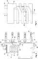
- Fig. 1 to 11 show a first embodiment of a Lucasausströmers 10th
- Fig. 1 shows a schematic representation of components of a Heilausströmers 10 in a perspective view.
- the air vent 10 has a housing 22. On the housing 10 projections 11 are arranged.
- the projections 11 have openings.
- the housing 22 with a in Fig. 1 Panel 12, not shown, are connected via connecting elements 13 of the panel 12.
- screws can be introduced into the openings of the projections 11 in order to connect the housing 22 with a diaphragm 12.
- pins or locking means can be introduced into the openings of the projections 11 to connect the housing 22 with a diaphragm 12.
- the housing may also be integrally formed with a diaphragm 12.
- the housing 22 has openings 24, the openings 24 being located both on the upper side of the housing 22 and opposite the lower side (in FIG Fig. 1 not shown) are arranged.
- the openings 24 serve to receive bearing journals 56 of lamellae 16 running in the second direction Y.
- the lamellae 16 extending in the second direction Y are therefore mounted pivotably about the bearing journals 56 in the openings 24.
- the housing 22 has openings 26.
- the openings 26 are both, as in Fig. 1 represented, arranged on the one side of the housing 22 and on the opposite side.
- bearing pins 54 are received by extending in the first direction X fins 14.
- the fins 14 are pivotally mounted in the openings 26 via the bearing pins 54.
- an electric motor 30 is arranged.
- the electric motor 30 is coupled to a first adjusting element 32.
- the first adjusting element 32 can be rotated via the electric motor 30 both clockwise and counterclockwise.
- the first adjusting element 32 has an upper surface 38, on which a second actuator 44 is arranged, which is received in a slot 50 of a second adjustment section 48.
- the first adjusting element 32 has a substantially cylindrical portion 88.
- the first adjusting element 32 is cylindrical in the first embodiment substantially over the entire length.
- a guide 36 which serves as a groove in the outer peripheral surface 34 is introduced.
- a first actuator 42 is guided.
- the first actuator 42 is connected to a displacement member 40 (in FIG Fig. 1 not shown).
- the displacement member 40 and other components are provided by an optional cover 28 in the view of FIG Fig. 1 hidden.
- Fig. 2 shows a further schematic representation of components of a Lucasausströmers 10 in a perspective view.
- the view shown represents the components of a device for pivoting fins 14 and 16 of a Heilausströmers 10 without housing 22 and aperture 12.
- the extending in the first direction X fins 14 have beab stood to the bearing pin 54 pin 62 on.
- the pins 62 are received in openings 66 of a first coupling device 18. If the first coupling device 18 is moved in the direction of the arrow 82, then a pivoting of the lamellae 14 extending in the first direction X takes place about the bearing pins 54.
- the slats 16 running in the second direction Y have pins 64 which are connected to a second coupling device 20.
- the pins 64 are arranged at a distance from the bearing pins 56, so that when the second coupling device 20 is moved in the direction of the arrow 84, the lamellae 16 extending in the second direction Y are pivoted about the bearing pins 56.
- the pins 64 of the slats 16 are received in openings 68 of the second coupling device 20.
- the first coupling device 18 has a first adjustment section 46 with a slot 50.
- a driver 58 stored in the slot 50 (see Fig. 4 ) is a driver 58 stored in the slot 50 (see Fig. 4 ) is a driver 58 stored in the slot 50 (see Fig. 4 ) is a driver 58 stored.
- the driver 58 is connected to a displacement element 40.
- the displacement element 40 has laterally guide pins 60. About the guide pins 60 and in Fig. 2 Guide rails 76, not shown, the displacement element 40 can be moved in the direction of the arrow 82.
- the first actuator 42 is further arranged. The first actuator 42 engages in the guide 36 of the first adjusting element 32nd
- the second coupling device 20 has a second adjustment section 48 with a slot 52. In the slot 52, a second actuator 44 is received.
- the second actuator 44 is arranged in the region of the peripheral edge of the upper surface 38 of the first adjusting element 32. If the first adjusting element 32 is rotated about the longitudinal axis 86 via the electric motor 30, the second actuator 44 is rotated about the longitudinal axis 86 of the first adjusting element 32 in the direction of the arrow 80. This results in a displacement of the second coupling device 20 in the direction of the arrow 84. When the first adjusting element 32 is rotated about the longitudinal axis 86 in the direction of the arrow 80, the displacing element 40 is also moved upwards or downwards in the direction of the arrow 82 by the first actuator 42 received in the guide 36.
- the guide 36 is formed substantially as a stepped helix.
- the guide 36 in this case has sections with a slope 72 and sections without slope 70 (see Fig. 5 ).
- position of the fins 14 and 16 corresponds to a neutral position, wherein the running in the first direction X fins 14 and extending in the second direction Y lamellae 16 are not pivoted from its initial position.
- the first actuator 42 is seen over the length of the guide 36 substantially in the region of the center of the guide 36. If the first adjusting element 32 is rotated in the direction of arrow 80, there is no pivoting of the extending in the first direction X fins 40, if the first actuator 42 moves along a portion 70 without inclining the guide 36.
- Fig. 3 shows a schematic representation of components of a Lucasausströmers 10 in plan view.
- the upper louver 14 extending in the first direction X is rounded at its right end, this being due to a rounded configuration of the corners of the housing 22 (see FIG Fig. 1 ) is necessary to prevent tilting of the blade 14.
- both the lamellae 14 extending in the first direction X and the lamellae 16 extending in the second direction Y are designed so that the connection to the first coupling device 18 or the second coupling device 20 by corresponding cuts in the slats 14 and 16 via Pins 62 and 64 both left and right as well as from above and below done.
- This alternative embodiment serves to prevent unwanted movements (rattling) and to keep a game as low as possible.
- Fig. 3 can be removed, carried out upon rotation of the first adjusting element 32 in the direction of arrow 80, a displacement of the second coupling device 20 in the direction of arrow 84.
- the first adjusting element 32 is connected via a drive shaft 78 to the electric motor 30. If the drive shaft 78 is rotated via the electric motor 30 in the direction of the arrow 80, the first adjustment element 32 is likewise rotated.
- the drive shaft 78 and the first adjustment element 32 are connected to one another accordingly.
- the arranged on the upper surface 38 of the first adjusting element 32 second actuator 44 is also rotated in the same direction in the direction of the arrow 80.
- the position of the displacement element 40 is above the guide pins 60 and in FIG Fig. 3 not illustrated guide rails 76 (see Fig. 7 ), wherein the displacement element 40 only in the direction of the arrow 82 (see Fig. 2 ) can be moved.
- Fig. 4 shows a further schematic representation of components of the Lucasausströmers 10 in a perspective view.
- Fig. 4 shows only the electric motor 30, the first adjusting element 32, the displacement element 40 and the first coupling device 18 and the second coupling device 20.
- the driver 58 of the displacement element 40 is received in the slot 50 of the first adjustment section 46.
- the first coupling device 18 has openings 66. In the openings 66, the pins 62 of the extending in the first direction X fins 14 are added.
- the second coupling device 20 has openings 68. In the openings 68, the pins 64 of the running in the second direction Y lamellae 16 are added.
- the driver section is connected to the displacement element 40 via an unspecified connection part.
- the optionally provided connecting part supports the driver 58, wherein a breaking or bending of the driver 58 is prevented.
- Fig. 5 shows a schematic representation of a first adjusting element 32.
- the first adjusting element 32 has at its upper surface 38, a second actuator 44 which is received in a slot 50 of a second adjustment portion 48 of a second coupling device 20.
- the first adjusting element 32 is substantially cylindrical and has a guide 36 on its outer peripheral surface 34.
- the guide 36 is formed as a stepped helix and has portions 70 without slope and sections 72 with slope. In Fig. 5 in each case only a section 70 without slope and a section 72 with slope.
- the non-pitched portions 70 extend substantially half the circumference of the first adjustment member 32. However, the non-pitched portions 70 do not extend about the entire half of the circumference of the first adjustment member 32. In preferred embodiments, each portion 70 extends without pitch and a portion 72 with slope together around half of the circumference of the first adjusting element 32.
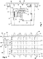
- Fig. 6 shows a schematic representation of components of a Lucasausströmers 10 in side view.
- the louvers 14 running in the first direction X and the louvers 16 extending in the second direction Y are in the neutral position of the air vent 10, wherein the louvers 14 and 16 are not deflected or pivoted.
- the first actuator 42 is located substantially in the middle of the guide 36th
- Fig. 7 shows a further schematic representation of components of a Lucasausströmers 10 in side view, wherein the housing 22 is shown with the cover 28.
- Fig. 7 further shows a guide opening 74.
- the guide opening 74 is formed as a slot.
- Guide rails 76 are arranged parallel to the guide opening 74.
- the guide pins 60 along the arrow 82 (FIG. Fig. 2 ) arranged displaceably.
- the driver 58 protrudes through the Füh approximately opening 74 therethrough.
- the housing 22 also has an opening in the region of the second coupling device 20, through which the second coupling device 20 projects at least partially out of the housing 22.
- FIG. 7 Furthermore, the connecting elements 13 of the aperture 12 are shown.
- the housing 22 is connected by the projections 11 with the diaphragm 12 and its connecting elements 13 and connecting means (eg screws).
- Fig. 9 the pins 64 of the fins 16 are pivoted to the right, wherein the first adjusting element 32 and the second actuator 44 are respectively rotated about the longitudinal axis of the first adjusting element 32 and the second actuator 44 is in a position to the right.
- the fins 16 are opposite to those in FIG Fig. 8 pivoted position shown.
- the fins 14 are in the in the Fig. 8 and 9 shown positions not pivoted because the first actuator 42 is not displaced due to the design of the guide 36 is not up or down.
- the second actuator 42 is in the positions of Fig. 8 and 9 in a section 70 with a slope equal to zero or is moved in a section 70.
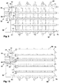
- Fig. 10 shows a state of the Lucasausströmers 10, wherein both the fins 16 and the fins 14 are pivoted.
- Fig. 11 also shows a state of the Lucasausströmers 10, wherein both the extending in the first direction X fins 14 and in the second direction Y extending lamellae 16 are pivoted.
- Fig. 10 and 11 show each extreme positions, which means that both the fins 14 and the fins 16 are in their end positions (maximum pivoting).
- the first actuator 42 has arrived at the upper end of the guide 36 and in Fig. 11 the first actuator 42 has arrived at a lower end of the guide 36.
- the drive shaft 78 and thus the first adjusting element 32 is rotated.
- the second actuator 44 is moved from a first extreme position to a second extreme position, wherein the blades 16 are pivoted either to the left or right. If the first actuator 42 is located in a section 70 without an incline, the slats 14 are not pivoted. If the first actuator 42 is located in a section 72 with an inclination or the first actuator 42 passes through a section 72 with an incline, then the slats 14 are successively pivoted upwards or downwards via the coupling of the displacing element 40, which has the first actuator 42 , in which Fig. 10 shows a state in which outflowing air is deflected downward and Fig. 11 shows a state in which outflowing air is deflected from the air vent 10 upwards.
- the electric motor 30 has terminals, not shown in the figures, which are connected to means or devices for controlling the electric motor 30.
- a touch-sensitive control panel may be arranged, which allows the control of the electric motor 30.
- the formation of the guide 36 as a stepped helix and the second actuator 44 allow a movement of the fins 14 and 16 of the air vent 10 in all positions, as in conventional Air vents are achieved.
- the air vents, as in the Fig. 1 to 11 is shown, only an electric motor 30 which is coupled to the first adjusting element 32 and the displacement element 40.
- the diameter and the height of the first adjusting element 32 are to be adapted to the design of a Heilausströmers.
- the guide 36 is adapted to an air vent and the desired Verschwenkgrade the fins of the Heilausströmers.
- the length of the sections 70 with a slope equal to zero and the length of the sections 72 are set with a slope corresponding to the desired configuration of a Heilausströmers.
- Fig. 12 to 16 show a second embodiment of a Luftausströmers 10th
- the air vent 10 of the second embodiment has a housing 22 on which projections 11 are arranged.
- the projections 11 have openings through which the housing 22 can be connected analogously to the first embodiment of a Heilausströmers 10 with a shutter, not shown, via connecting elements.
- the housing 22 also has openings 24 which are arranged on both the upper side of the housing 22 and on the lower side.
- the openings 24 serve to receive bearing journals 56 of lamellae 16 extending in the second direction Y.
- the lamellae running in the second direction Y are mounted pivotably about the bearing journals 56 in the openings 24.
- the housing 22 also has openings 26, wherein the openings 26, as in Fig. 12 represented, are arranged on the one side of the housing 22 and on the opposite side.
- bearing pins 54 are received by extending in the first direction X fins 14.
- the La mellen 14 are pivotally mounted in the openings 26 via the bearing pin 54.
- an electric motor 30 is provided in the air vent, which is coupled to a first adjusting element 32.
- the first adjusting element 32 corresponds to the first adjusting element 32 of the first embodiment.
- the first adjusting element 32 is coupled to the fins 14 extending in the first direction X as well as for the first embodiment of a Lucasausströmers 10 in the Fig. 1 to 11 is shown.
- the first adjusting element 32 has on its upper surface 38 a second actuator 44, which is arranged at a distance from the axis of rotation of the first adjusting element 32.
- the second actuator 44 is received within a slot 52 in a second adjustment section 48 of a second coupling device 20.
- the coupling device 20 extends in the first direction X along the Lucasausströmers 10.
- the second coupling device 20 has over the length of the second coupling device 20 on five openings 68, in which pins 98 are received.
- the pins 98 are arranged on the upper side 106 of second adjusting elements 90.
- the second adjusting elements 90 have a central opening 94.
- the second adjusting elements 90 are arranged rotatably on the bearing pin 96 via the central opening 94.
- the journals 96 are fixedly connected to the housing 22.
- a displacement of the second coupling device 20 therefore causes a rotation of the second adjusting elements 90 about its axis of rotation, which runs concentrically through the openings 94.
- the two th adjusting 90 at the bottom 104 each have a guide 102 (in Fig. 12 not shown), in which pins 64 are added.
- the pins 64 are spaced from the axis of rotation of the running in the second direction Y slats 16 connected to the blades 16.
- the housing 11 has openings 92 through which the pins 64 are led out of the housing 22.
- the openings 92 are formed so that a pivoting of the slats 16 is not hindered.
- the first adjusting element 32 is rotated, this causes a displacement of the second coupling device 20 and thus a rotation of the second adjusting 90.
- the extending in the second direction Y slats 16 are corresponding to Training the guide 102 pivoted.
- Fig. 13 shows a further illustration of components of the Lucasausströmers 10 of a second embodiment, wherein the housing 22 is not shown. As already stated, reference is made to the adjustment of the fins 14 running in the first direction X to the explanations relating to the first embodiment.
- Fig. 13 shows the coupling of the running in the second direction Y lamellae 16 with the second adjustment 90.
- the pins 64 of the lamellae 16 project from below into the guides 102 of the second adjustment 90. If the first adjustment member 32 about the longitudinal axis 86 in the direction of arrow 80th Twisted clockwise or counterclockwise, there is a displacement of the second coupling device 20 in the direction of arrow 84.
- a rotation of the second adjustment takes place 90 about its axis of rotation in the direction of the arrow 100.
- the rotation of the second adjusting elements 90 thereby causes pivoting of the slats 16 about their pivot axes extending through the bearing pin 56.
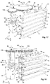
- Fig. 14 shows a view of the second adjusting elements 90 and other components of the Heilausströmers 10 of the second embodiment.
- Fig. 15 shows another schematic view of components of a Lucasausströmers 10 of the second embodiment, looking at the back of the Heilausströmers 10 in a reverse view. It should be noted that an arrangement of the components of the Heilausströmers 10 can also be done as in Fig. 15 is shown, wherein the second adjusting elements 90 are arranged on a lower side of the Heilausströmers 10.
- Fig. 15 shows the guides 102 in the second adjustment 90 at the bottom 104.
- the representation of Fig. 15 shows each almost identical guides 102, but each guide 102 may be formed differently.
- different pivot positions of the slats 16 can be achieved.
- various pivotal positions of the slats 16 are achieved at substantially the same guides 102, when the pins 64 of the slats 16 are arranged in a neutral position of the slats 16 at different positions within the guides 102.
- a displacement of the second coupling device 20 causes the pivoting of the second adjusting elements 90 by an equal amount, the lamellae 16 via the pins 64 received in the guides 102 depending on the position of the pins 64 in the guides 102 and / or the formation of the guides 102 are pivoted together by an equal amount and / or be pivoted by a different amount to each other.
- the guides 102 are formed in accordance with the guide 36, in particular the sections with slope 72 and the sections 70 without pitch, so that all positions of the slats 14 and 16 can be achieved.
- Fig. 16 shows a view of the second coupling device 20 and the bottom 104 of the second adjustment 90.
- the representation of Fig. 16 shows five second adjusting elements 90, which are formed substantially identical. Therefore, the second adjusting elements 90 substantially a gleichgeformte guide 102 in the form of a guide groove in which the pins 64 of the fins 16 are performed.
- the guides 102 are in particular designed as endless guides, so that they have no end positions.
- such second adjustment elements 90 are advantageous because no return to a neutral Position is required. For those in the Fig.
- the openings 92 and corresponding to the guides 102 must be designed so that a rotation of the second adjusting elements 90 in only one direction (clockwise or counterclockwise) is possible.
- the first adjusting element 32 must be designed so that a rotation of it in only one direction is possible. This can be achieved, for example, in that the first adjusting element 32 has a plurality of closed guide tracks, for example, analogous to the embodiment of the first adjusting element 32 of FIG Fig. 32 shown execution.
- the guides 102 are to be designed so that, as already stated above, both a common uniform pivoting of the slats 16 can take place as well as a pivoting of the slats 16 in different degrees of pivoting. As a result, spot and the diffuse positions of the fins 16 can be realized, which fan out either an exiting air flow from the air vent 10 wide or deliberately direct in a particular direction.
- the control of the fins 14 and 16 via the electric motor 30 can be carried out as described for the first embodiment.
- Fig. 17 to 21 show a third embodiment of a Lucasausströmers 10th
- the air vent 10 of the third embodiment substantially corresponds to the air vent 10 of the first and second Embodiment, however, the first adjusting element 32 is formed differently than the first adjusting elements 32 of the first and second embodiments.
- the air vent 10 of the third embodiment has a disc-shaped second adjusting element 110 in relation to the second embodiment.
- the second adjusting element 110 has a central opening 118, via which the second adjusting element 10 about a bearing pin 116 which is fixedly connected to the housing 22, is rotatable.
- the second adjusting element 110 is essentially rotatable about its longitudinal axis extending through the opening 118 in the direction of the arrow 80.
- the first adjusting element 32 has at the upper end to a gear portion 112 which is in engagement with a circumferential gear portion 114 of the second adjusting element 110. If the first adjusting element 32 is rotated about the longitudinal axis 86 in the direction of the arrow 80, the second adjusting element 110 is likewise rotated about its longitudinal axis in the direction of the arrow 80.
- the pivoting of the fins 14 extending in the first direction X takes place via the first adjusting element 32 in the same way as already described for the first embodiment, to which reference is made.
- Fig. 18 shows the components of the Lucasausströmers 10 of the third embodiment without housing 22.
- the second adjusting element 110 has on its underside (in Fig. 18 not illustrated) two guides 128 and 130, in which pin 122 of a first in the second direction Y extending lamella 16 and a second in the second direction Y extending lamella 16 are feasibly added.
- the louvers 16 extending in the second direction Y are divided into two groups, wherein the first three blades 16 are connected to each other via a second coupling rod 120.
- the coupling rod 120 has openings 132, in which pins 64 of the fins 16 are received.
- the remaining fins 16 are connected to each other via a third coupling rod 124, which also has openings 132 in which pins 64 of the fins 16 are received.
- the first blade 16 and the second blade 16 instead of a pin 64 each have a pin 122, which have a greater longitudinal extent than the pin 64.
- the pins 122 are also received in openings 132 of the second coupling rod 120 and the third coupling rod 124. If the first adjusting element 32 is rotated, a corresponding rotation of the second adjusting element 110 in the direction of the arrow 80 also takes place.
- the pins 122 are displaced via the guides 128 and 130, which leads to a pivoting of the lamellae 16.
- Fig. 19 shows a view of the back of the Heilausströmers 10 of the third embodiment.
- Fig. 19 shows the formation of the bottom 126 of the second adjusting element 110.
- This has two guides 128 and 130 which are formed substantially as endless guide tracks or guide grooves.
- the pin 122 of a blade 116 is received, which is coupled via the second coupling rod 120 with two further fins 16.
- the pin 122 of a further lamella 16 is received in the guide 128, wherein this lamella 16 is coupled via a third coupling rod 124 with two further lamellae 16.
- a pivoting of the fins 16 since the pin 122 of a first group of fins 16 in the guide 128 and the pin 122 of a second group of fins 16 are guided in a guide 130.
- the first group of louvers 16 and the second group of louvers 16 may be pivoted together by an equal amount or the first group of louvers 16 may be added to the second group of louvers 16 by a different amount pivoted.
- spot and diffuse positions of the fins 16 can be achieved.
- the guides 128 and 130 are formed depending on the guide 36 of the first adjusting element 32 so that both a common pivoting of the first group of fins 16 and the second group of fins 16 and a mutually different pivoting can take place.
- a pivoting of the slats 16 can take place when the slats 14 are not pivoted, and vice versa. Also, in each position of the slats 14, a spot and / or diffuse position of the slats 16 can be achieved.
- Fig. 20 shows a further schematic representation of the second adjusting element 110 and the blades 116 with the pin 122 and their coupling with the second coupling rod 120 and the third coupling rod 124.
- the first coupling rod 120 has three openings 132. In the first opening, the pin 122 of a control blade 16 is received.
- the control blade 16 is, like the other blades 16 pivotable about a pivot axis extending through the bearing pin 56.
- the pins 64 are also received by two further fins 16.
- a second control blade 16 is over the pin 122 connected to the third coupling rod 124, which additionally has two further openings 132, in which pins 64 are received by further fins 16.
- the pins 122 are in accordance with the formation of the guides 128 and 130 to the left or right or not pivoted.
- pivoting of the louvers 14 extending in the first direction X as well as pivoting of the louvers 16 extending in the second direction Y can take place only by turning the first adjusting element 32, with a first group of lamellae 16 being common or different from a second one Group of slats 16 can be pivoted.
- Fig. 21 shows a view of the bottom 126 of the second adjustment element 110.
- two guides 128 and 130 may also be provided a plurality of guides.
- the guides 128 and 130 are essentially designed as an endless guide track or guide groove.
- the guides 128 and 130 therefore have no end position. Therefore, embodiments are possible in which the electric motor 30 can be rotated in one direction instead of a clockwise and counterclockwise rotation.
- the control of the fins 14 and 16 via the electric motor 30 can be carried out as described for the first embodiment.
- FIGS. 22 to 27 show a fourth embodiment of a Luftausströmers 10th
- the construction of the air vent 10 of the fourth embodiment substantially corresponds to the construction of the air vent 10 of the third embodiment.
- the air vent 10 of the fourth embodiment has a second adjusting element 134 which has no guides.
- the design, arrangement and adjustment of the extending in the first direction of the fins 14 by means of the guide 36 of the first adjusting element 32 reference is made to the embodiments of the air vent 10 of the first embodiment.
- the second adjusting element 134 has a central opening 118, in which a bearing pin 116 is received.
- the journal 116 is fixedly connected to the housing 22.
- the second adjusting element 134 is rotatable about the bearing pin 116 in the direction of the arrow 80.
- two guide rails 142 are arranged on the housing 22, in which a transmission element 136 is displaceably guided in the direction of the arrow 140.
- the transmission member 136 has a rack portion 138 which is engaged with the gear portion 114 of the second adjustment member 134.
- the gear portion 114 of the second adjustment member 134 is further engaged with the gear portion 112 of the first adjustment member 132.
- the transfer member 136 is displaced in the direction of the arrow 140 along the guide rails 142 when the first adjustment member 32 about the longitudinal axis 86 in the direction of the arrow 80 is twisted.
- the rotation of the first adjusting element 32 causes a rotation of the second adjusting element 134 and via the coupling of the gear portion 114 with the rack portion 138, a displacement of the transmission element 136th
- the transmission element 136 has two guideways 144 and 146, wherein in Fig. 22 only one guideway 144 is shown. In the guideway 144 and in the guideway 146 each pin 122 of two blades 16 are feasibly added. A rotation of the first adjusting element 32 therefore also causes a pivoting of the extending in the second direction Y slats 16, wherein a first blade 16 is coupled via a second coupling rod 120 with further blades 16 and a further blade 16 via a third coupling rod 124 with again another Slats 16 is coupled.
- Fig. 23 shows essentially the same representation as Fig. 22 but are off Fig. 23 the arrangement of the guide rails 142 and the transmission element 136 can be seen better.
- the second adjusting element 134 essentially serves for transmitting the rotational movement of the first adjusting element 32. Furthermore, a translation of the rotational speed of the first adjusting element 32 via the second adjusting element 134, so that the displacement of the transmission element 136 in the direction of the arrow 140 slows down accordingly becomes. However, it can also be an acceleration depending on the translation in other unillustrated from guides.
- Fig. 24 shows a further illustration of components of the Lucasausströmers 10 of the fourth embodiment.
- Out Fig. 24 the coupling of a first group of fins 16 via a second coupling rod 120 is shown. It is also shown how pin 122 of a first lamella 16 and the pin 122 of a second lamella 16 project upwards into the guide track 144 and 146.
- the pins 122 of the slats 116 have a greater extent in the longitudinal direction than the pins 64 of the further, 16 coupled to the slats 16 slats.
- Fig. 25 shows a view of the back of components of the air vent 10 of the fourth embodiment.
- the pin 122 of a blade is received in an opening 132 of the second coupling rod 120.
- pins 64 are received by adjacent slats 16.
- the pin 122 of a further lamella 16 is received in an opening 132 of a third coupling rod 124.
- the coupling rod 124 has two further openings 132, in which pins 64 are received by two adjacent further fins 16.
- the pins 122 are also received in the guideways 144 and 146. If a rotation of the first adjusting element 32, and thus a rotation of the second adjusting element 134, takes place Moving the transmission element 136 along the guide rails 142.
- the guided in the guideways 144 and 146 pins 122 effect depending on the position of the pins 122 in the guideways 144 and 146, a pivoting of the slats. Accordingly, the lamellae of a first group can be pivoted both by an equal amount as the lamellae 16 of a second group and by a different amount.
- spot and diffuse positions can be achieved, so that the exiting air flow from the air vent 10 is either fanned out or bundled.
- Fig. 26 shows a view of the second adjusting element 134 and the transmission element 136 and two slats 16 and the second coupling rod 120 and the third coupling rod 124th
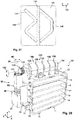
- Fig. 27 shows the view of the transmission element 136.
- the rack portion 138 is arranged on the upper side 148 of the transmission element 136 approximately centrally.
- Fig. 27 clearly shows that the guideway 144 is formed differently from the guideway 146.
- the guideways 144 and 146 have areas in which the louvers 16 of a first group of louvers 16 are pivoted together by the same amount as the louvers 16 of a second group of louvers 16. Further, the guideways 144 and 146 have areas in FIG which the lamellae 16 of a first group of lamellae 16 are pivoted differently to the lamellae 16 of a second group of lamellae 16.
- the formation of the guideways 144 and 146 is carried out in accordance with the formation of the guide 36 in the cylindrical portion 88 of the first adjusting element 32.
- the configurations of the guideways 144 and 146 and the guide 36 are chosen so that both pivoting of the fins 14 extending in the first direction X and of the fins 16 extending in the second direction Y can take place, as already indicated for the air vent 10 of the first embodiment, as well as a pivoting of the fins 16 extending in the second direction Spot and diffuse positions.
- the spot and diffuse positions as well as the positions of the lamellae 16 can be adjusted by a same amount in all positions of the lamellae 14 extending in the first direction X when pivoting together.
- the control of the fins 14 and 16 via the electric motor 30 can be carried out as described for the first embodiment.
- Fig. 28 to 31 show a fifth, not belonging to the invention, embodiment of a Lucasausströmers 10th
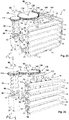
- Fig. 28 shows a perspective view of a Lucasausströmers 10 in a fifth embodiment.
- the air vent 10 has a first adjusting element 32, which is substantially completely formed from a cylindrical portion 88, at the upper end of a gear portion 162 is arranged.
- the housing 22 has on its upper side two bearings 160, via which a second adjusting element 152 is rotatably mounted.
- the second adjusting element 152 has a gear portion 154, which is in engagement with the gear portion 162 of the first adjusting element 32.
- the longitudinal axis 86 of the first adjusting element 32 extends substantially at a right angle to the longitudinal axis of the second adjusting element 152.
- the second adjusting element 152 also rotates in the direction of the arrow Arrow 164.
- the second adjusting element 152 has a cylindrical portion 156, in which five guides 158 are incorporated.
- the guides 158 are formed substantially as circumferential endless guide grooves. In these guides 158 engage pin 122, which are arranged at the fins 16 spaced from the axis of rotation passing through the bearing pin 56.
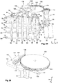
- Fig. 29 shows a further view of the Lucasausströmers 10 of the fifth embodiment without housing 22nd Fig. 29 shows that the pins 122 are spaced from the trunnions 56.
- the pins 122 project through openings in the housing 22 upwards and are guided in the guides 158. If the first adjusting element 32 is rotated, and thus a rotation of the second adjusting element 152 in the direction of the arrow 154, the lamellae 16 are pivoted in accordance with the angle of rotation and the formation of the guides 158.
- the guides 158 may each be designed differently, so that the individual blades 16 can be pivoted completely different from each other.
- the slats 16 can also be pivoted together and also spot and diffuse positions can be achieved.
- the degree of pivoting, wherein also portions may be provided which cause no pivoting of a blade 16 is only dependent on the formation of the guides 158.
- the guides 158 are formed so that in all positions of the slats 14, a pivoting of the slats 16 in all positions is possible and further spot and diffuse positions in all positions or pivotal positions of the slats 14 can be achieved.
- Fig. 30 shows a view of the back of the Lucasausströmers 10 of the fifth embodiment without housing.
- the guides 158 in Fig. 30 are formed substantially identical, but these can also be carried out otherwise.
- the formation of the second adjusting element 152 as a roller with circumferential guide grooves allows a simple way any adjustment of the fins 16. Further coupling elements and transmission elements are not necessary for this.
- Fig. 31 shows a perspective view of the second adjusting element 152.
- the second adjusting element 152 has between the cylindrical portion 156 and the gear portion 154 has a recess 166 which is mounted in a corresponding receptacle in the bearing 160. Furthermore, the second adjusting element 152 has at the lower end a portion 168, which also in a receptacle of a bearing 160th is rotatably mounted.
- the guides 148 With respect to the formation of the guides 148, reference is made to the statements made above, wherein these do not have to be formed substantially identical, as shown in the figures. Rather, the guides 158 may be formed differently to each other, so that all desired positions of the slats 16 can be achieved.
- the guides 158 also have sections with a slope and sections without slope. For sections without slope there is no pivoting of the fins 16.
- the control of the fins 14 and 16 via the electric motor 30 can be carried out as described for the first embodiment.
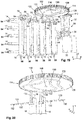
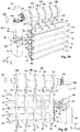
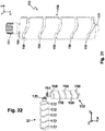
- Fig. 32 shows a further, not part of the invention, embodiment.
- Fig. 32 shows a first adjusting element 32 and a second adjusting element 152, which are formed substantially similar.
- the first adjusting element 132 has a cylindrical portion in which a plurality of guides 172 are arranged.
- the guides 172 can, unlike in Fig. 32 represented, may also be designed differently, so that coupled thereto slats 14 can be pivoted together and different from each other.
- the first adjusting element 32 also has a gear portion 170, which is coupled to the gear portion 154 of the second adjusting element 152, so that a rotation of the first adjusting element 32 or the second adjusting element 152 causes a rotation of the other adjusting element 152 or 32.
- the design of the second adjusting element 152 substantially corresponds to the fifth embodiment.
- the guides 158 may also be designed differently from one another, so that all positions of lamellae 16 are achieved can be pivoted both together by an equal amount to each other and by a mutually different amount.
- Other components are in Fig. 32 not shown, but it can be seen that further coupling elements and transmission elements are not necessary by this design.
- both in the first direction X extending lamellae 14 and in the second direction Y extending lamellae 16 are arbitrarily pivoted to each other, with only two elements (first adjusting element 32 and second adjusting element 152) are rotated relative to each other.
- the guides 158 and 172 have sections with a slope and sections without slope. For the operation of these sections, reference is made to the other embodiments.
Landscapes
- Engineering & Computer Science (AREA)
- Physics & Mathematics (AREA)
- Architecture (AREA)
- Mechanical Engineering (AREA)
- General Physics & Mathematics (AREA)
- Thermal Sciences (AREA)
- Business, Economics & Management (AREA)
- Remote Sensing (AREA)
- Civil Engineering (AREA)
- Computer Networks & Wireless Communication (AREA)
- Electromagnetism (AREA)
- Structural Engineering (AREA)
- Radar, Positioning & Navigation (AREA)
- General Health & Medical Sciences (AREA)
- Primary Health Care (AREA)
- Health & Medical Sciences (AREA)
- Economics (AREA)
- General Engineering & Computer Science (AREA)
- Human Resources & Organizations (AREA)
- Marketing (AREA)
- Chemical & Material Sciences (AREA)
- Strategic Management (AREA)
- Tourism & Hospitality (AREA)
- General Business, Economics & Management (AREA)
- Theoretical Computer Science (AREA)
- Combustion & Propulsion (AREA)
- Air-Flow Control Members (AREA)
- Blinds (AREA)
Claims (17)
- Dispositif de réglage de lamelles (14, 16) pivotantes d'un aérateur (10) agencées sensiblement perpendiculairement les unes aux autres, présentant un premier élément de réglage (32) logé de manière à pouvoir tourner, dans lequel- le premier élément de réglage (32) présente au moins une section cylindrique (88),- le premier élément de réglage (32) présente dans l'au moins une section cylindrique (88) au moins un guidage (36) permettant de guider un premier élément de déplacement (40),- au moins une lamelle (14) s'étendant dans une première direction (X) est accouplée par le biais de l'élément de déplacement (40) au premier élément de réglage (32), et- au moins une lamelle (16) s'étendant dans une seconde direction (Y) perpendiculairement à la première direction (X) est accouplée au premier élément de réglage (32),dans lequel non seulement l'au moins une lamelle (14) s'étendant dans la première direction (X) mais aussi l'au moins une lamelle (16) s'étendant dans la seconde direction (Y) peuvent pivoter par rotation du premier élément de réglage (32), caractérisé en ce que le dispositif présente au moins un deuxième élément de réglage (90 ; 110 ; 134) logé de manière à pouvoir tourner, le premier élément de réglage (32) étant accouplé à l'au moins un deuxième élément de réglage (90 ; 110 ; 134) et l'au moins un deuxième élément de réglage (90 ; 110 ; 134) étant accouplé à au moins une lamelle (16) s'étendant dans la seconde direction (Y), et l'axe de rotation du premier élément de réglage (32) s'étend parallèlement à l'axe de rotation de l'au moins un deuxième élément de réglage (90 ; 110 ; 134).
- Dispositif selon la revendication 1, dans lequel le premier élément de réglage (32) présente un second organe de réglage (44) qui est agencé parallèlement à un axe de rotation du premier élément de réglage (32), et le second organe de réglage (44) est accouplé par le biais de l'au moins un deuxième élément de réglage (90) à l'au moins une lamelle (16) s'étendant dans la seconde direction (Y).
- Dispositif selon la revendication 1 ou 2, dans lequel l'au moins un deuxième élément de réglage (90 ; 110 ; 134) est réalisé en forme de disque.
- Dispositif selon la revendication 3, dans lequel le premier élément de réglage (32) et le deuxième élément de réglage sont raccordés l'un à l'autre sans pouvoir tourner et/ou sont réalisés en tant qu'unité.
- Dispositif selon la revendication 1, 3 ou 4, dans lequel l'au moins un deuxième élément de réglage (110 ; 134) présente une section de roue dentée tournante (114) qui est en prise avec une section de roue dentée tournante (112) du premier élément de réglage (32).
- Dispositif selon la revendication 3, présentant une pluralité de seconds éléments de réglage (90), dans lequel les seconds éléments de réglage (90) présentent un guidage (102) et dans les guidages (102) un organe de réglage est reçu de manière guidable pour le pivotement de lamelles (16) s'étendant dans la seconde direction (Y), les seconds éléments de réglage (90) étant accouplés les uns aux autres et au premier élément de réglage (32).
- Dispositif selon l'une quelconque des revendications 3 à 5, dans lequel le deuxième élément de réglage (90 ; 110) présente au moins un guidage (102 ; 128 ; 130) et dans l'au moins un guidage (102 ; 128 ; 130) un organe de réglage est reçu de manière guidable pour le pivotement de l'au moins une lamelle (16) s'étendant dans la seconde direction (Y).
- Dispositif selon la revendication 5, dans lequel le deuxième élément de réglage (134) ou le premier élément de réglage est accouplé à un élément de transmission (136) et l'élément de transmission (136) présente au moins une bande de guidage (144 ; 146) dans laquelle un organe de réglage est reçu de manière guidable pour le pivotement de l'au moins une lamelle (16) s'étendant dans la seconde direction (Y), la section de roue dentée tournante (114) du deuxième élément de réglage (134) ou la section de roue dentée tournante du premier élément de réglage étant en prise avec une section de crémaillère (138) de l'élément de transmission (136).
- Dispositif selon l'une quelconque des revendications 1 à 8, dans lequel l'au moins un guidage (36) est réalisé en tant que courbe hélicoïdale.
- Dispositif selon la revendication 9, dans lequel l'au moins un guidage (36) est réalisé en tant que courbe hélicoïdale étagée, dans lequel la courbe hélicoïdale étagée présente, par rapport à la section transversale de la section cylindrique (88) du premier élément de réglage (32), des sections (70) avec une pente égale à zéro et des sections (72) avec une pente.
- Dispositif selon l'une quelconque des revendications 1 à 10, dans lequel la lamelle (14) s'étendant dans la première direction (X) est raccordée par le biais d'un premier dispositif d'accouplement (18) à d'autres lamelles (14) s'étendant dans la première direction (X) et/ou la lamelle (16) s'étendant dans la seconde direction (Y) est raccordée par le biais d'un second dispositif d'accouplement (20) à d'autres lamelles (16) s'étendant dans la seconde direction (Y).
- Dispositif selon l'une quelconque des revendications 1 à 10, dans lequel un premier groupe de lamelles (14) s'étendant dans la première direction (X) sont accouplées par le biais du premier élément de déplacement (40) au premier élément de réglage (32) et au moins un second groupe de lamelles s'étendant dans la première direction (X) sont accouplées par le biais d'un second élément de déplacement au premier élément de réglage (32) et/ou dans lequel un premier groupe de lamelles (16) s'étendant dans la seconde direction (Y) sont accouplées par le biais d'un premier système d'accouplement (120) au deuxième élément de réglage (110 ; 134) ou à l'élément de transmission (136) et au moins un second groupe de lamelles (16) s'étendant dans la seconde direction (Y) sont accouplées par le biais d'un second système d'accouplement (124) au deuxième élément de réglage (110 ; 134) ou à l'élément de transmission (136).
- Dispositif selon l'une quelconque des revendications 1 à 10 ou 11, dans lequel une pluralité de lamelles (14) s'étendant dans la première direction (X) est accouplée, par le biais de respectivement un élément de déplacement (40) séparé dans des guidages séparés dans le premier élément de réglage (32), au premier élément de réglage (32), et/ou une pluralité de lamelles (16) s'étendant dans la seconde direction (Y) est accouplée respectivement, avec un deuxième élément de réglage (90) séparé ou respectivement dans une bande de guidage (144 ; 146) séparée prévue dans l'élément de transmission (136), à l'élément de transmission (136).
- Dispositif selon l'une quelconque des revendications 1 à 13, dans lequel le premier élément de réglage (32) ou le deuxième élément de réglage (90 ; 110 ; 134) est accouplé à un arbre d'entraînement (78) et/ou à un moteur électrique (30) ou à une roue de réglage et/ou le moteur électrique (30) est raccordé électriquement aux moyens de réglage de la vitesse de rotation par le biais de systèmes de saisie ou l'arbre d'entraînement peut être commandé par le biais de systèmes mécaniques.
- Dispositif selon l'une quelconque des revendications 1 à 14, dans lequel le premier élément de réglage (32) ou le deuxième élément de réglage (90 ; 110 ; 134) est accouplé à un troisième élément de réglage et le troisième élément de réglage est accouplé à un système pour l'ouverture et la fermeture de l'amenée d'air à l'aérateur (10).
- Dispositif selon l'une quelconque des revendications 1 à 14, dans lequel le premier élément de réglage (32) ou le deuxième élément de réglage (90 ; 110 ; 134) est accouplé à un système pour l'ouverture et la fermeture de l'amenée d'air.
- Dispositif selon la revendication 15 ou 16, dans lequel le premier élément de réglage (32), le deuxième élément de réglage (90 ; 110 ; 134) ou le troisième élément de réglage présentent un guidage permettant de guider un organe de réglage pour l'ouverture et la fermeture du système.
Priority Applications (1)
| Application Number | Priority Date | Filing Date | Title |
|---|---|---|---|
| EP16198255.8A EP3192684B1 (fr) | 2014-04-14 | 2015-03-19 | Dispositif de déplacement de lamelles d'un diffuseur d'air |
Applications Claiming Priority (2)
| Application Number | Priority Date | Filing Date | Title |
|---|---|---|---|
| DE102014105273.0A DE102014105273B3 (de) | 2014-04-14 | 2014-04-14 | Einrichtung zum Verstellen von Lamellen eines Luftausströmers |
| PCT/EP2015/055776 WO2015158486A2 (fr) | 2014-04-14 | 2015-03-19 | Dispositif de réglage de lames pivotantes d'un aérateur |
Related Child Applications (2)
| Application Number | Title | Priority Date | Filing Date |
|---|---|---|---|
| EP16198255.8A Division EP3192684B1 (fr) | 2014-04-14 | 2015-03-19 | Dispositif de déplacement de lamelles d'un diffuseur d'air |
| EP16198255.8A Division-Into EP3192684B1 (fr) | 2014-04-14 | 2015-03-19 | Dispositif de déplacement de lamelles d'un diffuseur d'air |
Publications (2)
| Publication Number | Publication Date |
|---|---|
| EP3131774A2 EP3131774A2 (fr) | 2017-02-22 |
| EP3131774B1 true EP3131774B1 (fr) | 2019-07-17 |
Family
ID=52814067
Family Applications (2)
| Application Number | Title | Priority Date | Filing Date |
|---|---|---|---|
| EP16198255.8A Active EP3192684B1 (fr) | 2014-04-14 | 2015-03-19 | Dispositif de déplacement de lamelles d'un diffuseur d'air |
| EP15712577.4A Active EP3131774B1 (fr) | 2014-04-14 | 2015-03-19 | Dispositif de réglage de lames pivotantes d'un aérateur |
Family Applications Before (1)
| Application Number | Title | Priority Date | Filing Date |
|---|---|---|---|
| EP16198255.8A Active EP3192684B1 (fr) | 2014-04-14 | 2015-03-19 | Dispositif de déplacement de lamelles d'un diffuseur d'air |
Country Status (3)
| Country | Link |
|---|---|
| EP (2) | EP3192684B1 (fr) |
| DE (2) | DE202014010325U1 (fr) |
| WO (1) | WO2015158486A2 (fr) |
Cited By (1)
| Publication number | Priority date | Publication date | Assignee | Title |
|---|---|---|---|---|
| CN112706588A (zh) * | 2021-03-26 | 2021-04-27 | 宁波均胜群英汽车系统股份有限公司 | 一种汽车空调出风口 |
Families Citing this family (15)
| Publication number | Priority date | Publication date | Assignee | Title |
|---|---|---|---|---|
| DE102016118792A1 (de) * | 2016-10-05 | 2018-04-05 | Dr. Ing. H.C. F. Porsche Aktiengesellschaft | Luftauslass für ein Belüftungssystem eines Kraftfahrzeugs |
| CN106765602B (zh) * | 2017-01-20 | 2023-04-07 | 美的集团武汉制冷设备有限公司 | 空调室内机及其导风组件 |
| CN107014052B (zh) * | 2017-04-11 | 2020-04-24 | 青岛海尔空调器有限总公司 | 一种摆风机构及空调器 |
| CN108128121A (zh) * | 2018-02-06 | 2018-06-08 | 浙江智动汽车部件有限公司 | 一种风向调节装置 |
| DE102018005002B4 (de) * | 2018-06-22 | 2022-06-09 | Mercedes-Benz Group AG | Luftausströmer für einen Kraftwagen, insbesondere für einen Personenkraftwagen |
| JP7258642B2 (ja) * | 2019-04-26 | 2023-04-17 | 東芝キヤリア株式会社 | 風向調整装置、および空気調和機の室内ユニット |
| DE102020114181A1 (de) * | 2019-06-26 | 2020-12-31 | Fischer Automotive Systems Gmbh & Co. Kg | Belüftungsvorrichtung für einen Automobilinnenraum |
| CN113266941B (zh) * | 2021-06-18 | 2024-11-26 | 珠海格力电器股份有限公司 | 导风板组件和空气调节设备 |
| DE102022120448A1 (de) * | 2022-08-12 | 2024-02-15 | Bayerische Motoren Werke Aktiengesellschaft | Elektrisch verstellbarer Luftausströmer für ein Kraftfahrzeug, Verfahren zum Betreiben eines solchen Luftausströmers sowie hiermit ausgestattetes Kraftfahrzeug |
| FR3144058B1 (fr) * | 2022-12-22 | 2024-12-13 | Novares France | Aérateur pour habitacle de véhicule automobile |
| DE102023103895A1 (de) * | 2023-02-16 | 2024-08-22 | Weber Gmbh & Co. Kg Kunststofftechnik Und Formenbau | Luftausströmer mit einstellbarer Luftaustrittsrichtung |
| DE102023110934B3 (de) | 2023-04-27 | 2024-05-29 | Grammer Aktiengesellschaft | Kinematisches Bauteil |
| CN117267801A (zh) * | 2023-10-07 | 2023-12-22 | 惠州雷士光电科技有限公司 | 一种出风面板、出风装置及出风控制方法 |
| DE102024113417A1 (de) * | 2024-05-14 | 2025-11-20 | Grammer Aktiengesellschaft | Luftausströmer |
| DE102024113414A1 (de) * | 2024-05-14 | 2025-11-20 | Grammer Aktiengesellschaft | Luftausströmer für ein Fahrzeug |
Family Cites Families (19)
| Publication number | Priority date | Publication date | Assignee | Title |
|---|---|---|---|---|
| JPS57188038U (fr) * | 1981-05-26 | 1982-11-29 | ||
| DE3628449A1 (de) * | 1986-08-21 | 1988-02-25 | Happich Gmbh Gebr | Luftleitvorrichtung |
| JPH01142359A (ja) * | 1987-11-27 | 1989-06-05 | Matsushita Seiko Co Ltd | 風向変更装置 |
| JPH01125959U (fr) * | 1988-02-19 | 1989-08-28 | ||
| DE4327265C2 (de) * | 1993-08-13 | 1995-10-26 | Daimler Benz Ag | Luftdüse |
| JPH0952519A (ja) * | 1995-08-11 | 1997-02-25 | Toyoda Gosei Co Ltd | 車両用送風方向調整装置 |
| KR100210085B1 (ko) * | 1996-03-21 | 1999-07-15 | 윤종용 | 공기조화기의 풍향조절장치 |
| JPH10232047A (ja) * | 1997-02-20 | 1998-09-02 | Fujitsu General Ltd | 空気調和機の風向調節装置 |
| JP4281179B2 (ja) | 1998-11-25 | 2009-06-17 | 株式会社デンソー | 車両用空調装置 |
| DE19943822B4 (de) * | 1999-09-14 | 2008-11-27 | Behr Gmbh & Co. Kg | Strömungsleitanordnung, insbesondere Ausströmgrill für Lüftungs- und Klimaanlagen von Kraftfahrzeugen |
| DE10231580B4 (de) * | 2002-07-11 | 2007-06-14 | Olho-Technik Oleff & Holtmann Ohg | In die Armaturentafel eines Kraftfahrzeuges einbaubare Lüftungsdüse |
| FR2844484B1 (fr) * | 2002-09-13 | 2006-01-20 | Bourbon Automobile Sa | Aerateur, notamment pour habitacle de vehicule automobile |
| US6830511B2 (en) * | 2003-01-21 | 2004-12-14 | Collins & Aikman Products Co. | Air duct outlets with remotely-located joystick louver controls |
| JP3988081B2 (ja) * | 2003-06-12 | 2007-10-10 | 豊田合成株式会社 | 風向調整装置 |
| FR2861652B1 (fr) * | 2003-10-29 | 2006-01-06 | Peugeot Citroen Automobiles Sa | Dispositif de l'orientation des ailettes ou volets deflecteurs d'air d'un vehicule automobile |
| US7455581B2 (en) * | 2004-09-24 | 2008-11-25 | Johnson Controls, Inc. | Air duct outlets with remotely-located joystick louver controls |
| DE102005037748B3 (de) * | 2005-08-10 | 2007-02-08 | Dr. Schneider Engineering Gmbh | Luftdüse |
| JP2007152974A (ja) * | 2005-11-30 | 2007-06-21 | Kojima Press Co Ltd | 車両用空気吹出口装置 |
| DE102007035507A1 (de) * | 2007-07-28 | 2009-01-29 | Bayerische Motoren Werke Aktiengesellschaft | Kraftfahrzeug-Belüftungseinrichtung |
-
2014
- 2014-04-14 DE DE202014010325.9U patent/DE202014010325U1/de not_active Expired - Lifetime
- 2014-04-14 DE DE102014105273.0A patent/DE102014105273B3/de not_active Expired - Fee Related
-
2015
- 2015-03-19 EP EP16198255.8A patent/EP3192684B1/fr active Active
- 2015-03-19 EP EP15712577.4A patent/EP3131774B1/fr active Active
- 2015-03-19 WO PCT/EP2015/055776 patent/WO2015158486A2/fr not_active Ceased
Non-Patent Citations (1)
| Title |
|---|
| None * |
Cited By (2)
| Publication number | Priority date | Publication date | Assignee | Title |
|---|---|---|---|---|
| CN112706588A (zh) * | 2021-03-26 | 2021-04-27 | 宁波均胜群英汽车系统股份有限公司 | 一种汽车空调出风口 |
| CN112706588B (zh) * | 2021-03-26 | 2021-06-18 | 宁波均胜群英汽车系统股份有限公司 | 一种汽车空调出风口 |
Also Published As
| Publication number | Publication date |
|---|---|
| DE102014105273B3 (de) | 2015-06-18 |
| EP3192684A1 (fr) | 2017-07-19 |
| DE202014010325U1 (de) | 2015-08-07 |
| EP3192684B1 (fr) | 2019-10-02 |
| WO2015158486A2 (fr) | 2015-10-22 |
| EP3131774A2 (fr) | 2017-02-22 |
| WO2015158486A3 (fr) | 2015-12-17 |
Similar Documents
| Publication | Publication Date | Title |
|---|---|---|
| EP3131774B1 (fr) | Dispositif de réglage de lames pivotantes d'un aérateur | |
| EP0888916B1 (fr) | Système avec lamelles pour dispositifs d'aération pour régler la ventilation, notamment pour l'aération de véhicules à moteur | |
| EP3303032B1 (fr) | Diffuseur d'air comprenant un dispositif de commande | |
| DE102015101101B3 (de) | Antriebseinrichtung zum Verstellen mindestens zweier Vorrichtungen | |
| DE102015101254B3 (de) | Antriebseinrichtung zum Verstellen mindestens zweier Vorrichtungen | |
| EP3530506B1 (fr) | Dispositif d'écoulement d'air | |
| DE69707755T2 (de) | Temperatursteuerung für Fahrzeuge | |
| DE102012015519A1 (de) | Luftleitvorrichtung für eine Luftausströmvorrichtung eines Fahrzeugs | |
| EP2243647B1 (fr) | Aérateur destiné à l'utilisation dans des véhicules automobiles | |
| DE102005061722A1 (de) | Luftausströmer mit Drallströmung | |
| WO2011029683A1 (fr) | Buse d'air arquée | |
| EP1270286B1 (fr) | Dispositif pour diriger l'air, notamment pour un véhicule | |
| DE102019132921B4 (de) | Luftausströmer mit Bedieneinrichtung | |
| DE102021111535A1 (de) | Luftausströmeranordnung | |
| DE202005012570U1 (de) | Luftdüse | |
| DE102015112571B3 (de) | Belüftungseinrichtung | |
| EP3921195A1 (fr) | Dispositif de commande pour un élément de guidage d'air monté monté pivotant | |
| EP3328670B1 (fr) | Dispositif de ventilation | |
| DE102017128105B4 (de) | Luftausströmer | |
| DE19816013B4 (de) | Luftstromverteiler für einen Kraftfahrzeuginnenraum | |
| DE102019121738A1 (de) | Bedieneinrichtung für ein verschwenkbar gelagertes Luftleitelement und Luftausströmer mit Bedieneinrichtung | |
| DE102004027914A1 (de) | Verschluss für mindestens eine Öffnung | |
| DE102023103899B4 (de) | Luftausströmer mit einstellbarer Luftaustrittsrichtung | |
| DE102005037748B3 (de) | Luftdüse | |
| EP3553626B1 (fr) | Dispositif de commande |
Legal Events
| Date | Code | Title | Description |
|---|---|---|---|
| STAA | Information on the status of an ep patent application or granted ep patent |
Free format text: STATUS: THE INTERNATIONAL PUBLICATION HAS BEEN MADE |
|
| PUAI | Public reference made under article 153(3) epc to a published international application that has entered the european phase |
Free format text: ORIGINAL CODE: 0009012 |
|
| STAA | Information on the status of an ep patent application or granted ep patent |
Free format text: STATUS: REQUEST FOR EXAMINATION WAS MADE |
|
| 17P | Request for examination filed |
Effective date: 20161110 |
|
| AK | Designated contracting states |
Kind code of ref document: A2 Designated state(s): AL AT BE BG CH CY CZ DE DK EE ES FI FR GB GR HR HU IE IS IT LI LT LU LV MC MK MT NL NO PL PT RO RS SE SI SK SM TR |
|
| AX | Request for extension of the european patent |
Extension state: BA ME |
|
| DAV | Request for validation of the european patent (deleted) | ||
| DAX | Request for extension of the european patent (deleted) | ||
| GRAP | Despatch of communication of intention to grant a patent |
Free format text: ORIGINAL CODE: EPIDOSNIGR1 |
|
| STAA | Information on the status of an ep patent application or granted ep patent |
Free format text: STATUS: GRANT OF PATENT IS INTENDED |
|
| INTG | Intention to grant announced |
Effective date: 20190219 |
|
| GRAS | Grant fee paid |
Free format text: ORIGINAL CODE: EPIDOSNIGR3 |
|
| GRAA | (expected) grant |
Free format text: ORIGINAL CODE: 0009210 |
|
| STAA | Information on the status of an ep patent application or granted ep patent |
Free format text: STATUS: THE PATENT HAS BEEN GRANTED |
|
| AK | Designated contracting states |
Kind code of ref document: B1 Designated state(s): AL AT BE BG CH CY CZ DE DK EE ES FI FR GB GR HR HU IE IS IT LI LT LU LV MC MK MT NL NO PL PT RO RS SE SI SK SM TR |
|
| REG | Reference to a national code |
Ref country code: GB Ref legal event code: FG4D Free format text: NOT ENGLISH |
|
| REG | Reference to a national code |
Ref country code: CH Ref legal event code: EP |
|
| REG | Reference to a national code |
Ref country code: IE Ref legal event code: FG4D Free format text: LANGUAGE OF EP DOCUMENT: GERMAN |
|
| REG | Reference to a national code |
Ref country code: DE Ref legal event code: R096 Ref document number: 502015009664 Country of ref document: DE |
|
| REG | Reference to a national code |
Ref country code: AT Ref legal event code: REF Ref document number: 1155515 Country of ref document: AT Kind code of ref document: T Effective date: 20190815 |
|
| REG | Reference to a national code |
Ref country code: NL Ref legal event code: MP Effective date: 20190717 |
|
| REG | Reference to a national code |
Ref country code: LT Ref legal event code: MG4D |
|
| PG25 | Lapsed in a contracting state [announced via postgrant information from national office to epo] |
Ref country code: BG Free format text: LAPSE BECAUSE OF FAILURE TO SUBMIT A TRANSLATION OF THE DESCRIPTION OR TO PAY THE FEE WITHIN THE PRESCRIBED TIME-LIMIT Effective date: 20191017 Ref country code: SE Free format text: LAPSE BECAUSE OF FAILURE TO SUBMIT A TRANSLATION OF THE DESCRIPTION OR TO PAY THE FEE WITHIN THE PRESCRIBED TIME-LIMIT Effective date: 20190717 Ref country code: NL Free format text: LAPSE BECAUSE OF FAILURE TO SUBMIT A TRANSLATION OF THE DESCRIPTION OR TO PAY THE FEE WITHIN THE PRESCRIBED TIME-LIMIT Effective date: 20190717 Ref country code: NO Free format text: LAPSE BECAUSE OF FAILURE TO SUBMIT A TRANSLATION OF THE DESCRIPTION OR TO PAY THE FEE WITHIN THE PRESCRIBED TIME-LIMIT Effective date: 20191017 Ref country code: FI Free format text: LAPSE BECAUSE OF FAILURE TO SUBMIT A TRANSLATION OF THE DESCRIPTION OR TO PAY THE FEE WITHIN THE PRESCRIBED TIME-LIMIT Effective date: 20190717 Ref country code: PT Free format text: LAPSE BECAUSE OF FAILURE TO SUBMIT A TRANSLATION OF THE DESCRIPTION OR TO PAY THE FEE WITHIN THE PRESCRIBED TIME-LIMIT Effective date: 20191118 Ref country code: HR Free format text: LAPSE BECAUSE OF FAILURE TO SUBMIT A TRANSLATION OF THE DESCRIPTION OR TO PAY THE FEE WITHIN THE PRESCRIBED TIME-LIMIT Effective date: 20190717 Ref country code: LT Free format text: LAPSE BECAUSE OF FAILURE TO SUBMIT A TRANSLATION OF THE DESCRIPTION OR TO PAY THE FEE WITHIN THE PRESCRIBED TIME-LIMIT Effective date: 20190717 |
|
| PG25 | Lapsed in a contracting state [announced via postgrant information from national office to epo] |
Ref country code: AL Free format text: LAPSE BECAUSE OF FAILURE TO SUBMIT A TRANSLATION OF THE DESCRIPTION OR TO PAY THE FEE WITHIN THE PRESCRIBED TIME-LIMIT Effective date: 20190717 Ref country code: RS Free format text: LAPSE BECAUSE OF FAILURE TO SUBMIT A TRANSLATION OF THE DESCRIPTION OR TO PAY THE FEE WITHIN THE PRESCRIBED TIME-LIMIT Effective date: 20190717 Ref country code: IS Free format text: LAPSE BECAUSE OF FAILURE TO SUBMIT A TRANSLATION OF THE DESCRIPTION OR TO PAY THE FEE WITHIN THE PRESCRIBED TIME-LIMIT Effective date: 20191117 Ref country code: LV Free format text: LAPSE BECAUSE OF FAILURE TO SUBMIT A TRANSLATION OF THE DESCRIPTION OR TO PAY THE FEE WITHIN THE PRESCRIBED TIME-LIMIT Effective date: 20190717 Ref country code: GR Free format text: LAPSE BECAUSE OF FAILURE TO SUBMIT A TRANSLATION OF THE DESCRIPTION OR TO PAY THE FEE WITHIN THE PRESCRIBED TIME-LIMIT Effective date: 20191018 Ref country code: ES Free format text: LAPSE BECAUSE OF FAILURE TO SUBMIT A TRANSLATION OF THE DESCRIPTION OR TO PAY THE FEE WITHIN THE PRESCRIBED TIME-LIMIT Effective date: 20190717 |
|
| PG25 | Lapsed in a contracting state [announced via postgrant information from national office to epo] |
Ref country code: TR Free format text: LAPSE BECAUSE OF FAILURE TO SUBMIT A TRANSLATION OF THE DESCRIPTION OR TO PAY THE FEE WITHIN THE PRESCRIBED TIME-LIMIT Effective date: 20190717 |
|
| PG25 | Lapsed in a contracting state [announced via postgrant information from national office to epo] |
Ref country code: PL Free format text: LAPSE BECAUSE OF FAILURE TO SUBMIT A TRANSLATION OF THE DESCRIPTION OR TO PAY THE FEE WITHIN THE PRESCRIBED TIME-LIMIT Effective date: 20190717 Ref country code: EE Free format text: LAPSE BECAUSE OF FAILURE TO SUBMIT A TRANSLATION OF THE DESCRIPTION OR TO PAY THE FEE WITHIN THE PRESCRIBED TIME-LIMIT Effective date: 20190717 Ref country code: DK Free format text: LAPSE BECAUSE OF FAILURE TO SUBMIT A TRANSLATION OF THE DESCRIPTION OR TO PAY THE FEE WITHIN THE PRESCRIBED TIME-LIMIT Effective date: 20190717 Ref country code: RO Free format text: LAPSE BECAUSE OF FAILURE TO SUBMIT A TRANSLATION OF THE DESCRIPTION OR TO PAY THE FEE WITHIN THE PRESCRIBED TIME-LIMIT Effective date: 20190717 Ref country code: IT Free format text: LAPSE BECAUSE OF FAILURE TO SUBMIT A TRANSLATION OF THE DESCRIPTION OR TO PAY THE FEE WITHIN THE PRESCRIBED TIME-LIMIT Effective date: 20190717 |
|
| PG25 | Lapsed in a contracting state [announced via postgrant information from national office to epo] |
Ref country code: CZ Free format text: LAPSE BECAUSE OF FAILURE TO SUBMIT A TRANSLATION OF THE DESCRIPTION OR TO PAY THE FEE WITHIN THE PRESCRIBED TIME-LIMIT Effective date: 20190717 Ref country code: SK Free format text: LAPSE BECAUSE OF FAILURE TO SUBMIT A TRANSLATION OF THE DESCRIPTION OR TO PAY THE FEE WITHIN THE PRESCRIBED TIME-LIMIT Effective date: 20190717 Ref country code: SM Free format text: LAPSE BECAUSE OF FAILURE TO SUBMIT A TRANSLATION OF THE DESCRIPTION OR TO PAY THE FEE WITHIN THE PRESCRIBED TIME-LIMIT Effective date: 20190717 Ref country code: IS Free format text: LAPSE BECAUSE OF FAILURE TO SUBMIT A TRANSLATION OF THE DESCRIPTION OR TO PAY THE FEE WITHIN THE PRESCRIBED TIME-LIMIT Effective date: 20200224 |
|
| REG | Reference to a national code |
Ref country code: DE Ref legal event code: R097 Ref document number: 502015009664 Country of ref document: DE |
|
| PLBE | No opposition filed within time limit |
Free format text: ORIGINAL CODE: 0009261 |
|
| STAA | Information on the status of an ep patent application or granted ep patent |
Free format text: STATUS: NO OPPOSITION FILED WITHIN TIME LIMIT |
|
| PG2D | Information on lapse in contracting state deleted |
Ref country code: IS |
|
| 26N | No opposition filed |
Effective date: 20200603 |
|
| PG25 | Lapsed in a contracting state [announced via postgrant information from national office to epo] |
Ref country code: SI Free format text: LAPSE BECAUSE OF FAILURE TO SUBMIT A TRANSLATION OF THE DESCRIPTION OR TO PAY THE FEE WITHIN THE PRESCRIBED TIME-LIMIT Effective date: 20190717 |
|
| PG25 | Lapsed in a contracting state [announced via postgrant information from national office to epo] |
Ref country code: MC Free format text: LAPSE BECAUSE OF FAILURE TO SUBMIT A TRANSLATION OF THE DESCRIPTION OR TO PAY THE FEE WITHIN THE PRESCRIBED TIME-LIMIT Effective date: 20190717 |
|
| REG | Reference to a national code |
Ref country code: CH Ref legal event code: PL |
|
| REG | Reference to a national code |
Ref country code: BE Ref legal event code: MM Effective date: 20200331 |
|
| PG25 | Lapsed in a contracting state [announced via postgrant information from national office to epo] |
Ref country code: LU Free format text: LAPSE BECAUSE OF NON-PAYMENT OF DUE FEES Effective date: 20200319 |
|
| PG25 | Lapsed in a contracting state [announced via postgrant information from national office to epo] |
Ref country code: IE Free format text: LAPSE BECAUSE OF NON-PAYMENT OF DUE FEES Effective date: 20200319 Ref country code: FR Free format text: LAPSE BECAUSE OF NON-PAYMENT OF DUE FEES Effective date: 20200331 Ref country code: LI Free format text: LAPSE BECAUSE OF NON-PAYMENT OF DUE FEES Effective date: 20200331 Ref country code: CH Free format text: LAPSE BECAUSE OF NON-PAYMENT OF DUE FEES Effective date: 20200331 |
|
| PG25 | Lapsed in a contracting state [announced via postgrant information from national office to epo] |
Ref country code: BE Free format text: LAPSE BECAUSE OF NON-PAYMENT OF DUE FEES Effective date: 20200331 |
|
| GBPC | Gb: european patent ceased through non-payment of renewal fee |
Effective date: 20200319 |
|
| PG25 | Lapsed in a contracting state [announced via postgrant information from national office to epo] |
Ref country code: GB Free format text: LAPSE BECAUSE OF NON-PAYMENT OF DUE FEES Effective date: 20200319 |
|
| REG | Reference to a national code |
Ref country code: AT Ref legal event code: MM01 Ref document number: 1155515 Country of ref document: AT Kind code of ref document: T Effective date: 20200319 |
|
| PG25 | Lapsed in a contracting state [announced via postgrant information from national office to epo] |
Ref country code: AT Free format text: LAPSE BECAUSE OF NON-PAYMENT OF DUE FEES Effective date: 20200319 |
|
| PG25 | Lapsed in a contracting state [announced via postgrant information from national office to epo] |
Ref country code: MT Free format text: LAPSE BECAUSE OF FAILURE TO SUBMIT A TRANSLATION OF THE DESCRIPTION OR TO PAY THE FEE WITHIN THE PRESCRIBED TIME-LIMIT Effective date: 20190717 Ref country code: CY Free format text: LAPSE BECAUSE OF FAILURE TO SUBMIT A TRANSLATION OF THE DESCRIPTION OR TO PAY THE FEE WITHIN THE PRESCRIBED TIME-LIMIT Effective date: 20190717 |
|
| PG25 | Lapsed in a contracting state [announced via postgrant information from national office to epo] |
Ref country code: MK Free format text: LAPSE BECAUSE OF FAILURE TO SUBMIT A TRANSLATION OF THE DESCRIPTION OR TO PAY THE FEE WITHIN THE PRESCRIBED TIME-LIMIT Effective date: 20190717 |
|
| P01 | Opt-out of the competence of the unified patent court (upc) registered |
Effective date: 20230525 |
|
| PGFP | Annual fee paid to national office [announced via postgrant information from national office to epo] |
Ref country code: DE Payment date: 20250226 Year of fee payment: 11 |
|
| REG | Reference to a national code |
Ref country code: DE Ref legal event code: R081 Ref document number: 502015009664 Country of ref document: DE Owner name: MOTHERSON DRSC DEUTSCHLAND GMBH, DE Free format text: FORMER OWNER: DR. SCHNEIDER KUNSTSTOFFWERKE GMBH, 96317 KRONACH, DE |