EP3132123B1 - Kraftstoffgetriebepumpe zur verwendung, im besonderen, als hochdruckpumpe - Google Patents
Kraftstoffgetriebepumpe zur verwendung, im besonderen, als hochdruckpumpe Download PDFInfo
- Publication number
- EP3132123B1 EP3132123B1 EP15720387.8A EP15720387A EP3132123B1 EP 3132123 B1 EP3132123 B1 EP 3132123B1 EP 15720387 A EP15720387 A EP 15720387A EP 3132123 B1 EP3132123 B1 EP 3132123B1
- Authority
- EP
- European Patent Office
- Prior art keywords
- pump
- bearings
- fluid
- pinions
- gear pump
- Prior art date
- Legal status (The legal status is an assumption and is not a legal conclusion. Google has not performed a legal analysis and makes no representation as to the accuracy of the status listed.)
- Active
Links
Images



Classifications
-
- F—MECHANICAL ENGINEERING; LIGHTING; HEATING; WEAPONS; BLASTING
- F02—COMBUSTION ENGINES; HOT-GAS OR COMBUSTION-PRODUCT ENGINE PLANTS
- F02C—GAS-TURBINE PLANTS; AIR INTAKES FOR JET-PROPULSION PLANTS; CONTROLLING FUEL SUPPLY IN AIR-BREATHING JET-PROPULSION PLANTS
- F02C7/00—Features, components parts, details or accessories, not provided for in, or of interest apart form groups F02C1/00 - F02C6/00; Air intakes for jet-propulsion plants
- F02C7/22—Fuel supply systems
- F02C7/236—Fuel delivery systems comprising two or more pumps
-
- F—MECHANICAL ENGINEERING; LIGHTING; HEATING; WEAPONS; BLASTING
- F01—MACHINES OR ENGINES IN GENERAL; ENGINE PLANTS IN GENERAL; STEAM ENGINES
- F01D—NON-POSITIVE DISPLACEMENT MACHINES OR ENGINES, e.g. STEAM TURBINES
- F01D25/00—Component parts, details, or accessories, not provided for in, or of interest apart from, other groups
- F01D25/18—Lubricating arrangements
- F01D25/183—Sealing means
- F01D25/186—Sealing means for sliding contact bearing
-
- F—MECHANICAL ENGINEERING; LIGHTING; HEATING; WEAPONS; BLASTING
- F04—POSITIVE - DISPLACEMENT MACHINES FOR LIQUIDS; PUMPS FOR LIQUIDS OR ELASTIC FLUIDS
- F04C—ROTARY-PISTON, OR OSCILLATING-PISTON, POSITIVE-DISPLACEMENT MACHINES FOR LIQUIDS; ROTARY-PISTON, OR OSCILLATING-PISTON, POSITIVE-DISPLACEMENT PUMPS
- F04C11/00—Combinations of two or more machines or pumps, each being of rotary-piston or oscillating-piston type; Pumping installations
- F04C11/001—Combinations of two or more machines or pumps, each being of rotary-piston or oscillating-piston type; Pumping installations of similar working principle
-
- F—MECHANICAL ENGINEERING; LIGHTING; HEATING; WEAPONS; BLASTING
- F04—POSITIVE - DISPLACEMENT MACHINES FOR LIQUIDS; PUMPS FOR LIQUIDS OR ELASTIC FLUIDS
- F04C—ROTARY-PISTON, OR OSCILLATING-PISTON, POSITIVE-DISPLACEMENT MACHINES FOR LIQUIDS; ROTARY-PISTON, OR OSCILLATING-PISTON, POSITIVE-DISPLACEMENT PUMPS
- F04C11/00—Combinations of two or more machines or pumps, each being of rotary-piston or oscillating-piston type; Pumping installations
- F04C11/005—Combinations of two or more machines or pumps, each being of rotary-piston or oscillating-piston type; Pumping installations of dissimilar working principle
-
- F—MECHANICAL ENGINEERING; LIGHTING; HEATING; WEAPONS; BLASTING
- F04—POSITIVE - DISPLACEMENT MACHINES FOR LIQUIDS; PUMPS FOR LIQUIDS OR ELASTIC FLUIDS
- F04C—ROTARY-PISTON, OR OSCILLATING-PISTON, POSITIVE-DISPLACEMENT MACHINES FOR LIQUIDS; ROTARY-PISTON, OR OSCILLATING-PISTON, POSITIVE-DISPLACEMENT PUMPS
- F04C15/00—Component parts, details or accessories of machines, pumps or pumping installations, not provided for in groups F04C2/00 - F04C14/00
- F04C15/0003—Sealing arrangements in rotary-piston machines or pumps
- F04C15/0034—Sealing arrangements in rotary-piston machines or pumps for other than the working fluid, i.e. the sealing arrangements are not between working chambers of the machine
- F04C15/0038—Shaft sealings specially adapted for rotary-piston machines or pumps
-
- F—MECHANICAL ENGINEERING; LIGHTING; HEATING; WEAPONS; BLASTING
- F04—POSITIVE - DISPLACEMENT MACHINES FOR LIQUIDS; PUMPS FOR LIQUIDS OR ELASTIC FLUIDS
- F04C—ROTARY-PISTON, OR OSCILLATING-PISTON, POSITIVE-DISPLACEMENT MACHINES FOR LIQUIDS; ROTARY-PISTON, OR OSCILLATING-PISTON, POSITIVE-DISPLACEMENT PUMPS
- F04C2/00—Rotary-piston machines or pumps
- F04C2/08—Rotary-piston machines or pumps of intermeshing-engagement type, i.e. with engagement of co-operating members similar to that of toothed gearing
-
- F—MECHANICAL ENGINEERING; LIGHTING; HEATING; WEAPONS; BLASTING
- F04—POSITIVE - DISPLACEMENT MACHINES FOR LIQUIDS; PUMPS FOR LIQUIDS OR ELASTIC FLUIDS
- F04C—ROTARY-PISTON, OR OSCILLATING-PISTON, POSITIVE-DISPLACEMENT MACHINES FOR LIQUIDS; ROTARY-PISTON, OR OSCILLATING-PISTON, POSITIVE-DISPLACEMENT PUMPS
- F04C2/00—Rotary-piston machines or pumps
- F04C2/08—Rotary-piston machines or pumps of intermeshing-engagement type, i.e. with engagement of co-operating members similar to that of toothed gearing
- F04C2/12—Rotary-piston machines or pumps of intermeshing-engagement type, i.e. with engagement of co-operating members similar to that of toothed gearing of other than internal-axis type
- F04C2/14—Rotary-piston machines or pumps of intermeshing-engagement type, i.e. with engagement of co-operating members similar to that of toothed gearing of other than internal-axis type with toothed rotary pistons
- F04C2/18—Rotary-piston machines or pumps of intermeshing-engagement type, i.e. with engagement of co-operating members similar to that of toothed gearing of other than internal-axis type with toothed rotary pistons with similar tooth forms
-
- F—MECHANICAL ENGINEERING; LIGHTING; HEATING; WEAPONS; BLASTING
- F04—POSITIVE - DISPLACEMENT MACHINES FOR LIQUIDS; PUMPS FOR LIQUIDS OR ELASTIC FLUIDS
- F04C—ROTARY-PISTON, OR OSCILLATING-PISTON, POSITIVE-DISPLACEMENT MACHINES FOR LIQUIDS; ROTARY-PISTON, OR OSCILLATING-PISTON, POSITIVE-DISPLACEMENT PUMPS
- F04C2210/00—Fluid
- F04C2210/10—Fluid working
- F04C2210/1044—Fuel
-
- F—MECHANICAL ENGINEERING; LIGHTING; HEATING; WEAPONS; BLASTING
- F04—POSITIVE - DISPLACEMENT MACHINES FOR LIQUIDS; PUMPS FOR LIQUIDS OR ELASTIC FLUIDS
- F04C—ROTARY-PISTON, OR OSCILLATING-PISTON, POSITIVE-DISPLACEMENT MACHINES FOR LIQUIDS; ROTARY-PISTON, OR OSCILLATING-PISTON, POSITIVE-DISPLACEMENT PUMPS
- F04C2240/00—Components
- F04C2240/30—Casings or housings
-
- F—MECHANICAL ENGINEERING; LIGHTING; HEATING; WEAPONS; BLASTING
- F04—POSITIVE - DISPLACEMENT MACHINES FOR LIQUIDS; PUMPS FOR LIQUIDS OR ELASTIC FLUIDS
- F04D—NON-POSITIVE-DISPLACEMENT PUMPS
- F04D1/00—Radial-flow pumps, e.g. centrifugal pumps; Helico-centrifugal pumps
-
- F—MECHANICAL ENGINEERING; LIGHTING; HEATING; WEAPONS; BLASTING
- F04—POSITIVE - DISPLACEMENT MACHINES FOR LIQUIDS; PUMPS FOR LIQUIDS OR ELASTIC FLUIDS
- F04D—NON-POSITIVE-DISPLACEMENT PUMPS
- F04D13/00—Pumping installations or systems
- F04D13/12—Combinations of two or more pumps
-
- F—MECHANICAL ENGINEERING; LIGHTING; HEATING; WEAPONS; BLASTING
- F04—POSITIVE - DISPLACEMENT MACHINES FOR LIQUIDS; PUMPS FOR LIQUIDS OR ELASTIC FLUIDS
- F04D—NON-POSITIVE-DISPLACEMENT PUMPS
- F04D29/00—Details, component parts, or accessories
- F04D29/04—Shafts or bearings, or assemblies thereof
- F04D29/046—Bearings
- F04D29/047—Bearings hydrostatic; hydrodynamic
- F04D29/0473—Bearings hydrostatic; hydrodynamic for radial pumps
-
- F—MECHANICAL ENGINEERING; LIGHTING; HEATING; WEAPONS; BLASTING
- F05—INDEXING SCHEMES RELATING TO ENGINES OR PUMPS IN VARIOUS SUBCLASSES OF CLASSES F01-F04
- F05D—INDEXING SCHEME FOR ASPECTS RELATING TO NON-POSITIVE-DISPLACEMENT MACHINES OR ENGINES, GAS-TURBINES OR JET-PROPULSION PLANTS
- F05D2220/00—Application
- F05D2220/30—Application in turbines
- F05D2220/32—Application in turbines in gas turbines
- F05D2220/323—Application in turbines in gas turbines for aircraft propulsion, e.g. jet engines
-
- F—MECHANICAL ENGINEERING; LIGHTING; HEATING; WEAPONS; BLASTING
- F05—INDEXING SCHEMES RELATING TO ENGINES OR PUMPS IN VARIOUS SUBCLASSES OF CLASSES F01-F04
- F05D—INDEXING SCHEME FOR ASPECTS RELATING TO NON-POSITIVE-DISPLACEMENT MACHINES OR ENGINES, GAS-TURBINES OR JET-PROPULSION PLANTS
- F05D2240/00—Components
- F05D2240/50—Bearings
- F05D2240/53—Hydrodynamic or hydrostatic bearings
-
- Y—GENERAL TAGGING OF NEW TECHNOLOGICAL DEVELOPMENTS; GENERAL TAGGING OF CROSS-SECTIONAL TECHNOLOGIES SPANNING OVER SEVERAL SECTIONS OF THE IPC; TECHNICAL SUBJECTS COVERED BY FORMER USPC CROSS-REFERENCE ART COLLECTIONS [XRACs] AND DIGESTS
- Y02—TECHNOLOGIES OR APPLICATIONS FOR MITIGATION OR ADAPTATION AGAINST CLIMATE CHANGE
- Y02T—CLIMATE CHANGE MITIGATION TECHNOLOGIES RELATED TO TRANSPORTATION
- Y02T50/00—Aeronautics or air transport
- Y02T50/60—Efficient propulsion technologies, e.g. for aircraft
Definitions
- the subject of the present invention is a gear pump provided in particular as a high pressure fuel pump, without other applications being excluded.
- Aircraft engines include a main fuel pump, which is the heart of their regulation system. It allows the combustion chamber to be supplied with fuel, pumping the necessary flow from the tanks. The flow it delivers is also used as hydraulic fluid to actuate jacks, such as those used to open the air flow relief doors from the primary stream to the secondary stream of the engine.
- This pump can have two stages, a low pressure pump, and a high pressure pump to which the invention relates more specifically. These two stages have a distinct function: the first delivers a pressure rise at an imposed flow rate, the second a flow rate at a pressure difference imposed at its terminals. These two stages are most often integrated in the same casing, for reasons of economy of space and simplification of the engine, and constitute a single device, driven at the same speed by the same shaft.
- a two-stage fuel pump illustrating an existing state of the art, is the subject of US 2014/003987 A1 .
- the technology most currently used for the low pressure stage is a centrifugal bladed impeller pump. Such a pump has pressure rise characteristics which strongly depend on the speed of rotation.
- the technology most used today for the high pressure stage is a fixed displacement gear pump. Its flow rate is therefore proportional to its rotational speed, up to the volume efficiency.
- This technology used for its high reliability, involves an excess of pumped flow at certain flight speeds, where the rotation speed is high while there is no longer any need for flow, nor towards the injection in the combustion chamber, nor to the actuators. This excess flow is then returned to the upstream side of the high pressure pump.
- the recirculation flow is no longer assured when the pressure between the two sides of the pump decreases and all the more so becomes negligible. Regardless of this flow rate, the recirculating fluid may be at too low a pressure to maintain the hydrodynamic support of the pinion axles despite the - inevitable - oscillations of these rotating parts: the axles can then hit the bearings repeatedly by breaking. hydrodynamic layer, and damage them.
- Another difficulty relates to another recirculation, which must be avoided and relates to the leakage of the liquid pumped by the gear on the sides of the gear, with a portion of the pumped fluid returning to the inlet side. It is necessary to greatly reduce the lateral play on the sides of the gear, in order to reduce this harmful recirculation. This is usually achieved by a floating assembly of one of the bearings of each of the pinions of the gear, consisting of a clearance between the outer periphery of this bearing and the pump casing, which allows this movable bearing to slide in the direction axial and perform what is called a pinching of the gear.
- Lubrication faults in the bearings are avoided in the pump described by the document US 4,787,332 A , where tight barriers are established between the cavity of the pinions, through which the pumped fluid passes, and lateral cavities including the bearings. Another fluid, especially suitable for lubricating the bearings, is injected into these lateral cavities.
- This document relates to a mastic pump or other adhesive, which is a fluid completely different from a fuel and in particular unsuitable for providing lubrication.
- this relates to a fuel gear pump, comprising a casing, two pinions meshing with one another in a chamber of the casing, two first bearings, respectively supporting the first ends of axes pinions, two second bearings, respectively supporting second ends of pinions axles, the first bearings and the second bearings being housed in the chamber of the casing, the first ends of pins journaling in the first bearings with first clearances and the second ends of pins journaling in the second bearings with second sets, the first and second sets accommodating layers of hydrodynamic support fluid, characterized in that it comprises seals between the second bearings and the pinions, said seals isolating closed cavities including the second sets and delimited by the housing, the second bearings and the pinions, the closed cavities containing a fluid having a greater viscosity than a fluid, which is a fuel, pumped by the pinions.
- the second bearings must be lubricated as well as the first bearings.
- lubrication ensures both service life by limiting wear and evacuating heat, but also the stability of the rotating pinions against the oscillations of their axis thanks to the damping inherent in any relatively stiff fluid layer.
- the second bearings use a first innovation of the invention described below. It is considered here that the stability of the pinion can be ensured by virtue of the second bearings alone, due to the very low operating clearances in the pump.
- the second bearings can then exert a hydrodynamic lift without recirculation by means of a fluid contained in closed cavities, which is chosen different from the fuel and with properties, above all viscosity, allowing it to create the hydrodynamic lift layer more easily. than the pumped fluid, if for example it is rheo-thickening.
- Rheo-thickening fluids have the property of forming this layer for all rotational speeds of the pump pinions, even in the absence of overpressure at the pump terminals.
- a second aspect of the invention relates to reestablishing the pinching of the pinions in the axial direction, in order to avoid recirculation of the fluid pumped in front of their lateral face, even if the overpressure at the terminals of the pump is insufficient to produce this pinching.
- springs are compressed between the casing and the outer axial faces, remote from the pinions, of the second bearings; the springs extend over opposite portions of the circumference of said faces and therefore exert a resultant of greater forces to thus reinforce a pinching of the pinions between their bearings, essential for reducing recirculation leaks within the pump. It will be seen that this arrangement of the springs is absent from known pumps of this type.
- the invention takes on its full meaning with pumps undergoing low or even zero overpressure.
- recirculation through the first bearings is no longer ensured if this overpressure becomes too low.
- This situation arises, in the case of fuel systems, when the fuel pump gears is downstream of other pumps, which produce an overpressure of the fluid. It is then possible to create, through the first bearings of the present pump, a recirculation path leaving the pump and ending in a low pressure region of the supply circuit.
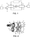
- the figure 1 represents a fuel circuit of an aircraft engine.
- a tank 1 of an airplane supplies a low pressure pump 2, then, through filters and exchangers 3, a high pressure pump 4.
- the pressurized fuel is supplied to a metering device 5, which supplies a combustion chamber 6 actuators and servo-valves 7; the excess flow returns upstream of the high pressure pump 4 via a return pipe 8, and, likewise, the fluid used in the actuators and servo-valves 7.
- This device does not limit the invention, which relates to a special pump, particularly useful in this application and this device, but perfectly applicable to others.
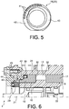
- the figure 2 illustrates, in perspective, the essential portions of the known high pressure pump 4 and which the invention should improve
- the figure 3 is a general plan of the device.
- the high pressure pump 4 is a gear pump, comprising a drive pinion 11 and a driven pinion 12, meshing together and delivering fuel between their teeth to accomplish pumping.
- Each of the pinions 11 and 12 comprises tails or ends of axes 13, 14 and 15, 16 at its two opposite sides, the first of which, to the right of the figures 2 and 3 , are supported by respective first bearings 17, 18, called fixed bearings with first sets 9, and the second, on the left in the figures, are supported by second bearings, called movable bearings 19, 20 with second sets 10.
- bearings 17 to 20 are all plain bearings, but the fixed bearings 17 and 18 are retained with a smaller clearance in the housings of a housing 24 than the movable bearings 19 and 20, which can thus move in the axial direction to pinch the pinions 11 and 12 and reduce the clearances which could allow the pumped fluid to recirculate towards the low pressures.
- the driving gear 11 is driven by a high pressure shaft 21, and a low pressure shaft 22 drives the impeller 23 of the low pressure pump 2.
- the pumps 2 and 4 are both integrated in the common housing 24.
- the low pressure shaft 22 is supported by an additional bearing 25 in a bore of the housing 24. Stops 26 limit the axial movements of the impeller 23, relying on the bearing 25.
- the movement of the drive shaft 21 is communicated to the low pressure shaft 22 by means of splines 27 between the drive pinion 11 and the ends of the shafts 21 and 22. A coupling of the pumps 2 and 4 is thus obtained.
- each of the bearings 17 to 20 is hollowed out by several reliefs, including a high pressure basin 33 and a low pressure basin 34 at the periphery of an inner axial face 35 (close to the gables 11 and 12), on both sides. another of a separation wall 60.
- the basins 33 and 34 are in respective communication with the volumes of fluids adjacent to the outlet and the inlet of the pump 4.
- the high pressure basin 33 communicates with an arcuate groove at high pressure 36, which opens onto the inner axial face 35, and, via a bore not shown, to a high pressure groove 37, which opens into an inner radial face 38 of the bearing 17 to 20.
- a groove low pressure 39 extends to the junction of the inner axial face 35 of the inner radial face 38 and communicates with the low pressure basin 34, by a collecting groove 40.
- the movable bearings 19 and 20 still have, in their known construction, a particular construction feature on their outer axial face, remote from the pinions 11 and 12: this face is divided into two portions in shape of crescents 42 and 43, which are located in different planes, separated by a shoulder provided with a seal 45 (visible at figure 6 ) which allows the crescent 42 to be exposed to the high pressure of the fluid and the crescent 43 to the low pressure.
- the movable bearings 19 and 20 are retained, at the location of the shoulder separating the crescents 42 and 43, in bores 44 of the housing 24, eccentric with respect to the axes of rotation of the pinions 11 and 12.
- the springs 30 compressed between the movable bearings 19 and 20 and a face 31 of the housing 24, adjacent to the inlet of the high pressure shaft 21, can be installed only where the crescent 42 is the widest, about a quarter of a circumference of the movable bearings 19 and 20.
- the thrust in the axial direction is then unbalanced and includes a moment around a transverse axis of the movable bearings 19 and 20, in order to balance an opposite moment produced by the pressure differences of the pumped fluid on the internal axial faces.
- the pressure forces exerted on the elements acting inside the pump can be detailed mainly like this.
- the pressure difference between the inlet and the outlet of the pump moves the pinions 11 and 12 towards the fluid inlet side, bringing them closer to the housing 24 and exerting a transverse load on the axle ends 13 to 16
- the greater pressure exerted on the outer axial face of the movable bearings 19 and 20, mainly on the crescent 42 exposed to the high pressure pushes the movable bearings 19 and 20 towards the pinions 11 and 12 and compresses them on the bearings.
- the springs 30, which also contribute to the pinching of the pinions 11 and 12, are useful when starting the pump 4, when no pressure difference is created there yet; the efforts they produce are then too weak to exert any real influence.
- the high pressure pump 4 therefore operates generally satisfactorily, but which depends on a sufficient rise in pressure to ensure the lubrication of the bearings 17 to 20 and the maintenance of the hydrodynamic lift of the axle ends 13 to 16 despite the operating oscillations, and also to reduce harmful recirculations around the pinions 11 and 12. Another possible weakness is due to the seal 29, responsible for the blockage of the housing 24.
- the realization of the invention which will Now be described purely by way of illustration, on the other hand offers satisfactory operation, even if the overpressure at its terminals is low or zero.
- the invention will be described by means of modifications made to the high pressure pump 4.
- the modified high pressure pump, characteristic of the invention, will be referenced by 4 '.
- the second seal 46 consists of a housing containing a spring which pushes back a sealing lip: the housing is here in a housing of the movable bearing 19, and the lip rubs against a lens of the pinion 11. Without being shows the arrangement, since it is similar, a similar seal is disposed at a corresponding location, between the movable bearing 20 and the driven pinion 12.
- a closed cavity 47 is formed, delimited by the housing 24, the movable bearing 19 or 20, the seal 46, the pinion 11 or 12, the shaft end 15 or 16, and a flange 48, belonging to the housing 24, and serving to insert the seal 29.
- the movable bearing 20 and of the driven pinion 12 the same applies in the absence of the seal 29 and of the flange 48, since the casing 24 is continuous at this location.
- this hydrodynamic wedge 49 and then of this hydrodynamic layer 50 depends on the properties of the fluid: it is easily formed with the most usual fluids (Newtonians), such as fuels, only at high pressure.
- the hydrodynamic layer 50 can therefore no longer be easily formed if the fluid remains at approximately the same pressure between the inlet and the outlet of the high pressure pump 4 '.
- the oscillations to which the pinions 11 and 12 are subjected then tend to maintain the unfavorable state of the figure 8B , where bearings 17 to 20 are exposed to impact damage even at high rotational speeds.
- Rheo-thickening fluids follow a curve 52, the slope of which becomes more and more steep as the shear rate increases, and therefore have an increasingly greater viscosity when they are subjected to shear.
- Such fluids include, for example, oils loaded with impurities, such as organic fibers. Their viscosity, greater when the shear rates are high, allows them to easily provide hydrodynamic lift. But these rate conditions of high shears are always met in the present situation, since they exist in the hydrodynamic wedge 49, at the start of the rotation or in the event of oscillations, since the speed gradient is important, because of the small thickness of this wedge ; and the shear rate is also important at high rotational speeds, once the hydrodynamic layer 50 has been formed.
- the lift performed by the fluid of the closed cavities 47 has on the contrary a preponderant role of damping the oscillations with irregular operations. It should be noted that a reverse arrangement could be adopted, that is to say that the closed cavities 37 could be on the side of the fixed bearings 17 and 18.
- Pinching of the pinions 11 and 12 is therefore ensured essentially or even completely by the springs 30, which is not harmful despite the weakness of these springs, since the pressure difference causing recirculation around the pinions 11 and 12 in the clearances 32 is no longer important and only a low pinching force now is enough to thwart it. Likewise, there is no longer any reason to exert a moment around a transverse axis on the movable bearings 19 and 20, since they are no longer subjected to tilting due to the pressure forces on their internal axial faces. 38.
- the weakening of the overpressure at the terminals of the high pressure pump 4 may, if excessive, be ineffective in ensuring recirculation in the fixed bearings 17 and 18.
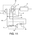
- Conventional recirculation, from the outlet side to the inlet side of the pump, is then replaced by an external recirculation, in accordance with a third important aspect of the invention shown in figure 11 .
- a booster pump 62 that can be added to the device downstream of the low pressure pump 2 to supplement the pressure rise supplied by the pump at high pressure 4 known.
- This booster pump 62 is located for example upstream of the filter 55 of the filters and exchangers 3.
- the fluid conduit passing successively through the low pressure pump 2, the booster pump 62, and the high pressure pump 4 ' carries the reference 63.
- the high pressure pump 4 ' delivering only a flow, but without adding additional pressure.
- the bearings associated with the closed cavities 37 are devoid of the basins, grooves, etc., shown in figure 4 , since they are not subject to a lift by the pumped fluid: they can have a regular cylindrical shape, but possibly be provided with grooves making the closed cavities 47 and the interfaces communicate more widely with the ends of axes 15 and 16
- the fixed bearings 17 and 18 may also be modified in the case of the external recirculation of the figure 11 , the collector groove 40 leading for example directly to the stitching 54 of the housing 24.
- the fluid in the closed cavities 47 will generally be at a moderate pressure, lower than that of the fluid pumped at the cruising speed of the apparatus.
- the seal 29 will therefore be less loaded and less prone to leaks. If any leaks did occur, they would probably be less dangerous than fuel leaks.
- opposite leaks, to chamber 24, are excluded, since the fuel is at a higher pressure. Either way, the greater viscosity of the fluid in the closed cavities 47 makes leakage more difficult.
- Fins 66 can be added to the casing 24 near the closed cavities 47, moreover the pipe 53 for returning the fuel to moderate pressure can circulate around said closed cavities 47, in order to reinforce the evacuation of the heat which is produced by their contained in ambient air or in recirculating fuel.
- FIG 7 from the tap 54, the pipe 53 is first dug in the casing 24 and passes close to the closed cavities 47, possibly snaking around them, before leaving the casing 24.
- the pipe 53 can be integrated to the casing 24, machined by drilling, or formed by assembling several parts of the casing 24.
- the length of the pipe 53 in the casing 24 can be increased to dissipate more heat therein, before the recirculating fuel joins the fluid conduit 63.
- the fins 66 can be added over the entire outer surface of the housing 24, and also have a greater density near the closed cavities 47. We have shown here over the entire surface of the housing 24 from the right of the gears 11 and 12, the flat face of the flange 48 being however devoid of it.
- the pump of the invention will therefore make it possible to improve the operation of the existing fuel supply circuits, by integrating easily with them, only minor modifications being necessary, without greatly complicating them and with great reliability.
- the invention would remain applicable to pumps in which the first bearings or fixed bearings 17 and 18, as well as the second bearings or movable bearings 19 and 20, would be integral with one another, and joined by a spacer, the bearings mobiles 19 and 20 then moving together.
Landscapes
- Engineering & Computer Science (AREA)
- Mechanical Engineering (AREA)
- General Engineering & Computer Science (AREA)
- Chemical & Material Sciences (AREA)
- Combustion & Propulsion (AREA)
- Rotary Pumps (AREA)
- Details And Applications Of Rotary Liquid Pumps (AREA)
Claims (14)
- Kraftstoffgetriebepumpe (4'), umfassend ein Gehäuse (24), zwei miteinander in Eingriff stehende Zahnräder (11, 12) in einer Gehäusekammer, zwei erste Lager (17, 18), die jeweils erste Achszapfen (13, 14) der Zahnräder abstützen, zwei zweite Lager (19, 20), die jeweils zweite Achszapfen (15, 16) der Zahnräder abstützen, wobei die ersten Lager und die zweiten Lager in der Gehäusekammer untergebracht sind, die ersten Achszapfen in den ersten Lagern (17, 18) mit ersten Spielen (9) drehbar gelagert sind und die zweiten Achszapfen in den zweiten Lagern (19, 20) mit zweiten Spielen (10) drehbar gelagert sind, die ersten und die zweiten Spiele Schichten einer Flüssigkeit zur hydrodynamischen Abstützung aufnehmen, dadurch gekennzeichnet, dass sie zwischen den zweiten Lagern (19, 20) und den Zahnrädern (11, 12) Dichtungen (46) umfasst, wobei die Dichtungen geschlossene Hohlräume (47) isolieren, welche die zweiten Spiele (10) einschließen und vom Gehäuse (24), den zweiten Lagern (19, 20) und den Zahnrädern (11, 12) begrenzt werden, wobei die geschlossenen Hohlräume eine Flüssigkeit mit einer Viskosität enthalten, die größer als diejenige einer von den Zahnrädern gepumpten Flüssigkeit ist, bei der es sich um einen Kraftstoff handelt.
- Getriebepumpe gemäß Anspruch 1, dadurch gekennzeichnet, dass die Flüssigkeit der geschlossenen Hohlräume (47) ein Rheo-Verdicker ist.
- Getriebepumpe gemäß einem der Ansprüche 1 oder 2, dadurch gekennzeichnet, dass entweder die ersten Lager oder die zweiten Lager in Axialrichtung der Achszapfen der Zahnräder im Gehäuse (24) beweglich sind und von auf dem Gehäuse (24) zusammengedrückten Federn (30) in Richtung der Zahnräder gedrückt werden.
- Getriebepumpe gemäß Anspruch 3, dadurch gekennzeichnet, dass sich die Federn auf gegenüberliegenden Umfangsabschnitten der äußeren Axialflächen der beweglichen Lager erstrecken.
- Getriebepumpe gemäß einem der Ansprüche 1 bis 4, dadurch gekennzeichnet, dass das Gehäuse (24) an einer Öffnung eine Dichtung (29) aufweist, wobei die Dichtung eine Welle (21) der Pumpe umgibt und sich an einem der geschlossenen Hohlräume (47) befindet.
- Getriebepumpe gemäß einem der Ansprüche 1 bis 5, dadurch gekennzeichnet, dass die Schichten zum hydrodynamischen Anheben der ersten Spiele (9) von Vorrichtungen zur Rückführung der durch die Pumpe (4') gepumpten Flüssigkeit gebildet werden, wobei die Vorrichtungen (33-40; 54) durch die ersten Spiele (9) verlaufen.
- Getriebepumpe gemäß Anspruch 6, dadurch gekennzeichnet, dass das Gehäuse eine Abzweigung (54) umfasst, welche die ersten Spiele (9) und das Äußere des Gehäuses (24) verbindet.
- Getriebepumpe gemäß einem der Ansprüche 1 bis 7, dadurch gekennzeichnet, dass sie zumindest vor den geschlossenen Hohlräumen (47) Wärmeableitungsrippen (66) auf dem Gehäuse (24) umfasst.
- Pumpvorrichtung, umfassend eine Getriebepumpe gemäß einem der Ansprüche 1 bis 8 und eine weitere Pumpe (2), die ebenfalls im Gehäuse (24) enthalten ist, wobei die Getriebepumpe (4') und die weitere Pumpe gekoppelt sind, indem sie über Antriebswellen (21, 22) miteinander verbunden sind.
- Pumpvorrichtung gemäß Anspruch 9, dadurch gekennzeichnet, dass es sich bei der Getriebepumpe um eine Hochdruckkraftstoffpumpe handelt, dass die weitere Pumpe (2) eine Niederdruckkraftstoffpumpe ist und dass die Vorrichtung einen Flüssigkeitskreislauf umfasst, der einen Kraftstoffauslass der Niederdruckpumpe mit einem Kraftstoffeinlass der Getriebepumpe verbindet.
- Pumpvorrichtung gemäß Anspruch 10, wobei die Getriebepumpe Anspruch 7 entspricht, dadurch gekennzeichnet, dass sie eine Flüssigkeitsleitung (53) umfasst, welche die Abzweigung (54) mit dem Flüssigkeitskreislauf zwischen dem Kraftstoffauslass der Niederdruckpumpe und dem Kraftstoffeinlass verbindet.
- Pumpvorrichtung gemäß Anspruch 11, dadurch gekennzeichnet, dass die Leitung (53) einen Abschnitt innerhalb des Gehäuses umfasst, der nahe den geschlossenen Hohlräumen (47) verläuft.
- Pumpvorrichtung, umfassend eine Getriebepumpe (4') gemäß einem der Ansprüche 1 bis 8, wobei es sich bei der Getriebepumpe um eine Hochdruckpumpe handelt, wobei die Vorrichtung darüber hinaus eine Niederdruckpumpe (2) und eine Flüssigkeitsleitung (63) umfasst, die durch die Niederdruckpumpe (2) und die Hochdruckpumpe (4') verläuft.
- Pumpvorrichtung gemäß Anspruch 13, dadurch gekennzeichnet, dass sie außerdem eine Förderpumpe (62) umfasst, durch welche die Leitung (63) stromabwärts von der Niederdruckpumpe (2) verläuft, wobei das Gehäuse (24) Abzweigungen (54) umfasst, welche die ersten Spiele (9) und das Äußere des Gehäuses (24) verbinden, und wobei die Abzweigungen mit einer Leitung (53) verbunden sind, welche stromaufwärts von der Förderpumpe (62) in die Leitung (63) mündet.
Applications Claiming Priority (2)
| Application Number | Priority Date | Filing Date | Title |
|---|---|---|---|
| FR1453372A FR3019856B1 (fr) | 2014-04-15 | 2014-04-15 | Pompe a engrenages, prevue notamment comme pompe a haute pression a carburant |
| PCT/FR2015/051001 WO2015159018A1 (fr) | 2014-04-15 | 2015-04-14 | Pompe a engrenages a carburant, prevue notamment comme pompe a haute pression |
Publications (2)
| Publication Number | Publication Date |
|---|---|
| EP3132123A1 EP3132123A1 (de) | 2017-02-22 |
| EP3132123B1 true EP3132123B1 (de) | 2020-09-09 |
Family
ID=51352559
Family Applications (1)
| Application Number | Title | Priority Date | Filing Date |
|---|---|---|---|
| EP15720387.8A Active EP3132123B1 (de) | 2014-04-15 | 2015-04-14 | Kraftstoffgetriebepumpe zur verwendung, im besonderen, als hochdruckpumpe |
Country Status (8)
| Country | Link |
|---|---|
| US (1) | US10094291B2 (de) |
| EP (1) | EP3132123B1 (de) |
| CN (1) | CN106415011B (de) |
| BR (1) | BR112016023339B1 (de) |
| CA (1) | CA2945890C (de) |
| FR (1) | FR3019856B1 (de) |
| RU (1) | RU2680902C2 (de) |
| WO (1) | WO2015159018A1 (de) |
Families Citing this family (7)
| Publication number | Priority date | Publication date | Assignee | Title |
|---|---|---|---|---|
| FR3036137B1 (fr) | 2015-05-13 | 2017-06-02 | Snecma | Vanne papillon de decharge de pression d'un compresseur pour turbomachine d'aeronef |
| FR3059718B1 (fr) | 2016-12-02 | 2019-06-21 | Safran Aircraft Engines | Dispositif hydromecanique de coupure a hysteresis pour systeme de lubrification de turbomachine |
| CN110685806A (zh) * | 2019-11-06 | 2020-01-14 | 四川航天中天动力装备有限责任公司 | 一种涡喷发动机供油机构用滑动轴承结构 |
| RU195531U1 (ru) * | 2019-11-18 | 2020-01-30 | Акционерное общество "Ярославский завод дизельной аппаратуры" | Топливоподкачивающий насос |
| CN111765062B (zh) * | 2020-06-10 | 2022-10-14 | 中国航发北京航科发动机控制系统科技有限公司 | 一种高低压组合式燃油泵结构 |
| JP2025542275A (ja) | 2022-12-19 | 2025-12-25 | トライアンフ・エンジン・コントロール・システムズ・リミテッド・ライアビリティ・カンパニー | ギアポンプの噛み合い部におけるキャビテーション低減のための容積拡大 |
| CN115977804B (zh) * | 2022-12-29 | 2025-08-12 | 北京空天技术研究所 | 一种基于双运动自由度活塞泵的主/预增压一体化系统 |
Family Cites Families (14)
| Publication number | Priority date | Publication date | Assignee | Title |
|---|---|---|---|---|
| US2891483A (en) * | 1956-04-13 | 1959-06-23 | Thompson Ramo Wooldridge Inc | Movable bushing for pressure loaded gear pumps |
| BE625348A (de) * | 1961-12-11 | |||
| US3528756A (en) * | 1968-12-04 | 1970-09-15 | Borg Warner | Pressure loaded pump |
| US3574492A (en) * | 1969-09-26 | 1971-04-13 | Gen Signal Corp | Bushing arrangement for rotary shafts |
| DD159097A1 (de) * | 1981-05-25 | 1983-02-16 | Gerhard Willner | Hydrostatische zahnradmaschine |
| US4787332A (en) * | 1986-02-12 | 1988-11-29 | Robotics, Inc. | Adhesive dispensing pump control system |
| US5417556A (en) * | 1994-03-08 | 1995-05-23 | Alliedsignal Inc. | Bearing for gear pump |
| US5641281A (en) * | 1995-11-20 | 1997-06-24 | Lci Corporation | Lubricating means for a gear pump |
| RU2395719C1 (ru) * | 2008-12-29 | 2010-07-27 | Государственное образовательное учреждение высшего профессионального образования "Братский государственный университет" | Шестеренный насос с принудительной смазкой подшипников скольжения |
| US9611847B2 (en) * | 2009-04-16 | 2017-04-04 | Eaton Industrial Corporation | Aircraft main engine fuel pump with multiple gear stages using shared journals |
| JP5984534B2 (ja) * | 2012-07-02 | 2016-09-06 | 日立オートモティブシステムズ株式会社 | ポンプ装置 |
| CN202746190U (zh) * | 2012-07-03 | 2013-02-20 | 泊姆克(天津)液压有限公司 | 一种高压齿轮泵 |
| FR2995053B1 (fr) | 2012-09-03 | 2016-03-04 | Snecma | Boite d'engrenages de prise de mouvement sur une turbomachine, composee d'une chaine cinematique a lignes d'engrenages s'etendant dans des plans non paralleles |
| FR3022951B1 (fr) | 2014-06-26 | 2020-01-24 | Safran Aircraft Engines | Pompe a deux etages, prevue notamment comme pompe principale d'alimentation d'un moteur d'avion en carburant |
-
2014
- 2014-04-15 FR FR1453372A patent/FR3019856B1/fr active Active
-
2015
- 2015-04-14 BR BR112016023339-5A patent/BR112016023339B1/pt active IP Right Grant
- 2015-04-14 EP EP15720387.8A patent/EP3132123B1/de active Active
- 2015-04-14 RU RU2016144149A patent/RU2680902C2/ru active
- 2015-04-14 CN CN201580020343.7A patent/CN106415011B/zh active Active
- 2015-04-14 WO PCT/FR2015/051001 patent/WO2015159018A1/fr not_active Ceased
- 2015-04-14 US US15/304,212 patent/US10094291B2/en active Active
- 2015-04-14 CA CA2945890A patent/CA2945890C/fr active Active
Non-Patent Citations (1)
| Title |
|---|
| None * |
Also Published As
| Publication number | Publication date |
|---|---|
| BR112016023339B1 (pt) | 2022-10-04 |
| WO2015159018A1 (fr) | 2015-10-22 |
| CN106415011A (zh) | 2017-02-15 |
| FR3019856B1 (fr) | 2019-05-31 |
| CN106415011B (zh) | 2019-03-01 |
| US10094291B2 (en) | 2018-10-09 |
| EP3132123A1 (de) | 2017-02-22 |
| FR3019856A1 (fr) | 2015-10-16 |
| US20170044986A1 (en) | 2017-02-16 |
| CA2945890A1 (fr) | 2015-10-22 |
| RU2016144149A (ru) | 2018-05-16 |
| BR112016023339A2 (pt) | 2017-12-12 |
| RU2016144149A3 (de) | 2018-08-21 |
| CA2945890C (fr) | 2021-12-14 |
| RU2680902C2 (ru) | 2019-02-28 |
Similar Documents
| Publication | Publication Date | Title |
|---|---|---|
| CA2945890C (fr) | Pompe a engrenages a carburant, prevue notamment comme pompe a haute pression | |
| CA2719472C (fr) | Dispositif et procede d'equilibrage de pression dans une enceinte palier de turboreacteur | |
| EP3042105B1 (de) | Rotorbaugruppe mit einem getriebeelement und ölverteilsystem | |
| FR3017413A1 (fr) | Turbomachine equipee d'un groupe de lubrification. | |
| CA2621837C (fr) | Systeme de deshuilage pour moteur d'aeronef | |
| FR3031786A1 (fr) | Integration d'une pompe en fut de pignon | |
| FR3114353A1 (fr) | Joint dynamique amélioré pour l’étanchéité d’un module de moteur d’aéronef | |
| FR3120914A1 (fr) | Module de soufflante equipe d’un dispositif de transfert d’huile | |
| EP4023909B1 (de) | Satellitenträger für ein reduktionsgetriebe für luftfahrzeug-turbotriebwerk | |
| FR3022951A1 (fr) | Pompe a deux etages, prevue notamment comme pompe principale d'alimentation d'un moteur d'avion en carburant | |
| EP3997353A1 (de) | Schmiermittelrückführung in einem wälzlager einer turbomaschine | |
| EP4469694B1 (de) | Gleitlager für eine flugzeugturbomaschine | |
| WO2026093685A1 (fr) | Système à étanchéité dynamique comprenant un segment d'étanchéité associé à un joint torique | |
| FR2981993A1 (fr) | Pompe a engrenages a cylindree variable pour turbomachine d'aeronef | |
| FR2957974A1 (fr) | Tube de degazage d'un turboreacteur, procede de montage d'un tel tube et turboreacteur avec un tel tube | |
| WO2026077713A1 (fr) | Désaérateur incurvé installé dans un reservoir d'huile pour turbomachine | |
| FR3039224B1 (fr) | Pompe a engrenages a palier hydrodynamique ameliore | |
| WO2026008949A1 (fr) | Systeme a etancheite dynamique comprenant un segment d'etancheite ameliore | |
| WO2025176957A1 (fr) | Dispositif d'alimentation en huile pour un reducteur mecanique d'une turbomachine d'aeronef | |
| EP4242489A1 (de) | Mechanisches reduktionsgetriebe für flugzeugturbomaschine | |
| WO2025120287A1 (fr) | Gicleur d'huile pour un reducteur de turbomachine d'aeronef | |
| FR3165297A1 (fr) | Dispositif de transfert fluidique multivoies comprenant des bagues de transfert de fluide assurant une étanchéité dynamique | |
| FR3167416A1 (fr) | Pivot pour palier hydrodynamique | |
| FR2684149A1 (fr) | Palier, notamment pour pompe ou turbine. | |
| FR3033381A1 (fr) | Joint a bague flottante |
Legal Events
| Date | Code | Title | Description |
|---|---|---|---|
| STAA | Information on the status of an ep patent application or granted ep patent |
Free format text: STATUS: THE INTERNATIONAL PUBLICATION HAS BEEN MADE |
|
| PUAI | Public reference made under article 153(3) epc to a published international application that has entered the european phase |
Free format text: ORIGINAL CODE: 0009012 |
|
| STAA | Information on the status of an ep patent application or granted ep patent |
Free format text: STATUS: REQUEST FOR EXAMINATION WAS MADE |
|
| 17P | Request for examination filed |
Effective date: 20161017 |
|
| AK | Designated contracting states |
Kind code of ref document: A1 Designated state(s): AL AT BE BG CH CY CZ DE DK EE ES FI FR GB GR HR HU IE IS IT LI LT LU LV MC MK MT NL NO PL PT RO RS SE SI SK SM TR |
|
| AX | Request for extension of the european patent |
Extension state: BA ME |
|
| DAV | Request for validation of the european patent (deleted) | ||
| DAX | Request for extension of the european patent (deleted) | ||
| STAA | Information on the status of an ep patent application or granted ep patent |
Free format text: STATUS: EXAMINATION IS IN PROGRESS |
|
| 17Q | First examination report despatched |
Effective date: 20180628 |
|
| GRAP | Despatch of communication of intention to grant a patent |
Free format text: ORIGINAL CODE: EPIDOSNIGR1 |
|
| STAA | Information on the status of an ep patent application or granted ep patent |
Free format text: STATUS: GRANT OF PATENT IS INTENDED |
|
| INTG | Intention to grant announced |
Effective date: 20200407 |
|
| GRAS | Grant fee paid |
Free format text: ORIGINAL CODE: EPIDOSNIGR3 |
|
| GRAA | (expected) grant |
Free format text: ORIGINAL CODE: 0009210 |
|
| STAA | Information on the status of an ep patent application or granted ep patent |
Free format text: STATUS: THE PATENT HAS BEEN GRANTED |
|
| AK | Designated contracting states |
Kind code of ref document: B1 Designated state(s): AL AT BE BG CH CY CZ DE DK EE ES FI FR GB GR HR HU IE IS IT LI LT LU LV MC MK MT NL NO PL PT RO RS SE SI SK SM TR |
|
| REG | Reference to a national code |
Ref country code: GB Ref legal event code: FG4D Free format text: NOT ENGLISH |
|
| REG | Reference to a national code |
Ref country code: AT Ref legal event code: REF Ref document number: 1311827 Country of ref document: AT Kind code of ref document: T Effective date: 20200915 Ref country code: CH Ref legal event code: EP |
|
| REG | Reference to a national code |
Ref country code: DE Ref legal event code: R096 Ref document number: 602015058744 Country of ref document: DE |
|
| REG | Reference to a national code |
Ref country code: IE Ref legal event code: FG4D Free format text: LANGUAGE OF EP DOCUMENT: FRENCH |
|
| REG | Reference to a national code |
Ref country code: LT Ref legal event code: MG4D |
|
| PG25 | Lapsed in a contracting state [announced via postgrant information from national office to epo] |
Ref country code: SE Free format text: LAPSE BECAUSE OF FAILURE TO SUBMIT A TRANSLATION OF THE DESCRIPTION OR TO PAY THE FEE WITHIN THE PRESCRIBED TIME-LIMIT Effective date: 20200909 Ref country code: BG Free format text: LAPSE BECAUSE OF FAILURE TO SUBMIT A TRANSLATION OF THE DESCRIPTION OR TO PAY THE FEE WITHIN THE PRESCRIBED TIME-LIMIT Effective date: 20201209 Ref country code: LT Free format text: LAPSE BECAUSE OF FAILURE TO SUBMIT A TRANSLATION OF THE DESCRIPTION OR TO PAY THE FEE WITHIN THE PRESCRIBED TIME-LIMIT Effective date: 20200909 Ref country code: HR Free format text: LAPSE BECAUSE OF FAILURE TO SUBMIT A TRANSLATION OF THE DESCRIPTION OR TO PAY THE FEE WITHIN THE PRESCRIBED TIME-LIMIT Effective date: 20200909 Ref country code: GR Free format text: LAPSE BECAUSE OF FAILURE TO SUBMIT A TRANSLATION OF THE DESCRIPTION OR TO PAY THE FEE WITHIN THE PRESCRIBED TIME-LIMIT Effective date: 20201210 Ref country code: FI Free format text: LAPSE BECAUSE OF FAILURE TO SUBMIT A TRANSLATION OF THE DESCRIPTION OR TO PAY THE FEE WITHIN THE PRESCRIBED TIME-LIMIT Effective date: 20200909 Ref country code: NO Free format text: LAPSE BECAUSE OF FAILURE TO SUBMIT A TRANSLATION OF THE DESCRIPTION OR TO PAY THE FEE WITHIN THE PRESCRIBED TIME-LIMIT Effective date: 20201209 |
|
| REG | Reference to a national code |
Ref country code: AT Ref legal event code: MK05 Ref document number: 1311827 Country of ref document: AT Kind code of ref document: T Effective date: 20200909 |
|
| REG | Reference to a national code |
Ref country code: NL Ref legal event code: MP Effective date: 20200909 |
|
| PG25 | Lapsed in a contracting state [announced via postgrant information from national office to epo] |
Ref country code: LV Free format text: LAPSE BECAUSE OF FAILURE TO SUBMIT A TRANSLATION OF THE DESCRIPTION OR TO PAY THE FEE WITHIN THE PRESCRIBED TIME-LIMIT Effective date: 20200909 Ref country code: RS Free format text: LAPSE BECAUSE OF FAILURE TO SUBMIT A TRANSLATION OF THE DESCRIPTION OR TO PAY THE FEE WITHIN THE PRESCRIBED TIME-LIMIT Effective date: 20200909 Ref country code: PL Free format text: LAPSE BECAUSE OF FAILURE TO SUBMIT A TRANSLATION OF THE DESCRIPTION OR TO PAY THE FEE WITHIN THE PRESCRIBED TIME-LIMIT Effective date: 20200909 |
|
| PG25 | Lapsed in a contracting state [announced via postgrant information from national office to epo] |
Ref country code: CZ Free format text: LAPSE BECAUSE OF FAILURE TO SUBMIT A TRANSLATION OF THE DESCRIPTION OR TO PAY THE FEE WITHIN THE PRESCRIBED TIME-LIMIT Effective date: 20200909 Ref country code: PT Free format text: LAPSE BECAUSE OF FAILURE TO SUBMIT A TRANSLATION OF THE DESCRIPTION OR TO PAY THE FEE WITHIN THE PRESCRIBED TIME-LIMIT Effective date: 20210111 Ref country code: NL Free format text: LAPSE BECAUSE OF FAILURE TO SUBMIT A TRANSLATION OF THE DESCRIPTION OR TO PAY THE FEE WITHIN THE PRESCRIBED TIME-LIMIT Effective date: 20200909 Ref country code: SM Free format text: LAPSE BECAUSE OF FAILURE TO SUBMIT A TRANSLATION OF THE DESCRIPTION OR TO PAY THE FEE WITHIN THE PRESCRIBED TIME-LIMIT Effective date: 20200909 Ref country code: RO Free format text: LAPSE BECAUSE OF FAILURE TO SUBMIT A TRANSLATION OF THE DESCRIPTION OR TO PAY THE FEE WITHIN THE PRESCRIBED TIME-LIMIT Effective date: 20200909 Ref country code: EE Free format text: LAPSE BECAUSE OF FAILURE TO SUBMIT A TRANSLATION OF THE DESCRIPTION OR TO PAY THE FEE WITHIN THE PRESCRIBED TIME-LIMIT Effective date: 20200909 |
|
| PG25 | Lapsed in a contracting state [announced via postgrant information from national office to epo] |
Ref country code: ES Free format text: LAPSE BECAUSE OF FAILURE TO SUBMIT A TRANSLATION OF THE DESCRIPTION OR TO PAY THE FEE WITHIN THE PRESCRIBED TIME-LIMIT Effective date: 20200909 Ref country code: AT Free format text: LAPSE BECAUSE OF FAILURE TO SUBMIT A TRANSLATION OF THE DESCRIPTION OR TO PAY THE FEE WITHIN THE PRESCRIBED TIME-LIMIT Effective date: 20200909 Ref country code: AL Free format text: LAPSE BECAUSE OF FAILURE TO SUBMIT A TRANSLATION OF THE DESCRIPTION OR TO PAY THE FEE WITHIN THE PRESCRIBED TIME-LIMIT Effective date: 20200909 Ref country code: IS Free format text: LAPSE BECAUSE OF FAILURE TO SUBMIT A TRANSLATION OF THE DESCRIPTION OR TO PAY THE FEE WITHIN THE PRESCRIBED TIME-LIMIT Effective date: 20210109 |
|
| REG | Reference to a national code |
Ref country code: DE Ref legal event code: R097 Ref document number: 602015058744 Country of ref document: DE |
|
| PG25 | Lapsed in a contracting state [announced via postgrant information from national office to epo] |
Ref country code: SK Free format text: LAPSE BECAUSE OF FAILURE TO SUBMIT A TRANSLATION OF THE DESCRIPTION OR TO PAY THE FEE WITHIN THE PRESCRIBED TIME-LIMIT Effective date: 20200909 |
|
| PLBE | No opposition filed within time limit |
Free format text: ORIGINAL CODE: 0009261 |
|
| STAA | Information on the status of an ep patent application or granted ep patent |
Free format text: STATUS: NO OPPOSITION FILED WITHIN TIME LIMIT |
|
| 26N | No opposition filed |
Effective date: 20210610 |
|
| PG25 | Lapsed in a contracting state [announced via postgrant information from national office to epo] |
Ref country code: SI Free format text: LAPSE BECAUSE OF FAILURE TO SUBMIT A TRANSLATION OF THE DESCRIPTION OR TO PAY THE FEE WITHIN THE PRESCRIBED TIME-LIMIT Effective date: 20200909 Ref country code: DK Free format text: LAPSE BECAUSE OF FAILURE TO SUBMIT A TRANSLATION OF THE DESCRIPTION OR TO PAY THE FEE WITHIN THE PRESCRIBED TIME-LIMIT Effective date: 20200909 |
|
| PG25 | Lapsed in a contracting state [announced via postgrant information from national office to epo] |
Ref country code: MC Free format text: LAPSE BECAUSE OF FAILURE TO SUBMIT A TRANSLATION OF THE DESCRIPTION OR TO PAY THE FEE WITHIN THE PRESCRIBED TIME-LIMIT Effective date: 20200909 |
|
| PG25 | Lapsed in a contracting state [announced via postgrant information from national office to epo] |
Ref country code: LU Free format text: LAPSE BECAUSE OF NON-PAYMENT OF DUE FEES Effective date: 20210414 |
|
| REG | Reference to a national code |
Ref country code: BE Ref legal event code: MM Effective date: 20210430 |
|
| PG25 | Lapsed in a contracting state [announced via postgrant information from national office to epo] |
Ref country code: LI Free format text: LAPSE BECAUSE OF NON-PAYMENT OF DUE FEES Effective date: 20210430 Ref country code: CH Free format text: LAPSE BECAUSE OF NON-PAYMENT OF DUE FEES Effective date: 20210430 |
|
| PG25 | Lapsed in a contracting state [announced via postgrant information from national office to epo] |
Ref country code: IE Free format text: LAPSE BECAUSE OF NON-PAYMENT OF DUE FEES Effective date: 20210414 |
|
| PG25 | Lapsed in a contracting state [announced via postgrant information from national office to epo] |
Ref country code: IS Free format text: LAPSE BECAUSE OF FAILURE TO SUBMIT A TRANSLATION OF THE DESCRIPTION OR TO PAY THE FEE WITHIN THE PRESCRIBED TIME-LIMIT Effective date: 20210109 |
|
| PG25 | Lapsed in a contracting state [announced via postgrant information from national office to epo] |
Ref country code: BE Free format text: LAPSE BECAUSE OF NON-PAYMENT OF DUE FEES Effective date: 20210430 |
|
| PG25 | Lapsed in a contracting state [announced via postgrant information from national office to epo] |
Ref country code: HU Free format text: LAPSE BECAUSE OF FAILURE TO SUBMIT A TRANSLATION OF THE DESCRIPTION OR TO PAY THE FEE WITHIN THE PRESCRIBED TIME-LIMIT; INVALID AB INITIO Effective date: 20150414 |
|
| PG25 | Lapsed in a contracting state [announced via postgrant information from national office to epo] |
Ref country code: CY Free format text: LAPSE BECAUSE OF FAILURE TO SUBMIT A TRANSLATION OF THE DESCRIPTION OR TO PAY THE FEE WITHIN THE PRESCRIBED TIME-LIMIT Effective date: 20200909 |
|
| PG25 | Lapsed in a contracting state [announced via postgrant information from national office to epo] |
Ref country code: MK Free format text: LAPSE BECAUSE OF FAILURE TO SUBMIT A TRANSLATION OF THE DESCRIPTION OR TO PAY THE FEE WITHIN THE PRESCRIBED TIME-LIMIT Effective date: 20200909 |
|
| PG25 | Lapsed in a contracting state [announced via postgrant information from national office to epo] |
Ref country code: TR Free format text: LAPSE BECAUSE OF FAILURE TO SUBMIT A TRANSLATION OF THE DESCRIPTION OR TO PAY THE FEE WITHIN THE PRESCRIBED TIME-LIMIT Effective date: 20200909 |
|
| PG25 | Lapsed in a contracting state [announced via postgrant information from national office to epo] |
Ref country code: MT Free format text: LAPSE BECAUSE OF FAILURE TO SUBMIT A TRANSLATION OF THE DESCRIPTION OR TO PAY THE FEE WITHIN THE PRESCRIBED TIME-LIMIT Effective date: 20200909 |
|
| PGFP | Annual fee paid to national office [announced via postgrant information from national office to epo] |
Ref country code: DE Payment date: 20250417 Year of fee payment: 11 |
|
| PGFP | Annual fee paid to national office [announced via postgrant information from national office to epo] |
Ref country code: IT Payment date: 20250430 Year of fee payment: 11 |
|
| PGFP | Annual fee paid to national office [announced via postgrant information from national office to epo] |
Ref country code: FR Payment date: 20250422 Year of fee payment: 11 |
|
| PGFP | Annual fee paid to national office [announced via postgrant information from national office to epo] |
Ref country code: GB Payment date: 20260327 Year of fee payment: 12 |