EP3132133B1 - Moteur à combustion interne avec un système de pompe à carburant à injection directe à course variable et procédé pour contrôler le moteur - Google Patents
Moteur à combustion interne avec un système de pompe à carburant à injection directe à course variable et procédé pour contrôler le moteur Download PDFInfo
- Publication number
- EP3132133B1 EP3132133B1 EP15719098.4A EP15719098A EP3132133B1 EP 3132133 B1 EP3132133 B1 EP 3132133B1 EP 15719098 A EP15719098 A EP 15719098A EP 3132133 B1 EP3132133 B1 EP 3132133B1
- Authority
- EP
- European Patent Office
- Prior art keywords
- engine
- stroke
- pump
- fuel
- fuel pump
- Prior art date
- Legal status (The legal status is an assumption and is not a legal conclusion. Google has not performed a legal analysis and makes no representation as to the accuracy of the status listed.)
- Active
Links
Images



Classifications
-
- F—MECHANICAL ENGINEERING; LIGHTING; HEATING; WEAPONS; BLASTING
- F02—COMBUSTION ENGINES; HOT-GAS OR COMBUSTION-PRODUCT ENGINE PLANTS
- F02D—CONTROLLING COMBUSTION ENGINES
- F02D41/00—Electrical control of supply of combustible mixture or its constituents
- F02D41/30—Controlling fuel injection
- F02D41/38—Controlling fuel injection of the high pressure type
-
- F—MECHANICAL ENGINEERING; LIGHTING; HEATING; WEAPONS; BLASTING
- F02—COMBUSTION ENGINES; HOT-GAS OR COMBUSTION-PRODUCT ENGINE PLANTS
- F02M—SUPPLYING COMBUSTION ENGINES IN GENERAL WITH COMBUSTIBLE MIXTURES OR CONSTITUENTS THEREOF
- F02M63/00—Other fuel-injection apparatus having pertinent characteristics not provided for in groups F02M39/00 - F02M57/00 or F02M67/00; Details, component parts, or accessories of fuel-injection apparatus, not provided for in, or of interest apart from, the apparatus of groups F02M39/00 - F02M61/00 or F02M67/00; Combination of fuel pump with other devices, e.g. lubricating oil pump
- F02M63/02—Fuel-injection apparatus having several injectors fed by a common pumping element, or having several pumping elements feeding a common injector; Fuel-injection apparatus having provisions for cutting-out pumps, pumping elements, or injectors; Fuel-injection apparatus having provisions for variably interconnecting pumping elements and injectors alternatively
- F02M63/0225—Fuel-injection apparatus having a common rail feeding several injectors ; Means for varying pressure in common rails; Pumps feeding common rails
- F02M63/023—Means for varying pressure in common rails
-
- F—MECHANICAL ENGINEERING; LIGHTING; HEATING; WEAPONS; BLASTING
- F02—COMBUSTION ENGINES; HOT-GAS OR COMBUSTION-PRODUCT ENGINE PLANTS
- F02D—CONTROLLING COMBUSTION ENGINES
- F02D41/00—Electrical control of supply of combustible mixture or its constituents
- F02D41/30—Controlling fuel injection
- F02D41/38—Controlling fuel injection of the high pressure type
- F02D41/3809—Common rail control systems
-
- F—MECHANICAL ENGINEERING; LIGHTING; HEATING; WEAPONS; BLASTING
- F02—COMBUSTION ENGINES; HOT-GAS OR COMBUSTION-PRODUCT ENGINE PLANTS
- F02D—CONTROLLING COMBUSTION ENGINES
- F02D41/00—Electrical control of supply of combustible mixture or its constituents
- F02D41/30—Controlling fuel injection
- F02D41/38—Controlling fuel injection of the high pressure type
- F02D41/3809—Common rail control systems
- F02D41/3836—Controlling the fuel pressure
- F02D41/3845—Controlling the fuel pressure by controlling the flow into the common rail, e.g. the amount of fuel pumped
-
- F—MECHANICAL ENGINEERING; LIGHTING; HEATING; WEAPONS; BLASTING
- F02—COMBUSTION ENGINES; HOT-GAS OR COMBUSTION-PRODUCT ENGINE PLANTS
- F02M—SUPPLYING COMBUSTION ENGINES IN GENERAL WITH COMBUSTIBLE MIXTURES OR CONSTITUENTS THEREOF
- F02M59/00—Pumps specially adapted for fuel-injection and not provided for in groups F02M39/00 -F02M57/00, e.g. rotary cylinder-block type of pumps
- F02M59/02—Pumps specially adapted for fuel-injection and not provided for in groups F02M39/00 -F02M57/00, e.g. rotary cylinder-block type of pumps of reciprocating-piston or reciprocating-cylinder type
- F02M59/10—Pumps specially adapted for fuel-injection and not provided for in groups F02M39/00 -F02M57/00, e.g. rotary cylinder-block type of pumps of reciprocating-piston or reciprocating-cylinder type characterised by the piston-drive
- F02M59/102—Mechanical drive, e.g. tappets or cams
-
- F—MECHANICAL ENGINEERING; LIGHTING; HEATING; WEAPONS; BLASTING
- F02—COMBUSTION ENGINES; HOT-GAS OR COMBUSTION-PRODUCT ENGINE PLANTS
- F02M—SUPPLYING COMBUSTION ENGINES IN GENERAL WITH COMBUSTIBLE MIXTURES OR CONSTITUENTS THEREOF
- F02M59/00—Pumps specially adapted for fuel-injection and not provided for in groups F02M39/00 -F02M57/00, e.g. rotary cylinder-block type of pumps
- F02M59/02—Pumps specially adapted for fuel-injection and not provided for in groups F02M39/00 -F02M57/00, e.g. rotary cylinder-block type of pumps of reciprocating-piston or reciprocating-cylinder type
- F02M59/10—Pumps specially adapted for fuel-injection and not provided for in groups F02M39/00 -F02M57/00, e.g. rotary cylinder-block type of pumps of reciprocating-piston or reciprocating-cylinder type characterised by the piston-drive
- F02M59/105—Pumps specially adapted for fuel-injection and not provided for in groups F02M39/00 -F02M57/00, e.g. rotary cylinder-block type of pumps of reciprocating-piston or reciprocating-cylinder type characterised by the piston-drive hydraulic drive
-
- F—MECHANICAL ENGINEERING; LIGHTING; HEATING; WEAPONS; BLASTING
- F02—COMBUSTION ENGINES; HOT-GAS OR COMBUSTION-PRODUCT ENGINE PLANTS
- F02M—SUPPLYING COMBUSTION ENGINES IN GENERAL WITH COMBUSTIBLE MIXTURES OR CONSTITUENTS THEREOF
- F02M59/00—Pumps specially adapted for fuel-injection and not provided for in groups F02M39/00 -F02M57/00, e.g. rotary cylinder-block type of pumps
- F02M59/20—Varying fuel delivery in quantity or timing
- F02M59/22—Varying quantity or timing by adjusting cylinder-head space
-
- F—MECHANICAL ENGINEERING; LIGHTING; HEATING; WEAPONS; BLASTING
- F02—COMBUSTION ENGINES; HOT-GAS OR COMBUSTION-PRODUCT ENGINE PLANTS
- F02M—SUPPLYING COMBUSTION ENGINES IN GENERAL WITH COMBUSTIBLE MIXTURES OR CONSTITUENTS THEREOF
- F02M59/00—Pumps specially adapted for fuel-injection and not provided for in groups F02M39/00 -F02M57/00, e.g. rotary cylinder-block type of pumps
- F02M59/20—Varying fuel delivery in quantity or timing
- F02M59/30—Varying fuel delivery in quantity or timing with variable-length-stroke pistons
-
- F—MECHANICAL ENGINEERING; LIGHTING; HEATING; WEAPONS; BLASTING
- F02—COMBUSTION ENGINES; HOT-GAS OR COMBUSTION-PRODUCT ENGINE PLANTS
- F02M—SUPPLYING COMBUSTION ENGINES IN GENERAL WITH COMBUSTIBLE MIXTURES OR CONSTITUENTS THEREOF
- F02M63/00—Other fuel-injection apparatus having pertinent characteristics not provided for in groups F02M39/00 - F02M57/00 or F02M67/00; Details, component parts, or accessories of fuel-injection apparatus, not provided for in, or of interest apart from, the apparatus of groups F02M39/00 - F02M61/00 or F02M67/00; Combination of fuel pump with other devices, e.g. lubricating oil pump
- F02M63/02—Fuel-injection apparatus having several injectors fed by a common pumping element, or having several pumping elements feeding a common injector; Fuel-injection apparatus having provisions for cutting-out pumps, pumping elements, or injectors; Fuel-injection apparatus having provisions for variably interconnecting pumping elements and injectors alternatively
- F02M63/0225—Fuel-injection apparatus having a common rail feeding several injectors ; Means for varying pressure in common rails; Pumps feeding common rails
- F02M63/0265—Pumps feeding common rails
-
- F—MECHANICAL ENGINEERING; LIGHTING; HEATING; WEAPONS; BLASTING
- F02—COMBUSTION ENGINES; HOT-GAS OR COMBUSTION-PRODUCT ENGINE PLANTS
- F02B—INTERNAL-COMBUSTION PISTON ENGINES; COMBUSTION ENGINES IN GENERAL
- F02B75/00—Other engines
- F02B75/12—Other methods of operation
- F02B2075/125—Direct injection in the combustion chamber for spark ignition engines, i.e. not in pre-combustion chamber
-
- F—MECHANICAL ENGINEERING; LIGHTING; HEATING; WEAPONS; BLASTING
- F02—COMBUSTION ENGINES; HOT-GAS OR COMBUSTION-PRODUCT ENGINE PLANTS
- F02D—CONTROLLING COMBUSTION ENGINES
- F02D41/00—Electrical control of supply of combustible mixture or its constituents
- F02D41/30—Controlling fuel injection
- F02D41/38—Controlling fuel injection of the high pressure type
- F02D2041/389—Controlling fuel injection of the high pressure type for injecting directly into the cylinder
-
- F—MECHANICAL ENGINEERING; LIGHTING; HEATING; WEAPONS; BLASTING
- F02—COMBUSTION ENGINES; HOT-GAS OR COMBUSTION-PRODUCT ENGINE PLANTS
- F02D—CONTROLLING COMBUSTION ENGINES
- F02D2200/00—Input parameters for engine control
- F02D2200/02—Input parameters for engine control the parameters being related to the engine
- F02D2200/021—Engine temperature
-
- F—MECHANICAL ENGINEERING; LIGHTING; HEATING; WEAPONS; BLASTING
- F02—COMBUSTION ENGINES; HOT-GAS OR COMBUSTION-PRODUCT ENGINE PLANTS
- F02D—CONTROLLING COMBUSTION ENGINES
- F02D2200/00—Input parameters for engine control
- F02D2200/02—Input parameters for engine control the parameters being related to the engine
- F02D2200/06—Fuel or fuel supply system parameters
- F02D2200/0602—Fuel pressure
-
- F—MECHANICAL ENGINEERING; LIGHTING; HEATING; WEAPONS; BLASTING
- F02—COMBUSTION ENGINES; HOT-GAS OR COMBUSTION-PRODUCT ENGINE PLANTS
- F02D—CONTROLLING COMBUSTION ENGINES
- F02D2200/00—Input parameters for engine control
- F02D2200/02—Input parameters for engine control the parameters being related to the engine
- F02D2200/06—Fuel or fuel supply system parameters
- F02D2200/0606—Fuel temperature
-
- F—MECHANICAL ENGINEERING; LIGHTING; HEATING; WEAPONS; BLASTING
- F02—COMBUSTION ENGINES; HOT-GAS OR COMBUSTION-PRODUCT ENGINE PLANTS
- F02D—CONTROLLING COMBUSTION ENGINES
- F02D2200/00—Input parameters for engine control
- F02D2200/02—Input parameters for engine control the parameters being related to the engine
- F02D2200/10—Parameters related to the engine output, e.g. engine torque or engine speed
- F02D2200/101—Engine speed
-
- F—MECHANICAL ENGINEERING; LIGHTING; HEATING; WEAPONS; BLASTING
- F02—COMBUSTION ENGINES; HOT-GAS OR COMBUSTION-PRODUCT ENGINE PLANTS
- F02D—CONTROLLING COMBUSTION ENGINES
- F02D2200/00—Input parameters for engine control
- F02D2200/60—Input parameters for engine control said parameters being related to the driver demands or status
- F02D2200/602—Pedal position
-
- Y—GENERAL TAGGING OF NEW TECHNOLOGICAL DEVELOPMENTS; GENERAL TAGGING OF CROSS-SECTIONAL TECHNOLOGIES SPANNING OVER SEVERAL SECTIONS OF THE IPC; TECHNICAL SUBJECTS COVERED BY FORMER USPC CROSS-REFERENCE ART COLLECTIONS [XRACs] AND DIGESTS
- Y02—TECHNOLOGIES OR APPLICATIONS FOR MITIGATION OR ADAPTATION AGAINST CLIMATE CHANGE
- Y02T—CLIMATE CHANGE MITIGATION TECHNOLOGIES RELATED TO TRANSPORTATION
- Y02T10/00—Road transport of goods or passengers
- Y02T10/10—Internal combustion engine [ICE] based vehicles
- Y02T10/12—Improving ICE efficiencies
Definitions
- the present disclosure relates generally to vehicle fuel systems and, more particularly, to variable stroke direct injection (DI) fuel pump systems.
- DI direct injection
- the variable fuel pump actuator assembly includes an actuator member in communication with a control valve and configured to actuate the stroke member in response to a pressure of hydraulic fluid at the actuator member; the control valve configured to control the hydraulic fluid pressure at the actuator member by controlling a flow of hydraulic fluid to the actuator member; and a hydraulic fluid pump configured to pump the hydraulic fluid to the control valve and selectively to the actuator member in response to actuation by one or more lobes of a camshaft.
- the system also includes an engine control unit (ECU) configured to control a variable stroke of the stroke member by controlling the control valve to deliver a controlled amount of hydraulic fluid pressure to the actuation member based on one or more operating parameters of the DI engine.
- ECU engine control unit
- an engine control unit is configured to control the variable valve control system as well as an associated variable fuel pump actuation assembly for the DI fuel pump to selectively command no (zero) stroke through full stroke of the DI fuel pump.
- the ECU is able to fully control the stroke of the DI fuel pump based on engine operating parameters to decrease pumping losses based on or while utilizing the existing variable valve control system.
- the ECU could command no stroke of the DI fuel pump during low engine load or deceleration fuel cutoff (DFCO) events. Decreased pumping losses results in increased fuel economy, and potentially decreased noise/vibration/harshness (NVH) at low engine loads, e.g., idle.
- DFCO deceleration fuel cutoff
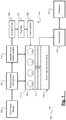
- the DI engine system 100 includes a DI engine 104 configured to combust an air/fuel mixture within a plurality of cylinders 108 ("cylinders 108") of a cylinder head 110 to generate drive torque. While four cylinders 108 are illustrated, it will be appreciated that the DI engine 104 could include other numbers of cylinders (2, 3, 5, 6, 8, 10, etc.). Specifically, the air is drawn into the DI engine 104 through an air induction system (not shown) and distributed to the cylinders 108 through intake ducts/ports whereby the airflow is controlled by respective intake valves 112.
- the air in the cylinders 108 is combined with fuel, e.g., gasoline, which is injected directly into the cylinders 108.
- the fuel is provided by a DI fuel system 124 that includes a plurality of fuel injectors 128 associated with the plurality of cylinders 108, respectively.
- the DI fuel system 124 also includes a fuel rail 132 that houses or stores fuel for the fuel injectors 128 to inject. Because the fuel injectors 128 share the fuel rail 132, the fuel rail 132 is also referred to as a common fuel rail.
- the DI fuel system 124 further includes a DI fuel pump 136 that pumps fuel from a fuel tank (not shown) and into the fuel rail 132.
- the fuel stored in the fuel rail 132 is highly pressurized at a desired pressure, which varies based on the pumping of the DI fuel pump 136 and the injection by the fuel injectors 128.
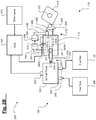
- the variable pump actuator assembly 212 is actuated by at least one fuel pump lobe 216 of camshaft 120 and selectively controlled by the ECU 152 to provide the desired stroke to a stroke actuator 220 of the DI fuel pump 136.
- a number of the fuel pump lobes 216 are equal to a number of the cylinders 108.
- the variable fuel pump actuator assembly 212 is configured to actuate the stroke actuator 220 of the DI fuel pump 136, as will be discussed in greater detail below.
- the rocker arm 254 is operable to actuate the oil pump 262 and is in contact with a fixed pivot 266.
- the oil pump 262 has a lash adjuster function and is operable to pump oil supplied from an oil circuit 288 to the actuator member 270, which is in engagement with the stroke actuator 220 or stroke member 278. Oil is supplied to the oil pump 262 from the oil circuit 288 via an oil supply line 292. While oil is discussed herein, it will be appreciated that another suitable hydraulic fluid could be utilized.
- the solenoid or other controllable valve 224 is configured to selectively control the amount of oil pumped to the actuator member 270 to thereby selectively control the stroke of stroke member 278.
- the ECU 152 receives signals from various sensors indicative of various operating parameters of the DI engine system 100.
- An engine speed sensor 228 is configured to measure a rotational speed of the crankshaft 140 ("engine speed"), e.g., in revolutions per minute (RPM).
- a fuel pressure sensor 232 is configured to measure a pressure of the fuel ("fuel pressure") in the fuel rail 132. It should be appreciated that the fuel pressure sensor 232 could alternatively be configured to measure the pressure of the fuel at a different point in the DI fuel system 124, e.g., at the DI fuel pump 136.
- a temperature sensor 236 is configured to measure a temperature of the DI engine system 100 ("temperature").
- the ECU 152 receives the engine speed, the fuel pressure, and the temperature from the sensors described above. In addition to, and as previously described, the ECU 152 also receives driver input from the driver input device 156, such as a depression of an accelerator pedal (also known as "accelerator pedal position"). This accelerator pedal position corresponds to a load on the DI engine 104. Based on at least one of these engine operating parameters, the ECU 152 controls the stroke of the DI fuel pump 136 by controlling the variable valve control system 116 and, in particular, the variable fuel pump actuator assembly 212. More specifically, the ECU 152 controls the stroke activation of the variable fuel pump actuator assembly 212, which affects the stroke of the DI fuel pump 136 (via the stroke actuator 220).
- driver input device 156 such as a depression of an accelerator pedal (also known as "accelerator pedal position"). This accelerator pedal position corresponds to a load on the DI engine 104.
- the ECU 152 controls the stroke of the DI fuel pump 136 by controlling the variable valve control system 116
- Examples of the ECU 152 commanding a shorter stroke of the DI fuel pump 136 include, but are not limited to, low engine speed, low/small accelerator pedal depression (low engine load), low temperature, and high fuel pressure.
- the ECU 152 is configured to disable the pumping of fuel by DI fuel pump 136 for at least one stroke by providing zero or no stroke activation to the actuator member 270.
- the ECU 152 could disable the pumping of fuel by the DI fuel pump 136 for a plurality of strokes or for all strokes by diverting substantially all of the oil pumped by oil pump 262 for the desired number of strokes.
- the ECU 152 is configured to control the solenoid valve 224 based on engine operating parameter(s) to control the stroke of the DI fuel pump 136. More specifically, the solenoid valve 224 is operable to control the flow of oil from the oil pump 262 to the actuator assembly 270, thereby selectively disabling or reducing the activation of actuator member 270 and, in turn, selectively disabling or reducing the pumping of fuel by DI fuel pump 136.
- One example of the one or more engine operating parameters is fuel pressure.
- the fuel pressure sensor 232 could be configured to measure the fuel pressure in the DI fuel pump 136 as illustrated. Examples of other inputs 274 used by the ECU 152 include engine speed, temperature, and driver input, such as accelerator pedal position.
- the communication device 300 is also configured to communicate with other components of the DI engine 104, e.g., an electronic throttle control (ETC) unit.
- the processor 304 is configured to process information received via the communication device 300 and to prepare information for transmission via the communication device 300. In some implementations, the processor 304 performs other functions including, but not limited to, loading and executing an operating system and performing read/write operations at the memory 308.
- the memory 308 is any suitable storage medium (flash, hard disk, etc.). It should be appreciated that the term "processor" as used herein refers to both a single processor and to two or more processors operating in a parallel or distributed architecture.
Landscapes
- Engineering & Computer Science (AREA)
- Chemical & Material Sciences (AREA)
- Combustion & Propulsion (AREA)
- Mechanical Engineering (AREA)
- General Engineering & Computer Science (AREA)
- Fuel-Injection Apparatus (AREA)
- Valve Device For Special Equipments (AREA)
- Output Control And Ontrol Of Special Type Engine (AREA)
Claims (15)
- Moteur, comprenant une culasse (110), un arbre à cames de moteur (120) et un système de pompe à carburant à injection directe à course variable, le système comprenant :une pompe à carburant à injection directe (DI) (136) comportant un élément de course (278) et configurée pour pomper une quantité de carburant sur la base d'une course de l'élément de course (278) ;un ensemble actionneur de pompe à carburant variable (212) configuré pour activer la pompe à carburant DI (136), l'ensemble actionneur de pompe à carburant variable (212) comprenant :un élément actionneur (270) en communication fluidique avec une soupape de régulation (224) et configuré pour actionner l'élément de course en réponse à une pression de fluide hydraulique au niveau de l'élément actionneur (270),la soupape de régulation (224) étant configurée pour réguler la pression de fluide au niveau de l'élément actionneur (270) en régulant un écoulement de fluide hydraulique vers l'élément actionneur (270), etune pompe à fluide hydraulique (262) configurée pour pomper le fluide hydraulique vers la soupape de régulation (224) et sélectivement vers l'élément actionneur (270), en réponse à l'actionnement par un ou plusieurs lobe(s) dudit arbre à cames (120) ; etune unité de commande de moteur (ECU) configurée pour commander une course variable de l'élément de course (278) en commandant la soupape de régulation pour délivrer une quantité régulée de pression de fluide hydraulique à l'élément actionneur (270) sur la base d'un ou de plusieurs paramètre(s) de fonctionnement du moteur,ledit moteur étant caractérisé en ce que :ledit ensemble actionneur de pompe à carburant variable (212) est associé à ladite culasse (110) du moteur,ledit élément actionneur (270), ladite soupape de régulation (224) et ladite pompe à fluide hydraulique (262) sont positionnés au moins en partie dans la culasse,ledit système comprend en outre un passage de fluide de pompe (280A) dans la culasse (110) couplant de manière fluidique la pompe à fluide hydraulique (262) à la soupape de régulation (224), et un passage d'élément actionneur (280B) dans la culasse (110) couplant de manière fluidique la soupape de régulation (224) à l'élément actionneur (270),ladite soupape de régulation (224) étant capable de faire communiquer ledit passage de fluide de pompe (280A) avec un passage (280C) relié à une conduite d'accumulateur (284), de manière à faire dévier une quantité prédéterminée de fluide pompé pour ne pas atteindre l'élément actionneur (270).
- Moteur de la revendication 1, dans lequel l'ensemble actionneur de pompe à carburant variable (212) comprend en outre un culbuteur (254) associé de manière fonctionnelle à l'arbre à cames (120) et à la pompe à fluide hydraulique (262), le culbuteur (254) étant configuré pour être actionné par le ou les plusieurs lobe(s) de l'arbre à cames (120) pour actionner la pompe à fluide hydraulique (262).
- Moteur de la revendication 1, dans lequel le ou les plusieurs paramètre(s) de fonctionnement comporte/comportent au moins l'un(e) parmi la position de la pédale d'accélérateur, le régime du moteur, la pression du carburant, et la température.
- Moteur de la revendication 1, dans lequel l'ECU est configurée pour commander une course plus courte de l'élément de course (278) à des charges de moteur plus basses et pour commander une course plus longue de l'élément de course (278) à des charges de moteur plus élevées.
- Moteur de la revendication 1, dans lequel l'ECU est configurée pour ne commander aucune course de l'élément de course (278) à des régimes de moteur au ralenti ou au cours d'une coupure de carburant de décélération (DFCO).
- Moteur de la revendication 1, dans lequel l'élément de course (278) est un plongeur, et dans lequel l'élément actionneur (270) comporte un piston.
- Moteur de la revendication 6, dans lequel l'arbre à cames (120) du moteur est un simple arbre à cames en tête (SOHC) et dans lequel le SOHC (120) comporte un nombre de lobes égal à un nombre de cylindres du moteur, chaque lobe étant configuré pour actionner l'ensemble actionneur de pompe à carburant variable (212).
- Procédé pour commander un moteur à combustion interne selon l'une des revendications précédentes, comprenant le fait :de recevoir, au niveau d'une unité de commande de moteur (ECU) ayant un ou plusieurs processeur(s), un ou plusieurs paramètre(s) de fonctionnement d'un moteur à injection directe (DI) ; etde commander, par l'ECU, une course d'un élément de course (278) d'une pompe à carburant DI (136) en commandant une soupape de régulation (224) d'un ensemble actionneur de pompe à carburant variable (212) associé à une culasse (110) du moteur sur la base d'un ou de plusieurs paramètre(s) de fonctionnement du moteur,l'ensemble actionneur de pompe à carburant variable comportant un élément actionneur (270) configuré pour actionner l'élément de course (278), une pompe à fluide hydraulique (262) configurée pour pomper un fluide hydraulique vers l'élément actionneur (270) et pour être actionnée par un ou plusieurs lobe(s) d'un arbre à cames (120) du moteur DI,dans lequel la soupape de régulation (224) est configurée pour commander une course variable de l'élément de course (278) en faisant dévier une quantité prédéterminée d'écoulement de fluide hydraulique pour ne pas atteindre l'élément actionneur (270).
- Procédé de la revendication 8, dans lequel l'ECU est configurée pour effectuer une commande prédictive de la soupape de régulation (224) pour fournir la quantité prédéterminée d'écoulement de fluide hydraulique à l'élément actionneur (270) par l'intermédiaire de passages de fluide dans la culasse (110).
- Procédé de la revendication 8, dans lequel le ou les plusieurs paramètre(s) de fonctionnement comporte/comportent au moins l'un(e) parmi la position de la pédale d'accélérateur, le régime du moteur, la pression du carburant, et la température.
- Procédé de la revendication 10, dans lequel l'ECU est configurée pour effectuer une commande prédictive de la soupape de régulation (224) sur la base de la pression de carburant.
- Procédé de la revendication 8, dans lequel l'ensemble actionneur de pompe à carburant variable (212) comporte en outre un culbuteur (254) configuré pour actionner la pompe à fluide hydraulique (262) et pour être actionné par le ou les plusieurs lobe(s) de l'arbre à cames (120).
- Procédé de la revendication 8, dans lequel l'élément actionneur (270) est configuré pour actionner l'élément de course (278) en réponse à une pression du fluide hydraulique au niveau de l'élément actionneur (270).
- Procédé de la revendication 8, dans lequel l'élément de course (278) est un plongeur, et dans lequel l'élément actionneur (270) comporte un piston.
- Procédé de la revendication 8, dans lequel l'arbre à cames (120) est un simple arbre à cames en tête (SOHC), et a quatre lobes, correspondant à quatre cylindres totaux du moteur DI.
Applications Claiming Priority (2)
| Application Number | Priority Date | Filing Date | Title |
|---|---|---|---|
| US14/254,150 US9464590B2 (en) | 2014-04-16 | 2014-04-16 | Variable stroke direct injection fuel pump system |
| PCT/US2015/025924 WO2015160920A1 (fr) | 2014-04-16 | 2015-04-15 | Système de pompe à carburant à injection directe à course variable et procédé mis en œuvre par ordinateur pour faire fonctionner le système |
Publications (2)
| Publication Number | Publication Date |
|---|---|
| EP3132133A1 EP3132133A1 (fr) | 2017-02-22 |
| EP3132133B1 true EP3132133B1 (fr) | 2018-12-12 |
Family
ID=53008904
Family Applications (1)
| Application Number | Title | Priority Date | Filing Date |
|---|---|---|---|
| EP15719098.4A Active EP3132133B1 (fr) | 2014-04-16 | 2015-04-15 | Moteur à combustion interne avec un système de pompe à carburant à injection directe à course variable et procédé pour contrôler le moteur |
Country Status (6)
| Country | Link |
|---|---|
| US (1) | US9464590B2 (fr) |
| EP (1) | EP3132133B1 (fr) |
| CN (1) | CN106414993B (fr) |
| BR (1) | BR112016024060B1 (fr) |
| MX (1) | MX377566B (fr) |
| WO (1) | WO2015160920A1 (fr) |
Families Citing this family (4)
| Publication number | Priority date | Publication date | Assignee | Title |
|---|---|---|---|---|
| JP6329092B2 (ja) * | 2015-03-02 | 2018-05-23 | 日立オートモティブシステムズ株式会社 | 内燃機関の制御装置 |
| US10851738B2 (en) * | 2018-06-15 | 2020-12-01 | Southwest Research Institute | Internal combustion engine having dedicated EGR cylinder(s) and improved fuel pump system |
| US20210131394A1 (en) * | 2019-11-01 | 2021-05-06 | GM Global Technology Operations LLC | Direct injection assembly for a dual injection system of a motor vehicle |
| CN114135475B (zh) * | 2021-11-30 | 2024-01-30 | 中船动力研究院有限公司 | 一种位置控制装置及柴油发动机燃油泵调速系统 |
Family Cites Families (13)
| Publication number | Priority date | Publication date | Assignee | Title |
|---|---|---|---|---|
| US2873728A (en) | 1956-02-20 | 1959-02-17 | Arnold E Biermann | Control systems for variable stroke engines |
| GB1281142A (en) * | 1971-03-31 | 1972-07-12 | United Stirling Ab & Co | Improvements in devices for governing supplies of fuel and combustion air to hot gas engines |
| JPH11159446A (ja) * | 1997-11-28 | 1999-06-15 | Nissan Motor Co Ltd | 油圧介在式ポンプ |
| US6779506B1 (en) * | 2003-09-23 | 2004-08-24 | International Engine Intellectual Property Company, Llc | Engine brake control pressure strategy |
| ITBO20040485A1 (it) * | 2004-07-30 | 2004-10-30 | Magneti Marelli Holding S P A | Pompa carburante ad attuazione idraulica per un motore a combustione interna |
| DE102006061231A1 (de) | 2006-12-22 | 2008-06-26 | Robert Bosch Gmbh | Hochdruckkolbenpumpe |
| US8165774B2 (en) * | 2007-06-07 | 2012-04-24 | GM Global Technology Operations LLC | Cruise control interaction with deceleration fuel cutoff |
| US7552720B2 (en) | 2007-11-20 | 2009-06-30 | Hitachi, Ltd | Fuel pump control for a direct injection internal combustion engine |
| US20100316506A1 (en) | 2009-06-11 | 2010-12-16 | Gm Global Technology Operations, Inc. | Engine fuel pump drive system |
| EP2295774A1 (fr) * | 2009-08-18 | 2011-03-16 | Delphi Technologies Holding S.à.r.l. | Procédé et appareil de commande pour une pompe d'un système d'injection à rampe d'alimentation commune |
| US9435328B2 (en) | 2011-01-06 | 2016-09-06 | Continental Automotive Systems Inc. | Variable stroke control structure for high pressure fuel pump |
| DE102012212989A1 (de) | 2012-07-24 | 2014-01-30 | Schaeffler Technologies AG & Co. KG | Verfahren zum Betrieb einer Brennkraftmaschine mit elektrohydraulischer Ventilsteuerung |
| US9863293B2 (en) * | 2012-08-01 | 2018-01-09 | GM Global Technology Operations LLC | Variable valve actuation system including an accumulator and a method for controlling the variable valve actuation system |
-
2014
- 2014-04-16 US US14/254,150 patent/US9464590B2/en active Active
-
2015
- 2015-04-15 CN CN201580030716.9A patent/CN106414993B/zh active Active
- 2015-04-15 BR BR112016024060-0A patent/BR112016024060B1/pt active IP Right Grant
- 2015-04-15 WO PCT/US2015/025924 patent/WO2015160920A1/fr not_active Ceased
- 2015-04-15 MX MX2016013632A patent/MX377566B/es active IP Right Grant
- 2015-04-15 EP EP15719098.4A patent/EP3132133B1/fr active Active
Non-Patent Citations (1)
| Title |
|---|
| None * |
Also Published As
| Publication number | Publication date |
|---|---|
| WO2015160920A1 (fr) | 2015-10-22 |
| BR112016024060B1 (pt) | 2022-11-08 |
| CN106414993B (zh) | 2019-07-19 |
| CN106414993A (zh) | 2017-02-15 |
| US20150300285A1 (en) | 2015-10-22 |
| EP3132133A1 (fr) | 2017-02-22 |
| BR112016024060A2 (pt) | 2017-08-15 |
| BR112016024060A8 (pt) | 2021-06-15 |
| MX2016013632A (es) | 2017-02-28 |
| MX377566B (es) | 2025-03-10 |
| US9464590B2 (en) | 2016-10-11 |
Similar Documents
| Publication | Publication Date | Title |
|---|---|---|
| US11459917B2 (en) | Cylinder deactivation energy waste management | |
| CN105003312B (zh) | 液压滚动汽缸停用系统和方法 | |
| US10151223B2 (en) | Valve deactivating system for an engine | |
| US8079335B2 (en) | Inferred oil responsiveness using pressure sensor pulses | |
| US11578672B2 (en) | Friction mitigation in cylinder deactivation | |
| US9657611B2 (en) | Variable displacement solenoid control | |
| US20160010568A1 (en) | Selectively deactivatable engine cylinder | |
| EP3132133B1 (fr) | Moteur à combustion interne avec un système de pompe à carburant à injection directe à course variable et procédé pour contrôler le moteur | |
| US9334766B2 (en) | Method and apparatus for controlling oil flow in an internal combustion engine | |
| KR102203587B1 (ko) | 내연 기관의 작동 | |
| KR20060134985A (ko) | 멀티 리프트 밸브 작동 시스템 및 방법 | |
| CN111433098A (zh) | 用于控制内燃机的方法 | |
| JP2018168704A (ja) | エンジンの制御装置 | |
| JP2008308998A (ja) | 減筒運転の制御方法 | |
| CN204783394U (zh) | 内燃发动机和曲轴 | |
| CN102128092B (zh) | 包括进气真空度管理系统的发动机 | |
| US20090031970A1 (en) | Switchable valvetrain system and method of operation | |
| JP4951573B2 (ja) | 内燃機関の燃料圧制御装置 | |
| WO2020054699A1 (fr) | Dispositif d'actionnement variable de soupape pour moteur à combustion interne | |
| JP2013160172A (ja) | 内燃機関の可変動弁装置 | |
| EP2771557A1 (fr) | Procédé et dispositif pour commander l'alimentation en carburant d'un moteur à combustion interne |
Legal Events
| Date | Code | Title | Description |
|---|---|---|---|
| STAA | Information on the status of an ep patent application or granted ep patent |
Free format text: STATUS: THE INTERNATIONAL PUBLICATION HAS BEEN MADE |
|
| PUAI | Public reference made under article 153(3) epc to a published international application that has entered the european phase |
Free format text: ORIGINAL CODE: 0009012 |
|
| STAA | Information on the status of an ep patent application or granted ep patent |
Free format text: STATUS: REQUEST FOR EXAMINATION WAS MADE |
|
| 17P | Request for examination filed |
Effective date: 20161010 |
|
| AK | Designated contracting states |
Kind code of ref document: A1 Designated state(s): AL AT BE BG CH CY CZ DE DK EE ES FI FR GB GR HR HU IE IS IT LI LT LU LV MC MK MT NL NO PL PT RO RS SE SI SK SM TR |
|
| AX | Request for extension of the european patent |
Extension state: BA ME |
|
| DAV | Request for validation of the european patent (deleted) | ||
| DAX | Request for extension of the european patent (deleted) | ||
| GRAP | Despatch of communication of intention to grant a patent |
Free format text: ORIGINAL CODE: EPIDOSNIGR1 |
|
| STAA | Information on the status of an ep patent application or granted ep patent |
Free format text: STATUS: GRANT OF PATENT IS INTENDED |
|
| INTG | Intention to grant announced |
Effective date: 20180712 |
|
| GRAS | Grant fee paid |
Free format text: ORIGINAL CODE: EPIDOSNIGR3 |
|
| GRAA | (expected) grant |
Free format text: ORIGINAL CODE: 0009210 |
|
| STAA | Information on the status of an ep patent application or granted ep patent |
Free format text: STATUS: THE PATENT HAS BEEN GRANTED |
|
| AK | Designated contracting states |
Kind code of ref document: B1 Designated state(s): AL AT BE BG CH CY CZ DE DK EE ES FI FR GB GR HR HU IE IS IT LI LT LU LV MC MK MT NL NO PL PT RO RS SE SI SK SM TR |
|
| REG | Reference to a national code |
Ref country code: GB Ref legal event code: FG4D |
|
| REG | Reference to a national code |
Ref country code: CH Ref legal event code: EP |
|
| REG | Reference to a national code |
Ref country code: AT Ref legal event code: REF Ref document number: 1076335 Country of ref document: AT Kind code of ref document: T Effective date: 20181215 |
|
| REG | Reference to a national code |
Ref country code: DE Ref legal event code: R096 Ref document number: 602015021271 Country of ref document: DE |
|
| REG | Reference to a national code |
Ref country code: IE Ref legal event code: FG4D |
|
| REG | Reference to a national code |
Ref country code: NL Ref legal event code: MP Effective date: 20181212 |
|
| REG | Reference to a national code |
Ref country code: LT Ref legal event code: MG4D |
|
| PG25 | Lapsed in a contracting state [announced via postgrant information from national office to epo] |
Ref country code: ES Free format text: LAPSE BECAUSE OF FAILURE TO SUBMIT A TRANSLATION OF THE DESCRIPTION OR TO PAY THE FEE WITHIN THE PRESCRIBED TIME-LIMIT Effective date: 20181212 Ref country code: LT Free format text: LAPSE BECAUSE OF FAILURE TO SUBMIT A TRANSLATION OF THE DESCRIPTION OR TO PAY THE FEE WITHIN THE PRESCRIBED TIME-LIMIT Effective date: 20181212 Ref country code: BG Free format text: LAPSE BECAUSE OF FAILURE TO SUBMIT A TRANSLATION OF THE DESCRIPTION OR TO PAY THE FEE WITHIN THE PRESCRIBED TIME-LIMIT Effective date: 20190312 Ref country code: HR Free format text: LAPSE BECAUSE OF FAILURE TO SUBMIT A TRANSLATION OF THE DESCRIPTION OR TO PAY THE FEE WITHIN THE PRESCRIBED TIME-LIMIT Effective date: 20181212 Ref country code: LV Free format text: LAPSE BECAUSE OF FAILURE TO SUBMIT A TRANSLATION OF THE DESCRIPTION OR TO PAY THE FEE WITHIN THE PRESCRIBED TIME-LIMIT Effective date: 20181212 Ref country code: NO Free format text: LAPSE BECAUSE OF FAILURE TO SUBMIT A TRANSLATION OF THE DESCRIPTION OR TO PAY THE FEE WITHIN THE PRESCRIBED TIME-LIMIT Effective date: 20190312 Ref country code: FI Free format text: LAPSE BECAUSE OF FAILURE TO SUBMIT A TRANSLATION OF THE DESCRIPTION OR TO PAY THE FEE WITHIN THE PRESCRIBED TIME-LIMIT Effective date: 20181212 |
|
| REG | Reference to a national code |
Ref country code: AT Ref legal event code: MK05 Ref document number: 1076335 Country of ref document: AT Kind code of ref document: T Effective date: 20181212 |
|
| PG25 | Lapsed in a contracting state [announced via postgrant information from national office to epo] |
Ref country code: AL Free format text: LAPSE BECAUSE OF FAILURE TO SUBMIT A TRANSLATION OF THE DESCRIPTION OR TO PAY THE FEE WITHIN THE PRESCRIBED TIME-LIMIT Effective date: 20181212 Ref country code: SE Free format text: LAPSE BECAUSE OF FAILURE TO SUBMIT A TRANSLATION OF THE DESCRIPTION OR TO PAY THE FEE WITHIN THE PRESCRIBED TIME-LIMIT Effective date: 20181212 Ref country code: RS Free format text: LAPSE BECAUSE OF FAILURE TO SUBMIT A TRANSLATION OF THE DESCRIPTION OR TO PAY THE FEE WITHIN THE PRESCRIBED TIME-LIMIT Effective date: 20181212 Ref country code: GR Free format text: LAPSE BECAUSE OF FAILURE TO SUBMIT A TRANSLATION OF THE DESCRIPTION OR TO PAY THE FEE WITHIN THE PRESCRIBED TIME-LIMIT Effective date: 20190313 |
|
| PG25 | Lapsed in a contracting state [announced via postgrant information from national office to epo] |
Ref country code: NL Free format text: LAPSE BECAUSE OF FAILURE TO SUBMIT A TRANSLATION OF THE DESCRIPTION OR TO PAY THE FEE WITHIN THE PRESCRIBED TIME-LIMIT Effective date: 20181212 |
|
| PG25 | Lapsed in a contracting state [announced via postgrant information from national office to epo] |
Ref country code: CZ Free format text: LAPSE BECAUSE OF FAILURE TO SUBMIT A TRANSLATION OF THE DESCRIPTION OR TO PAY THE FEE WITHIN THE PRESCRIBED TIME-LIMIT Effective date: 20181212 Ref country code: PT Free format text: LAPSE BECAUSE OF FAILURE TO SUBMIT A TRANSLATION OF THE DESCRIPTION OR TO PAY THE FEE WITHIN THE PRESCRIBED TIME-LIMIT Effective date: 20190412 Ref country code: PL Free format text: LAPSE BECAUSE OF FAILURE TO SUBMIT A TRANSLATION OF THE DESCRIPTION OR TO PAY THE FEE WITHIN THE PRESCRIBED TIME-LIMIT Effective date: 20181212 |
|
| PG25 | Lapsed in a contracting state [announced via postgrant information from national office to epo] |
Ref country code: EE Free format text: LAPSE BECAUSE OF FAILURE TO SUBMIT A TRANSLATION OF THE DESCRIPTION OR TO PAY THE FEE WITHIN THE PRESCRIBED TIME-LIMIT Effective date: 20181212 Ref country code: IS Free format text: LAPSE BECAUSE OF FAILURE TO SUBMIT A TRANSLATION OF THE DESCRIPTION OR TO PAY THE FEE WITHIN THE PRESCRIBED TIME-LIMIT Effective date: 20190412 Ref country code: SK Free format text: LAPSE BECAUSE OF FAILURE TO SUBMIT A TRANSLATION OF THE DESCRIPTION OR TO PAY THE FEE WITHIN THE PRESCRIBED TIME-LIMIT Effective date: 20181212 Ref country code: RO Free format text: LAPSE BECAUSE OF FAILURE TO SUBMIT A TRANSLATION OF THE DESCRIPTION OR TO PAY THE FEE WITHIN THE PRESCRIBED TIME-LIMIT Effective date: 20181212 Ref country code: SM Free format text: LAPSE BECAUSE OF FAILURE TO SUBMIT A TRANSLATION OF THE DESCRIPTION OR TO PAY THE FEE WITHIN THE PRESCRIBED TIME-LIMIT Effective date: 20181212 |
|
| REG | Reference to a national code |
Ref country code: DE Ref legal event code: R097 Ref document number: 602015021271 Country of ref document: DE |
|
| PLBE | No opposition filed within time limit |
Free format text: ORIGINAL CODE: 0009261 |
|
| STAA | Information on the status of an ep patent application or granted ep patent |
Free format text: STATUS: NO OPPOSITION FILED WITHIN TIME LIMIT |
|
| PG25 | Lapsed in a contracting state [announced via postgrant information from national office to epo] |
Ref country code: AT Free format text: LAPSE BECAUSE OF FAILURE TO SUBMIT A TRANSLATION OF THE DESCRIPTION OR TO PAY THE FEE WITHIN THE PRESCRIBED TIME-LIMIT Effective date: 20181212 Ref country code: SI Free format text: LAPSE BECAUSE OF FAILURE TO SUBMIT A TRANSLATION OF THE DESCRIPTION OR TO PAY THE FEE WITHIN THE PRESCRIBED TIME-LIMIT Effective date: 20181212 Ref country code: DK Free format text: LAPSE BECAUSE OF FAILURE TO SUBMIT A TRANSLATION OF THE DESCRIPTION OR TO PAY THE FEE WITHIN THE PRESCRIBED TIME-LIMIT Effective date: 20181212 |
|
| 26N | No opposition filed |
Effective date: 20190913 |
|
| REG | Reference to a national code |
Ref country code: CH Ref legal event code: PL |
|
| REG | Reference to a national code |
Ref country code: BE Ref legal event code: MM Effective date: 20190430 |
|
| PG25 | Lapsed in a contracting state [announced via postgrant information from national office to epo] |
Ref country code: LU Free format text: LAPSE BECAUSE OF NON-PAYMENT OF DUE FEES Effective date: 20190415 Ref country code: MC Free format text: LAPSE BECAUSE OF FAILURE TO SUBMIT A TRANSLATION OF THE DESCRIPTION OR TO PAY THE FEE WITHIN THE PRESCRIBED TIME-LIMIT Effective date: 20181212 |
|
| PG25 | Lapsed in a contracting state [announced via postgrant information from national office to epo] |
Ref country code: CH Free format text: LAPSE BECAUSE OF NON-PAYMENT OF DUE FEES Effective date: 20190430 Ref country code: LI Free format text: LAPSE BECAUSE OF NON-PAYMENT OF DUE FEES Effective date: 20190430 |
|
| PG25 | Lapsed in a contracting state [announced via postgrant information from national office to epo] |
Ref country code: BE Free format text: LAPSE BECAUSE OF NON-PAYMENT OF DUE FEES Effective date: 20190430 |
|
| PG25 | Lapsed in a contracting state [announced via postgrant information from national office to epo] |
Ref country code: TR Free format text: LAPSE BECAUSE OF FAILURE TO SUBMIT A TRANSLATION OF THE DESCRIPTION OR TO PAY THE FEE WITHIN THE PRESCRIBED TIME-LIMIT Effective date: 20181212 |
|
| PG25 | Lapsed in a contracting state [announced via postgrant information from national office to epo] |
Ref country code: IE Free format text: LAPSE BECAUSE OF NON-PAYMENT OF DUE FEES Effective date: 20190415 |
|
| PG25 | Lapsed in a contracting state [announced via postgrant information from national office to epo] |
Ref country code: CY Free format text: LAPSE BECAUSE OF FAILURE TO SUBMIT A TRANSLATION OF THE DESCRIPTION OR TO PAY THE FEE WITHIN THE PRESCRIBED TIME-LIMIT Effective date: 20181212 |
|
| PG25 | Lapsed in a contracting state [announced via postgrant information from national office to epo] |
Ref country code: HU Free format text: LAPSE BECAUSE OF FAILURE TO SUBMIT A TRANSLATION OF THE DESCRIPTION OR TO PAY THE FEE WITHIN THE PRESCRIBED TIME-LIMIT; INVALID AB INITIO Effective date: 20150415 Ref country code: MT Free format text: LAPSE BECAUSE OF FAILURE TO SUBMIT A TRANSLATION OF THE DESCRIPTION OR TO PAY THE FEE WITHIN THE PRESCRIBED TIME-LIMIT Effective date: 20181212 |
|
| PGFP | Annual fee paid to national office [announced via postgrant information from national office to epo] |
Ref country code: IT Payment date: 20210421 Year of fee payment: 7 |
|
| PG25 | Lapsed in a contracting state [announced via postgrant information from national office to epo] |
Ref country code: MK Free format text: LAPSE BECAUSE OF FAILURE TO SUBMIT A TRANSLATION OF THE DESCRIPTION OR TO PAY THE FEE WITHIN THE PRESCRIBED TIME-LIMIT Effective date: 20181212 |
|
| PG25 | Lapsed in a contracting state [announced via postgrant information from national office to epo] |
Ref country code: IT Free format text: LAPSE BECAUSE OF NON-PAYMENT OF DUE FEES Effective date: 20220415 |
|
| PGFP | Annual fee paid to national office [announced via postgrant information from national office to epo] |
Ref country code: DE Payment date: 20250429 Year of fee payment: 11 |
|
| PGFP | Annual fee paid to national office [announced via postgrant information from national office to epo] |
Ref country code: GB Payment date: 20250428 Year of fee payment: 11 |
|
| PGFP | Annual fee paid to national office [announced via postgrant information from national office to epo] |
Ref country code: FR Payment date: 20250425 Year of fee payment: 11 |