EP3132177B1 - Traversée électrique cryogénique - Google Patents
Traversée électrique cryogénique Download PDFInfo
- Publication number
- EP3132177B1 EP3132177B1 EP15779567.5A EP15779567A EP3132177B1 EP 3132177 B1 EP3132177 B1 EP 3132177B1 EP 15779567 A EP15779567 A EP 15779567A EP 3132177 B1 EP3132177 B1 EP 3132177B1
- Authority
- EP
- European Patent Office
- Prior art keywords
- power
- load
- flange
- feed
- contactor plate
- Prior art date
- Legal status (The legal status is an assumption and is not a legal conclusion. Google has not performed a legal analysis and makes no representation as to the accuracy of the status listed.)
- Active
Links
Images



Classifications
-
- H—ELECTRICITY
- H02—GENERATION; CONVERSION OR DISTRIBUTION OF ELECTRIC POWER
- H02G—INSTALLATION OF ELECTRIC CABLES OR LINES, OR OF COMBINED OPTICAL AND ELECTRIC CABLES OR LINES
- H02G3/00—Installations of electric cables or lines or protective tubing therefor in or on buildings, equivalent structures or vehicles
- H02G3/22—Installations of cables or lines through walls, floors or ceilings, e.g. into buildings
-
- H—ELECTRICITY
- H02—GENERATION; CONVERSION OR DISTRIBUTION OF ELECTRIC POWER
- H02G—INSTALLATION OF ELECTRIC CABLES OR LINES, OR OF COMBINED OPTICAL AND ELECTRIC CABLES OR LINES
- H02G15/00—Cable fittings
- H02G15/34—Cable fittings for cryogenic cables
-
- H—ELECTRICITY
- H01—ELECTRIC ELEMENTS
- H01R—ELECTRICALLY-CONDUCTIVE CONNECTIONS; STRUCTURAL ASSOCIATIONS OF A PLURALITY OF MUTUALLY-INSULATED ELECTRICAL CONNECTING ELEMENTS; COUPLING DEVICES; CURRENT COLLECTORS
- H01R4/00—Electrically-conductive connections between two or more conductive members in direct contact, i.e. touching one another; Means for effecting or maintaining such contact; Electrically-conductive connections having two or more spaced connecting locations for conductors and using contact members penetrating insulation
- H01R4/58—Electrically-conductive connections between two or more conductive members in direct contact, i.e. touching one another; Means for effecting or maintaining such contact; Electrically-conductive connections having two or more spaced connecting locations for conductors and using contact members penetrating insulation characterised by the form or material of the contacting members
- H01R4/68—Connections to or between superconductive connectors
Definitions
- the present invention generally relates to an electrical feed-through. More particularly, the present invention relates to a cryogenic process, dual-seal, low-voltage electrical power feed-through for submerged motors, generators pumps, turbines and mixers.
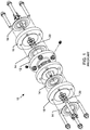
- FIGURE 1 shows an exploded view of a prior art cryogenic electrical power feed-through assembly 10.
- the feed-through assembly 10 provides an electrical path for conducting electrical power through a pressure boundary of an LNG (Liquid Nitrogen Gas) or other cryogenic fluids process or storage systems.
- a centrally located contact header assembly 12 has two main seals 14 that are compressed by a power-side flange 16 and a load-side flange 18. Each flange has conductive contact pins 20 sealed therein. The pins 20 are electrically connected inside the contact header assembly 12 such that power is transferred from the atmospheric side to the cryogenic side.
- the flanges 16 and 18 are of a standard size and shape. This is actually quite problematic as the proper orientation and assembly is not intuitive and fool-proof. It is very common for the flanges to be rotated incorrectly or to be attached incorrectly. In many shops and installation locations, similar flanges may be easily located on site. This allows an installer the availability of using non-compliant flange connection parts or to improperly assembly the components.
- the prior art design is susceptible to leaks and breakdown of the hermetic seals. A more robust design is necessary.
- the prior art designs are too large in size. This means they are overly heavy and hard to install. Fourth, there are no grounding lugs available on the prior art designs. Finally, there is no ingress protection for the connectors so possibility of sparking due to foreign material ingress exists despite proper electrical isolation.
- the present invention fulfills these needs and provides other related advantages.
- the contact header assembly of the invention is configured to be installed as part of a cryogenic electrical power feed-through assembly includes a feed-through body forming a feed-through body cavity disposed therethrough extending between a first opening end to a second opening end.
- a first contactor plate assembly includes a first contactor plate, a first plurality of insulative bushings hermetically sealed to and extending through the first contactor plate, and a first plurality of contact pins hermetically sealed to and extending through the first plurality of insulative bushings, wherein the first plurality of contact pins are electrically conductive and in non-conductive relation to the first contactor plate and feed-through body.
- a second contactor plate assembly includes a second contactor plate, a second plurality of insulative bushings hermetically sealed to and extending through the second contactor plate, a second plurality of contact pins hermetically sealed to and extending through the second plurality of insulative bushings, wherein the second plurality of contact pins are electrically conductive and in non-conductive relation to the second contactor plate.
- the first contactor plate assembly is disposed at and hermetically seals the first opening end of the feed-through body with a first electron beam weld formed between the first contactor plate and the first opening end.
- the second contactor plate assembly is disposed at and hermetically seals the second opening end of the feed-through body with a second electron beam weld formed between the second contactor plate and the second opening end.
- the first contactor plate assembly is completely disposed within the integrally formed first flange and the second contactor plate assembly is completely disposed within the integrally formed second flange.
- the feed-through body may include an integrally formed first flange disposed at the first opening end, and the feed-through body may further include an integrally formed second flange disposed at the second opening end.
- a first outwardly facing surface of the first contactor plate may include a first annular groove, the first annular groove encompassing the first plurality of insulative bushings and contact pins, and wherein a second outwardly facing surface of the second contactor plate may include a second annular groove, the second annular groove encompassing the second plurality of insulative bushings and contact pins.
- the first and second flanges may each include a plurality of fastener holes, wherein the plurality of fastener holes each have a female-thread.
- the first flange and second flange may each have an outer rectangular surface.
- the contact header assembly may include a load-side body forming a first cavity disposed therethrough extending between a first fitting end to a load-side flanged end, wherein the load-side flanged end of the load-side body is connected to the first flange of the feed-through body, and including a first seal disposed within the first annular groove, the first seal compressed between the first contactor plate and the load-side flanged end.
- the contact header assembly may include a power-side body forming a second cavity disposed therethrough extending between a second fitting end to a power-side flanged end, wherein the power-side flanged end of the power-side body is connected to the second flange of the feed-through body, and including a second seal disposed within the second annular groove, the second seal compressed between the second contactor plate and the power-side flanged end.
- the first fitting end or the second fitting end may be a weldneck fitting, a socket weld fitting or a female pipe fitting.
- the load-side flanged end may include a load-side plurality of fastener holes aligned to the plurality of fastener holes of the first flange of the feed-through body, and wherein the power-side flanged end has a power-side plurality of fastener holes aligned to the plurality of fastener holes of the second flange of the feed-through body.
- the load-side plurality of fastener holes and the power-side plurality of fastener holes may each have a female threaded portion adjacent to a female unthreaded portion.
- a load-side connector base may have at one end a first plurality of conductive pin receptacles configured to receive a portion of each of the first plurality of contact pins, where the first plurality of conductive pin receptacles are connectable to a load side conductor at the other end.
- a power-side connector base may have at one end a second plurality of conductive pin receptacles configured to receive a portion of each of the second plurality of contact pins, where the second plurality of conductive pin receptacles are connectable to a power side conductor at the other end.
- a first circumferential vapor seal may be between an outside surface of the load-side connector base and an inside surface of the load-side body, and including a second circumferential vapor seal between an outside surface of the power-side connector base and an inside surface of the power-side body.
- a first gasket may be between the load-side connector base and the first contactor plate, the first gasket comprising a plurality of holes configured to facilitate the first plurality of contact pins extending therethrough, wherein the first gasket is smaller in diameter in comparison to the first seal, and including a second gasket between the power-side connector base and the second contactor plate, the second gasket comprising a plurality of holes configured to facilitate the second plurality of contact pins extending therethrough, wherein the second gasket is smaller in diameter in comparison to the second seal.
- the first and second plurality of contact pins may extend beyond both sides of their respective first and second contactor plates.
- the first plurality of contact pins may be respectively aligned to the second plurality of contact pins.
- the first plurality of contact pins may be electrically coupled to the second plurality of contact pins.
- the contact header assembly may include a plurality of electrically conductive connectors, each connector having a first socket end opposite a second socket end, wherein the plurality of connectors electrically connect the plurality of first contact pins to the plurality of second contact pins.
- the first plurality of contact pins may be partially disposed respectively within the first socket ends and the second plurality of contact pins are partially disposed respectively within the second socket ends.
- the contact header assembly may include a plurality of insulative sleeves disposed around the plurality of connectors.
- the first and second flange may each have at least one anti-rotation pin feature, where the anti-rotation pin feature is non-symmetrically aligned with respect to the plurality of fastener holes.
- the contact header assembly may include a pressure valve disposed within the feed-through body in pressurized communication with the feed-through body cavity.
- the first plurality of insulative bushings may be glass bushings.
- the first flange, second flange, load-side flanged end and power-side flanged end may each have an outer rectangular surface.
- At least one side of each outer rectangular surface may include a repeated indicia that is aligned along a length of the cryogenic electrical power feed-through assembly.
- a plurality of fasteners may fasten the first flange to the load-side flanged end and fasten the second flange to the power-side flanged end, wherein the plurality of fasteners may be captive fasteners, the captive fasteners captured with respect to the load-side and power-side flanged ends.
- the first plurality of conductive pin receptacles may be epoxied within the load-side connector base, the first plurality of conductive pin receptacles in non-conductive relation to one another and to the load-side body.
- the second plurality of conductive pin receptacles may be epoxied within the power-side connector base, the second plurality of conductive pin receptacles in non-conductive relation to one another and to the power-side body.
- the first cavity of the load-side body may include a first abutment feature abutting against the other end of the load-side connector base biasing the load-side connector base towards the first contactor plate thereby compressing the first gasket.
- the second cavity of the power-side body may include a second abutment feature abutting against the other end of the power-side connector base biasing the power-side connector base towards the second contactor plate thereby compressing the second gasket.
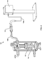
- FIGURE 2 is a perspective view of a cryogenic system 100.
- a cryogenic pump 102 is disposed within a cryogenic chamber 104. Power is provided to the pump 102 from a power supply box 106. From the power supply box 106 runs a power cable 108a. Electrical energy is provided from an atmospheric-side / power-side to inside the pump 102 on the load-side by passing electrical energy through the cryogenic electrical power feed-through assembly 110. On the load-side, the electrical energy flows through another power cable 108b to the pump 102.
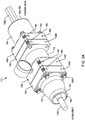
- FIGURE 3A is a perspective view of an exemplary embodiment of a cryogenic electrical power feed-through assembly 110.
- the feed-through assembly 110 can be subdivided into a contact header assembly 112, a load-side body 114 and a power-side body 116, where the load-side body 114 and power-side body 116 are attached to the contact header assembly 112.
- a feed-through body 118 has a feed-through body cavity 120 disposed therethrough extending between a first opening end 122 to a second opening end 124.
- the feed-through body 118 comprises an integrally formed first flange 126 disposed at the first opening end 122 and an integrally formed second flange 128 disposed at the second opening end 124.
- the first and second flanges each comprise a plurality of fastener holes 130.
- the plurality of fastener holes 130 each comprise a female-thread such that a fastener 152 may be fixedly attached.
- the feed-through body may be made from a variety of materials.
- materials can include, but are not limited to, SS 316L, SS304, UNS S32205/S31803, S32750 or any other cryogenic & marine suitable materials.
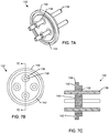
- a contactor plate assembly 132 comprises a contactor plate 134 with a first plurality of insulative bushings 136 hermetically sealed to and extending through the first contactor plate 134.
- the insulative bushings are electrically non-conductive and can be made from glass or other insulative materials.
- a plurality of contact pins 138 are hermetically sealed to and extending through the first plurality of glass bushings 136.
- the plurality of contact pins 138 are electrically conductive and in non-conductive relation to the contactor plate 134 and feed-through body 118.
- the contact pins 138 can be made from, but are not limited to, copper cored nickel-iron alloy, gold plated or silver plated, or any other materials with good conductive properties combined with good strength at cryogenic conditions. Additional criteria for the pin material is so that the dimensional changes caused by temperature changes do not affect the fits with the glass sleeve.
- An outwardly facing surface 140 of the contactor plate 134 comprises an annular groove 142.
- the annular groove 142 is larger in diameter and encompasses the plurality of glass bushings 136 and contact pins 138.
- first contactor plate assembly 132a and a second contact plate assembly 132b there is shown a first contactor plate assembly 132a and a second contact plate assembly 132b.
- first and second plurality of contact pins 138a and 138b extend beyond both sides of their respective first and second contactor plates 134a and 134b.
- first plurality of contact pins 138a are respectively aligned to the second plurality of contact pins 138b.
- the first plurality of contact pins 138a are electrically coupled to the second plurality of contact pins 138b. This is accomplished with the use of a plurality of electrically conductive connectors 144, as best shown in FIGURES 8A-B .
- Each connector 144 comprises a first socket end 146a opposite a second socket end 146b.
- the plurality of connectors 144 electrically connect the plurality of first contact pins 138a to the plurality of second contact pins 138b.
- the first plurality of contact pins 138a are partially disposed respectively within the first socket ends 146a and the second plurality of contact pins 138b are partially disposed respectively within the second socket ends 146b.
- the connectors 144 may be made from, but are not limited to, copper alloys which can then be gold plated or silver plated, or any other materials with good conductive properties combined with good strength at cryogenic conditions.
- a plurality of insulative sleeves 148 from FIGURES 10A-B are disposed around the plurality of connectors 144.
- the insulative sleeves are hollow in the center and contain the connectors 144 within.
- the insulative sleeves may be made from, but are not limited to, Nomex, G10, or other materials may be used which have dielectric strength of more than 0.2 kV/mm & are suitable for operating conditions below -20 degrees Celsius.
- the first contactor plate assembly 132 is disposed at and hermetically seals the first opening end 122 of the feed-through body 118 with a first electron beam weld 150a between the first contactor plate 134 and the first opening end 122.
- the second contactor plate assembly 132 is disposed at and hermetically seals the second opening end 124 of the feed-through body 118 with a second electron beam weld 150b between the second contactor plate and the second opening end.
- a weld 150 is much stronger and more reliable once formed.
- the contact header assembly 112 is completed.
- Other types of suitable welds are may be used such as laser welds.
- FIGURES 4A-C show another embodiment of a cryogenic electrical power feed-through assembly.
- a load-side body 114 forms a first cavity 154 disposed therethrough extending between a first fitting end 156 to a load-side flanged end 158.
- the load-side flanged end 158 of the load-side body 114 is connected to the first flange 126 of the feed-through body 118.
- the load-side flanged end 158 comprises a load-side plurality of fastener holes 170a aligned to the plurality of fastener holes of the first flange of the feed-through body.
- a first seal 160a is disposed within the first annular groove 142.
- the first seal 160a is compressed between the first contactor plate 134a and the load-side flanged end 158.
- the first seal 160a may be an o-ring type seal.
- Other types of seal that could be used include energized seals.
- a connector base 172 has been removed from the load-side such that it is easier to view the structure within the load-side body 114.
- a power-side body 116 forms a second cavity 164 disposed therethrough extending between a second fitting end 166 to a power-side flanged end 168.
- the power-side flanged end 168 of the power-side body 116 is connected to the second flange 128 of the feed-through body 118.
- the power-side flanged end 168 comprises a power-side plurality of fastener holes 170b aligned to the plurality of fastener holes of the second flange 128 of the feed-through body 118.
- a second seal 160b is disposed within the second annular groove 142, where the second seal 160b is compressed between the second contactor plate 134b and the power-side flanged end 168.
- the load-side body 114 is different than the power-side body 118.
- the load-side body 114 shown here is a weldneck fitting type.
- the power-side body 118 shown here is a female pipe fitting type or a socket weld fitting type.
- the load-side and power-side fittings could be of the same type.
- a load-side connector base 172a has at one end 174 a first plurality of conductive pin receptacles 176 configured to receive the first plurality of contact pins.
- the first plurality of conductive pin receptacles 176 are connectable to a load side conductor 108b at the other end 178.
- a first circumferential vapor seal 180 is between an outside surface 182 of the load-side connector base 174 and an inside surface 184 of the load-side body. As shown herein, the outside surface of the load-side connector base is a circumferential groove 182.
- a power-side connector base has the same construction as the load-side connector base.
- the load-side and power-side connector bases are pushed into contact by an abutment feature 186.
- the abutment feature 186 is a step or smaller diameter surface that is smaller in diameter or size as compared to the connector base 172. In this way the abutment feature 186 forces the connector base 172 into position.
- the plurality of conductive pin receptacles 176 may be epoxied within the connector base 174. This prevents cryogenic fluid from passing through small gaps between the pin receptacles 176 and the connector base 174.
- the first flange 126, second flange 128, load-side flange end 158 and the power-side flange end 168 each comprise an outer rectangular (square) surface. Having the flanges shaped into rectangular surfaces helps to properly align them during assembly and also prevents other common flanges that may be in the vicinity from being used. This means the flanges are each a non-standard ANSI-type flange. This prevents common ANSI-type flanges from being used to connect up to the embodiments disclosed herein.
- each outer rectangular surface may include a repeated indicia 188 that is aligned along a length of the cryogenic electrical power feed-through assembly.
- the indicia 188 shown here are the numerals 1, 2, 3 and 4. However, other words or numbers may be used.
- the indicia 188 allows a technician to quickly visually verify that all the parts are properly connected.
- the indicia can be color coded portions 190. For example, the color red, blue, green, brown or any other color or combination can be used so that it is easy for a technician to visually identify whether the assembly is correct or incorrect.
- the first and second flange each may include at least one anti-rotation pin feature, where the anti-rotation pin feature is non-symmetrically aligned with respect to the plurality of fastener holes. This means that if the orientation was not proper, the first flange 126 would not be able to mate up to the load-side flange end 166. The parts would simply not go together.
- This anti-rotation pin feature 192 can also be used between the load-side and power-side bodies and the connector base 172. The pin 192 prevents rotation of the connector base 172 relative to the load-side and power-side bodies.
- a first gasket 194a is between the load-side connector base and the first contactor plate.
- the first gasket 194a comprises a plurality of holes configured to facilitate the first plurality of contact pins extending through.
- the first gasket 194 is smaller in diameter in comparison to the first seal.
- a second gasket 194b is between the power-side connector base and the second contactor plate.
- a pressure valve 196 is disposed within the feed-through body in pressurized communication with the feed-through body cavity.
- the pressure valve 196 may be other types of valves as well.
- a Schrader valve 198 may also be disposed within the feed-through body in pressurized communication with the feed-through body cavity
- the plurality of fasteners 152 fastening the first flange to the load-side flanged end and fastening the second flange to the power-side flanged end may be captive fasteners.
- the captive fasteners are captured with respect to the load-side and power-side flanged ends such that they are not lost or that a technician attempts to install non-compliant fasteners.
- the fasteners 152 may have a distal threaded end with a proximal unthreaded portion, such that the fasteners 152 are captured within the load-side and power-side flanged ends.
- the electrical power feed-through of the present invention provides an electrical path for conducting electrical power through the pressure boundary of an LNG (Liquid Nitrogen Gas) or other cryogenic fluids process or storage system.
- LNG Liquid Nitrogen Gas
- the electrical power feed-through prevents leakage of LNG or other cryogenic fluids or vapors thereof from a pressurized process or storage system to the atmosphere, and to prevent the ingress of air into a low pressure vapor space in a cryogenic system, thereby avoiding a potentially flammable or explosive atmosphere.
- the electrical power feed-through may embody the following features: (1) an electrical connector that serves as a thermal barrier to limit the heat inleak from the ambient atmosphere to the cryogenic process; (2) an electrical connector that incorporates a vapor seal that prevents the transmission of LNG vapor from the process load side to the ambient atmosphere or to the process side terminal header; (3) an electrical connector that incorporates a plurality of terminal pin sockets that each embody a barrier and are sealed within a barrier compound that prevents the leakage of fluid through the cables into the process side terminal header; (4) a stainless body through a cylindrical bore at each end of which is a counterbore into which is fitted; a stainless steel process side terminal header into and through which a plurality of terminal pins, normally three or four depending upon on the number of electrical circuits to be fed through, each of which is bonded to and electrically isolated from one another and from the terminal header, by an individual or common glass insulator, the arrangement of the bonded glass insulator serves also to seal one side of the terminal header; a similar stainless steel power system side terminal
- Each of the terminal headers is electron beam seal welded into the body of the dual process seal feedthrough whereas the previous art depends on a gasket or O-ring to prevent leak of the pressure barrier gas.
- Such gas leakage can result in spurious alarms indicating seal failure, and can result in the ultimate loss of the barrier gas, potentially allowing the process gas into the isolation chamber.
- the present invention embodies additional dual o-ring seals on the process side that act as preventative seal to reduce the prospect of process gas to the surrounding ambient area, (potentially creating an explosive atmosphere) and preventing the process gas from reaching the terminal pin seals.
- the wire connection sockets that engage the terminal pins are sealed in a manner that prevents the infiltration of process gas along the interstices in the cable lay, into the terminal header area of the load side terminal pin seals.
- CN 103 618 156 A describes a contact header assembly configured to be installed as part of a cryogenic electrical power feed-through assembly with a first contactor plate having a threaded hole or a through hole for using a fastener to attach it to either the power-side or the load-side.
- This first contactor plate has the same diameter and/or width as the first and second flanges on the feed-through body. There is no threaded hole or through hole in the first and second integrally formed flanges in the device according to CN 103 618 156 A .
- CN 103 618 156 A also fails to teach a first and second contractor plate assemblies being disposed within their respective integrally formed first and second flanges. Additionally, CN 103 618 156 A neither shows nor teaches a contact header assembly in which the first and second flanges each comprise a plurality of fastener holes.
Landscapes
- Physics & Mathematics (AREA)
- Condensed Matter Physics & Semiconductors (AREA)
- General Physics & Mathematics (AREA)
- Engineering & Computer Science (AREA)
- Architecture (AREA)
- Civil Engineering (AREA)
- Structural Engineering (AREA)
- Connector Housings Or Holding Contact Members (AREA)
- Gas Or Oil Filled Cable Accessories (AREA)
- Microelectronics & Electronic Packaging (AREA)
Claims (16)
- Ensemble de tête de contact (112) configuré pour être installé en tant que partie d'un ensemble d'alimentation par traversée en énergie électrique cryogénique (100), l'ensemble de tête de contact (112) comprenant :a) un corps d'alimentation par traversée (118) qui comporte une cavité de corps d'alimentation par traversée (120) qui est disposée de sorte qu'elle s'étend au travers entre une première extrémité d'ouverture (122) et une seconde extrémité d'ouverture (124), dans lequel le corps d'alimentation par traversée (118) inclut une première bride formée d'un seul tenant (126) qui est disposée au niveau de la première extrémité d'ouverture (122), et le corps d'alimentation par traversée (118) inclut en outre une seconde bride formée d'un seul tenant (128) qui est disposée au niveau de la seconde extrémité d'ouverture (124) ;b) un premier ensemble de plaque de contacteur (132a) comprenant :i) une première plaque de contacteur (134a) ;ii) une première pluralité de douilles isolantes (136) qui sont scellées hermétiquement sur la première plaque de contacteur (134a) et qui s'étendent au travers de celle-ci ; etiii) une première pluralité de broches de contact (138a) qui sont scellées hermétiquement sur les douilles isolantes de la première pluralité de douilles isolantes (136) et qui s'étendent au travers de celles-ci ; dans lequel :
les broches de contact de la première pluralité de broches de contact (138a) sont électriquement conductrices et sont selon une relation non conductrice par rapport à la première plaque de contacteur (134a) et par rapport au corps d'alimentation par traversée (118) ;c) un second ensemble de plaque de contacteur (132b) comprenant :i) une seconde plaque de contacteur (134b) ;ii) une seconde pluralité de douilles isolantes (136) qui sont scellées hermétiquement sur la seconde plaque de contacteur (134b) et qui s'étendent au travers de celle-ci ; etiii) une seconde pluralité de broches de contact (138b) qui sont scellées hermétiquement sur les douilles isolantes de la seconde pluralité de douilles isolantes (136) et qui s'étendent au travers de celles-ci ; dans lequel :
les broches de contact de la seconde pluralité de broches de contact sont électriquement conductrices et sont selon une relation non conductrice par rapport à la seconde plaque de contacteur (134b) ; dans lequel :d) le premier ensemble de plaque de contacteur (132a) est disposé au niveau de la première extrémité d'ouverture (122) du corps d'alimentation par traversée (118) et il est scellé hermétiquement sur celle-ci à l'aide d'une première soudure par faisceau électronique (150a) qui est formée entre la première plaque de contacteur (134a) et la première extrémité d'ouverture (122) ; et dans lequel :e) le second ensemble de plaque de contacteur (132b) est disposé au niveau de la seconde extrémité d'ouverture (124) du corps d'alimentation par traversée (118) et il est scellé hermétiquement sur celle-ci à l'aide d'une seconde soudure par faisceau électronique (150b) qui est formée entre la seconde plaque de contacteur et la seconde extrémité d'ouverture (124) ;
caractérisé en ce que :le premier ensemble de plaque de contacteur (132a) est disposé complètement à l'intérieur de la première bride formée d'un seul tenant (126) ; et en ce que :le second ensemble de plaque de contacteur (132b) est disposé complètement à l'intérieur de la seconde bride formée d'un seul tenant (128). - Ensemble de tête de contact (112) selon la revendication 1, dans lequel une première surface faisant face vers l'extérieur de la première plaque de contacteur (134a) comprend une première gorge annulaire (142), la première gorge annulaire (142) englobant la première pluralité de douilles isolantes (136) et la première pluralité de broches de contact (138a), et dans lequel une seconde surface faisant face vers l'extérieur de la seconde plaque de contacteur (134b) comprend une seconde gorge annulaire (142), la seconde gorge annulaire (142) englobant la seconde pluralité de douilles isolantes (136) et la seconde pluralité de broches de contact (138b).
- Ensemble de tête de contact (112) selon la revendication 2, incluant un corps de côté de charge (114) qui forme une première cavité (154) qui est disposée de sorte qu'elle s'étend au travers entre une première extrémité de raccord (156) et une extrémité bridée de côté de charge (158), dans lequel l'extrémité bridée de côté de charge (158) du corps de côté de charge (114) est connectée à la première bride (126) du corps d'alimentation par traversée (118), et incluant un premier joint d'étanchéité (160a) qui est disposé à l'intérieur de la première gorge annulaire (142), le premier joint d'étanchéité étant comprimé entre la première plaque de contacteur (134a) et l'extrémité bridée de côté de charge (158).
- Ensemble de tête de contact (112) selon la revendication 3, incluant un corps de côté d'alimentation en énergie électrique (116) qui forme une seconde cavité (164) qui est disposée de sorte qu'elle s'étend au travers entre une seconde extrémité de raccord (166) et une extrémité bridée de côté d'alimentation en énergie électrique (168), dans lequel l'extrémité bridée de côté d'alimentation en énergie électrique (168) du corps de côté d'alimentation en énergie électrique (116) est connectée à la seconde bride (128) du corps d'alimentation par traversée (118), et incluant un second joint d'étanchéité (160b) qui est disposé à l'intérieur de la seconde gorge annulaire (142), le second joint d'étanchéité (160b) étant comprimé entre la seconde plaque de contacteur (134b) et l'extrémité bridée de côté d'alimentation en énergie électrique (168).
- Ensemble de tête de contact (112) selon la revendication 4, dans lequel les première (126) et seconde (128) brides comprennent chacune une pluralité de trous de moyen de fixation (130), dans lequel les trous de moyen de fixation de la pluralité de trous de moyen de fixation (130) comprennent chacun un filetage femelle, et dans lequel la première bride (126) et la seconde bride (128) comprennent chacune une surface rectangulaire externe.
- Ensemble de tête de contact (112) selon la revendication 5, dans lequel la première extrémité de raccord (156) ou la seconde extrémité de raccord (166) comprend un raccord à soudage de col, un raccord à soudage de tubulure ou un raccord à tuyau femelle.
- Ensemble de tête de contact (112) selon la revendication 5, dans lequel l'extrémité bridée de côté de charge (158) comprend des trous de moyen de fixation d'une pluralité de trous de moyen de fixation de côté de charge (170a) qui sont alignés par rapport aux trous de moyen de fixation de la pluralité de trous de moyen de fixation (130) de la première bride (126) du corps d'alimentation par traversée (118), et dans lequel l'extrémité bridée de côté d'alimentation en énergie électrique (168) comprend des trous de moyen de fixation d'une pluralité de trous de moyen de fixation de côté d'alimentation en énergie électrique (170b) qui sont alignés par rapport aux trous de moyen de fixation de la pluralité de trous de moyen de fixation (130) de la seconde bride (128) du corps d'alimentation par traversée (118), dans lequel les trous de moyen de fixation de la pluralité de trous de moyen de fixation de côté de charge (170a) et les trous de moyen de fixation de la pluralité de trous de moyen de fixation de côté d'alimentation en énergie électrique (170b) comprennent chacun une partie filetée femelle qui est adjacente à une partie non filetée femelle.
- Ensemble de tête de contact (112) selon la revendication 5, incluant une base de connecteur de côté de charge (172a) qui comporte, au niveau d'une extrémité (174), une première pluralité de réceptacles de broche conducteurs (176) qui sont configurés de manière à ce qu'ils reçoivent une partie de chaque broche de contact de la première pluralité de broches de contact (138a), dans lequel les réceptacles de broche conducteurs de la première pluralité de réceptacles de broche conducteurs (176) peuvent être connectés à un conducteur de côté de charge (108b) au niveau de l'autre extrémité (178), incluant une base de connecteur de côté d'alimentation en énergie électrique (172b) qui comporte, au niveau d'une extrémité (174), une seconde pluralité de réceptacles de broche conducteurs (176) qui sont configurés de manière à ce qu'ils reçoivent une partie de chaque broche de contact de la seconde pluralité de broches de contact (138b), dans lequel les réceptacles de broche conducteurs de la seconde pluralité de réceptacles de broche conducteurs (176) peuvent être connectés à un conducteur de côté d'alimentation en énergie électrique (108a) au niveau de l'autre extrémité, incluant un premier joint d'étanchéité à la vapeur circonférentiel (180) entre une surface externe (182) de la base de connecteur de côté de charge (172a) et une surface interne (184) du corps de côté de charge (114), incluant un second joint d'étanchéité à la vapeur circonférentiel (180) entre une surface externe (182) de la base de connecteur de côté d'alimentation en énergie électrique (172b) et une surface interne (184) du corps de côté d'alimentation en énergie électrique (116), et incluant une première garniture d'étanchéité (194a) entre la base de connecteur de côté de charge (172a) et la première plaque de contacteur, la première garniture d'étanchéité (194a) comprenant une pluralité de trous qui sont configurés de manière à ce qu'ils facilitent l'extension au travers de la première pluralité de broches de contact (138a), dans lequel la première garniture d'étanchéité présente un diamètre plus petit par comparaison avec le premier joint d'étanchéité, et incluant une seconde garniture d'étanchéité (194b) entre la base de connecteur de côté d'alimentation en énergie électrique (172b) et la seconde plaque de contacteur, la seconde garniture d'étanchéité (194b) comprenant une pluralité de trous qui sont configurés de manière à ce qu'ils facilitent l'extension au travers de la seconde pluralité de broches de contact, dans lequel la seconde garniture d'étanchéité présente un diamètre plus petit par comparaison avec le second joint d'étanchéité (160b).
- Ensemble de tête de contact (112) selon la revendication 8, dans lequel les réceptacles de broche de la première pluralité de réceptacles de broche conducteurs (176) sont fixés par époxy à l'intérieur de la base de connecteur de côté de charge (172a), les réceptacles de broche de la première pluralité de réceptacles de broche conducteurs (176) étant selon une relation non conductrice les uns par rapport aux autres et par rapport au corps de côté de charge (114), dans lequel les réceptacles de broche de la seconde pluralité de réceptacles de broche conducteurs (176) sont fixées par époxy à l'intérieur de la base de connecteur de côté d'alimentation en énergie électrique (172b), les réceptacles de broche de la seconde pluralité de réceptacles de broche conducteurs (176) étant selon une relation non conductrice les uns par rapport aux autres et par rapport au corps de côté d'alimentation en énergie électrique (116).
- Ensemble de tête de contact (112) selon la revendication 8, dans lequel la première cavité du corps de côté de charge (114) inclut une première caractéristique de butée (186) qui vient en butée contre l'autre extrémité de la base de connecteur de côté de charge (172a) en sollicitant par poussée la base de connecteur de côté de charge (172a) en direction de la première plaque de contacteur (134a), d'où ainsi la compression de la première garniture d'étanchéité (194a), dans lequel la seconde cavité (164) du corps de côté d'alimentation en énergie électrique (116) inclut une seconde caractéristique de butée (186) qui vient en butée contre l'autre extrémité de la base de connecteur de côté d'alimentation en énergie électrique (172b) en sollicitant par poussée la base de connecteur de côté d'alimentation en énergie électrique (172b) en direction de la seconde plaque de contacteur (134b), d'où ainsi la compression de la seconde garniture d'étanchéité (194b).
- Ensemble de tête de contact (112) selon la revendication 5, dans lequel la première bride (126), la seconde bride (128), l'extrémité bridée de côté de charge (158) et l'extrémité bridée de côté d'alimentation en énergie électrique (168) comprennent chacune une surface rectangulaire externe, dans lequel au moins un côté de chaque surface rectangulaire externe comprend une information répétée (188) qui est alignée suivant une longueur de l'ensemble d'alimentation par traversée en énergie électrique cryogénique (100), dans lequel la première bride (126), la seconde bride (128), l'extrémité bridée de côté de charge (158) et l'extrémité bridée de côté d'alimentation en énergie électrique (168) comprennent chacune une bride du type ANSI non standard, incluant une pluralité de moyens de fixation (152) qui fixent la première bride (126) sur l'extrémité bridée de côté de charge (158) et qui fixent la seconde bride (128) sur l'extrémité bridée de côté d'alimentation en énergie électrique (168), dans lequel les moyens de fixation de la pluralité de moyens de fixation (152) comprennent des moyens de fixation captifs, les moyens de fixation captifs étant capturés par rapport à l'extrémité bridée de côté de charge (158) et par rapport à l'extrémité bridée de côté d'alimentation en énergie électrique (168), dans lequel l'information répétée est un chiffre répété, un mot répété ou une partie codée en couleur répétée.
- Ensemble de tête de contact (112) selon la revendication 1, dans lequel la première pluralité de broches de contact (138a) et la seconde pluralité de broches de contact (138b) s'étendent au-delà de deux côtés de leurs première et seconde plaques de contacteur respectives, dans lequel les broches de contact de la première pluralité de broches de contact (138a) sont respectivement alignées par rapport aux broches de contact de la seconde pluralité de broches de contact (138b), dans lequel les broches de contact de la première pluralité de broches de contact (138a) sont couplées électriquement aux broches de contact de la seconde pluralité de broches de contact (138b).
- Ensemble de tête de contact (112) selon la revendication 1, incluant une pluralité de connecteurs électriquement conducteurs (144), chaque connecteur comprenant une première extrémité tubulaire (146a) qui est opposée à une seconde extrémité tubulaire (146b), dans lequel les connecteurs de la pluralité de connecteurs (144) connectent électriquement les broches de contact de la pluralité de premières broches de contact (138a) aux broches de contact de la pluralité de secondes broches de contact (138b), dans lequel les broches de contact de la première pluralité de broches de contact (138a) sont respectivement disposées partiellement à l'intérieur des premières extrémités tubulaires (146a) et les broches de contact de la seconde pluralité de broches de contact (138b) sont respectivement disposées partiellement à l'intérieur des secondes extrémités tubulaires (146b), incluant une pluralité de gaines isolantes (148) qui sont disposées autour de la pluralité de connecteurs (144).
- Ensemble de tête de contact (112) selon la revendication 1, dans lequel la première bride (126) et la seconde bride (128) comprennent chacune au moins une caractéristique de broche anti-rotation (192), dans lequel la caractéristique de broche anti-rotation (192) est alignée de façon non symétrique par rapport à la pluralité de trous de moyen de fixation (130).
- Ensemble de tête de contact (112) selon la revendication 1, incluant une soupape de sécurité (196) qui est disposée à l'intérieur du corps d'alimentation par traversée (118) selon une communication sous pression avec la cavité de corps d'alimentation par traversée (120), et dans lequel les douilles isolantes de la première pluralité de douilles isolantes (136) comprennent des douilles en verre.
- Ensemble de tête de contact (112) selon la revendication 1, dans lequel la première bride (126) et la seconde bride (128) comprennent chacune une pluralité de trous de moyen de fixation (130).
Applications Claiming Priority (2)
| Application Number | Priority Date | Filing Date | Title |
|---|---|---|---|
| US201461981133P | 2014-04-17 | 2014-04-17 | |
| PCT/US2015/026541 WO2015161298A1 (fr) | 2014-04-17 | 2015-04-17 | Traversée électrique cryogénique |
Publications (3)
| Publication Number | Publication Date |
|---|---|
| EP3132177A1 EP3132177A1 (fr) | 2017-02-22 |
| EP3132177A4 EP3132177A4 (fr) | 2018-01-31 |
| EP3132177B1 true EP3132177B1 (fr) | 2020-03-25 |
Family
ID=54323239
Family Applications (1)
| Application Number | Title | Priority Date | Filing Date |
|---|---|---|---|
| EP15779567.5A Active EP3132177B1 (fr) | 2014-04-17 | 2015-04-17 | Traversée électrique cryogénique |
Country Status (7)
| Country | Link |
|---|---|
| US (1) | US9478965B2 (fr) |
| EP (1) | EP3132177B1 (fr) |
| JP (1) | JP6571758B2 (fr) |
| KR (1) | KR102176848B1 (fr) |
| CN (1) | CN106574746B (fr) |
| RU (1) | RU2622033C1 (fr) |
| WO (1) | WO2015161298A1 (fr) |
Families Citing this family (8)
| Publication number | Priority date | Publication date | Assignee | Title |
|---|---|---|---|---|
| US20160083119A1 (en) * | 2014-05-02 | 2016-03-24 | Craig Davidson | Thrust Augmentation Systems |
| KR200491181Y1 (ko) | 2018-06-26 | 2020-02-28 | 주식회사 한국가스기술공사 | 피드스루 |
| US11688967B2 (en) | 2019-11-21 | 2023-06-27 | KYOCERA AVX Components Corporation | Wire termination device for coupling a wire to a feedthrough device and system including the same |
| CN113531220A (zh) * | 2020-04-15 | 2021-10-22 | 康普技术有限责任公司 | 缆线密封装置和缆线密封系统 |
| CN112530724B (zh) * | 2020-10-19 | 2023-09-08 | 陕西斯瑞新材料股份有限公司 | 一种利用钨粉制造电子束焊接铜钨触片的方法 |
| US20240392787A1 (en) | 2023-05-25 | 2024-11-28 | Dwc & Associates, Llc | Inducers for cryogenic pumps and related systems and methods |
| US12584488B2 (en) | 2024-05-24 | 2026-03-24 | Flowserve Us Company | Balance drums and systems for managing axial forces for pumps and related systems and methods |
| US12129929B1 (en) * | 2024-06-03 | 2024-10-29 | Marco Daniel Iseli | Universal multiple instrumentation gland |
Family Cites Families (10)
| Publication number | Priority date | Publication date | Assignee | Title |
|---|---|---|---|---|
| BE788766A (fr) * | 1971-09-23 | 1973-01-02 | Bunker Ramo | Assemblages de traversee electriques |
| US4213004A (en) * | 1978-06-30 | 1980-07-15 | The United States Of America As Represented By The Secretary Of The Air Force | Hermetic electrical feedthrough for aluminum housing and method of making same |
| JPH0237259Y2 (fr) * | 1986-09-24 | 1990-10-09 | ||
| DE19728370A1 (de) * | 1997-07-03 | 1999-01-07 | Bosch Gmbh Robert | Kabeldurchführung für Anschlußkabel eines Gasmeßfühlers |
| NL1015895C2 (nl) * | 2000-08-08 | 2002-02-12 | Beele Eng Bv | Doorvoerinrichting. |
| EP2031288B1 (fr) * | 2006-06-07 | 2010-07-14 | Furukawa Electric Industrial Cable Co., Ltd. | Trou d'interconnexion et traversee |
| US7939769B2 (en) * | 2006-11-27 | 2011-05-10 | Jetseal, Inc. | Sensor pass through assembly |
| CN102723150B (zh) * | 2012-07-09 | 2014-01-22 | 哈尔滨工业大学 | 一种低温绝缘子及其制作方法 |
| CN103345949B (zh) * | 2013-07-05 | 2015-10-28 | 清华大学 | 金属陶瓷烧结高温高压电气贯穿件 |
| CN103618156A (zh) * | 2013-12-26 | 2014-03-05 | 大连深蓝泵业有限公司 | 陶瓷焊接电气贯穿接头 |
-
2015
- 2015-04-17 US US14/690,250 patent/US9478965B2/en active Active
- 2015-04-17 RU RU2016144730A patent/RU2622033C1/ru active
- 2015-04-17 JP JP2017506644A patent/JP6571758B2/ja active Active
- 2015-04-17 CN CN201580020317.4A patent/CN106574746B/zh active Active
- 2015-04-17 WO PCT/US2015/026541 patent/WO2015161298A1/fr not_active Ceased
- 2015-04-17 KR KR1020167031946A patent/KR102176848B1/ko active Active
- 2015-04-17 EP EP15779567.5A patent/EP3132177B1/fr active Active
Non-Patent Citations (1)
| Title |
|---|
| None * |
Also Published As
| Publication number | Publication date |
|---|---|
| US20150305187A1 (en) | 2015-10-22 |
| US9478965B2 (en) | 2016-10-25 |
| JP2017521845A (ja) | 2017-08-03 |
| CN106574746B (zh) | 2020-03-27 |
| EP3132177A1 (fr) | 2017-02-22 |
| RU2622033C1 (ru) | 2017-06-09 |
| KR102176848B1 (ko) | 2020-11-10 |
| WO2015161298A1 (fr) | 2015-10-22 |
| JP6571758B2 (ja) | 2019-09-04 |
| CN106574746A (zh) | 2017-04-19 |
| KR20160145157A (ko) | 2016-12-19 |
| EP3132177A4 (fr) | 2018-01-31 |
Similar Documents
| Publication | Publication Date | Title |
|---|---|---|
| EP3132177B1 (fr) | Traversée électrique cryogénique | |
| US5626190A (en) | Apparatus for protecting electrical connection from moisture in a hazardous area adjacent a wellhead barrier for an underground well | |
| US5667008A (en) | Seal electrical conductor arrangement for use with a well bore in hazardous areas | |
| US6227908B1 (en) | Electric connection | |
| EP3394933B1 (fr) | Traversée électrique modulaire | |
| US9774131B2 (en) | Fire-resistant electrical feedthrough | |
| US8137136B1 (en) | Electrical disconnect for hazardous areas | |
| MXPA03011568A (es) | Desconexion y sellado rapidos de instrumento a prueba de explosiones. | |
| US8629367B2 (en) | Plug-in primary power connections of two modules of a gas-insulated high-voltage switchgear assembly | |
| EP0811265B1 (fr) | Procede d'installation d'un systeme de barres omnibus et systeme de barres omnibus | |
| KR101263411B1 (ko) | 가스로 절연된 고전압 측정 유닛 | |
| CN103762436A (zh) | 用于连接高压电缆的插座、插头及插拔器 | |
| US9070997B2 (en) | Mining cable couplers | |
| HK1236600B (en) | Cryogenic electrical feed-through | |
| HK1236600A1 (en) | Cryogenic electrical feed-through | |
| EP2654133A1 (fr) | Dispositif de connexion entre des appareils électriques haute tension | |
| KR102753657B1 (ko) | 부싱간 안전 이격 거리 확보를 위한 연장형 어댑터 및 이의 설치 방법 | |
| CA2281958C (fr) | Joint d'etancheite du type ferrule pour conduit electrique dans une barriere de tete de puits | |
| WO1994025726A1 (fr) | Agencement etanche de conducteurs electriques destine aux forages en atmosphere explosive dangereuse | |
| CN118414756A (zh) | 电缆模块、气体绝缘设备以及用于制造电缆模块的方法 | |
| WO2024258291A1 (fr) | Ensemble sous-marin haute tension | |
| GB2214726A (en) | Electrical adaptor | |
| WO2006094317A1 (fr) | Cables proteges |
Legal Events
| Date | Code | Title | Description |
|---|---|---|---|
| STAA | Information on the status of an ep patent application or granted ep patent |
Free format text: STATUS: THE INTERNATIONAL PUBLICATION HAS BEEN MADE |
|
| PUAI | Public reference made under article 153(3) epc to a published international application that has entered the european phase |
Free format text: ORIGINAL CODE: 0009012 |
|
| STAA | Information on the status of an ep patent application or granted ep patent |
Free format text: STATUS: REQUEST FOR EXAMINATION WAS MADE |
|
| 17P | Request for examination filed |
Effective date: 20161117 |
|
| AK | Designated contracting states |
Kind code of ref document: A1 Designated state(s): AL AT BE BG CH CY CZ DE DK EE ES FI FR GB GR HR HU IE IS IT LI LT LU LV MC MK MT NL NO PL PT RO RS SE SI SK SM TR |
|
| AX | Request for extension of the european patent |
Extension state: BA ME |
|
| DAV | Request for validation of the european patent (deleted) | ||
| DAX | Request for extension of the european patent (deleted) | ||
| RAP1 | Party data changed (applicant data changed or rights of an application transferred) |
Owner name: ACD, LLC |
|
| RIN1 | Information on inventor provided before grant (corrected) |
Inventor name: ACD, LLC |
|
| RIN1 | Information on inventor provided before grant (corrected) |
Inventor name: GEIPEL, MARK Inventor name: JOSHI, RAHUL Inventor name: CHALMERS, DENNIS W |
|
| RIC1 | Information provided on ipc code assigned before grant |
Ipc: H01B 17/06 20060101ALI20171221BHEP Ipc: F17C 13/00 20060101AFI20171221BHEP Ipc: H01R 4/68 20060101ALI20171221BHEP Ipc: H02G 15/34 20060101ALI20171221BHEP Ipc: H01B 11/00 20060101ALI20171221BHEP |
|
| A4 | Supplementary search report drawn up and despatched |
Effective date: 20180105 |
|
| REG | Reference to a national code |
Ref country code: HK Ref legal event code: DE Ref document number: 1236600 Country of ref document: HK |
|
| STAA | Information on the status of an ep patent application or granted ep patent |
Free format text: STATUS: EXAMINATION IS IN PROGRESS |
|
| 17Q | First examination report despatched |
Effective date: 20190305 |
|
| GRAP | Despatch of communication of intention to grant a patent |
Free format text: ORIGINAL CODE: EPIDOSNIGR1 |
|
| STAA | Information on the status of an ep patent application or granted ep patent |
Free format text: STATUS: GRANT OF PATENT IS INTENDED |
|
| INTG | Intention to grant announced |
Effective date: 20191021 |
|
| GRAS | Grant fee paid |
Free format text: ORIGINAL CODE: EPIDOSNIGR3 |
|
| GRAA | (expected) grant |
Free format text: ORIGINAL CODE: 0009210 |
|
| STAA | Information on the status of an ep patent application or granted ep patent |
Free format text: STATUS: THE PATENT HAS BEEN GRANTED |
|
| AK | Designated contracting states |
Kind code of ref document: B1 Designated state(s): AL AT BE BG CH CY CZ DE DK EE ES FI FR GB GR HR HU IE IS IT LI LT LU LV MC MK MT NL NO PL PT RO RS SE SI SK SM TR |
|
| REG | Reference to a national code |
Ref country code: GB Ref legal event code: FG4D |
|
| REG | Reference to a national code |
Ref country code: AT Ref legal event code: REF Ref document number: 1248957 Country of ref document: AT Kind code of ref document: T Effective date: 20200415 Ref country code: IE Ref legal event code: FG4D |
|
| REG | Reference to a national code |
Ref country code: DE Ref legal event code: R096 Ref document number: 602015049445 Country of ref document: DE |
|
| PG25 | Lapsed in a contracting state [announced via postgrant information from national office to epo] |
Ref country code: NO Free format text: LAPSE BECAUSE OF FAILURE TO SUBMIT A TRANSLATION OF THE DESCRIPTION OR TO PAY THE FEE WITHIN THE PRESCRIBED TIME-LIMIT Effective date: 20200625 Ref country code: FI Free format text: LAPSE BECAUSE OF FAILURE TO SUBMIT A TRANSLATION OF THE DESCRIPTION OR TO PAY THE FEE WITHIN THE PRESCRIBED TIME-LIMIT Effective date: 20200325 Ref country code: RS Free format text: LAPSE BECAUSE OF FAILURE TO SUBMIT A TRANSLATION OF THE DESCRIPTION OR TO PAY THE FEE WITHIN THE PRESCRIBED TIME-LIMIT Effective date: 20200325 |
|
| PG25 | Lapsed in a contracting state [announced via postgrant information from national office to epo] |
Ref country code: SE Free format text: LAPSE BECAUSE OF FAILURE TO SUBMIT A TRANSLATION OF THE DESCRIPTION OR TO PAY THE FEE WITHIN THE PRESCRIBED TIME-LIMIT Effective date: 20200325 Ref country code: LV Free format text: LAPSE BECAUSE OF FAILURE TO SUBMIT A TRANSLATION OF THE DESCRIPTION OR TO PAY THE FEE WITHIN THE PRESCRIBED TIME-LIMIT Effective date: 20200325 Ref country code: HR Free format text: LAPSE BECAUSE OF FAILURE TO SUBMIT A TRANSLATION OF THE DESCRIPTION OR TO PAY THE FEE WITHIN THE PRESCRIBED TIME-LIMIT Effective date: 20200325 Ref country code: GR Free format text: LAPSE BECAUSE OF FAILURE TO SUBMIT A TRANSLATION OF THE DESCRIPTION OR TO PAY THE FEE WITHIN THE PRESCRIBED TIME-LIMIT Effective date: 20200626 Ref country code: BG Free format text: LAPSE BECAUSE OF FAILURE TO SUBMIT A TRANSLATION OF THE DESCRIPTION OR TO PAY THE FEE WITHIN THE PRESCRIBED TIME-LIMIT Effective date: 20200625 |
|
| REG | Reference to a national code |
Ref country code: NL Ref legal event code: MP Effective date: 20200325 |
|
| REG | Reference to a national code |
Ref country code: LT Ref legal event code: MG4D |
|
| PG25 | Lapsed in a contracting state [announced via postgrant information from national office to epo] |
Ref country code: NL Free format text: LAPSE BECAUSE OF FAILURE TO SUBMIT A TRANSLATION OF THE DESCRIPTION OR TO PAY THE FEE WITHIN THE PRESCRIBED TIME-LIMIT Effective date: 20200325 |
|
| PG25 | Lapsed in a contracting state [announced via postgrant information from national office to epo] |
Ref country code: SM Free format text: LAPSE BECAUSE OF FAILURE TO SUBMIT A TRANSLATION OF THE DESCRIPTION OR TO PAY THE FEE WITHIN THE PRESCRIBED TIME-LIMIT Effective date: 20200325 Ref country code: CZ Free format text: LAPSE BECAUSE OF FAILURE TO SUBMIT A TRANSLATION OF THE DESCRIPTION OR TO PAY THE FEE WITHIN THE PRESCRIBED TIME-LIMIT Effective date: 20200325 Ref country code: EE Free format text: LAPSE BECAUSE OF FAILURE TO SUBMIT A TRANSLATION OF THE DESCRIPTION OR TO PAY THE FEE WITHIN THE PRESCRIBED TIME-LIMIT Effective date: 20200325 Ref country code: LT Free format text: LAPSE BECAUSE OF FAILURE TO SUBMIT A TRANSLATION OF THE DESCRIPTION OR TO PAY THE FEE WITHIN THE PRESCRIBED TIME-LIMIT Effective date: 20200325 Ref country code: RO Free format text: LAPSE BECAUSE OF FAILURE TO SUBMIT A TRANSLATION OF THE DESCRIPTION OR TO PAY THE FEE WITHIN THE PRESCRIBED TIME-LIMIT Effective date: 20200325 Ref country code: PT Free format text: LAPSE BECAUSE OF FAILURE TO SUBMIT A TRANSLATION OF THE DESCRIPTION OR TO PAY THE FEE WITHIN THE PRESCRIBED TIME-LIMIT Effective date: 20200818 Ref country code: SK Free format text: LAPSE BECAUSE OF FAILURE TO SUBMIT A TRANSLATION OF THE DESCRIPTION OR TO PAY THE FEE WITHIN THE PRESCRIBED TIME-LIMIT Effective date: 20200325 Ref country code: IS Free format text: LAPSE BECAUSE OF FAILURE TO SUBMIT A TRANSLATION OF THE DESCRIPTION OR TO PAY THE FEE WITHIN THE PRESCRIBED TIME-LIMIT Effective date: 20200725 |
|
| REG | Reference to a national code |
Ref country code: AT Ref legal event code: MK05 Ref document number: 1248957 Country of ref document: AT Kind code of ref document: T Effective date: 20200325 |
|
| REG | Reference to a national code |
Ref country code: CH Ref legal event code: PL |
|
| PG25 | Lapsed in a contracting state [announced via postgrant information from national office to epo] |
Ref country code: MC Free format text: LAPSE BECAUSE OF FAILURE TO SUBMIT A TRANSLATION OF THE DESCRIPTION OR TO PAY THE FEE WITHIN THE PRESCRIBED TIME-LIMIT Effective date: 20200325 |
|
| REG | Reference to a national code |
Ref country code: DE Ref legal event code: R097 Ref document number: 602015049445 Country of ref document: DE |
|
| PG25 | Lapsed in a contracting state [announced via postgrant information from national office to epo] |
Ref country code: ES Free format text: LAPSE BECAUSE OF FAILURE TO SUBMIT A TRANSLATION OF THE DESCRIPTION OR TO PAY THE FEE WITHIN THE PRESCRIBED TIME-LIMIT Effective date: 20200325 Ref country code: AT Free format text: LAPSE BECAUSE OF FAILURE TO SUBMIT A TRANSLATION OF THE DESCRIPTION OR TO PAY THE FEE WITHIN THE PRESCRIBED TIME-LIMIT Effective date: 20200325 Ref country code: LU Free format text: LAPSE BECAUSE OF NON-PAYMENT OF DUE FEES Effective date: 20200417 Ref country code: CH Free format text: LAPSE BECAUSE OF NON-PAYMENT OF DUE FEES Effective date: 20200430 Ref country code: LI Free format text: LAPSE BECAUSE OF NON-PAYMENT OF DUE FEES Effective date: 20200430 Ref country code: DK Free format text: LAPSE BECAUSE OF FAILURE TO SUBMIT A TRANSLATION OF THE DESCRIPTION OR TO PAY THE FEE WITHIN THE PRESCRIBED TIME-LIMIT Effective date: 20200325 |
|
| REG | Reference to a national code |
Ref country code: BE Ref legal event code: MM Effective date: 20200430 |
|
| PLBE | No opposition filed within time limit |
Free format text: ORIGINAL CODE: 0009261 |
|
| STAA | Information on the status of an ep patent application or granted ep patent |
Free format text: STATUS: NO OPPOSITION FILED WITHIN TIME LIMIT |
|
| PG25 | Lapsed in a contracting state [announced via postgrant information from national office to epo] |
Ref country code: BE Free format text: LAPSE BECAUSE OF NON-PAYMENT OF DUE FEES Effective date: 20200430 Ref country code: PL Free format text: LAPSE BECAUSE OF FAILURE TO SUBMIT A TRANSLATION OF THE DESCRIPTION OR TO PAY THE FEE WITHIN THE PRESCRIBED TIME-LIMIT Effective date: 20200325 |
|
| 26N | No opposition filed |
Effective date: 20210112 |
|
| PG25 | Lapsed in a contracting state [announced via postgrant information from national office to epo] |
Ref country code: IE Free format text: LAPSE BECAUSE OF NON-PAYMENT OF DUE FEES Effective date: 20200417 |
|
| PG25 | Lapsed in a contracting state [announced via postgrant information from national office to epo] |
Ref country code: SI Free format text: LAPSE BECAUSE OF FAILURE TO SUBMIT A TRANSLATION OF THE DESCRIPTION OR TO PAY THE FEE WITHIN THE PRESCRIBED TIME-LIMIT Effective date: 20200325 |
|
| PG25 | Lapsed in a contracting state [announced via postgrant information from national office to epo] |
Ref country code: TR Free format text: LAPSE BECAUSE OF FAILURE TO SUBMIT A TRANSLATION OF THE DESCRIPTION OR TO PAY THE FEE WITHIN THE PRESCRIBED TIME-LIMIT Effective date: 20200325 Ref country code: MT Free format text: LAPSE BECAUSE OF FAILURE TO SUBMIT A TRANSLATION OF THE DESCRIPTION OR TO PAY THE FEE WITHIN THE PRESCRIBED TIME-LIMIT Effective date: 20200325 Ref country code: CY Free format text: LAPSE BECAUSE OF FAILURE TO SUBMIT A TRANSLATION OF THE DESCRIPTION OR TO PAY THE FEE WITHIN THE PRESCRIBED TIME-LIMIT Effective date: 20200325 |
|
| PG25 | Lapsed in a contracting state [announced via postgrant information from national office to epo] |
Ref country code: MK Free format text: LAPSE BECAUSE OF FAILURE TO SUBMIT A TRANSLATION OF THE DESCRIPTION OR TO PAY THE FEE WITHIN THE PRESCRIBED TIME-LIMIT Effective date: 20200325 Ref country code: AL Free format text: LAPSE BECAUSE OF FAILURE TO SUBMIT A TRANSLATION OF THE DESCRIPTION OR TO PAY THE FEE WITHIN THE PRESCRIBED TIME-LIMIT Effective date: 20200325 |
|
| P01 | Opt-out of the competence of the unified patent court (upc) registered |
Effective date: 20230630 |
|
| PGFP | Annual fee paid to national office [announced via postgrant information from national office to epo] |
Ref country code: DE Payment date: 20250429 Year of fee payment: 11 |
|
| PGFP | Annual fee paid to national office [announced via postgrant information from national office to epo] |
Ref country code: GB Payment date: 20250428 Year of fee payment: 11 |
|
| PGFP | Annual fee paid to national office [announced via postgrant information from national office to epo] |
Ref country code: IT Payment date: 20250422 Year of fee payment: 11 |
|
| PGFP | Annual fee paid to national office [announced via postgrant information from national office to epo] |
Ref country code: FR Payment date: 20250425 Year of fee payment: 11 |