EP3132183B1 - Led-beleuchtungsvorrichtung und -system mit antenne und zugehöriges konfigurierungsverfahren - Google Patents
Led-beleuchtungsvorrichtung und -system mit antenne und zugehöriges konfigurierungsverfahren Download PDFInfo
- Publication number
- EP3132183B1 EP3132183B1 EP15773371.8A EP15773371A EP3132183B1 EP 3132183 B1 EP3132183 B1 EP 3132183B1 EP 15773371 A EP15773371 A EP 15773371A EP 3132183 B1 EP3132183 B1 EP 3132183B1
- Authority
- EP
- European Patent Office
- Prior art keywords
- antenna
- heat sink
- led
- lighting device
- led lighting
- Prior art date
- Legal status (The legal status is an assumption and is not a legal conclusion. Google has not performed a legal analysis and makes no representation as to the accuracy of the status listed.)
- Active
Links
Images



Classifications
-
- F—MECHANICAL ENGINEERING; LIGHTING; HEATING; WEAPONS; BLASTING
- F21—LIGHTING
- F21V—FUNCTIONAL FEATURES OR DETAILS OF LIGHTING DEVICES OR SYSTEMS THEREOF; STRUCTURAL COMBINATIONS OF LIGHTING DEVICES WITH OTHER ARTICLES, NOT OTHERWISE PROVIDED FOR
- F21V23/00—Arrangement of electric circuit elements in or on lighting devices
- F21V23/04—Arrangement of electric circuit elements in or on lighting devices the elements being switches
- F21V23/0442—Arrangement of electric circuit elements in or on lighting devices the elements being switches activated by means of a sensor, e.g. motion or photodetectors
- F21V23/045—Arrangement of electric circuit elements in or on lighting devices the elements being switches activated by means of a sensor, e.g. motion or photodetectors the sensor receiving a signal from a remote controller
-
- F—MECHANICAL ENGINEERING; LIGHTING; HEATING; WEAPONS; BLASTING
- F21—LIGHTING
- F21K—NON-ELECTRIC LIGHT SOURCES USING LUMINESCENCE; LIGHT SOURCES USING ELECTROCHEMILUMINESCENCE; LIGHT SOURCES USING CHARGES OF COMBUSTIBLE MATERIAL; LIGHT SOURCES USING SEMICONDUCTOR DEVICES AS LIGHT-GENERATING ELEMENTS; LIGHT SOURCES NOT OTHERWISE PROVIDED FOR
- F21K9/00—Light sources using semiconductor devices as light-generating elements, e.g. using light-emitting diodes [LED] or lasers
- F21K9/20—Light sources comprising attachment means
- F21K9/23—Retrofit light sources for lighting devices with a single fitting for each light source, e.g. for substitution of incandescent lamps with bayonet or threaded fittings
- F21K9/233—Retrofit light sources for lighting devices with a single fitting for each light source, e.g. for substitution of incandescent lamps with bayonet or threaded fittings specially adapted for generating a spot light distribution, e.g. for substitution of reflector lamps
-
- F—MECHANICAL ENGINEERING; LIGHTING; HEATING; WEAPONS; BLASTING
- F21—LIGHTING
- F21V—FUNCTIONAL FEATURES OR DETAILS OF LIGHTING DEVICES OR SYSTEMS THEREOF; STRUCTURAL COMBINATIONS OF LIGHTING DEVICES WITH OTHER ARTICLES, NOT OTHERWISE PROVIDED FOR
- F21V17/00—Fastening of component parts of lighting devices, e.g. shades, globes, refractors, reflectors, filters, screens, grids or protective cages
- F21V17/06—Fastening of component parts of lighting devices, e.g. shades, globes, refractors, reflectors, filters, screens, grids or protective cages the fastening being onto or by the lampholder
-
- F—MECHANICAL ENGINEERING; LIGHTING; HEATING; WEAPONS; BLASTING
- F21—LIGHTING
- F21V—FUNCTIONAL FEATURES OR DETAILS OF LIGHTING DEVICES OR SYSTEMS THEREOF; STRUCTURAL COMBINATIONS OF LIGHTING DEVICES WITH OTHER ARTICLES, NOT OTHERWISE PROVIDED FOR
- F21V19/00—Fastening of light sources or lamp holders
- F21V19/001—Fastening of light sources or lamp holders the light sources being semiconductors devices, e.g. LEDs
- F21V19/003—Fastening of light source holders, e.g. of circuit boards or substrates holding light sources
-
- F—MECHANICAL ENGINEERING; LIGHTING; HEATING; WEAPONS; BLASTING
- F21—LIGHTING
- F21V—FUNCTIONAL FEATURES OR DETAILS OF LIGHTING DEVICES OR SYSTEMS THEREOF; STRUCTURAL COMBINATIONS OF LIGHTING DEVICES WITH OTHER ARTICLES, NOT OTHERWISE PROVIDED FOR
- F21V29/00—Protecting lighting devices from thermal damage; Cooling or heating arrangements specially adapted for lighting devices or systems
- F21V29/50—Cooling arrangements
- F21V29/70—Cooling arrangements characterised by passive heat-dissipating elements, e.g. heat-sinks
- F21V29/74—Cooling arrangements characterised by passive heat-dissipating elements, e.g. heat-sinks with fins or blades
-
- H—ELECTRICITY
- H01—ELECTRIC ELEMENTS
- H01Q—ANTENNAS, i.e. RADIO AERIALS
- H01Q1/00—Details of, or arrangements associated with, antennas
- H01Q1/12—Supports; Mounting means
- H01Q1/22—Supports; Mounting means by structural association with other equipment or articles
-
- H—ELECTRICITY
- H05—ELECTRIC TECHNIQUES NOT OTHERWISE PROVIDED FOR
- H05B—ELECTRIC HEATING; ELECTRIC LIGHT SOURCES NOT OTHERWISE PROVIDED FOR; CIRCUIT ARRANGEMENTS FOR ELECTRIC LIGHT SOURCES, IN GENERAL
- H05B45/00—Circuit arrangements for operating light-emitting diodes [LED]
- H05B45/30—Driver circuits
-
- H—ELECTRICITY
- H05—ELECTRIC TECHNIQUES NOT OTHERWISE PROVIDED FOR
- H05B—ELECTRIC HEATING; ELECTRIC LIGHT SOURCES NOT OTHERWISE PROVIDED FOR; CIRCUIT ARRANGEMENTS FOR ELECTRIC LIGHT SOURCES, IN GENERAL
- H05B47/00—Circuit arrangements for operating light sources in general, i.e. where the type of light source is not relevant
- H05B47/10—Controlling the light source
- H05B47/175—Controlling the light source by remote control
- H05B47/19—Controlling the light source by remote control via wireless transmission
-
- F—MECHANICAL ENGINEERING; LIGHTING; HEATING; WEAPONS; BLASTING
- F21—LIGHTING
- F21V—FUNCTIONAL FEATURES OR DETAILS OF LIGHTING DEVICES OR SYSTEMS THEREOF; STRUCTURAL COMBINATIONS OF LIGHTING DEVICES WITH OTHER ARTICLES, NOT OTHERWISE PROVIDED FOR
- F21V17/00—Fastening of component parts of lighting devices, e.g. shades, globes, refractors, reflectors, filters, screens, grids or protective cages
- F21V17/10—Fastening of component parts of lighting devices, e.g. shades, globes, refractors, reflectors, filters, screens, grids or protective cages characterised by specific fastening means or way of fastening
- F21V17/16—Fastening of component parts of lighting devices, e.g. shades, globes, refractors, reflectors, filters, screens, grids or protective cages characterised by specific fastening means or way of fastening by deformation of parts; Snap action mounting
-
- F—MECHANICAL ENGINEERING; LIGHTING; HEATING; WEAPONS; BLASTING
- F21—LIGHTING
- F21V—FUNCTIONAL FEATURES OR DETAILS OF LIGHTING DEVICES OR SYSTEMS THEREOF; STRUCTURAL COMBINATIONS OF LIGHTING DEVICES WITH OTHER ARTICLES, NOT OTHERWISE PROVIDED FOR
- F21V29/00—Protecting lighting devices from thermal damage; Cooling or heating arrangements specially adapted for lighting devices or systems
- F21V29/50—Cooling arrangements
- F21V29/70—Cooling arrangements characterised by passive heat-dissipating elements, e.g. heat-sinks
- F21V29/74—Cooling arrangements characterised by passive heat-dissipating elements, e.g. heat-sinks with fins or blades
- F21V29/77—Cooling arrangements characterised by passive heat-dissipating elements, e.g. heat-sinks with fins or blades with essentially identical diverging planar fins or blades, e.g. with fan-like or star-like cross-section
- F21V29/773—Cooling arrangements characterised by passive heat-dissipating elements, e.g. heat-sinks with fins or blades with essentially identical diverging planar fins or blades, e.g. with fan-like or star-like cross-section the planes containing the fins or blades having the direction of the light emitting axis
-
- F—MECHANICAL ENGINEERING; LIGHTING; HEATING; WEAPONS; BLASTING
- F21—LIGHTING
- F21Y—INDEXING SCHEME ASSOCIATED WITH SUBCLASSES F21K, F21L, F21S and F21V, RELATING TO THE FORM OR THE KIND OF THE LIGHT SOURCES OR OF THE COLOUR OF THE LIGHT EMITTED
- F21Y2115/00—Light-generating elements of semiconductor light sources
- F21Y2115/10—Light-emitting diodes [LED]
Definitions
- the present disclosure relates to the field of light emitting diode (LED) technologies and, more particularly, relates to an LED lighting system and antenna arrangement and related method of the LED lighting system.
- LED light emitting diode
- LED lighting may provide advantages including energy conservation, environmental protection, controllable lighting, solid-state lighting, and long operational lifetime. Smart control and multimedia functions may be integrated with the LED lighting due to its unique methods for power supply and control.
- Smart LED lighting devices may be wirelessly controlled using antennas.
- the antennas may directly affect the quality and stability of RF signals.
- RF antennas that are currently used in LED lighting devices may include printed circuit board (PCB) antennas, onboard ceramic antennas, metal film antennas, flexible printed circuit board (FPC) antennas, and laser direct structuring (LDS) antennas.
- PCB printed circuit board
- FPC flexible printed circuit board
- LDS laser direct structuring
- the disclosed devices, systems, and methods are directed to solve one or more problems set forth above and other problems.
- WO2013/103698A1 suggests to improve an LED lighting device having a light emitting assembly including at least one LED, a wireless network interface coupled to the light emitting assembly and connecting the LED lighting device to a network, the wireless network interface including a radio frequency transceiver and an antenna in electrical communication with the radio frequency transceiver by providing a thermally conductive housing receiving said light emitting assembly, the thermally conductive housing in thermal communication with said at least one LED, wherein said thermally conductive housing is formed of a thermally conductive and electrically nonconductive material.
- US2013/285544 addresses the problem of controlling a LED lighting fixture by RF signals without having diminished RF receiving capability by suggesting a light emitting diode fixture comprising a heat sink having an opening at its front face and a bottom surface within the heat sink, a light-emitting diode being mounted on the bottom surface within the heat sink, an antenna disposed at least at or near the front face of the heat sink and configured to receive radiofrequency (RF) control signals for the LED.
- RF radiofrequency
- KR2013/0057372A relates to a LED-lighting fixture and suggests to solve the problem of the need for a space for an antenna on the outside for transmitting and receiving radio signals without significant increase in manufacturing costs by providing a reflecting unit being coupled to a socket and an antenna pattern attached to the inner surface of the reflection unit;
- US 2013/063317 discloses a lens for light fixture, wherein an antenna is integrated in the lens.
- CN 103636293A suggests a lighting device having a housing and an antenna.
- the antenna is configured to radiate more than half of the emitted energy in a direction within a hemisphere being symmetric about a longitudinal axis of the housing.
- the LED lighting device includes an LED light source component unit, an LED driving circuit and power supply unit, configured to drive the LED light source component unit and to power the LED lighting device, a heat sink, an RF antenna, and an RF circuit.
- the RF antenna is configured to have an antenna top plane containing a highest point of the RF antenna coplanar with or lower than a heat sink top plane containing a highest point of the heat sink.
- the RF antenna is configured without affecting a light-emitting path from the LED light source component unit.
- the LED light source component unit includes an LED board and at least one LED light source configured on the LED board.
- the RF antenna has an annular shape with a central aperture to allow light beam emitted from the LED light source component unit to pass through the central aperture without affecting the light-emitting path from the LED light source component unit.
- the heat sink includes a heat sink body, a plurality of heat sink fins longitudinally configured and distributed on an upper portion along an outer periphery of the heat sink body, and a cooling case housing the plurality of heat sink fins.
- the LED board is fixed on a top surface of the heat sink body.
- the RF antenna is socket-configured on an outer periphery of the LED board.
- An upper portion of the cooling case is higher than a top surface of each of the plurality of heat sink fins and the RF antenna.
- the RF antenna is a printed circuit board (PCB) antenna or an onboard ceramic antenna, and has an annular shape.
- the cooling case has a circular cross-section.
- the LED board has a circular shape.
- An outer periphery of the RF antenna and an inner sidewall of the cooling case are separated by a gap.
- the RF antenna and the cooling case are connected by snap connectors.
- the RF antenna is a metal film antenna.
- the LED light source component unit further includes a lens mounted on the LED board, and the lens is transparent to visible light and covers the LED light source.
- the RF antenna is configured around a lower periphery of the lens.
- the heat sink includes a heat sink body, a plurality of heat sink fins longitudinally configured and distributed on an upper portion along an outer periphery of the heat sink body, and a cooling case housing the plurality of heat sink fins.
- the LED board is fixed on a top surface of the heat sink body.
- An upper portion of the cooling case is higher than a top surface of the RF antenna.
- the RF antenna could in principle as well be a flexible printed circuit board (FPC) antenna or a laser direct structuring (LDS) antenna (not claimed).
- the LED light source component unit could further include a reflecting shade mounted on the LED board.
- the RF antenna could be mounted on the reflecting shade.
- the heat sink could include a heat sink body, a plurality of heat sink fins longitudinally configured and distributed on an upper portion along an outer periphery of the heat sink body, and a cooling case housing the plurality of heat sink fins.
- the LED board could be fixed on a top surface of the heat sink body. Upper portions of both the plurality of heat sink fins and the cooling case could be are higher than the LED board to form a cavity over the LED board.
- the reflecting shade could be configured in the cavity.
- the RF antenna is an inverted F antenna (IFA), a planar inverted F antenna (PIFA), a Monopole antenna, or a loop antenna.
- IFA inverted F antenna
- PIFA planar inverted F antenna
- the LED lighting device further includes a shell as a part of the heat sink.
- Various embodiments also include an LED lighting system including the disclosed LED lighting devices and a terminal configured to wirelessly control and communicate with the LED lighting device.
- Another aspect of the present disclosure provides a method for configuring an RF antenna in an LED lighting device having a heat sink.
- the RF antenna is configured to have an antenna top plane containing a highest point of the RF antenna coplanar with or lower than a heat sink top plane containing a highest point of the heat sink. A light-emitting path from the LED lighting device is not affected by the configured RF antenna.
- Antenna-containing LED lighting devices, systems and configuring methods are provided.
- An exemplary LED lighting device includes an LED light source component unit and an LED driving circuit and power supply unit configured to drive the LED light source component unit and to power the LED lighting device.
- the LED lighting device further includes a heat sink, an RF antenna, and an RF circuit.
- the RF antenna is configured to have an antenna top plane (e.g., a substantially horizontal plane) containing a highest point of the RF antenna coplanar with or lower than a heat sink top plane (e.g., a substantially horizontal plane) containing a highest point of the heat sink.
- the RF antenna is configured without affecting a light-emitting path from the LED light source component unit.
- the disclosed antenna-containing LED lighting devices, systems, and configuring methods may thus have desired RF properties for wireless communication and wireless control.
- the disclosed RF antenna is configured to have the antenna top plane containing the highest point of the RF antenna coplanar with or lower than the heat sink top plane containing the highest point of the heat sink. Therefore, the quality and stability of the RF signals are improved without affecting the light-emitting path of the LED lighting device.
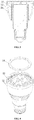
- FIGS. 1-4 illustrate an exemplary LED lighting device consistent with various disclosed embodiments of present disclosure.
- the LED lighting device may include an LED driving circuit and power supply unit 10, an LED light source component unit 11, a heat sink 12, an RF circuit (not shown), and an RF antenna 14.
- the LED driving circuit and power supply unit 10 can drive the LED light source component unit 11, and provide power to the entire LED lighting device 1.
- the RF circuit can be configured in the LED lighting device 1 and can be electrically connected to the RF antenna 14.
- the RF antenna 14 can be configured to transmit and receive RF signals.
- the LED light source component unit 11 may include a circular LED board 24, which may be configured with at least one LED light source 25.
- the RF antenna 14 shown in FIGS. 1-4 may be a PCB antenna made of PCB materials having various different dielectric constants, or an onboard ceramic antenna made of ceramic materials having various different dielectric constants, or any other suitable antennas.
- the heat sink 12 may include a heat sink body 21 and a plurality of heat sink fins 22 longitudinally configured and distributed on an upper portion along the outer periphery of the heat sink body 21.
- the heat sink fins 22 may be housed by a cooling case 23.
- the LED board 24 may be fixed on a top surface of the heat sink body 21.
- the RF antenna 14 may have an annular shape with a central aperture to allow light beam emitted from the LED light source component unit 11 to pass through the central aperture of the RF antenna 14 without affecting the light-emitting path from the LED light source component unit 11.
- the inner diameter of the RF antenna 14 may equal to the outer diameter of the LED board 24.
- the RF antenna 14 may be socket-configured along the outer periphery of the LED board 24.
- the upper portion of the cooling case 23 may be higher than the top surfaces of the heat sink fins 22 and the RF antenna 14.
- the outer periphery of the RF antenna 14 and the inner sidewall of the cooling case 23 may be separated by a gap.
- the RF antenna 14 and the cooling case 23 may be connected with snap connectors.
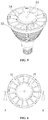
- FIGS. 5-8 illustrate another exemplary LED lighting device consistent with various disclosed embodiments.
- the RF antenna 14 shown in FIGS. 5-8 may be a metal film antenna made of unique metal materials capable of improving the dielectric constant.
- the LED light source component unit 11 may further include a lens 15 fixed on the circular LED board 24.
- the lens 15 may be transparent to visible light and may cover the LED light source.
- the RF antenna 14 may be an annular metal film antenna mounted around the outer periphery of the lower portion of the lens 15, such that the configured RF antenna 14 does not affect light-emitting path from the light source component unit 11.
- the antenna top plane containing the highest point of the RF antenna 14 is lower than a plane (e.g., a horizontal plane) containing the highest point of the cooling case 23.
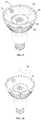
- FIGS. 9-11 illustrate another exemplary LED lighting device.
- the RF antenna 14 shown in FIGS. 9-11 may be a FPC antenna made of flexible materials with various different dielectric constants, or an LDS antenna made by laser direct structuring technology (not claimed).
- the LED light source component unit 11 may further include a reflecting shade (or cover) 16 fixed on the LED board.
- the upper portion of each of the cooling case 23 and the heat sink fins 22 may be higher than a top surface of the LED board 24.
- a cavity 31 can be defined by the upper portion of the heat sink fins 22, the upper portion of the cooling sink 23, and the LED board 24 as shown in FIG. 9 .
- the reflecting shade 16 may be located in the cavity 31.
- the RF antenna 14 may be mounted on the reflecting shade 16 without affecting the light-emitting path from the LED light source component unit 11.
- the antenna top plane containing a highest point of the RF antenna 14 may be coplanar with or lower than a heat sink top plane containing a highest point of the heat sink.
- the disclosed RF antenna 14 (e.g., shown in FIGS. 1-11 ) can be configured such that an antenna top plane that contains the highest point of the RF antenna 14 is lower than a heat-sink top plane that contains the highest point of the heat sink 12, without affecting a light-emitting path from the LED light source component unit 11.
- the antenna top plane of the RF antenna 14 can be configured in parallel with the heat-sink top plane of the heat sink 12.
- the antenna top plane of the RF antenna 14 can be configured coplanar (in a same plane) with the heat-sink top plane of the heat sink 12.
- the present disclosure is primarily described with respect to an exemplary LED lighting device configured or placed in a position to emit light upwardly.
- the disclosed LED lighting device may further include a shell.
- the shell may be a part of the heat sink 12.
- FIG. 12 shows an exemplary LED lighting system consistent with various disclosed embodiments of the present disclosure.
- the LED lighting system may include the LED lighting device 1 configured with the RF antenna 14 and a terminal 2.
- Terminal 2 is configured to provide wireless control and communication with the LED lighting device 1 through the RF antenna 14.
- Antenna-containing LED lighting devices, systems and configuring methods are provided.
- An exemplary LED lighting device includes an LED light source component unit and an LED driving circuit and power supply unit configured to drive the LED light source component unit and to power the LED lighting device.
- the LED lighting device further includes a heat sink, an RF antenna, and an RF circuit.
- the RF antenna is configured to have an antenna top plane containing a highest point of the RF antenna coplanar with or lower than a heat sink top plane containing a highest point of the heat sink.
- the RF antenna is configured without affecting a light-emitting path from the LED light source component unit.
- the RF antenna may be configured into various shapes so that the antenna would conform to shape of the LED lighting device without obstructing the lighting path of the device.
- the disclosed antenna-containing LED lighting devices, systems and configuring methods may thus have desired RF properties for wireless communication and wireless control.
- the disclosed RF antenna is configured to have the antenna top plane containing the highest point of the RF antenna coplanar with or lower than the heat sink top plane containing the highest point of the heat sink. Therefore, the quality and stability of the RF signals are improved without affecting the light-emitting path of the LED lighting device.
Landscapes
- Engineering & Computer Science (AREA)
- General Engineering & Computer Science (AREA)
- Physics & Mathematics (AREA)
- Microelectronics & Electronic Packaging (AREA)
- Optics & Photonics (AREA)
- Computer Networks & Wireless Communication (AREA)
- Arrangement Of Elements, Cooling, Sealing, Or The Like Of Lighting Devices (AREA)
- Non-Portable Lighting Devices Or Systems Thereof (AREA)
Claims (6)
- LED-Beleuchtungsvorrichtung, umfassend:- eine LED-Lichtquellenkomponenteneinheit (11) beinhaltend eine LED-Platine (24) und zumindest eine LED-Lichtquelle (25), die auf der LED-Platine (24) konfiguriert ist;- eine LED-Treiberschaltung und -Energieversorgungseinheit (10), die konfiguriert ist, um die LED-Lichtquellenkomponenteneinheit (11) zu betreiben und die LED-Beleuchtungsvorrichtung mit Energie zu versorgen;- eine Wärmesenke (12) beinhaltend einen Kühlkörper (21), eine Vielzahl von Wärmesenkerippen (22), die in Längsrichtung ausgebildet und über einen oberen Abschnitt entlang einer Außenumfangsfläche des Kühlkörpers (21) verteilt sind, und ein Kühlgehäuse (23), in dem die Vielzahl von Wärmesenkerippen (22) untergebracht sind;- eine HF-Antenne (14) aufweisend eine ringförmige Form mit einer zentralen Öffnung, damit ein Lichtstrahl, der von der LED-Lichtquellenkomponenteneinheit (11) ausgestrahlt wird, durch die zentrale Öffnung hindurchtreten kann; und- eine HF-Schaltung (13),wobei:- die HF-Antenne (14) so konfiguriert ist, dass sie eine obere Antennenebene aufweist, die einen höchsten Punkt der HF-Antenne (14) enthält, die koplanar ist mit oder niedriger ist als eine/r oberen Wärmesenkenebene, die einen höchsten Punkt der Wärmesenke (12) enthält, und- die HF-Antenne (14) so konfiguriert ist, dass sie einen Lichtemissionspfad der LED-Lichtquellenkomponenteneinheit (11) nicht beeinflusst,- die LED-Platine (24) eine kreisförmige Form hat und auf einer oberen Oberfläche des Kühlkörpers (21) befestigt ist,- die HF-Antenne (14) als Buchse auf einer Außenumfangsfläche der LED-Platine (24) konfiguriert ist, und- ein oberer Abschnitt des Kühlgehäuses (23) höher ist als eine obere Oberfläche von jeder der Vielzahl von Wärmesenkerippen (22) und der HF-Antenne (14)dadurch gekennzeichnet, dass- die HF-Antenne (14) eine Leiterplatinen(PCB)-Antenne oder eine Onboard-Keramikantenne ist, und eine ringförmige Form hat;- das Kühlgehäuse (23) einen kreisförmigen Querschnitt hat;- eine Außenumfangsfläche der HF-Antenne (14) und eine innere Seitenwand des Kühlgehäuses (23) durch einen Spalt voneinander getrennt sind; und- die HF-Antenne (14) und das Kühlgehäuse (23) mit Schnappverbindern verbunden sind.
- LED-Beleuchtungsvorrichtung nach Anspruch 1, wobei die HF-Antenne (14) eine invertierte F-Antenne (IFA), eine planare invertierte F-Antenne (PIFA), eine Monopolantenne oder eine Schleifenantenne ist.
- LED-Beleuchtungsvorrichtung nach Anspruch 1, wobei die LED-Beleuchtungsvorrichtung ferner eine Schale als Teil der Wärmesenke (12) aufweist.
- LED-Beleuchtungssystem, aufweisend eine beliebige der LED-Beleuchtungsvorrichtungen nach den Ansprüchen 1 - 5, und ein Endgerät, das zur drahtlosen Steuerung und Kommunikation mit der LED-Beleuchtungsvorrichtung konfiguriert ist.
- Verfahren zum Konfigurieren der HF-Antenne (14) in einer LED-Beleuchtungsvorrichtung mit:- einer Wärmesenke (12), wobei die Wärmesenke (12) einen Kühlkörper (21) beinhaltet, einer Vielzahl von Wärmesenkerippen (22), die in Längsrichtung ausgebildet und über einen oberen Abschnitt entlang einer Außenumfangsfläche des Kühlkörpers (21) verteilt sind, und ein Kühlgehäuse (23), in dem die Vielzahl von Wärmesenkerippen (22) untergebracht sind;- eine LED-Lichtquellenkomponenteneinheit (11) beinhaltend ein kreisförmige LED-Platine (24), die auf einer oberen Oberfläche des Kühlkörpers (21) der Wärmesenke (12) befestigt ist und zumindest eine auf der LED-Platine (24) ausgebildete LED-Lichtquelle (25), eine LED-Treiberschaltung und -Energieversorgungseinheit (10), die konfiguriert ist, um die LED-Lichtquellenkomponenteneinheit (11) zu betreiben und die LED-Beleuchtungsvorrichtung mit Energie zu versorgen,- eine HF-Antenne (14) und eine HF-Schaltung (13),wobei das Verfahren Folgendes aufweist:- Konfigurieren der HF-Antenne (14), so dass sie eine obere Antennenebene hat, die einen höchsten Punkt der HF-Antenne (14) enthält, die koplanar ist mit oder niedriger ist als eine obere Wärmesenkenebene, die einen höchsten Punkt der Wärmesenke (12) enthält, wobei ein Lichtemissionspfad der LED-Beleuchtungsvorrichtung nicht durch die konfigurierte HF-Antenne (14) beeinflusst wird,- Konfigurieren der HF-Antenne (14), so dass sie eine ringförmige Form hat mit einer zentralen Öffnung, um zu ermöglichen, dass ein von der LED-Lichtquellenkomponenteneinheit (11) emittierter Lichtstrahl durch die zentrale Öffnung hindurchtritt, ohne dass der Lichtemissionspfad der LED-Lichtquellenkomponenteneinheit (11) beeinflusst wird,- Konfigurieren der HF-Antenne (14) als Buchse auf einer Außenumfangsfläche der LED-Platine (24), und- Konfigurieren eines oberen Abschnittes des Kühlgehäuses (23), so dass er höher ist als eine obere Oberfläche von jeder der Vielzahl von Wärmesenkerippen (22) und der HF-Antenne (14),wobei das Verfahren weiterhin aufweist:- Konfigurieren der HF-Antenne (14) als eine Leiterplatinen(PCB)-Antenne oder eine Onboard-Keramikantenne, und mit einer ringförmigen Form;- Konfigurieren des Kühlgehäuses (23), so dass es einen kreisförmigen Querschnitt hat;- Trennen einer Außenumfangsfläche der HF-Antenne (14) und einer inneren Seitenwand des Kühlgehäuses (23) durch einen Spalt; und- Verbinden der HF-Antenne (14) und des Kühlgehäuses (23) mit Schnappverbindern.
- Verfahren zum Konfigurieren der HF-Antenne nach Anspruch 1,
dadurch gekennzeichnet, dass
die HF-Antenne (14) invertierte F-Antenne (IFA), eine planare invertierte F-Antenne (PIFA), eine Monopolantenne oder eine Schleifenantenne ist.
Applications Claiming Priority (2)
| Application Number | Priority Date | Filing Date | Title |
|---|---|---|---|
| CN201410133329.5A CN103912810A (zh) | 2014-04-03 | 2014-04-03 | Led照明装置、系统以及在led照明装置内布置天线的方法 |
| PCT/CN2015/073870 WO2015149605A1 (en) | 2014-04-03 | 2015-03-09 | Led lighting device and system containing antenna, and related configuring method |
Publications (3)
| Publication Number | Publication Date |
|---|---|
| EP3132183A1 EP3132183A1 (de) | 2017-02-22 |
| EP3132183A4 EP3132183A4 (de) | 2017-08-30 |
| EP3132183B1 true EP3132183B1 (de) | 2019-05-15 |
Family
ID=51038696
Family Applications (1)
| Application Number | Title | Priority Date | Filing Date |
|---|---|---|---|
| EP15773371.8A Active EP3132183B1 (de) | 2014-04-03 | 2015-03-09 | Led-beleuchtungsvorrichtung und -system mit antenne und zugehöriges konfigurierungsverfahren |
Country Status (4)
| Country | Link |
|---|---|
| US (1) | US9635742B2 (de) |
| EP (1) | EP3132183B1 (de) |
| CN (1) | CN103912810A (de) |
| WO (1) | WO2015149605A1 (de) |
Cited By (1)
| Publication number | Priority date | Publication date | Assignee | Title |
|---|---|---|---|---|
| EP3996203B1 (de) * | 2020-11-06 | 2024-08-28 | Rockwell Collins, Inc. | Antennenanordnung für luftfahrzeuge und beleuchtungssystemintegrationen |
Families Citing this family (20)
| Publication number | Priority date | Publication date | Assignee | Title |
|---|---|---|---|---|
| CN103912810A (zh) | 2014-04-03 | 2014-07-09 | 生迪光电科技股份有限公司 | Led照明装置、系统以及在led照明装置内布置天线的方法 |
| CN104154440A (zh) * | 2014-07-29 | 2014-11-19 | 浙江生辉照明有限公司 | 智能led照明装置及智能led照明系统 |
| CN104566029A (zh) * | 2014-12-26 | 2015-04-29 | 生迪光电科技股份有限公司 | Led照明装置、系统及复位键布置方法 |
| CN104566027B (zh) | 2014-12-26 | 2018-10-26 | 生迪光电科技股份有限公司 | Led照明装置、系统及其天线布置方法 |
| JP2017529006A (ja) | 2015-07-31 | 2017-09-28 | 日本電気株式会社 | 送信を実行する方法および装置 |
| ES2832755T3 (es) * | 2017-03-01 | 2021-06-11 | Signify Holding Bv | Dispositivo de iluminación con antena de ranura |
| CN206943945U (zh) * | 2017-06-23 | 2018-01-30 | 深圳佳比泰智能照明股份有限公司 | 一种射灯 |
| CN207691004U (zh) * | 2017-10-31 | 2018-08-03 | 生迪智慧科技有限公司 | 旋转天线 |
| JP7016056B2 (ja) * | 2018-02-22 | 2022-02-04 | パナソニックIpマネジメント株式会社 | 照明器具 |
| CN108533975A (zh) * | 2018-05-15 | 2018-09-14 | 黄世明 | 一种外置蓝牙天线的灯具 |
| WO2019228859A1 (en) * | 2018-05-31 | 2019-12-05 | Signify Holding B.V. | Stacked circuit boards within a lighting device |
| ES2884941T3 (es) * | 2018-09-20 | 2021-12-13 | Signify Holding Bv | Dispositivo de iluminación |
| CN209130543U (zh) * | 2018-11-13 | 2019-07-19 | 漳州立达信光电子科技有限公司 | 一种智能灯 |
| AU2020226734A1 (en) * | 2019-02-21 | 2021-09-30 | Dialight Corporation | Led lighting assembly with integrated power conversion and digital transceiver |
| CN211625172U (zh) * | 2020-01-16 | 2020-10-02 | 漳州立达信光电子科技有限公司 | 一种光源智能组件及具有其的射频控制照明灯具 |
| CN212960971U (zh) * | 2020-08-05 | 2021-04-13 | 漳州立达信光电子科技有限公司 | 智能灯 |
| US11325690B1 (en) | 2020-10-19 | 2022-05-10 | Rockwell Collins, Inc. | Integrated aircraft antenna and light assemblies |
| US20240189471A1 (en) * | 2021-04-20 | 2024-06-13 | Shanghai Sansi Electronic Engineering Co. Ltd. | Multi-band led disinfection system and multi-band led disinfection lamp |
| CN114173234A (zh) * | 2021-12-08 | 2022-03-11 | 江西台德智慧科技有限公司 | 无线传输性能优异的智能终端 |
| WO2025184577A1 (en) * | 2024-02-28 | 2025-09-04 | Lutron Technology Company Llc | Single-layer printed circuit board for a lighting device |
Family Cites Families (17)
| Publication number | Priority date | Publication date | Assignee | Title |
|---|---|---|---|---|
| CN101809366B (zh) * | 2007-09-27 | 2013-01-02 | 皇家飞利浦电子股份有限公司 | 发光设备以及冷却发光设备的方法 |
| EP2438647B1 (de) * | 2009-06-05 | 2013-10-16 | Koninklijke Philips N.V. | Beleuchtungseinrichtung mit eingebauter hf-antenne |
| JP5297301B2 (ja) * | 2009-08-24 | 2013-09-25 | パナソニック株式会社 | 照明装置 |
| CN202075798U (zh) * | 2011-01-05 | 2011-12-14 | 陈亮 | 手持式照明巡检设备 |
| US20130063317A1 (en) * | 2011-03-10 | 2013-03-14 | Greenwave Reality, Pte Ltd. | Antenna Integrated into Optical Element |
| JP5793662B2 (ja) * | 2011-04-20 | 2015-10-14 | パナソニックIpマネジメント株式会社 | 照明用光源 |
| US20140168020A1 (en) * | 2011-05-03 | 2014-06-19 | Galtronics Corporation Ltd. | Antenna combined with lighting device |
| US9217555B2 (en) * | 2011-05-17 | 2015-12-22 | Bridgelux Incorporated | LED module with integrated thermal spreader |
| KR20130057372A (ko) * | 2011-11-23 | 2013-05-31 | 삼성전기주식회사 | 안테나를 구비한 전등 및 그 제조 방법 |
| CN102425734B (zh) * | 2011-11-25 | 2014-07-23 | 生迪光电科技股份有限公司 | 一种led灯 |
| TWI446830B (zh) * | 2011-11-30 | 2014-07-21 | Amtran Technology Co Ltd | 發光二極體燈源 |
| KR101896958B1 (ko) * | 2011-12-19 | 2018-10-18 | 엘지이노텍 주식회사 | Led 조명장치 |
| CN104136834A (zh) * | 2012-01-06 | 2014-11-05 | 瑟莫尔解决方案资源有限责任公司 | 具有增强无线通讯的led灯 |
| US8633646B2 (en) * | 2012-04-30 | 2014-01-21 | Freescale Semiconductor, Inc. | Method and apparatus for radio-frequency controllable LED lamp fixture antenna |
| CN102798018B (zh) * | 2012-08-17 | 2015-10-21 | 厦门立达信照明有限公司 | 遥控led灯 |
| CN103912810A (zh) * | 2014-04-03 | 2014-07-09 | 生迪光电科技股份有限公司 | Led照明装置、系统以及在led照明装置内布置天线的方法 |
| CN203810121U (zh) * | 2014-04-03 | 2014-09-03 | 生迪光电科技股份有限公司 | Led照明装置及led照明系统 |
-
2014
- 2014-04-03 CN CN201410133329.5A patent/CN103912810A/zh active Pending
-
2015
- 2015-03-09 US US15/022,590 patent/US9635742B2/en active Active
- 2015-03-09 EP EP15773371.8A patent/EP3132183B1/de active Active
- 2015-03-09 WO PCT/CN2015/073870 patent/WO2015149605A1/en not_active Ceased
Non-Patent Citations (1)
| Title |
|---|
| None * |
Cited By (1)
| Publication number | Priority date | Publication date | Assignee | Title |
|---|---|---|---|---|
| EP3996203B1 (de) * | 2020-11-06 | 2024-08-28 | Rockwell Collins, Inc. | Antennenanordnung für luftfahrzeuge und beleuchtungssystemintegrationen |
Also Published As
| Publication number | Publication date |
|---|---|
| EP3132183A1 (de) | 2017-02-22 |
| WO2015149605A1 (en) | 2015-10-08 |
| US9635742B2 (en) | 2017-04-25 |
| EP3132183A4 (de) | 2017-08-30 |
| US20160227636A1 (en) | 2016-08-04 |
| CN103912810A (zh) | 2014-07-09 |
Similar Documents
| Publication | Publication Date | Title |
|---|---|---|
| EP3132183B1 (de) | Led-beleuchtungsvorrichtung und -system mit antenne und zugehöriges konfigurierungsverfahren | |
| RU2653572C1 (ru) | Осветительное устройство с первой и второй связанными и взаимоподвижными антеннами | |
| JP6406603B2 (ja) | 照明器具 | |
| US10779384B2 (en) | Lighting system | |
| US8633646B2 (en) | Method and apparatus for radio-frequency controllable LED lamp fixture antenna | |
| US20140168020A1 (en) | Antenna combined with lighting device | |
| KR101999660B1 (ko) | 통신 모듈을 포함하는 조명 장치 | |
| US9960475B2 (en) | LED lighting device and system, and antenna arrangement method | |
| CN105122544B (zh) | 包括天线的照明装置以及灯具 | |
| JP6151274B2 (ja) | 機能強化された無線通信を有するledランプ | |
| EP3033568B1 (de) | Eine beleuchtungseinrichtung und leuchte mit antenne | |
| US9404624B2 (en) | Lighting apparatus | |
| EP2745350B2 (de) | Beleuchtungsvorrichtung mit einer rf-antenne | |
| EP3590149B1 (de) | Beleuchtungsvorrichtung mit schlitzantenne | |
| EP3255339B1 (de) | Festkörperbeleuchtungsvorrichtung mit einer drahtloskommunikationsantenne | |
| US20150195892A1 (en) | Lighting device | |
| KR20150129388A (ko) | 조명 장치 | |
| EP2925091B1 (de) | Scheinwerfer-LED-Modul und Lichtmodul | |
| KR20170027287A (ko) | 전구형 벌브 | |
| TW201346180A (zh) | 與照明裝置結合之天線 | |
| KR20150111218A (ko) | 조명기기 |
Legal Events
| Date | Code | Title | Description |
|---|---|---|---|
| STAA | Information on the status of an ep patent application or granted ep patent |
Free format text: STATUS: THE INTERNATIONAL PUBLICATION HAS BEEN MADE |
|
| PUAI | Public reference made under article 153(3) epc to a published international application that has entered the european phase |
Free format text: ORIGINAL CODE: 0009012 |
|
| STAA | Information on the status of an ep patent application or granted ep patent |
Free format text: STATUS: REQUEST FOR EXAMINATION WAS MADE |
|
| 17P | Request for examination filed |
Effective date: 20161103 |
|
| AK | Designated contracting states |
Kind code of ref document: A1 Designated state(s): AL AT BE BG CH CY CZ DE DK EE ES FI FR GB GR HR HU IE IS IT LI LT LU LV MC MK MT NL NO PL PT RO RS SE SI SK SM TR |
|
| AX | Request for extension of the european patent |
Extension state: BA ME |
|
| DAV | Request for validation of the european patent (deleted) | ||
| DAX | Request for extension of the european patent (deleted) | ||
| A4 | Supplementary search report drawn up and despatched |
Effective date: 20170727 |
|
| RIC1 | Information provided on ipc code assigned before grant |
Ipc: F21V 23/04 20060101AFI20170721BHEP Ipc: F21V 29/77 20150101ALI20170721BHEP Ipc: F21Y 115/10 20160101ALN20170721BHEP Ipc: F21K 9/233 20160101ALI20170721BHEP Ipc: F21V 17/16 20060101ALI20170721BHEP |
|
| STAA | Information on the status of an ep patent application or granted ep patent |
Free format text: STATUS: EXAMINATION IS IN PROGRESS |
|
| 17Q | First examination report despatched |
Effective date: 20180605 |
|
| GRAP | Despatch of communication of intention to grant a patent |
Free format text: ORIGINAL CODE: EPIDOSNIGR1 |
|
| STAA | Information on the status of an ep patent application or granted ep patent |
Free format text: STATUS: GRANT OF PATENT IS INTENDED |
|
| RIC1 | Information provided on ipc code assigned before grant |
Ipc: F21V 23/04 20060101AFI20181023BHEP Ipc: F21Y 115/10 20160101ALN20181023BHEP Ipc: F21V 29/77 20150101ALI20181023BHEP Ipc: F21V 17/16 20060101ALI20181023BHEP Ipc: F21K 9/233 20160101ALI20181023BHEP |
|
| INTG | Intention to grant announced |
Effective date: 20181205 |
|
| GRAJ | Information related to disapproval of communication of intention to grant by the applicant or resumption of examination proceedings by the epo deleted |
Free format text: ORIGINAL CODE: EPIDOSDIGR1 |
|
| REG | Reference to a national code |
Ref country code: DE Ref legal event code: R079 Ref document number: 602015030410 Country of ref document: DE Free format text: PREVIOUS MAIN CLASS: F21S0002000000 Ipc: F21V0023040000 |
|
| STAA | Information on the status of an ep patent application or granted ep patent |
Free format text: STATUS: EXAMINATION IS IN PROGRESS |
|
| GRAR | Information related to intention to grant a patent recorded |
Free format text: ORIGINAL CODE: EPIDOSNIGR71 |
|
| GRAS | Grant fee paid |
Free format text: ORIGINAL CODE: EPIDOSNIGR3 |
|
| STAA | Information on the status of an ep patent application or granted ep patent |
Free format text: STATUS: GRANT OF PATENT IS INTENDED |
|
| GRAA | (expected) grant |
Free format text: ORIGINAL CODE: 0009210 |
|
| STAA | Information on the status of an ep patent application or granted ep patent |
Free format text: STATUS: THE PATENT HAS BEEN GRANTED |
|
| INTC | Intention to grant announced (deleted) | ||
| RIC1 | Information provided on ipc code assigned before grant |
Ipc: F21K 9/233 20160101ALI20190403BHEP Ipc: F21V 29/77 20150101ALI20190403BHEP Ipc: F21V 17/16 20060101ALI20190403BHEP Ipc: F21V 23/04 20060101AFI20190403BHEP Ipc: F21Y 115/10 20160101ALN20190403BHEP |
|
| AK | Designated contracting states |
Kind code of ref document: B1 Designated state(s): AL AT BE BG CH CY CZ DE DK EE ES FI FR GB GR HR HU IE IS IT LI LT LU LV MC MK MT NL NO PL PT RO RS SE SI SK SM TR |
|
| INTG | Intention to grant announced |
Effective date: 20190405 |
|
| REG | Reference to a national code |
Ref country code: CH Ref legal event code: EP |
|
| REG | Reference to a national code |
Ref country code: DE Ref legal event code: R096 Ref document number: 602015030410 Country of ref document: DE |
|
| REG | Reference to a national code |
Ref country code: IE Ref legal event code: FG4D |
|
| REG | Reference to a national code |
Ref country code: NL Ref legal event code: MP Effective date: 20190515 |
|
| REG | Reference to a national code |
Ref country code: LT Ref legal event code: MG4D |
|
| PG25 | Lapsed in a contracting state [announced via postgrant information from national office to epo] |
Ref country code: NO Free format text: LAPSE BECAUSE OF FAILURE TO SUBMIT A TRANSLATION OF THE DESCRIPTION OR TO PAY THE FEE WITHIN THE PRESCRIBED TIME-LIMIT Effective date: 20190815 Ref country code: FI Free format text: LAPSE BECAUSE OF FAILURE TO SUBMIT A TRANSLATION OF THE DESCRIPTION OR TO PAY THE FEE WITHIN THE PRESCRIBED TIME-LIMIT Effective date: 20190515 Ref country code: LT Free format text: LAPSE BECAUSE OF FAILURE TO SUBMIT A TRANSLATION OF THE DESCRIPTION OR TO PAY THE FEE WITHIN THE PRESCRIBED TIME-LIMIT Effective date: 20190515 Ref country code: NL Free format text: LAPSE BECAUSE OF FAILURE TO SUBMIT A TRANSLATION OF THE DESCRIPTION OR TO PAY THE FEE WITHIN THE PRESCRIBED TIME-LIMIT Effective date: 20190515 Ref country code: AL Free format text: LAPSE BECAUSE OF FAILURE TO SUBMIT A TRANSLATION OF THE DESCRIPTION OR TO PAY THE FEE WITHIN THE PRESCRIBED TIME-LIMIT Effective date: 20190515 Ref country code: PT Free format text: LAPSE BECAUSE OF FAILURE TO SUBMIT A TRANSLATION OF THE DESCRIPTION OR TO PAY THE FEE WITHIN THE PRESCRIBED TIME-LIMIT Effective date: 20190915 Ref country code: ES Free format text: LAPSE BECAUSE OF FAILURE TO SUBMIT A TRANSLATION OF THE DESCRIPTION OR TO PAY THE FEE WITHIN THE PRESCRIBED TIME-LIMIT Effective date: 20190515 Ref country code: SE Free format text: LAPSE BECAUSE OF FAILURE TO SUBMIT A TRANSLATION OF THE DESCRIPTION OR TO PAY THE FEE WITHIN THE PRESCRIBED TIME-LIMIT Effective date: 20190515 Ref country code: HR Free format text: LAPSE BECAUSE OF FAILURE TO SUBMIT A TRANSLATION OF THE DESCRIPTION OR TO PAY THE FEE WITHIN THE PRESCRIBED TIME-LIMIT Effective date: 20190515 |
|
| PG25 | Lapsed in a contracting state [announced via postgrant information from national office to epo] |
Ref country code: RS Free format text: LAPSE BECAUSE OF FAILURE TO SUBMIT A TRANSLATION OF THE DESCRIPTION OR TO PAY THE FEE WITHIN THE PRESCRIBED TIME-LIMIT Effective date: 20190515 Ref country code: LV Free format text: LAPSE BECAUSE OF FAILURE TO SUBMIT A TRANSLATION OF THE DESCRIPTION OR TO PAY THE FEE WITHIN THE PRESCRIBED TIME-LIMIT Effective date: 20190515 Ref country code: GR Free format text: LAPSE BECAUSE OF FAILURE TO SUBMIT A TRANSLATION OF THE DESCRIPTION OR TO PAY THE FEE WITHIN THE PRESCRIBED TIME-LIMIT Effective date: 20190816 Ref country code: BG Free format text: LAPSE BECAUSE OF FAILURE TO SUBMIT A TRANSLATION OF THE DESCRIPTION OR TO PAY THE FEE WITHIN THE PRESCRIBED TIME-LIMIT Effective date: 20190815 |
|
| REG | Reference to a national code |
Ref country code: AT Ref legal event code: MK05 Ref document number: 1133866 Country of ref document: AT Kind code of ref document: T Effective date: 20190515 |
|
| PG25 | Lapsed in a contracting state [announced via postgrant information from national office to epo] |
Ref country code: CZ Free format text: LAPSE BECAUSE OF FAILURE TO SUBMIT A TRANSLATION OF THE DESCRIPTION OR TO PAY THE FEE WITHIN THE PRESCRIBED TIME-LIMIT Effective date: 20190515 Ref country code: EE Free format text: LAPSE BECAUSE OF FAILURE TO SUBMIT A TRANSLATION OF THE DESCRIPTION OR TO PAY THE FEE WITHIN THE PRESCRIBED TIME-LIMIT Effective date: 20190515 Ref country code: AT Free format text: LAPSE BECAUSE OF FAILURE TO SUBMIT A TRANSLATION OF THE DESCRIPTION OR TO PAY THE FEE WITHIN THE PRESCRIBED TIME-LIMIT Effective date: 20190515 Ref country code: DK Free format text: LAPSE BECAUSE OF FAILURE TO SUBMIT A TRANSLATION OF THE DESCRIPTION OR TO PAY THE FEE WITHIN THE PRESCRIBED TIME-LIMIT Effective date: 20190515 Ref country code: SK Free format text: LAPSE BECAUSE OF FAILURE TO SUBMIT A TRANSLATION OF THE DESCRIPTION OR TO PAY THE FEE WITHIN THE PRESCRIBED TIME-LIMIT Effective date: 20190515 |
|
| REG | Reference to a national code |
Ref country code: DE Ref legal event code: R097 Ref document number: 602015030410 Country of ref document: DE |
|
| PG25 | Lapsed in a contracting state [announced via postgrant information from national office to epo] |
Ref country code: IT Free format text: LAPSE BECAUSE OF FAILURE TO SUBMIT A TRANSLATION OF THE DESCRIPTION OR TO PAY THE FEE WITHIN THE PRESCRIBED TIME-LIMIT Effective date: 20190515 Ref country code: SM Free format text: LAPSE BECAUSE OF FAILURE TO SUBMIT A TRANSLATION OF THE DESCRIPTION OR TO PAY THE FEE WITHIN THE PRESCRIBED TIME-LIMIT Effective date: 20190515 |
|
| PLBE | No opposition filed within time limit |
Free format text: ORIGINAL CODE: 0009261 |
|
| STAA | Information on the status of an ep patent application or granted ep patent |
Free format text: STATUS: NO OPPOSITION FILED WITHIN TIME LIMIT |
|
| PG25 | Lapsed in a contracting state [announced via postgrant information from national office to epo] |
Ref country code: TR Free format text: LAPSE BECAUSE OF FAILURE TO SUBMIT A TRANSLATION OF THE DESCRIPTION OR TO PAY THE FEE WITHIN THE PRESCRIBED TIME-LIMIT Effective date: 20190515 |
|
| 26N | No opposition filed |
Effective date: 20200218 |
|
| PG25 | Lapsed in a contracting state [announced via postgrant information from national office to epo] |
Ref country code: PL Free format text: LAPSE BECAUSE OF FAILURE TO SUBMIT A TRANSLATION OF THE DESCRIPTION OR TO PAY THE FEE WITHIN THE PRESCRIBED TIME-LIMIT Effective date: 20190515 |
|
| PG25 | Lapsed in a contracting state [announced via postgrant information from national office to epo] |
Ref country code: SI Free format text: LAPSE BECAUSE OF FAILURE TO SUBMIT A TRANSLATION OF THE DESCRIPTION OR TO PAY THE FEE WITHIN THE PRESCRIBED TIME-LIMIT Effective date: 20190515 |
|
| PG25 | Lapsed in a contracting state [announced via postgrant information from national office to epo] |
Ref country code: MC Free format text: LAPSE BECAUSE OF FAILURE TO SUBMIT A TRANSLATION OF THE DESCRIPTION OR TO PAY THE FEE WITHIN THE PRESCRIBED TIME-LIMIT Effective date: 20190515 |
|
| REG | Reference to a national code |
Ref country code: CH Ref legal event code: PL |
|
| REG | Reference to a national code |
Ref country code: BE Ref legal event code: MM Effective date: 20200331 |
|
| PG25 | Lapsed in a contracting state [announced via postgrant information from national office to epo] |
Ref country code: LU Free format text: LAPSE BECAUSE OF NON-PAYMENT OF DUE FEES Effective date: 20200309 |
|
| PG25 | Lapsed in a contracting state [announced via postgrant information from national office to epo] |
Ref country code: LI Free format text: LAPSE BECAUSE OF NON-PAYMENT OF DUE FEES Effective date: 20200331 Ref country code: CH Free format text: LAPSE BECAUSE OF NON-PAYMENT OF DUE FEES Effective date: 20200331 Ref country code: IE Free format text: LAPSE BECAUSE OF NON-PAYMENT OF DUE FEES Effective date: 20200309 |
|
| PG25 | Lapsed in a contracting state [announced via postgrant information from national office to epo] |
Ref country code: BE Free format text: LAPSE BECAUSE OF NON-PAYMENT OF DUE FEES Effective date: 20200331 |
|
| PG25 | Lapsed in a contracting state [announced via postgrant information from national office to epo] |
Ref country code: MT Free format text: LAPSE BECAUSE OF FAILURE TO SUBMIT A TRANSLATION OF THE DESCRIPTION OR TO PAY THE FEE WITHIN THE PRESCRIBED TIME-LIMIT Effective date: 20190515 Ref country code: CY Free format text: LAPSE BECAUSE OF FAILURE TO SUBMIT A TRANSLATION OF THE DESCRIPTION OR TO PAY THE FEE WITHIN THE PRESCRIBED TIME-LIMIT Effective date: 20190515 |
|
| PG25 | Lapsed in a contracting state [announced via postgrant information from national office to epo] |
Ref country code: RO Free format text: LAPSE BECAUSE OF FAILURE TO SUBMIT A TRANSLATION OF THE DESCRIPTION OR TO PAY THE FEE WITHIN THE PRESCRIBED TIME-LIMIT Effective date: 20190515 Ref country code: MK Free format text: LAPSE BECAUSE OF FAILURE TO SUBMIT A TRANSLATION OF THE DESCRIPTION OR TO PAY THE FEE WITHIN THE PRESCRIBED TIME-LIMIT Effective date: 20190515 Ref country code: IS Free format text: LAPSE BECAUSE OF FAILURE TO SUBMIT A TRANSLATION OF THE DESCRIPTION OR TO PAY THE FEE WITHIN THE PRESCRIBED TIME-LIMIT Effective date: 20190915 |
|
| PGFP | Annual fee paid to national office [announced via postgrant information from national office to epo] |
Ref country code: DE Payment date: 20250328 Year of fee payment: 11 |
|
| PGFP | Annual fee paid to national office [announced via postgrant information from national office to epo] |
Ref country code: FR Payment date: 20250327 Year of fee payment: 11 |
|
| PGFP | Annual fee paid to national office [announced via postgrant information from national office to epo] |
Ref country code: GB Payment date: 20250423 Year of fee payment: 11 |