EP3132319B1 - Procédé d'exploitation d'un système d'automatisation - Google Patents
Procédé d'exploitation d'un système d'automatisation Download PDFInfo
- Publication number
- EP3132319B1 EP3132319B1 EP15717855.9A EP15717855A EP3132319B1 EP 3132319 B1 EP3132319 B1 EP 3132319B1 EP 15717855 A EP15717855 A EP 15717855A EP 3132319 B1 EP3132319 B1 EP 3132319B1
- Authority
- EP
- European Patent Office
- Prior art keywords
- computer program
- manipulator
- plc
- cell control
- input
- Prior art date
- Legal status (The legal status is an assumption and is not a legal conclusion. Google has not performed a legal analysis and makes no representation as to the accuracy of the status listed.)
- Active
Links
Images


Classifications
-
- G—PHYSICS
- G05—CONTROLLING; REGULATING
- G05B—CONTROL OR REGULATING SYSTEMS IN GENERAL; FUNCTIONAL ELEMENTS OF SUCH SYSTEMS; MONITORING OR TESTING ARRANGEMENTS FOR SUCH SYSTEMS OR ELEMENTS
- G05B11/00—Automatic controllers
- G05B11/01—Automatic controllers electric
-
- G—PHYSICS
- G05—CONTROLLING; REGULATING
- G05B—CONTROL OR REGULATING SYSTEMS IN GENERAL; FUNCTIONAL ELEMENTS OF SUCH SYSTEMS; MONITORING OR TESTING ARRANGEMENTS FOR SUCH SYSTEMS OR ELEMENTS
- G05B19/00—Program-control systems
- G05B19/02—Program-control systems electric
- G05B19/04—Program control other than numerical control, i.e. in sequence controllers or logic controllers
- G05B19/05—Programmable logic controllers, e.g. simulating logic interconnections of signals according to ladder diagrams or function charts
- G05B19/056—Programming the PLC
-
- G—PHYSICS
- G05—CONTROLLING; REGULATING
- G05B—CONTROL OR REGULATING SYSTEMS IN GENERAL; FUNCTIONAL ELEMENTS OF SUCH SYSTEMS; MONITORING OR TESTING ARRANGEMENTS FOR SUCH SYSTEMS OR ELEMENTS
- G05B19/00—Program-control systems
- G05B19/02—Program-control systems electric
- G05B19/18—Numerical control [NC], i.e. automatically operating machines, in particular machine tools, e.g. in a manufacturing environment, so as to execute positioning, movement or co-ordinated operations by means of program data in numerical form
- G05B19/414—Structure of the control system, e.g. common controller or multiprocessor systems, interface to servo, programmable interface controller
- G05B19/4145—Structure of the control system, e.g. common controller or multiprocessor systems, interface to servo, programmable interface controller characterised by using same processor to execute programmable controller and numerical controller function [CNC] and PC controlled NC [PCNC]
-
- G—PHYSICS
- G05—CONTROLLING; REGULATING
- G05B—CONTROL OR REGULATING SYSTEMS IN GENERAL; FUNCTIONAL ELEMENTS OF SUCH SYSTEMS; MONITORING OR TESTING ARRANGEMENTS FOR SUCH SYSTEMS OR ELEMENTS
- G05B2219/00—Program-control systems
- G05B2219/30—Nc systems
- G05B2219/34—Director, elements to supervisory
- G05B2219/34287—Plc and motion controller combined
Definitions
- the invention relates to a method for operating an automation system according to the preamble of claim 1.
- PLCs Programmable logic controllers
- Such a functional element which can be controlled in principle by a programmable logic controller, is referred to both individually and in a combination here and below as an input-output module.
- these programmable logic controllers have been provided by dedicated equipment and electronic devices.
- Such programmable logic controllers regularly communicate via a bus, such. As a fieldbus, with the input-output module, they are set up to control.
- programmable logic controllers are also known whose functionality is provided by a computer program executed on a computer.
- a computer program can be referred to as a PLC computer program, wherein the system operated with such a PLC computer program can be referred to as a whole again as a soft PLC.
- a computer can also be connected to a field bus accordingly.
- extensions are also known by software of such a PLC computer program.
- Such a known extension can, for. B. serve to allow communication with a special device by a driver o. The like.
- expansion modules such as dynamic program libraries or dynamic-link libraries (DLLs) that can be addressed or included by the PLC computer program. So you are ultimately under the software control of the PLC computer program. A control of the programmable logic controller in software engineering sense by this extension is not provided.
- the WO 2005/059664 A2 relates to a method for controlling an automation arrangement, in which a motion manager synchronizes an NC control and a PLC control with each other, wherein all three components run as separate computer programs on a computing device.
- a controlled by a programmable logic controller input-output module to a manipulator in which, for. B. is a multi-axis robot is arranged.
- the input / output module may be located at the tool center point (TCP) of the manipulator.
- Such a manipulator is regularly controlled by a numerical control, here and hereinafter referred to as NC control, in its movements.
- NC control can in principle be provided by a computer program running on a computer.
- the input-output module to the manipulator are executed by the input-output module activities - which z. B. are specified by the PLC computer program - and the movements of the manipulator - which are in turn controlled by the NC control - in a close relationship.
- the object of the invention is to improve a method for operating an automation arrangement and in particular such an automation arrangement in which the functionality of a programmable logic controller is provided by a computer program, such that a better integration between the computer program for the programmable logic controller Control and an NC control for controlling a manipulator is possible.
- Essential for the invention is the realization that in addition to a PLC computer program for providing a programmable logic controller and this software superior on a computing device, a cell control computer program is provided, which controls the interface of the PLC computer program on the one hand for driving the input-output module and on the other hand provides the function of an NC control, in which case the control of the manipulator and other components is carried out by this cell control computer program itself.
- this cell control computer program forms the superordinate "roof" in the software engineering sense, which has all the necessary functions for the automation system including the PLC functionality under its control and in this way can coordinate these with one another.
- the functionality of the PLC computer program can be accessed in a modular fashion, wherein this PLC computer program can be introduced as an already existing component into the overall system.
- This standardization under the umbrella of the cell control computer program also makes it possible to provide a uniform interface of the system as a whole to the outside, which in turn makes it possible to control the automation arrangement in a uniform manner.
- the preferred embodiment according to the dependent claim 3 relates to advantageous bus systems for connecting the input-output modules and the manipulators to the computing device.
- the preferred embodiments of the dependent claims 6 to 8 in turn describe meaningful partitions of the PLC computer program or of the cell control computer program within an operating system and a process structure of the computer device.
- the dependent claim 9 describes advantageous possibilities of inter-process communication on the computing device between the cell control computer program and the PLC computer program, which in particular meet the synchronicity requirements of these two programs.
- the dependent claims 10 to 12 describe the configuration of an NC processor as part of the cell control computer program and its special interaction with the PLC computer program on the one hand and the control of the manipulator on the other.
- an object-oriented software architecture is used with great advantage in this control of the manipulator and other accesses.
- the proposed method is used to operate an automation system 1 with a manipulator 2a, b and an input-output module 3a, b, wherein the manipulator 2a, b and the input-output module 3a, b is set up for automated production.
- Such an automation arrangement 1 is in the Fig. 1 shown, in which case two manipulators 2a, b and two input-output modules 3a, b are provided, of which the input-output module 3b is a security module 4.
- This security module 4 may provide emergency stop functionality.
- In the Fig. 3 only one manipulator 2a and one input-output module 3a is shown.
- the automation arrangement 1 which is to be operated according to the proposed method, further comprises a computing device 5.
- the automation arrangement 1 may in particular be an automation cell 1a, ie a modular arrangement for automation within a larger automation system z. B. a larger factory.
- a PLC computer program 6 for providing a programmable logic controller for the input-output module 3a, b is executed on the computer device 5, wherein the PLC computer program 6 via a module bus 7 for driving the input-output module 3a, b with this is in communication technology.
- the proposed method is now characterized in that a cell control computer program 8 for controlling the PLC computer program 6 via a PLC interface 9 of the PLC computer program 6 is executed on the computer device 5 that the cell control computer program 9, an NC controller 10 for the Manipulator 2a, bterrorismterrorism and that the cell control computer program 8 via a network bus 11 for controlling the manipulator 2a, b communicates with this in telecommunications connection.
- the manipulator 2a, b may be a multi-axis manipulator, and in particular a six-axis manipulator.
- the computing device 5 can also consist of several individual computer units.
- both the PLC computer program 6 and the cell control computer program 8 can be constructed from a number of individual computer programs, each of which can also be executed in a separate process. Details will be described below.
- the input-output module 3a, b has an application device 12 arranged on the manipulator 2a, b.
- the input-output module 3a, b can also consist of such an application device 12.
- This application device 12 can in particular at the tool center point
- the manipulator 2a, b may be arranged and may preferably be a tool, a measuring device or a receptacle.
- the application device 12 can then be controlled in particular by the PLC computer program 6 by the activation of the input-output module 3a, b itself.
- the module bus 7 is a field bus 13.
- the network bus 11 may be an Ethernet bus 14, in which case a real-time Ethernet bus 14a may be used in particular.
- a real-time Ethernet bus 14a is an Ethernet bus according to a protocol that provides real-time capability.
- the cell control computer program 8 via the network bus 11 with a sensor device 15a, b in communication connection for reading the sensor device 15a, b is.
- the sensor device 15a is a line scanner and the sensor device 15b is a camera or a camera system, then each individual camera of the camera system can be designed differently.
- the automation assembly 1 and especially the automation cell 1a can - as already stated - with other automation arrangements together be part of a larger automation system, which z. B. is centrally controlled.
- the cell control computer program 8 provides a cell control interface via a factory bus 16 with which factory bus 16 the cell control computer program 8 is in telecommunications connection.
- a corresponding factory bus driver 16a is in the Fig. 2 shown.
- a central computer which controls a plurality of automation cells can also access the automation cell 1a and, in particular, the cell control computer program 8 on the computer device 5.
- the computing device 5 may be any computer-like device, such as specifically an industrial computer or other microprocessor system.
- the computer device 5 is a personal computer 17.
- the PLC computer program 6 and the cell control computer program 8 run on a multimedia operating system 18 for a personal computer 17.
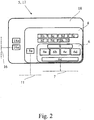
- the PLC computer program 6 can be recognized, which implements various functional blocks, here the end effector function 6a, a feed system 6b of a tool, a workpiece database 6c and safety functions 6d.
- Each such function can be implemented by a separate module in the software technical sense.
- a module bus driver 6e is provided for the telecommunications connection with the module bus 7, a module bus driver 6e is provided.
- the interface to the outside - in the software technical sense - forms the already described above PLC interface. 9
- the cell control computer program 8 addresses the PLC computer program 6 via this PLC interface 9.
- the cell control computer program 8 also has a network bus driver 8a for communication with the network bus 11.
- Other particularly software-technical modules of the cell control computer program 8 are a visualization module 8b, a diagnosis module 8c, a robot module 8d, a normality sensor module 8e, a position sensor module 8f, a laser sensor module 8g and an NC module 8h. These modules communicate with each other. Furthermore, further modules can be provided.
- the PLC computer program 6 and the cell control computer program 8 are executed by different processes, respectively.
- the term process is to be understood here in the software technical sense. In this case, both the PLC computer program 6 and the cell control computer program 8 are each performed by a single process. However, it may also be that the PLC computer program 6 and the cell control computer program 8 are executed by a multiplicity of different processes.
- the division of the PLC computer program 6 and the cell control computer program 8 on the individual processes can be divided into the modules according to the representation of Fig. 2 or a similar distribution, but several modules can be grouped together and executed in a single process. It may also be that some modules are at least partially provided by the operating system, such as the driver.
- a preferred division of the cell control computer program 8 into different processes provides that an NC subcomputer program of the cell control computer program 8 for providing the NC controller 10 is executed in an NC process and that a manipulator subroutine of the cell control computer program 8 for Actuation of the manipulator 2a, b is performed in a manipulator process.
- the manipulator process is different from the NC process.
- the information obtained from the NC commands to control the manipulator 2a, b, ie "cleaned up" of the information for controlling the input-output module 3a, b, can then be processed by the manipulator subroutine.
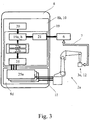
- this NC subroutine for providing the NC controller 10 may - as shown in the Fig. 3 - to the NC module 8h the Fig. 2 and in the manipulator subroutine of the cell control computer program around the robot module 8d of the Fig. 2 act.
- the PLC interface 9 of the PLC computer program 6 can be addressed in principle by any programs and accordingly from different processes. On the one hand, it is addressed by the cell control computer program 8 for activating the input / output module 3a, b, on the other hand data is also made available for retrieval via the SPS interface 9, which is then provided by the visualization module 8b of the cell control computer program 8 can be displayed on a screen of the computing device 5.
- the computing device 5 provide multiple interprocess channels for communication with the PLC computer program 6, with at least partially different prioritization.
- prioritization means the order in which a corresponding communication is processed by the operating system via such an interprocess channel, responding more quickly to communication via an interprocess channel having a higher priority than to communication via an interprocess channel having a lower priority.
- a higher priority task may interrupt a currently processed lower priority task.
- this can be achieved by a single process providing the communication via the interprocess channels and processing these in dependence on the respective priority of the interprocess channels.
- each interprocess channel may be assigned to a process having a priority corresponding to the priority of the interprocess channel, in which case the respective process is processed according to its priority.
- the NC sub-computer program and a visualization program executed in a visualization process each communicate with the PLC computer program 6 via an inter-process channel, and the inter-process channel of the NC sub-computer program is prioritized higher than that of the visualization program. This takes into account the fact that the control by the NC sub-computer program is more important and should be carried out more quickly than a visualization.
- the cell control computer program 6 has an NC processor 19 for translating an NC program 20 into switching commands 21 for driving the input-output module 3a, b.
- the NC processor 19 can also be set up to compile the NC program 20 in geometry data 22a and / or in technology data 22b for controlling the manipulator 2a, b.
- the respective representation of Fig. 3 and the Fig. 4 is complementary insofar as that in the Fig. 3 in the first place the flow of data is represented and in the Fig. 4 the software technical structure of the interfaces is described.
- the NC processor 19 can consist of several modules, each of which is executed in its own process. Alternatively, the NC processor 19 can be executed in total in one process, which may in particular be the above NC process. Thus, the NC processor 19 may be the same as or included in the above NC sub-computer program. Consequently, the NC processor can also be formed by the above NC module 8h.
- the above NC program 20 is now a sequence of NC commands written in plain text. This is also called G-code.
- the G code may include G commands as well as M commands and general parameters.
- the NC processor 19 includes an NC interpreter 19 a and an NC command converter 19 b having access to a command database 23.
- NC interpreter 19a and NC command converter 19b translate the plaintext of the NC program 20 in geometry data 22a and / or technology data 22b on the one hand, for driving the manipulator 2a, b, and switching commands 21 for controlling the input-output module 3a, b on the other hand.
- the generation of the switching commands 21 can also be based on the technology data 22b.
- the NC program 20 can also include references or dependencies on sensor data, so that it is preferably provided that the NC processor 19 is also set up to translate the NC program 20 into sensor queries for reading the sensor device 15a, b.
- the NC processor 19 also includes an NC data collector 19c, which stores automatically generated data records in a protocol database 24 during the execution of the NC program.
- the NC processor 19 executes a path planning calculating routine 25 of the manipulator 2a, b based on the geometry data 22a and / or based on the technology data 22b.
- the path planning executed by the calculation routine 25 preferably comprises a kinematic transformation, that is to say a conversion of Cartesian coordinates into axis coordinates or vice versa.
- the path planning performed by the calculation routine 25 may also include interpolation.
- one or more position controllers 25a of the manipulator 2a can then be supplied with reference variables. This variant corresponds to the representation of Fig. 3 , Deviating from this representation, the calculation routine 25 can also be provided by the robot module 8d.
- this calculation routine 25 performs the above kinematics transformation, but not the path planning.
- a - not shown - robot control of the manipulator 2a, b supplied with the results of the kinematics transformation. Both the path planning and the functionality of the above position controllers 25a are then provided accordingly by this robot controller.
- the NC processor 19 executes the switching commands 21 in which the cell control computer program 8 - whose component is the NC processor 19 - is connected to the PLC interface 9 of the PLC.
- Computer program 6 accesses and the PLC computer program 6 to access the input-output module 3a, b via the module bus 7 drives.
- the NC processor 19 for controlling the manipulator 2a, b preferably also for reading out the sensor device 15a, b in particular also for carrying out the calculation routine 25 accesses an encapsulation interface 26 of the cell control computer program 8, and that access to the manipulator 2a, b via the network bus 11 is controlled. It is further preferred that if necessary also the sensor device 15a, b is read out via the network bus 11 and further, in particular also a path planning is performed on the access.
- Both this access to the encapsulation interface 26 and the access to the PLC interface 9 can be done by means of an object-oriented interface class. Therefore, it is preferred that access to the encapsulation interface 26 and / or the PLC interface 9 accesses an object-oriented interface class 27 of the type of a manipulator class 27a, an input-output module class 27b, a path planning class 27c and / or a sensor class 27d.
- an object-oriented interface class 27 of the type of a manipulator class 27a an input-output module class 27b, a path planning class 27c and / or a sensor class 27d.
- access to the PLC interface 9 may include access to the input-output module class 27b.
- the manipulator class 27a, the input-output module class 27b and / or the sensor class 27d are respectively implemented by a manipulator object 28a, an input-output module object 28b and a sensor object 28d which depends on Type of manipulator 2a, b of the input / output module 3a, b or the sensor device 15a, b is.
- the path planning class 27d may be implemented by a path planning object 28d, which is dependent on the particular algorithms with which path planning and especially interpolation and kinematics transformation is implemented.
Landscapes
- Engineering & Computer Science (AREA)
- Physics & Mathematics (AREA)
- General Physics & Mathematics (AREA)
- Automation & Control Theory (AREA)
- Human Computer Interaction (AREA)
- Manufacturing & Machinery (AREA)
- Numerical Control (AREA)
- Programmable Controllers (AREA)
- Control By Computers (AREA)
- Manipulator (AREA)
Claims (15)
- Procédé d'exploitation d'un système d'automatisation (1), de préférence pour exploiter une cellule d'automatisation (la), comprenant un manipulateur (2a, b) et un module d'entrée/sortie (3a, b) servant à la fabrication automatisée, ainsi qu'un dispositif calculateur (5), dans lequel un logiciel d'automate programmable SPS (6) servant à fournir une commande logique par automate programmable pour le module d'entrée/sortie (3a, b) est exécuté sur le dispositif calculateur (5), le logiciel d'automate programmable SPS (6) étant en communication informatique avec celui-ci pour commander le module d'entrée/sortie (3a, b) par le biais d'un bus de module (7), dans lequel un logiciel de commande de cellule (8) servant à commander le logiciel d'automate programmable SPS (6) par le biais d'une interface SPS (9) du logiciel d'automate programmable SPS (6) est exécuté sur le dispositif calculateur (5), dans lequel le logiciel de commande de cellule (8) fournit une commande numérique NC (10) pour le manipulateur (2a, b), dans lequel le logiciel de commande de cellule (8) communique par une liaison informatique, par le biais d'un bus de réseau (11), avec le manipulateur (2a, b) afin de commander ce dernier,
caractérisé en ce que le logiciel de commande de cellule (8) comporte un processeur NC (19) servant à traduire un programme NC (20) en ordres de commutation (21) afin de commander le module d'entrée/sortie (3a, b) et à traduire un programme NC (20) en données de géométrie (22a) et/ou en données technologiques (22b) afin de commander le manipulateur (2a, b). - Procédé selon la revendication 1, caractérisé en ce que le module d'entrée/sortie (3a, b) comporte un dispositif d'application (12), de préférence un outil, un dispositif de mesure ou un logement, disposé sur le manipulateur (2a, b).
- Procédé selon la revendication 1 ou 2,
caractérisé en ce que le bus de module est un bus de terrain (13) et/ou en ce que le bus de réseau (11) est un bus Ethernet (14), en particulier un bus Ethernet temps réel (14a). - Procédé selon l'une des revendications 1 à 3,
caractérisé en ce que le logiciel de commande de cellule (8) communique par le biais du bus réseau (11) avec un dispositif capteur (15a, b) afin de lire le dispositif capteur (15a, b). - Procédé selon l'une des revendications 1 à 4,
caractérisé en ce que le logiciel de commande de cellule (8) fournit une interface de commande de cellule par le biais d'un bus d'usine (16), bus d'usine (16) avec lequel le logiciel de commande de cellule (8) communique par une liaison informatique. - Procédé selon l'une des revendications 1 à 5,
caractérisé en ce que le dispositif calculateur (5) est un ordinateur personnel (17), de préférence en ce que le logiciel d'automate programmable SPS (6) et le logiciel de commande de cellule (8) s'exécutent sur un système d'exploitation multimédia (18) pour ordinateur personnel (17). - Procédé selon l'une des revendications 1 à 6,
caractérisé en ce que le logiciel d'automate programmable SPS (6) et le logiciel de commande de cellule (8) sont respectivement exécutés par des processus différents. - Procédé selon l'une des revendications 1 à 7,
caractérisé en ce qu'un sous-programme de commande numérique NC du logiciel de commande de cellule (8) servant à fournir la commande numérique (10) est exécuté dans un processus NC et en ce qu'un sous-programme de manipulateur du logiciel de commande de cellule (8) servant à commander le manipulateur (2a,b) est exécuté dans un processus de manipulateur. - Procédé selon la revendication 8,
caractérisé en ce que le dispositif calculateur (5) fournit une pluralité de canaux interprocessus pour la communication avec le logiciel d'automate programmable SPS (6) avec des priorités au moins partiellement différentes, en ce que le sous- programme NC et un programme de visualisation exécuté dans un processus de visualisation communiquent de préférence respectivement avec le logiciel d'automate programmable SPS (6) par le biais d'un canal interprocessus et en ce que le canal interprocessus du sous-programme NC présente une priorité supérieure à celle du programme de visualisation. - Procédé selon la revendication 4 et l'une des revendications 5 à 9 lorsqu'elles font référence à la revendication 4, caractérisé en ce que le processeur NC (19) est prévu pour traduire le programme NC (20) en requêtes de capteur servant à la lecture du dispositif capteur (15a,b).
- Procédé selon la revendication 10, caractérisé en ce que le processeur NC exécute une routine de calcul (25) servant à la planification de trajectoire du manipulateur (2a, b), comprenant de préférence une transformation cinématique et/ou une interpolation, sur la base des données géométriques (22a) et/ou des données techniques (22b).
- Procédé selon la revendication 10 ou 11,
caractérisé en ce que le processeur NC (19) exécute les ordres de commutation (21), en faisant en sorte que le logiciel de commande de cellule (8) accède à l'interface SPS (9) du logiciel d'automate programmable SPS (6) et que le logiciel d'automate programmable SPS (6) commande le module d'entrée/sortie (3a,b) lors dudit accès, par le biais du bus de module (7). - Procédé selon la revendication 11 et la revendication 12, lorsqu'elles font référence à la revendication 11, caractérisé en ce que le processeur NC (19) accède à une interface d'encapsulation (26) du logiciel de commande de cellule (8) pour la commande du manipulateur (2a,b), de préférence également pour la lecture du dispositif capteur (15a, b), notamment également pour exécuter la routine de calcul (25),
et en ce que, lors de l'accès, le manipulateur (2a, b) est commandé par le biais du bus de réseau (11), le dispositif capteur (15a, b) est également de préférence si nécessaire lu par le biais du bus de réseau (11), et une planification de trajectoire est également effectuée si nécessaire. - Procédé selon la revendication 13, caractérisé en ce que l'accès à l'interface d'encapsulation (26) et/ou à l'interface SPS (9) comprend l'accès à une classe d'interfaces orientée objet (27) du type d'une classe de manipulateur (27a), d'une classe de module d'entrée/sortie (27b), d'une classe de capteur (27c) et/ou d'une classe de planification de trajectoire (27d) .
- Procédé selon la revendication 14, caractérisé en ce que la classe de manipulateur (27a), la classe de module d'entrée/sortie (27b) et/ou la classe de capteur (27c) sont respectivement mises en œuvre par un objet manipulateur (28a), par un objet module d'entrée-sortie (28b) ou par un objet capteur (28c) qui est fonction du type du manipulateur (2a,b), du module d'entrée/sortie (3a, b) ou du dispositif capteur (15a, b).
Applications Claiming Priority (2)
| Application Number | Priority Date | Filing Date | Title |
|---|---|---|---|
| DE102014105381.8A DE102014105381A1 (de) | 2014-04-15 | 2014-04-15 | Verfahren zum Betrieb einer Automatisierungsanordnung |
| PCT/EP2015/058146 WO2015158763A1 (fr) | 2014-04-15 | 2015-04-15 | Procédé d'exploitation d'un système d'automatisation |
Publications (2)
| Publication Number | Publication Date |
|---|---|
| EP3132319A1 EP3132319A1 (fr) | 2017-02-22 |
| EP3132319B1 true EP3132319B1 (fr) | 2019-11-06 |
Family
ID=52997422
Family Applications (1)
| Application Number | Title | Priority Date | Filing Date |
|---|---|---|---|
| EP15717855.9A Active EP3132319B1 (fr) | 2014-04-15 | 2015-04-15 | Procédé d'exploitation d'un système d'automatisation |
Country Status (6)
| Country | Link |
|---|---|
| US (1) | US10678191B2 (fr) |
| EP (1) | EP3132319B1 (fr) |
| CN (1) | CN106415417B (fr) |
| DE (1) | DE102014105381A1 (fr) |
| RU (1) | RU2660332C2 (fr) |
| WO (1) | WO2015158763A1 (fr) |
Families Citing this family (3)
| Publication number | Priority date | Publication date | Assignee | Title |
|---|---|---|---|---|
| DE102014105381A1 (de) | 2014-04-15 | 2015-10-15 | Brötje-Automation GmbH | Verfahren zum Betrieb einer Automatisierungsanordnung |
| DE102018112647B4 (de) * | 2018-05-25 | 2021-11-18 | Franka Emika Gmbh | Verfahren zum Betreiben eines Roboters mittels eines speziellen Prozesskalküls |
| DE102022209987B3 (de) | 2022-09-22 | 2023-08-10 | Thyssenkrupp Ag | Fertigungsanlage sowie Verfahren zum Betreiben einer Fertigungsanlage mit einem Roboter und einer speicherprogrammierbaren Steuerung mit relativer Adressierung |
Family Cites Families (13)
| Publication number | Priority date | Publication date | Assignee | Title |
|---|---|---|---|---|
| DE19634279A1 (de) * | 1996-08-24 | 1998-02-26 | Bosch Gmbh Robert | Verfahren und Einrichtung zur beschleunigten Ausführung eines Programmes durch eine speicherprogrammierbare Steuerung |
| CN1093454C (zh) * | 1996-11-07 | 2002-10-30 | 大隈株式会社 | 数字控制命令发生器及其方法 |
| JP2001350510A (ja) * | 2000-06-06 | 2001-12-21 | Mori Seiki Co Ltd | 工作機械保守管理システム |
| JP3827092B2 (ja) | 2003-10-22 | 2006-09-27 | オムロン株式会社 | 制御システム設定装置および制御システム設定方法ならびに設定プログラム |
| DE10357824A1 (de) * | 2003-12-09 | 2005-07-14 | Kuka Roboter Gmbh | Verfahren und Vorrichtung zum Betreiben zusammenarbeitender unterschiedlicher Geräte |
| US7269464B2 (en) | 2004-04-13 | 2007-09-11 | Siemens Energy & Automation, Inc. | System, method and computer program product for providing an interface for instantiating additional programmable logic controller functionality |
| CN101226388A (zh) * | 2008-02-01 | 2008-07-23 | 哈尔滨工业大学 | 开放式软件化数控系统 |
| CN101226385A (zh) * | 2008-02-01 | 2008-07-23 | 哈尔滨工业大学 | 开放式软数控系统的软plc模块 |
| DE102008010301A1 (de) * | 2008-02-21 | 2009-09-03 | Liebherr-Verzahntechnik Gmbh | Verfahren zum Betrieb einer Verzahnungsschleifmaschine |
| CN201421670Y (zh) * | 2009-04-01 | 2010-03-10 | 苏州市职业大学 | 一种软可编程序控制器 |
| CN102390071A (zh) * | 2011-09-30 | 2012-03-28 | 佛山市顺德工业与信息技术研究中心有限公司 | 基于网络控制的木材加工柔性化生产系统 |
| JP6310076B2 (ja) * | 2013-07-30 | 2018-04-11 | Dmg森精機株式会社 | 数値制御工作機械の操作を制御するための制御システム、およびそのようなシステムで使用するためのバックエンドとフロントエンド制御装置 |
| DE102014105381A1 (de) | 2014-04-15 | 2015-10-15 | Brötje-Automation GmbH | Verfahren zum Betrieb einer Automatisierungsanordnung |
-
2014
- 2014-04-15 DE DE102014105381.8A patent/DE102014105381A1/de active Pending
-
2015
- 2015-04-15 WO PCT/EP2015/058146 patent/WO2015158763A1/fr not_active Ceased
- 2015-04-15 CN CN201580032137.8A patent/CN106415417B/zh active Active
- 2015-04-15 RU RU2016144485A patent/RU2660332C2/ru active
- 2015-04-15 EP EP15717855.9A patent/EP3132319B1/fr active Active
- 2015-04-15 US US15/304,143 patent/US10678191B2/en active Active
Non-Patent Citations (1)
| Title |
|---|
| None * |
Also Published As
| Publication number | Publication date |
|---|---|
| US10678191B2 (en) | 2020-06-09 |
| RU2016144485A (ru) | 2018-05-15 |
| DE102014105381A1 (de) | 2015-10-15 |
| RU2660332C2 (ru) | 2018-07-05 |
| CN106415417B (zh) | 2020-07-03 |
| EP3132319A1 (fr) | 2017-02-22 |
| US20170038745A1 (en) | 2017-02-09 |
| RU2016144485A3 (fr) | 2018-05-15 |
| CN106415417A (zh) | 2017-02-15 |
| WO2015158763A1 (fr) | 2015-10-22 |
Similar Documents
| Publication | Publication Date | Title |
|---|---|---|
| DE102011108282B4 (de) | Numerische Steuerung für eine Mehrachsenmaschine zum Bearbeiten einer geneigten Bearbeitungsebene | |
| EP0524344B1 (fr) | Commande de machine-outil configurable | |
| EP1248966B1 (fr) | Commande cinematique universelle | |
| DE20004370U1 (de) | Industrielle Produktionsanlage mit WEB-Steuersystem | |
| DE102004025875A1 (de) | Funktionsblock mit Boolescher Logik | |
| DE4411426B4 (de) | Multitask-Steuersystem | |
| DE102012112900A1 (de) | Numerische Steuerungsprogrammausrichtung durch Roboter | |
| EP2324966B1 (fr) | Procédé et dispositif destinés à la planification et/ou à la commande d'une application de robot | |
| EP2837981B1 (fr) | Procédé et dispositif de configuration automatisée d'une fonction de surveillance d'un robot industriel | |
| EP2353051A1 (fr) | Procédé et dispositif pour établir un programme utilisateur pour une commande de sécurité | |
| EP1402325B1 (fr) | Procede et systeme pour soutenir les projets de construction d'usines | |
| DE102013100465A1 (de) | Mikroprozessor-gesteuerte Steuerungseinrichtung für eine Spritzgiessanlage | |
| EP0553621B1 (fr) | Commande programmable par ordinateur pour une machine outil | |
| EP3132319B1 (fr) | Procédé d'exploitation d'un système d'automatisation | |
| DE10393527T5 (de) | Systeme und Verfahren zur Darstellung komplexer n-Kurven für die Direktsteuerung einer Werkzeugbewegung | |
| AT522653B1 (de) | Verfahren zur Darstellung und Bedienung von Produktionsmitteln, insbesondere für die kunststoffverarbeitende Industrie | |
| EP2345511A2 (fr) | Commande pour un manipulateur | |
| EP0903654A2 (fr) | Système de commande, en particulier pour une installation de pallettisation comprenant un robot | |
| DE10357824A1 (de) | Verfahren und Vorrichtung zum Betreiben zusammenarbeitender unterschiedlicher Geräte | |
| DE112021005212T5 (de) | Numerik-Steuersystem und Verfahren zur Steuerung einer Industriemaschine | |
| DE10065418A1 (de) | Integrationsverfahren für Automatisierungskomponenten | |
| DE102016121788A1 (de) | Konfiguration einer Automatisierungsanlage | |
| EP1195667B1 (fr) | Commande cinématique universelle | |
| DE102007007601A1 (de) | Vorrichtung zur Herstellung eines Steuerprogramms aus Funktionsmodulen, mehrachsige Maschine, Verfahren und graphische Benutzerschnittstelle | |
| DE10155586A1 (de) | Automatisierungssystem, Technologiefunktionsplattform, Verfahren zum Betrieb eines Automatisierungssystems und Verwendung einer Technologiefunktionsplattform |
Legal Events
| Date | Code | Title | Description |
|---|---|---|---|
| STAA | Information on the status of an ep patent application or granted ep patent |
Free format text: STATUS: THE INTERNATIONAL PUBLICATION HAS BEEN MADE |
|
| PUAI | Public reference made under article 153(3) epc to a published international application that has entered the european phase |
Free format text: ORIGINAL CODE: 0009012 |
|
| STAA | Information on the status of an ep patent application or granted ep patent |
Free format text: STATUS: REQUEST FOR EXAMINATION WAS MADE |
|
| 17P | Request for examination filed |
Effective date: 20161027 |
|
| AK | Designated contracting states |
Kind code of ref document: A1 Designated state(s): AL AT BE BG CH CY CZ DE DK EE ES FI FR GB GR HR HU IE IS IT LI LT LU LV MC MK MT NL NO PL PT RO RS SE SI SK SM TR |
|
| AX | Request for extension of the european patent |
Extension state: BA ME |
|
| DAV | Request for validation of the european patent (deleted) | ||
| DAX | Request for extension of the european patent (deleted) | ||
| GRAP | Despatch of communication of intention to grant a patent |
Free format text: ORIGINAL CODE: EPIDOSNIGR1 |
|
| STAA | Information on the status of an ep patent application or granted ep patent |
Free format text: STATUS: GRANT OF PATENT IS INTENDED |
|
| INTG | Intention to grant announced |
Effective date: 20190705 |
|
| GRAS | Grant fee paid |
Free format text: ORIGINAL CODE: EPIDOSNIGR3 |
|
| GRAA | (expected) grant |
Free format text: ORIGINAL CODE: 0009210 |
|
| STAA | Information on the status of an ep patent application or granted ep patent |
Free format text: STATUS: THE PATENT HAS BEEN GRANTED |
|
| AK | Designated contracting states |
Kind code of ref document: B1 Designated state(s): AL AT BE BG CH CY CZ DE DK EE ES FI FR GB GR HR HU IE IS IT LI LT LU LV MC MK MT NL NO PL PT RO RS SE SI SK SM TR |
|
| REG | Reference to a national code |
Ref country code: GB Ref legal event code: FG4D Free format text: NOT ENGLISH |
|
| REG | Reference to a national code |
Ref country code: CH Ref legal event code: EP Ref country code: AT Ref legal event code: REF Ref document number: 1199621 Country of ref document: AT Kind code of ref document: T Effective date: 20191115 |
|
| REG | Reference to a national code |
Ref country code: IE Ref legal event code: FG4D Free format text: LANGUAGE OF EP DOCUMENT: GERMAN |
|
| REG | Reference to a national code |
Ref country code: DE Ref legal event code: R096 Ref document number: 502015010856 Country of ref document: DE |
|
| REG | Reference to a national code |
Ref country code: NL Ref legal event code: MP Effective date: 20191106 |
|
| REG | Reference to a national code |
Ref country code: LT Ref legal event code: MG4D |
|
| PG25 | Lapsed in a contracting state [announced via postgrant information from national office to epo] |
Ref country code: SE Free format text: LAPSE BECAUSE OF FAILURE TO SUBMIT A TRANSLATION OF THE DESCRIPTION OR TO PAY THE FEE WITHIN THE PRESCRIBED TIME-LIMIT Effective date: 20191106 Ref country code: LV Free format text: LAPSE BECAUSE OF FAILURE TO SUBMIT A TRANSLATION OF THE DESCRIPTION OR TO PAY THE FEE WITHIN THE PRESCRIBED TIME-LIMIT Effective date: 20191106 Ref country code: PT Free format text: LAPSE BECAUSE OF FAILURE TO SUBMIT A TRANSLATION OF THE DESCRIPTION OR TO PAY THE FEE WITHIN THE PRESCRIBED TIME-LIMIT Effective date: 20200306 Ref country code: PL Free format text: LAPSE BECAUSE OF FAILURE TO SUBMIT A TRANSLATION OF THE DESCRIPTION OR TO PAY THE FEE WITHIN THE PRESCRIBED TIME-LIMIT Effective date: 20191106 Ref country code: LT Free format text: LAPSE BECAUSE OF FAILURE TO SUBMIT A TRANSLATION OF THE DESCRIPTION OR TO PAY THE FEE WITHIN THE PRESCRIBED TIME-LIMIT Effective date: 20191106 Ref country code: NL Free format text: LAPSE BECAUSE OF FAILURE TO SUBMIT A TRANSLATION OF THE DESCRIPTION OR TO PAY THE FEE WITHIN THE PRESCRIBED TIME-LIMIT Effective date: 20191106 Ref country code: GR Free format text: LAPSE BECAUSE OF FAILURE TO SUBMIT A TRANSLATION OF THE DESCRIPTION OR TO PAY THE FEE WITHIN THE PRESCRIBED TIME-LIMIT Effective date: 20200207 Ref country code: NO Free format text: LAPSE BECAUSE OF FAILURE TO SUBMIT A TRANSLATION OF THE DESCRIPTION OR TO PAY THE FEE WITHIN THE PRESCRIBED TIME-LIMIT Effective date: 20200206 Ref country code: BG Free format text: LAPSE BECAUSE OF FAILURE TO SUBMIT A TRANSLATION OF THE DESCRIPTION OR TO PAY THE FEE WITHIN THE PRESCRIBED TIME-LIMIT Effective date: 20200206 Ref country code: FI Free format text: LAPSE BECAUSE OF FAILURE TO SUBMIT A TRANSLATION OF THE DESCRIPTION OR TO PAY THE FEE WITHIN THE PRESCRIBED TIME-LIMIT Effective date: 20191106 |
|
| PG25 | Lapsed in a contracting state [announced via postgrant information from national office to epo] |
Ref country code: HR Free format text: LAPSE BECAUSE OF FAILURE TO SUBMIT A TRANSLATION OF THE DESCRIPTION OR TO PAY THE FEE WITHIN THE PRESCRIBED TIME-LIMIT Effective date: 20191106 Ref country code: RS Free format text: LAPSE BECAUSE OF FAILURE TO SUBMIT A TRANSLATION OF THE DESCRIPTION OR TO PAY THE FEE WITHIN THE PRESCRIBED TIME-LIMIT Effective date: 20191106 Ref country code: IS Free format text: LAPSE BECAUSE OF FAILURE TO SUBMIT A TRANSLATION OF THE DESCRIPTION OR TO PAY THE FEE WITHIN THE PRESCRIBED TIME-LIMIT Effective date: 20200306 |
|
| PG25 | Lapsed in a contracting state [announced via postgrant information from national office to epo] |
Ref country code: AL Free format text: LAPSE BECAUSE OF FAILURE TO SUBMIT A TRANSLATION OF THE DESCRIPTION OR TO PAY THE FEE WITHIN THE PRESCRIBED TIME-LIMIT Effective date: 20191106 |
|
| PG25 | Lapsed in a contracting state [announced via postgrant information from national office to epo] |
Ref country code: RO Free format text: LAPSE BECAUSE OF FAILURE TO SUBMIT A TRANSLATION OF THE DESCRIPTION OR TO PAY THE FEE WITHIN THE PRESCRIBED TIME-LIMIT Effective date: 20191106 Ref country code: CZ Free format text: LAPSE BECAUSE OF FAILURE TO SUBMIT A TRANSLATION OF THE DESCRIPTION OR TO PAY THE FEE WITHIN THE PRESCRIBED TIME-LIMIT Effective date: 20191106 Ref country code: ES Free format text: LAPSE BECAUSE OF FAILURE TO SUBMIT A TRANSLATION OF THE DESCRIPTION OR TO PAY THE FEE WITHIN THE PRESCRIBED TIME-LIMIT Effective date: 20191106 Ref country code: DK Free format text: LAPSE BECAUSE OF FAILURE TO SUBMIT A TRANSLATION OF THE DESCRIPTION OR TO PAY THE FEE WITHIN THE PRESCRIBED TIME-LIMIT Effective date: 20191106 Ref country code: EE Free format text: LAPSE BECAUSE OF FAILURE TO SUBMIT A TRANSLATION OF THE DESCRIPTION OR TO PAY THE FEE WITHIN THE PRESCRIBED TIME-LIMIT Effective date: 20191106 |
|
| REG | Reference to a national code |
Ref country code: DE Ref legal event code: R097 Ref document number: 502015010856 Country of ref document: DE |
|
| PG25 | Lapsed in a contracting state [announced via postgrant information from national office to epo] |
Ref country code: SK Free format text: LAPSE BECAUSE OF FAILURE TO SUBMIT A TRANSLATION OF THE DESCRIPTION OR TO PAY THE FEE WITHIN THE PRESCRIBED TIME-LIMIT Effective date: 20191106 Ref country code: SM Free format text: LAPSE BECAUSE OF FAILURE TO SUBMIT A TRANSLATION OF THE DESCRIPTION OR TO PAY THE FEE WITHIN THE PRESCRIBED TIME-LIMIT Effective date: 20191106 |
|
| PLBE | No opposition filed within time limit |
Free format text: ORIGINAL CODE: 0009261 |
|
| STAA | Information on the status of an ep patent application or granted ep patent |
Free format text: STATUS: NO OPPOSITION FILED WITHIN TIME LIMIT |
|
| 26N | No opposition filed |
Effective date: 20200807 |
|
| PG25 | Lapsed in a contracting state [announced via postgrant information from national office to epo] |
Ref country code: MC Free format text: LAPSE BECAUSE OF FAILURE TO SUBMIT A TRANSLATION OF THE DESCRIPTION OR TO PAY THE FEE WITHIN THE PRESCRIBED TIME-LIMIT Effective date: 20191106 Ref country code: SI Free format text: LAPSE BECAUSE OF FAILURE TO SUBMIT A TRANSLATION OF THE DESCRIPTION OR TO PAY THE FEE WITHIN THE PRESCRIBED TIME-LIMIT Effective date: 20191106 |
|
| REG | Reference to a national code |
Ref country code: CH Ref legal event code: PL |
|
| PG25 | Lapsed in a contracting state [announced via postgrant information from national office to epo] |
Ref country code: FR Free format text: LAPSE BECAUSE OF NON-PAYMENT OF DUE FEES Effective date: 20200430 Ref country code: CH Free format text: LAPSE BECAUSE OF NON-PAYMENT OF DUE FEES Effective date: 20200430 Ref country code: LI Free format text: LAPSE BECAUSE OF NON-PAYMENT OF DUE FEES Effective date: 20200430 Ref country code: IT Free format text: LAPSE BECAUSE OF FAILURE TO SUBMIT A TRANSLATION OF THE DESCRIPTION OR TO PAY THE FEE WITHIN THE PRESCRIBED TIME-LIMIT Effective date: 20191106 Ref country code: LU Free format text: LAPSE BECAUSE OF NON-PAYMENT OF DUE FEES Effective date: 20200415 |
|
| REG | Reference to a national code |
Ref country code: BE Ref legal event code: MM Effective date: 20200430 |
|
| PG25 | Lapsed in a contracting state [announced via postgrant information from national office to epo] |
Ref country code: BE Free format text: LAPSE BECAUSE OF NON-PAYMENT OF DUE FEES Effective date: 20200430 |
|
| GBPC | Gb: european patent ceased through non-payment of renewal fee |
Effective date: 20200415 |
|
| PG25 | Lapsed in a contracting state [announced via postgrant information from national office to epo] |
Ref country code: GB Free format text: LAPSE BECAUSE OF NON-PAYMENT OF DUE FEES Effective date: 20200415 Ref country code: IE Free format text: LAPSE BECAUSE OF NON-PAYMENT OF DUE FEES Effective date: 20200415 |
|
| REG | Reference to a national code |
Ref country code: AT Ref legal event code: MM01 Ref document number: 1199621 Country of ref document: AT Kind code of ref document: T Effective date: 20200415 |
|
| PG25 | Lapsed in a contracting state [announced via postgrant information from national office to epo] |
Ref country code: AT Free format text: LAPSE BECAUSE OF NON-PAYMENT OF DUE FEES Effective date: 20200415 |
|
| PG25 | Lapsed in a contracting state [announced via postgrant information from national office to epo] |
Ref country code: TR Free format text: LAPSE BECAUSE OF FAILURE TO SUBMIT A TRANSLATION OF THE DESCRIPTION OR TO PAY THE FEE WITHIN THE PRESCRIBED TIME-LIMIT Effective date: 20191106 Ref country code: MT Free format text: LAPSE BECAUSE OF FAILURE TO SUBMIT A TRANSLATION OF THE DESCRIPTION OR TO PAY THE FEE WITHIN THE PRESCRIBED TIME-LIMIT Effective date: 20191106 Ref country code: CY Free format text: LAPSE BECAUSE OF FAILURE TO SUBMIT A TRANSLATION OF THE DESCRIPTION OR TO PAY THE FEE WITHIN THE PRESCRIBED TIME-LIMIT Effective date: 20191106 |
|
| PG25 | Lapsed in a contracting state [announced via postgrant information from national office to epo] |
Ref country code: MK Free format text: LAPSE BECAUSE OF FAILURE TO SUBMIT A TRANSLATION OF THE DESCRIPTION OR TO PAY THE FEE WITHIN THE PRESCRIBED TIME-LIMIT Effective date: 20191106 |
|
| PGFP | Annual fee paid to national office [announced via postgrant information from national office to epo] |
Ref country code: DE Payment date: 20250429 Year of fee payment: 11 |