EP3132459B1 - Eingebettetes polteil zur mittel- oder hochspannungsverwendung mit einem vakuumschalter, der in einem isolierenden harz eingebettet ist - Google Patents
Eingebettetes polteil zur mittel- oder hochspannungsverwendung mit einem vakuumschalter, der in einem isolierenden harz eingebettet ist Download PDFInfo
- Publication number
- EP3132459B1 EP3132459B1 EP14786600.8A EP14786600A EP3132459B1 EP 3132459 B1 EP3132459 B1 EP 3132459B1 EP 14786600 A EP14786600 A EP 14786600A EP 3132459 B1 EP3132459 B1 EP 3132459B1
- Authority
- EP
- European Patent Office
- Prior art keywords
- pole part
- embedded
- insulating resin
- metal grid
- sensor
- Prior art date
- Legal status (The legal status is an assumption and is not a legal conclusion. Google has not performed a legal analysis and makes no representation as to the accuracy of the status listed.)
- Active
Links
Images

Classifications
-
- H—ELECTRICITY
- H01—ELECTRIC ELEMENTS
- H01H—ELECTRIC SWITCHES; RELAYS; SELECTORS; EMERGENCY PROTECTIVE DEVICES
- H01H33/00—High-tension or heavy-current switches with arc-extinguishing or arc-preventing means
- H01H33/02—Details
- H01H33/027—Integrated apparatus for measuring current or voltage
-
- H—ELECTRICITY
- H01—ELECTRIC ELEMENTS
- H01H—ELECTRIC SWITCHES; RELAYS; SELECTORS; EMERGENCY PROTECTIVE DEVICES
- H01H33/00—High-tension or heavy-current switches with arc-extinguishing or arc-preventing means
- H01H33/60—Switches wherein the means for extinguishing or preventing the arc do not include separate means for obtaining or increasing flow of arc-extinguishing fluid
- H01H33/66—Vacuum switches
- H01H33/6606—Terminal arrangements
-
- H—ELECTRICITY
- H01—ELECTRIC ELEMENTS
- H01H—ELECTRIC SWITCHES; RELAYS; SELECTORS; EMERGENCY PROTECTIVE DEVICES
- H01H33/00—High-tension or heavy-current switches with arc-extinguishing or arc-preventing means
- H01H33/60—Switches wherein the means for extinguishing or preventing the arc do not include separate means for obtaining or increasing flow of arc-extinguishing fluid
- H01H33/66—Vacuum switches
- H01H33/662—Housings or protective screens
- H01H33/66207—Specific housing details, e.g. sealing, soldering or brazing
-
- H—ELECTRICITY
- H01—ELECTRIC ELEMENTS
- H01H—ELECTRIC SWITCHES; RELAYS; SELECTORS; EMERGENCY PROTECTIVE DEVICES
- H01H33/00—High-tension or heavy-current switches with arc-extinguishing or arc-preventing means
- H01H33/60—Switches wherein the means for extinguishing or preventing the arc do not include separate means for obtaining or increasing flow of arc-extinguishing fluid
- H01H33/66—Vacuum switches
- H01H33/662—Housings or protective screens
- H01H33/66207—Specific housing details, e.g. sealing, soldering or brazing
- H01H2033/6623—Details relating to the encasing or the outside layers of the vacuum switch housings
Definitions
- the invention relates to an embedded pole part for medium or high voltage use, with a vacuum interrupter which is embedded into an insulating resin, wherein a current and/or voltage sensor is integrated inside the insulating resin, according to the preamble of claim 1, and method of producing the same.
- the external surface of the coil is covered with semiconducting layer, which works as shielding for the internal coil at the same time works as the electrode of capacitive voltage sensor to high voltage primary
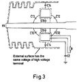
- the problem is, that the voltage measurement accuracy of integrated current and/or voltage sensors will change with changing insulating resin surface conditions, for example as effected by external humidity, and the parasitic capacitance could change.
- This parasitic capacitance will also change the capacitance for measurement. Therefore the change of the measurement is shown in Figure. 3-4 as state of the art.
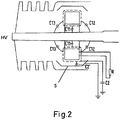
- the measurement capacitance C1 could have four components, C11 between the inner coil surface to primary conductor with high voltage (HV), left and right coil surface to primary conductor capacitance C12 and C13, and from the external surface C14 to primary conductor.
- the capacitance C2 is constant.
- the measurement capacitance is better defined and the value will not change with external environments.
- the measurement capacitance are sum of C11, C12, C13.
- the capacitance of external surface of coil to the grounded metal grid is also constant and no more component for capacitance C1 instead as component of capacitance C2.
- the form and dimension is designed in such a way, that the parasitic capacitance from the measuring capacitance electrode to the external surface of insulation resin is minimized and limited as shown in Figure 2 .
- the metal grid is electrically conductive or capacitively connected to earth potential.
- a further advantageous embodiment is, that the metal grid is arranged around the sensor housing but completely inside the resin, as separated steps in production, which is highly advantageous.
- the metal grid is connected to earth potential via an electrical conductive wire, which is aligned along its path from the metal grid to the earth potential around the shielded signal cables of the current and/or the voltage sensor in a spiral way.
- This conductive wire is electrically connected to the shielding of the shielded signal cable and will be earthen or earthened to the main ground electrically or capacitively.
- the voltage sensor is applied at the line side of the pole part.
- the metal grid has an at least partly cylindrical form, or a C- or L-shaped form.
- the width of the metal grid plays very important role, normally it should be no less than the width of the capacitive electrode.
- the invention is, that the sensor, electrode and corresponding shielded cable, which connects to the current transformer and the electrode, are molded in insulating resin as first step, and then the metal grid is assembled to the molded subassembly and then electrically connected to the shielded cable in a final step.
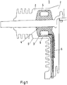
- FIG. 1 displays an embodiment of the invention.
- a current transformer CT is arranged around the conductor of a pole part, the external surface of this current transformer is used as capacitance sensor which results effectively in a voltage sensor 3. So the current transformer, capacitive voltage sensor and the conductor are embedded in an insulation resin, which is the effective voltage sensor housing 4 as first production step. This allows to check the current and voltage sensor properties separately.
- a metal grid 5 is assembled around the produced subassembly and that metal grid is connected to ground potential through the shielding of the signal cable as described above.
- the current sensor, capacitive sensor electrode and corresponding shielded cable which connects to the CT and the capacitive electrode are molded in insulating resin as first step.
- This component could be functionally checked before embedding in the complete pole part 1.
- the metal grid is asseambled to the molded subasseambly and then electrically connected to the shielded cable.
- this is embedded together with the vacuum interrupter within the final molding process.
Landscapes
- Measuring Instrument Details And Bridges, And Automatic Balancing Devices (AREA)
- Transformers For Measuring Instruments (AREA)
Claims (7)
- Eingebettetes Polteil (1) zur Mittel- oder Hochspannungsverwendung, das einen Vakuumschalter einschließt, der in ein isolierendes Harz (2) eingebettet ist, wobei ein Strom- und/oder Spannungssensor (3) mit Sensorgehäuse (4) in das isolierende Harz (2) integriert ist,
dadurch gekennzeichnet, dass ein Metallgitter (5) in das isolierende Harz (2) implementiert worden ist, das zwischen dem Sensorgehäuse (4) des Strom- und/oder Spannungssensors (3) und der Außenseite des isolierenden Harzes (6) angeordnet ist. - Eingebettetes Polteil nach Anspruch 1, dadurch gekennzeichnet, dass das Metallgitter (5) elektrisch leitfähig oder kapazitiv mit Erdpotential verbunden ist.
- Eingebettetes Polteil nach Anspruch 1, dadurch gekennzeichnet, dass das Metallgitter (5) um das Sensorgehäuse (4) herum angeordnet ist.
- Eingebettetes Polteil nach Anspruch 2 oder 3, dadurch gekennzeichnet, dass das Metallgitter (5) über ein elektrisch leitfähiges Kabel mit Erdpotential verbunden ist, welches entlang seines Wegs von dem Metallgitter zu dem Erdpotential in spiraliger Weise um die Signalkabel des Strom- und/oder Spannungssensors geführt ist.
- Eingebettetes Polteil nach einem der vorhergehenden Ansprüche, dadurch gekennzeichnet, dass der Spannungssensor (3) an der Leitungsseite des Polteils (1) angebracht ist.
- Eingebettetes Polteil nach einem der vorhergehenden Ansprüche, dadurch gekennzeichnet, dass das Metallgitter, um gute Funktion zu erreichen, eine mindestens teilweise zylindrische Form oder eine C- oder L-förmige Form aufweist.
- Verfahren zur Herstellung eines eingebetteten Polteils (1) zur Mittel- oder Hochspannungsverwendung, das einen Vakuumschalter einschließt, der in ein isolierendes Harz (2) eingebettet ist, wobei ein Strom- und/oder Spannungssensor (3) mit Sensorgehäuse (4) in das isolierende Harz (2) integriert ist, dadurch gekennzeichnet,
dass der Strom- und/oder Spannungssensor (3), eine Sensorelektrode und ein entsprechend abgeschirmtes Kabel, das mit einem Transformator und der Elektrode des Sensors (3) verbunden ist, in einem ersten Schritt in das isolierende Harz geformt werden, und
dann das Metallgitter um die geformte Teilanordnung herum montiert und dann in einem letzten Schritt elektrisch mit dem abgeschirmten Kabel verbunden wird.
Applications Claiming Priority (2)
| Application Number | Priority Date | Filing Date | Title |
|---|---|---|---|
| EP14001354 | 2014-04-14 | ||
| PCT/EP2014/002264 WO2015158357A1 (en) | 2014-04-14 | 2014-08-18 | Embedded pole part for medium or high voltage use, with a vacuum interrupter which is embedded into an insulating resin |
Publications (2)
| Publication Number | Publication Date |
|---|---|
| EP3132459A1 EP3132459A1 (de) | 2017-02-22 |
| EP3132459B1 true EP3132459B1 (de) | 2018-08-15 |
Family
ID=50513640
Family Applications (1)
| Application Number | Title | Priority Date | Filing Date |
|---|---|---|---|
| EP14786600.8A Active EP3132459B1 (de) | 2014-04-14 | 2014-08-18 | Eingebettetes polteil zur mittel- oder hochspannungsverwendung mit einem vakuumschalter, der in einem isolierenden harz eingebettet ist |
Country Status (5)
| Country | Link |
|---|---|
| US (1) | US10460893B2 (de) |
| EP (1) | EP3132459B1 (de) |
| CN (1) | CN106170843B (de) |
| ES (1) | ES2695170T3 (de) |
| WO (1) | WO2015158357A1 (de) |
Families Citing this family (4)
| Publication number | Priority date | Publication date | Assignee | Title |
|---|---|---|---|---|
| CN109239439B (zh) * | 2018-10-16 | 2024-09-03 | 国网江苏省电力有限公司南京供电分公司 | 一种嵌入式电压传感器 |
| US11385263B2 (en) * | 2018-10-18 | 2022-07-12 | S&C Electric Company | Capacitive voltage sensor with a hidden sensing electrode |
| GB2588631B (en) * | 2019-10-29 | 2022-03-23 | Tavrida Electric Holding Ag | Voltage sensor for electrical switchgear and electrical switchgear comprising same |
| EP4467989A1 (de) * | 2023-05-23 | 2024-11-27 | Abb Schweiz Ag | Mittel- oder hochspannungs-instrumentspannungswandler |
Family Cites Families (16)
| Publication number | Priority date | Publication date | Assignee | Title |
|---|---|---|---|---|
| DE3112776C2 (de) * | 1981-03-31 | 1986-05-22 | Wickmann-Werke Böblingen GmbH, 7030 Böblingen | Mittelspannungs-Schaltvorrichtung mit einem Vakuum-Unterbrecher zwischen einer Sammelschiene und einem Kabelanschlußstutzen |
| US4808121A (en) * | 1988-02-24 | 1989-02-28 | Preformed Line Products Company | Bond connector for service cable |
| FR2683940B1 (fr) * | 1991-11-20 | 1993-12-31 | Gec Alsthom Sa | Disjoncteur a moyenne tension pour l'interieur ou l'exterieur. |
| AU6823594A (en) * | 1993-04-29 | 1994-11-21 | Lindsey Manufacturing Company | Integrated electrical system |
| WO1995027298A1 (en) | 1994-03-31 | 1995-10-12 | Abb Power T & D Company Inc. | Interrupter assembly |
| US5585611A (en) | 1994-03-31 | 1996-12-17 | Abb Power T&D Company Inc. | Interrupter assembly |
| US6538422B2 (en) * | 2000-04-26 | 2003-03-25 | S & C Electric Co. | Voltage sensor bushing assembly with integral capacitance screen |
| US6529013B2 (en) * | 2001-05-31 | 2003-03-04 | Mcgraw-Edison Company | Three-phase voltage sensor with active crosstalk cancellation |
| US6888086B2 (en) * | 2002-09-30 | 2005-05-03 | Cooper Technologies Company | Solid dielectric encapsulated interrupter |
| US20050082260A1 (en) * | 2003-10-15 | 2005-04-21 | G&W Electric Co. | Shielded encapsulated vacuum interrupter |
| AU2005262428B2 (en) | 2004-06-21 | 2009-02-19 | Abb Schweiz Ag | A method and an apparatus for measuring voltage at a power switching device |
| US7837495B2 (en) * | 2007-10-24 | 2010-11-23 | Amphenol Corporation | Strain relief backshell assembly |
| US8487606B2 (en) * | 2010-10-26 | 2013-07-16 | Eaton Corporation | Sensor assembly, trip unit including the same, and method of manufacturing a sensor assembly |
| US9177742B2 (en) * | 2011-10-18 | 2015-11-03 | G & W Electric Company | Modular solid dielectric switchgear |
| KR101323310B1 (ko) * | 2012-08-23 | 2013-10-29 | 한국전기연구원 | 계통연계형 고체절연 차단장치 |
| CN103390525B (zh) * | 2013-08-05 | 2015-12-09 | 徐州新电高科电气有限公司 | 一种真空灭弧室 |
-
2014
- 2014-08-18 ES ES14786600T patent/ES2695170T3/es active Active
- 2014-08-18 CN CN201480077990.7A patent/CN106170843B/zh active Active
- 2014-08-18 EP EP14786600.8A patent/EP3132459B1/de active Active
- 2014-08-18 WO PCT/EP2014/002264 patent/WO2015158357A1/en not_active Ceased
-
2016
- 2016-10-13 US US15/292,163 patent/US10460893B2/en active Active
Non-Patent Citations (1)
| Title |
|---|
| None * |
Also Published As
| Publication number | Publication date |
|---|---|
| CN106170843B (zh) | 2018-11-06 |
| US20170032912A1 (en) | 2017-02-02 |
| WO2015158357A1 (en) | 2015-10-22 |
| EP3132459A1 (de) | 2017-02-22 |
| ES2695170T3 (es) | 2019-01-02 |
| US10460893B2 (en) | 2019-10-29 |
| CN106170843A (zh) | 2016-11-30 |
Similar Documents
| Publication | Publication Date | Title |
|---|---|---|
| US9689898B2 (en) | Medium or high voltage arrangement with cable connection terminal | |
| US9696345B2 (en) | Voltage measurement device with an insulating body | |
| CN105652066B (zh) | 具有静电屏蔽部的电流传感器 | |
| US10460893B2 (en) | Embedded pole part for medium or high voltage use, with a vacuum interrupter which is embedded into an insulating resin | |
| US8658932B2 (en) | Device for detecting vacuum loss in a vacuum breaking apparatus and vacuum breaking apparatus comprising one such device | |
| US10545178B2 (en) | Current sensor for measuring an alternating current | |
| US9739820B2 (en) | Conductor assembly | |
| WO2015083618A1 (ja) | 非接触電圧測定装置および非接触電圧測定方法 | |
| US8776337B2 (en) | Methods of forming capacitive sensors | |
| CN103180740A (zh) | 传感器组件、包括其的跳闸单元以及传感器组件的制造方法 | |
| US12114575B2 (en) | Sensor electric wire and sensor circuit | |
| WO2018114661A1 (en) | Bushing with integrated voltage sensor | |
| US9425005B2 (en) | Vacuum interrupter with transition areas between metal housing parts and ceramic housing parts covered by insulating material | |
| CN206804718U (zh) | 基于同轴电容的固体复合绝缘屏蔽型电压互感器 | |
| CN105431865A (zh) | 表面传感器 | |
| JP3196370U (ja) | センサモジュール | |
| WO2013026423A1 (en) | Combined measuring and detecting system | |
| WO2018115027A1 (en) | Bushing with integrated electronics | |
| US20060202671A1 (en) | Voltage sensing apparatus for medium-voltage electrical power distribution systems | |
| EP3513202B1 (de) | Verfahren zur herstellung eines kapazitiven spannungssensors und nach diesem verfahren hergestellter kapazitiver spannungssensor | |
| JP2014003607A (ja) | 回線インピーダンス安定化ネットワーク | |
| CN108226602B (zh) | 用于测量交流电的时间导数的方法和传感器 | |
| EP3151255B1 (de) | Stromwandler mit zusätzlicher spannungsanzeige zur verwendung in mittel- oder hochspannungsanlage | |
| CN106526275A (zh) | 一种电子式电流电压组合互感器 | |
| EP3699602A1 (de) | Spannungssensor für mittelspannungs- oder hochspannungsmessungen |
Legal Events
| Date | Code | Title | Description |
|---|---|---|---|
| PUAI | Public reference made under article 153(3) epc to a published international application that has entered the european phase |
Free format text: ORIGINAL CODE: 0009012 |
|
| 17P | Request for examination filed |
Effective date: 20160926 |
|
| AK | Designated contracting states |
Kind code of ref document: A1 Designated state(s): AL AT BE BG CH CY CZ DE DK EE ES FI FR GB GR HR HU IE IS IT LI LT LU LV MC MK MT NL NO PL PT RO RS SE SI SK SM TR |
|
| AX | Request for extension of the european patent |
Extension state: BA ME |
|
| DAX | Request for extension of the european patent (deleted) | ||
| 17Q | First examination report despatched |
Effective date: 20170728 |
|
| GRAP | Despatch of communication of intention to grant a patent |
Free format text: ORIGINAL CODE: EPIDOSNIGR1 |
|
| INTG | Intention to grant announced |
Effective date: 20180313 |
|
| GRAS | Grant fee paid |
Free format text: ORIGINAL CODE: EPIDOSNIGR3 |
|
| GRAA | (expected) grant |
Free format text: ORIGINAL CODE: 0009210 |
|
| AK | Designated contracting states |
Kind code of ref document: B1 Designated state(s): AL AT BE BG CH CY CZ DE DK EE ES FI FR GB GR HR HU IE IS IT LI LT LU LV MC MK MT NL NO PL PT RO RS SE SI SK SM TR |
|
| REG | Reference to a national code |
Ref country code: CH Ref legal event code: EP Ref country code: GB Ref legal event code: FG4D Ref country code: AT Ref legal event code: REF Ref document number: 1030709 Country of ref document: AT Kind code of ref document: T Effective date: 20180815 |
|
| REG | Reference to a national code |
Ref country code: FR Ref legal event code: PLFP Year of fee payment: 5 |
|
| REG | Reference to a national code |
Ref country code: IE Ref legal event code: FG4D |
|
| REG | Reference to a national code |
Ref country code: DE Ref legal event code: R096 Ref document number: 602014030526 Country of ref document: DE |
|
| REG | Reference to a national code |
Ref country code: NL Ref legal event code: MP Effective date: 20180815 |
|
| REG | Reference to a national code |
Ref country code: LT Ref legal event code: MG4D |
|
| REG | Reference to a national code |
Ref country code: ES Ref legal event code: FG2A Ref document number: 2695170 Country of ref document: ES Kind code of ref document: T3 Effective date: 20190102 |
|
| REG | Reference to a national code |
Ref country code: AT Ref legal event code: MK05 Ref document number: 1030709 Country of ref document: AT Kind code of ref document: T Effective date: 20180815 |
|
| PG25 | Lapsed in a contracting state [announced via postgrant information from national office to epo] |
Ref country code: LT Free format text: LAPSE BECAUSE OF FAILURE TO SUBMIT A TRANSLATION OF THE DESCRIPTION OR TO PAY THE FEE WITHIN THE PRESCRIBED TIME-LIMIT Effective date: 20180815 Ref country code: RS Free format text: LAPSE BECAUSE OF FAILURE TO SUBMIT A TRANSLATION OF THE DESCRIPTION OR TO PAY THE FEE WITHIN THE PRESCRIBED TIME-LIMIT Effective date: 20180815 Ref country code: IS Free format text: LAPSE BECAUSE OF FAILURE TO SUBMIT A TRANSLATION OF THE DESCRIPTION OR TO PAY THE FEE WITHIN THE PRESCRIBED TIME-LIMIT Effective date: 20181215 Ref country code: AT Free format text: LAPSE BECAUSE OF FAILURE TO SUBMIT A TRANSLATION OF THE DESCRIPTION OR TO PAY THE FEE WITHIN THE PRESCRIBED TIME-LIMIT Effective date: 20180815 Ref country code: BG Free format text: LAPSE BECAUSE OF FAILURE TO SUBMIT A TRANSLATION OF THE DESCRIPTION OR TO PAY THE FEE WITHIN THE PRESCRIBED TIME-LIMIT Effective date: 20181115 Ref country code: NL Free format text: LAPSE BECAUSE OF FAILURE TO SUBMIT A TRANSLATION OF THE DESCRIPTION OR TO PAY THE FEE WITHIN THE PRESCRIBED TIME-LIMIT Effective date: 20180815 Ref country code: NO Free format text: LAPSE BECAUSE OF FAILURE TO SUBMIT A TRANSLATION OF THE DESCRIPTION OR TO PAY THE FEE WITHIN THE PRESCRIBED TIME-LIMIT Effective date: 20181115 Ref country code: GR Free format text: LAPSE BECAUSE OF FAILURE TO SUBMIT A TRANSLATION OF THE DESCRIPTION OR TO PAY THE FEE WITHIN THE PRESCRIBED TIME-LIMIT Effective date: 20181116 Ref country code: SE Free format text: LAPSE BECAUSE OF FAILURE TO SUBMIT A TRANSLATION OF THE DESCRIPTION OR TO PAY THE FEE WITHIN THE PRESCRIBED TIME-LIMIT Effective date: 20180815 Ref country code: FI Free format text: LAPSE BECAUSE OF FAILURE TO SUBMIT A TRANSLATION OF THE DESCRIPTION OR TO PAY THE FEE WITHIN THE PRESCRIBED TIME-LIMIT Effective date: 20180815 |
|
| PG25 | Lapsed in a contracting state [announced via postgrant information from national office to epo] |
Ref country code: HR Free format text: LAPSE BECAUSE OF FAILURE TO SUBMIT A TRANSLATION OF THE DESCRIPTION OR TO PAY THE FEE WITHIN THE PRESCRIBED TIME-LIMIT Effective date: 20180815 Ref country code: AL Free format text: LAPSE BECAUSE OF FAILURE TO SUBMIT A TRANSLATION OF THE DESCRIPTION OR TO PAY THE FEE WITHIN THE PRESCRIBED TIME-LIMIT Effective date: 20180815 Ref country code: LV Free format text: LAPSE BECAUSE OF FAILURE TO SUBMIT A TRANSLATION OF THE DESCRIPTION OR TO PAY THE FEE WITHIN THE PRESCRIBED TIME-LIMIT Effective date: 20180815 |
|
| REG | Reference to a national code |
Ref country code: CH Ref legal event code: PL |
|
| PG25 | Lapsed in a contracting state [announced via postgrant information from national office to epo] |
Ref country code: CZ Free format text: LAPSE BECAUSE OF FAILURE TO SUBMIT A TRANSLATION OF THE DESCRIPTION OR TO PAY THE FEE WITHIN THE PRESCRIBED TIME-LIMIT Effective date: 20180815 Ref country code: RO Free format text: LAPSE BECAUSE OF FAILURE TO SUBMIT A TRANSLATION OF THE DESCRIPTION OR TO PAY THE FEE WITHIN THE PRESCRIBED TIME-LIMIT Effective date: 20180815 Ref country code: IT Free format text: LAPSE BECAUSE OF FAILURE TO SUBMIT A TRANSLATION OF THE DESCRIPTION OR TO PAY THE FEE WITHIN THE PRESCRIBED TIME-LIMIT Effective date: 20180815 Ref country code: CH Free format text: LAPSE BECAUSE OF NON-PAYMENT OF DUE FEES Effective date: 20180831 Ref country code: LU Free format text: LAPSE BECAUSE OF NON-PAYMENT OF DUE FEES Effective date: 20180818 Ref country code: PL Free format text: LAPSE BECAUSE OF FAILURE TO SUBMIT A TRANSLATION OF THE DESCRIPTION OR TO PAY THE FEE WITHIN THE PRESCRIBED TIME-LIMIT Effective date: 20180815 Ref country code: EE Free format text: LAPSE BECAUSE OF FAILURE TO SUBMIT A TRANSLATION OF THE DESCRIPTION OR TO PAY THE FEE WITHIN THE PRESCRIBED TIME-LIMIT Effective date: 20180815 Ref country code: LI Free format text: LAPSE BECAUSE OF NON-PAYMENT OF DUE FEES Effective date: 20180831 |
|
| REG | Reference to a national code |
Ref country code: BE Ref legal event code: MM Effective date: 20180831 |
|
| REG | Reference to a national code |
Ref country code: DE Ref legal event code: R097 Ref document number: 602014030526 Country of ref document: DE |
|
| REG | Reference to a national code |
Ref country code: IE Ref legal event code: MM4A |
|
| PG25 | Lapsed in a contracting state [announced via postgrant information from national office to epo] |
Ref country code: SM Free format text: LAPSE BECAUSE OF FAILURE TO SUBMIT A TRANSLATION OF THE DESCRIPTION OR TO PAY THE FEE WITHIN THE PRESCRIBED TIME-LIMIT Effective date: 20180815 Ref country code: SK Free format text: LAPSE BECAUSE OF FAILURE TO SUBMIT A TRANSLATION OF THE DESCRIPTION OR TO PAY THE FEE WITHIN THE PRESCRIBED TIME-LIMIT Effective date: 20180815 Ref country code: DK Free format text: LAPSE BECAUSE OF FAILURE TO SUBMIT A TRANSLATION OF THE DESCRIPTION OR TO PAY THE FEE WITHIN THE PRESCRIBED TIME-LIMIT Effective date: 20180815 |
|
| PLBE | No opposition filed within time limit |
Free format text: ORIGINAL CODE: 0009261 |
|
| STAA | Information on the status of an ep patent application or granted ep patent |
Free format text: STATUS: NO OPPOSITION FILED WITHIN TIME LIMIT |
|
| PG25 | Lapsed in a contracting state [announced via postgrant information from national office to epo] |
Ref country code: MC Free format text: LAPSE BECAUSE OF FAILURE TO SUBMIT A TRANSLATION OF THE DESCRIPTION OR TO PAY THE FEE WITHIN THE PRESCRIBED TIME-LIMIT Effective date: 20180815 |
|
| 26N | No opposition filed |
Effective date: 20190516 |
|
| PG25 | Lapsed in a contracting state [announced via postgrant information from national office to epo] |
Ref country code: IE Free format text: LAPSE BECAUSE OF NON-PAYMENT OF DUE FEES Effective date: 20180818 |
|
| PG25 | Lapsed in a contracting state [announced via postgrant information from national office to epo] |
Ref country code: BE Free format text: LAPSE BECAUSE OF NON-PAYMENT OF DUE FEES Effective date: 20180831 Ref country code: SI Free format text: LAPSE BECAUSE OF FAILURE TO SUBMIT A TRANSLATION OF THE DESCRIPTION OR TO PAY THE FEE WITHIN THE PRESCRIBED TIME-LIMIT Effective date: 20180815 |
|
| PG25 | Lapsed in a contracting state [announced via postgrant information from national office to epo] |
Ref country code: MT Free format text: LAPSE BECAUSE OF NON-PAYMENT OF DUE FEES Effective date: 20180818 |
|
| PG25 | Lapsed in a contracting state [announced via postgrant information from national office to epo] |
Ref country code: PT Free format text: LAPSE BECAUSE OF FAILURE TO SUBMIT A TRANSLATION OF THE DESCRIPTION OR TO PAY THE FEE WITHIN THE PRESCRIBED TIME-LIMIT Effective date: 20180815 |
|
| PG25 | Lapsed in a contracting state [announced via postgrant information from national office to epo] |
Ref country code: CY Free format text: LAPSE BECAUSE OF FAILURE TO SUBMIT A TRANSLATION OF THE DESCRIPTION OR TO PAY THE FEE WITHIN THE PRESCRIBED TIME-LIMIT Effective date: 20180815 Ref country code: MK Free format text: LAPSE BECAUSE OF NON-PAYMENT OF DUE FEES Effective date: 20180815 Ref country code: HU Free format text: LAPSE BECAUSE OF FAILURE TO SUBMIT A TRANSLATION OF THE DESCRIPTION OR TO PAY THE FEE WITHIN THE PRESCRIBED TIME-LIMIT; INVALID AB INITIO Effective date: 20140818 |
|
| PG25 | Lapsed in a contracting state [announced via postgrant information from national office to epo] |
Ref country code: TR Free format text: LAPSE BECAUSE OF NON-PAYMENT OF DUE FEES Effective date: 20190818 |
|
| PGFP | Annual fee paid to national office [announced via postgrant information from national office to epo] |
Ref country code: ES Payment date: 20250926 Year of fee payment: 12 |
|
| PGFP | Annual fee paid to national office [announced via postgrant information from national office to epo] |
Ref country code: DE Payment date: 20250820 Year of fee payment: 12 |
|
| PGFP | Annual fee paid to national office [announced via postgrant information from national office to epo] |
Ref country code: GB Payment date: 20250820 Year of fee payment: 12 |
|
| PGFP | Annual fee paid to national office [announced via postgrant information from national office to epo] |
Ref country code: FR Payment date: 20250829 Year of fee payment: 12 |