EP3132736A1 - Endoskop und instrument - Google Patents
Endoskop und instrument Download PDFInfo
- Publication number
- EP3132736A1 EP3132736A1 EP15780738.9A EP15780738A EP3132736A1 EP 3132736 A1 EP3132736 A1 EP 3132736A1 EP 15780738 A EP15780738 A EP 15780738A EP 3132736 A1 EP3132736 A1 EP 3132736A1
- Authority
- EP
- European Patent Office
- Prior art keywords
- insertion portion
- electrodeposition
- electric charge
- lubricant
- present
- Prior art date
- Legal status (The legal status is an assumption and is not a legal conclusion. Google has not performed a legal analysis and makes no representation as to the accuracy of the status listed.)
- Withdrawn
Links
- 238000003780 insertion Methods 0.000 claims abstract description 157
- 230000037431 insertion Effects 0.000 claims abstract description 157
- 238000004070 electrodeposition Methods 0.000 claims abstract description 97
- 239000000126 substance Substances 0.000 claims abstract description 16
- 239000002659 electrodeposit Substances 0.000 claims abstract description 11
- 230000005611 electricity Effects 0.000 claims abstract description 7
- 230000003068 static effect Effects 0.000 claims abstract description 7
- 239000002245 particle Substances 0.000 claims description 101
- 239000000314 lubricant Substances 0.000 description 78
- 239000000470 constituent Substances 0.000 description 13
- 239000000499 gel Substances 0.000 description 12
- 230000004048 modification Effects 0.000 description 11
- 238000012986 modification Methods 0.000 description 11
- 210000003708 urethra Anatomy 0.000 description 11
- 230000000694 effects Effects 0.000 description 9
- NNJVILVZKWQKPM-UHFFFAOYSA-N Lidocaine Chemical compound CCN(CC)CC(=O)NC1=C(C)C=CC=C1C NNJVILVZKWQKPM-UHFFFAOYSA-N 0.000 description 8
- 229940035674 anesthetics Drugs 0.000 description 8
- 238000010586 diagram Methods 0.000 description 8
- 239000003193 general anesthetic agent Substances 0.000 description 8
- 235000015110 jellies Nutrition 0.000 description 8
- 239000008274 jelly Substances 0.000 description 8
- 238000002604 ultrasonography Methods 0.000 description 8
- 239000012777 electrically insulating material Substances 0.000 description 7
- 230000003287 optical effect Effects 0.000 description 7
- 239000004020 conductor Substances 0.000 description 6
- 230000007423 decrease Effects 0.000 description 5
- 238000002347 injection Methods 0.000 description 5
- 239000007924 injection Substances 0.000 description 5
- 239000003621 irrigation water Substances 0.000 description 5
- 239000000463 material Substances 0.000 description 5
- 239000011347 resin Substances 0.000 description 5
- 229920005989 resin Polymers 0.000 description 5
- 229960004194 lidocaine Drugs 0.000 description 4
- 230000002485 urinary effect Effects 0.000 description 4
- 229940072358 xylocaine Drugs 0.000 description 4
- 239000002184 metal Substances 0.000 description 3
- 238000005476 soldering Methods 0.000 description 3
- 230000005540 biological transmission Effects 0.000 description 2
- 238000005422 blasting Methods 0.000 description 2
- 238000012993 chemical processing Methods 0.000 description 2
- 238000005530 etching Methods 0.000 description 2
- 239000012530 fluid Substances 0.000 description 2
- 238000012545 processing Methods 0.000 description 2
- 210000002700 urine Anatomy 0.000 description 2
- 210000001015 abdomen Anatomy 0.000 description 1
- 210000000436 anus Anatomy 0.000 description 1
- 210000005069 ears Anatomy 0.000 description 1
- 210000001035 gastrointestinal tract Anatomy 0.000 description 1
- 238000005286 illumination Methods 0.000 description 1
- 238000001727 in vivo Methods 0.000 description 1
- 239000013307 optical fiber Substances 0.000 description 1
- 210000003437 trachea Anatomy 0.000 description 1
- 210000001215 vagina Anatomy 0.000 description 1
- 238000004804 winding Methods 0.000 description 1
Images



Classifications
-
- A—HUMAN NECESSITIES
- A61—MEDICAL OR VETERINARY SCIENCE; HYGIENE
- A61B—DIAGNOSIS; SURGERY; IDENTIFICATION
- A61B1/00—Instruments for performing medical examinations of the interior of cavities or tubes of the body by visual or photographical inspection, e.g. endoscopes; Illuminating arrangements therefor
- A61B1/00064—Constructional details of the endoscope body
- A61B1/00071—Insertion part of the endoscope body
- A61B1/00075—Insertion part of the endoscope body with externally roughened shaft
-
- A—HUMAN NECESSITIES
- A61—MEDICAL OR VETERINARY SCIENCE; HYGIENE
- A61B—DIAGNOSIS; SURGERY; IDENTIFICATION
- A61B1/00—Instruments for performing medical examinations of the interior of cavities or tubes of the body by visual or photographical inspection, e.g. endoscopes; Illuminating arrangements therefor
-
- A—HUMAN NECESSITIES
- A61—MEDICAL OR VETERINARY SCIENCE; HYGIENE
- A61B—DIAGNOSIS; SURGERY; IDENTIFICATION
- A61B1/00—Instruments for performing medical examinations of the interior of cavities or tubes of the body by visual or photographical inspection, e.g. endoscopes; Illuminating arrangements therefor
- A61B1/00064—Constructional details of the endoscope body
- A61B1/00066—Proximal part of endoscope body, e.g. handles
-
- A—HUMAN NECESSITIES
- A61—MEDICAL OR VETERINARY SCIENCE; HYGIENE
- A61B—DIAGNOSIS; SURGERY; IDENTIFICATION
- A61B1/00—Instruments for performing medical examinations of the interior of cavities or tubes of the body by visual or photographical inspection, e.g. endoscopes; Illuminating arrangements therefor
- A61B1/00064—Constructional details of the endoscope body
- A61B1/0011—Manufacturing of endoscope parts
-
- G—PHYSICS
- G02—OPTICS
- G02B—OPTICAL ELEMENTS, SYSTEMS OR APPARATUS
- G02B23/00—Telescopes, e.g. binoculars; Periscopes; Instruments for viewing the inside of hollow bodies; Viewfinders; Optical aiming or sighting devices
- G02B23/24—Instruments or systems for viewing the inside of hollow bodies, e.g. fibrescopes
-
- G—PHYSICS
- G02—OPTICS
- G02B—OPTICAL ELEMENTS, SYSTEMS OR APPARATUS
- G02B23/00—Telescopes, e.g. binoculars; Periscopes; Instruments for viewing the inside of hollow bodies; Viewfinders; Optical aiming or sighting devices
- G02B23/24—Instruments or systems for viewing the inside of hollow bodies, e.g. fibrescopes
- G02B23/2476—Non-optical details, e.g. housings, mountings, supports
-
- G—PHYSICS
- G02—OPTICS
- G02B—OPTICAL ELEMENTS, SYSTEMS OR APPARATUS
- G02B23/00—Telescopes, e.g. binoculars; Periscopes; Instruments for viewing the inside of hollow bodies; Viewfinders; Optical aiming or sighting devices
- G02B23/24—Instruments or systems for viewing the inside of hollow bodies, e.g. fibrescopes
- G02B23/2407—Optical details
- G02B23/2423—Optical details of the distal end
- G02B23/243—Objectives for endoscopes
-
- G—PHYSICS
- G02—OPTICS
- G02B—OPTICAL ELEMENTS, SYSTEMS OR APPARATUS
- G02B23/00—Telescopes, e.g. binoculars; Periscopes; Instruments for viewing the inside of hollow bodies; Viewfinders; Optical aiming or sighting devices
- G02B23/24—Instruments or systems for viewing the inside of hollow bodies, e.g. fibrescopes
- G02B23/2407—Optical details
- G02B23/2446—Optical details of the image relay
-
- G—PHYSICS
- G02—OPTICS
- G02B—OPTICAL ELEMENTS, SYSTEMS OR APPARATUS
- G02B23/00—Telescopes, e.g. binoculars; Periscopes; Instruments for viewing the inside of hollow bodies; Viewfinders; Optical aiming or sighting devices
- G02B23/24—Instruments or systems for viewing the inside of hollow bodies, e.g. fibrescopes
- G02B23/2476—Non-optical details, e.g. housings, mountings, supports
- G02B23/2484—Arrangements in relation to a camera or imaging device
Definitions
- the present invention relates to an endoscope and a treatment instrument including a rod-like insertion portion that can be inserted into a subject.
- a lubricant is applied to a surface of the medical tool in some cases as disclosed for example in Japanese Patent Application Laid-Open Publication No. 11-244375 .
- a lubricant By applying a lubricant on the surface of the medical tool, frictional resistance in moving the medical tool in the subject decreases, and discomfort of the subject can be reduced.
- lubricants applied to the surface of the medical tool are gelatinous.
- known gel lubricants include lubricants containing Lidocaine or other anesthetics, such as Xylocaine Jelly, and lubricants not containing anesthetics, such as K-Y Jelly, Through Projelly, Endolubri (registered trademark), and CaineZero Jelly.
- the lubricant applied to the surface is peeled off, and an effect of the lubricant is reduced.
- the present invention has been made in view of the circumstances, and an object of the present invention is to provide an endoscope and a treatment instrument capable of holding an effect of a lubricant applied to a surface for a longer time.
- An aspect of the present invention provides an endoscope including: a rod-like insertion portion that can be inserted into a subject; an observation portion located on the insertion portion and configured to observe the subject; an electrodeposition portion located on at least part of a surface of the insertion portion and configured to store an electric charge or take an electric charge to electrodeposit an electrically charged substance; and a connection portion including one end electrically connected to the electrodeposition portion and another end electrically connected to one of a direct current power source and a static electricity generation apparatus in order to apply a voltage to the electrodeposition portion or in order to cause the electrodeposition portion to take an electric charge.
- An aspect of the present invention provides a treatment instrument including: a rod-like insertion portion that can be inserted into a subject; an electrodeposition portion located on at least part of a surface of the insertion portion and configured to store an electric charge or take an electric charge to electrodeposit an electrically charged substance; and a connection portion including one end electrically connected to the electrodeposition portion and another end electrically connected to one of a direct current power source and a static electricity generation apparatus in order to apply a voltage to the electrodeposition portion or in order to cause the electrodeposition portion to take an electric charge.
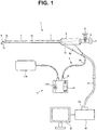
- an endoscope 1 of the present embodiment includes an insertion portion 2, an observation portion 3, an electrodeposition portion 10, and a connection portion 4.
- the endoscope 1 of the present embodiment includes a rod-like insertion portion 2 that can be inserted into a urethra of a human body that is a subject and includes, on a distal end portion 2a of the insertion portion 2, an observation portion 3 configured to observe inside of the subject.
- the endoscope 1 is not limited to a mode in which the insertion portion 2 is inserted into the urethra, and the endoscope 1 may be in a mode in which the insertion portion 2 is inserted into a trachea, a digestive tract, or other body cavities and tissues.
- the endoscope 1 is a so-called rigid endoscope in which the insertion portion 2 has a predetermined stiffness in an example of the present embodiment
- the endoscope 1 may be a so-called flexible endoscope in which the insertion portion 2 has flexibility.
- a shape of the insertion portion 2 is not limited to a linear shape, and the insertion portion 2 may have a bent shape.
- a cross section shape of the insertion portion 2 is not limited to a substantially circular or substantially square shape, and the shape may be a flat elliptical or rectangular shape.
- a treatment instrument insertion channel 7 that is a tube-like member is located inside of the insertion portion 2 of the present embodiment, for example.
- One end of the treatment instrument insertion channel 7 is connected to an opening portion 2b provided on the distal end portion 2a of the insertion portion 2, and the other end of the treatment instrument insertion channel 7 is connected to a treatment instrument insertion port 6 and an irrigation water injection port 8 provided on a grasping portion 5 described later.
- the grasping portion 5 is connected to a proximal end portion of the insertion portion 2.
- the grasping portion 5 is a part grasped by a user of the endoscope 1.
- the connection portion 4, the treatment instrument insertion port 6, and the irrigation water injection port 8 are provided on the grasping portion 5.
- connection portion 4 is a part configured to electrically connect the electrodeposition portion 10 described later to a power source section 11. Details of the connection portion 4 and the power source section 10 will be described later.
- the treatment instrument insertion port 6 and the irrigation water injection port 8 are opening portions connected to the treatment instrument insertion channel 7 that is a conduit located on the insertion portion 2.
- a cock 9 can be operated to switch a state in which the treatment instrument insertion channel 7 and the treatment instrument insertion port 6 are connected and a state in which the treatment instrument insertion channel 7 and the irrigation water injection port 8 are connected.
- a treatment instrument such as a puncture needle, can be inserted into the treatment instrument insertion channel 7 from the treatment instrument insertion port 6 to cause the treatment instrument to protrude from the opening portion 2b provided on the distal end portion 2a of the insertion portion 2.
- the irrigation water injection port 8 is a part configured to send a fluid into the subject through the treatment instrument insertion channel 7.
- the observation portion 3 is a part configured to observe inside of the subject based on at least one of an optical image and an ultrasound image.
- the observation portion 3 of the present embodiment includes, for example, a plurality of ultrasound transducers, and the part serves as an ultrasound transmission and reception portion configured to perform a scan with an ultrasound beam.
- the observation portion 3 is electrically connected to an observation apparatus 40 through an observation cable 12 passed through the insertion portion 2. More specifically, the observation cable 12 extends from the grasping portion 5 and is connected to the observation apparatus 40 through a connector portion 12a.
- the observation apparatus 40 connected through the observation cable 12 controls operation of the observation portion 3.
- the observation apparatus 40 generates an ultrasound image from a signal obtained by driving the observation portion 3 and displays the ultrasound image on an image display apparatus 41.
- the form of the observation portion 3 included in the endoscope 1 is not limited to the present embodiment.
- the observation portion 3 may be in a form of an electronic camera including an objective lens and an image pickup device.
- the observation portion 3 is electrically connected to the observation apparatus 40 through the observation cable 12, and the observation apparatus 40 generates an optical image obtained by driving the observation portion 3 and displays the optical image on the image display apparatus 41.
- an illumination section configured to emit illuminating light is located on the distal end portion 2a of the insertion portion 2.
- the observation portion 3 may include, for example, both of the ultrasound transmission and reception portion and the electronic camera, and the observation apparatus 40 may be configured to display the ultrasound image and the optical image on the image display apparatus 41.
- the observation portion 3 When the observation portion 3 is configured to observe inside of the subject based on the optical image, the observation portion 3 may include an objective lens and may be configured to transfer the optical image to an eyepiece located on the proximal end side of the insertion portion 2 through an optical fiber passed through the observation cable 12, for example.
- the electrodeposition portion 10 is a part provided on the insertion portion 2 and configured to store an electric charge or take an electric charge to electrodeposit an electrically charged substance.
- the electrodeposition portion 10 is configured to store an electric charge to electrodeposit an electrically charged substance on a surface of the insertion portion 2, for example.
- the electrodeposition portion 10 of the present embodiment is a member made of a conductive material exposed and provided around the insertion portion 2.
- the material forming the electrodeposition portion 10 is not particularly limited as long as the material is conductive, and for example, the material is a metal or a conductive resin.
- the electrodeposition portion 10 is, for example, a metallic cylindrical member in the present embodiment.
- the electrodeposition portion 10 is exposed substantially across the entire outer surface of the insertion portion 2. More specifically, of the outer surface of the insertion portion 2, the electrodeposition portion 10 is provided in a region excluding regions in which the observation portion 3 and the opening portion 2b are located.
- the electrodeposition portion 10 also functions as a structural member for the insertion portion 2 to have a predetermined stiffness, for example.
- a proximal end portion of the electrodeposition portion 10 is fixed to the grasping portion 5 through an insulating member 5a made of an electrically insulating material as shown in Fig. 2 . Therefore, the electrodeposition portion 10 and the grasping portion 5 are electrically insulated.
- the electrodeposition portion 10 may be exposed outward at a part of the outer surface of the insertion portion 2. That is, the outer surface of the insertion portion 2 may be formed by the electrodeposition portion 3 made of a conductive material and a member made of an electrically insulating material.
- the electrodeposition portion 10 is electrically connected to the power source section 11 through the connection portion 4. More specifically, the connection portion 4 of the present embodiment includes a conductive cable 4a with a distal end portion connected to the electrodeposition portion 10. The distal end portion of the conductive cable 4a is connected to an inner circumferential surface of the cylindrical electrodeposition portion 10 through soldering or the like. The conductive cable 4a extends outside of the endoscope 1 from the grasping portion 5.
- a connector portion 4b electrically connected to the power source section 11 described later is provided on a proximal end portion of the conductive cable 4a.
- the connector portion 4b may be directly connected to the power source section 11 or may be indirectly connected to the power source section 11 through another cable.
- the conductive cable 4a may be located only inside without extending outside of the endoscope 1, and the connector portion 4b may be provided on the outer surface of the grasping portion 5.
- the conductive cable 4a extends from the grasping portion 5 at a same place as the observation cable 12 in the present embodiment as shown in Fig. 1 , the conductive cable 4a and the observation cable 12 may extend from different places of the grasping portion 5.
- An inner surface of the cylindrical electrodeposition portion 10 is covered by an insulating film 10a made of an electrically insulating material.
- the insulating film 10a electrically insulates the members located in the insertion portion 2, such as the observation cable 4a and the treatment instrument insertion channel 7, and the electrodeposition portion 10.
- the power source section 11 is an apparatus configured to apply a voltage to the electrodeposition portion 10 or cause the electrodeposition portion 10 to take an electric charge.
- the power source section 11 is a direct current power source configured to apply a voltage to the electrodeposition portion 10.
- the power source section 11 is a static electricity generation apparatus configured to cause the electrodeposition portion 10 to take an electric charge.
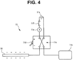
- the electrodeposition portion 10 is configured to store an electric charge to electrodeposit an electrically charged substance on the surface of the insertion portion 2 as described above. Therefore, as shown in Fig. 3 , the power source section 11 of the present embodiment includes a direct current power source section 11a configured to apply a voltage to the electrodeposition portion 10. The power source section 11 also includes a counter electrode plate 11b electrically connected to the direct current power source section 11a.
- the counter electrode plate 11b is made of a conductive member and is electrically connected to the direct current power source section 11a through a conductive cable.
- the counter electrode plate 11b can be attached to a body surface of the subject.
- the direct current power source section 11a is electrically connected to the electrodeposition portion 10 through the conductive cable 4a.
- the direct current power source section 11a applies a voltage between the electrodeposition portion 10 and the counter electrode plate 11b.
- the power source section 11 also includes: an operation switch 11f for the user to perform operation of starting and stopping the operation of the power source section 11; a polarity inversion portion 11c configured to switch a polarity of the voltage applied to the electrodeposition portion 10; a changeover switch 11d for the user to operate the polarity inversion portion 11c; and a restriction portion 11d configured to restrict an electric current outputted from the direct current power source section 11 a.
- the polarity inversion portion 11c switches the polarity of the voltage applied to the electrodeposition portion 10 according to the operation of the changeover switch 11d by the user.
- the electrodeposition portion 10 is electrically connected to a positive pole of the direct current power source section 11a
- the counter electrode plate 11b is electrically connected to a negative pole of the direct current power source section 11a.
- the polarity inversion portion 11c is activated by operating the changeover switch 11d from the state of Fig. 3 .
- the electrodeposition portion 10 is electrically connected to the negative pole of the direct current power source section 11a
- the counter electrode plate 11b is electrically connected to the positive pole of the direct current power source section 11a.
- the electrodeposition portion 10 stores a positive electric charge based on the operation of the power source section 11.
- the electrodeposition portion 10 stores a negative electric charge based on the operation of the power source section 11. In this way, the user can operate the changeover switch 11d to switch the polarity of the electric charge stored in the electrodeposition portion 10.
- the restriction portion 11e detects an electric current value outputted from the direct current power source section 11a and cuts off the electric circuit when the electric current value exceeds a predetermined value.
- the restriction portion 11e is an apparatus configured to prevent an electric current with equal to or greater than a predetermined value from flowing in the subject that comes in contact with the insertion portion 2 and the counter electrode plate 11b.
- a gel lubricant is applied around the insertion portion 2 before the insertion portion 2 of the endoscope 1 is inserted into the urethra of the subject.
- the type of the lubricant is not particularly limited, examples of the gel lubricant for medical equipment include lubricants containing Lidocaine or other anesthetics, such as Xylocaine Jelly, and lubricants not containing anesthetics, such as K-Y Jelly, Through Projelly, Endolubri (registered trademark), and CaineZero Jelly.
- the counter electrode plate 11b is attached to the body surface of the subject, such as belly, and the insertion portion 2 is inserted into the urethra.
- the operation switch 11f is turned on to start the operation of the power source section 11.
- the voltage is applied to the electrodeposition portion 10 provided on the insertion portion 2, and the electric charge is stored in the electrodeposition portion 10.
- Colloidal particles contained in the gel lubricant are generally electrically charged, and the colloidal particles contained in the lubricant applied to the surface of the insertion portion 2 are attracted by the electrodeposition portion 10.
- the voltage is applied to the electrodeposition portion 10, and the lubricant containing the colloidal particles that are electrically charged substances is electrodeposited on the electrodeposition portion 10 in the present embodiment. Therefore, detachment of the lubricant from the surface of the insertion portion 2 can be prevented even when the insertion portion 2 is moved in the subject, such as in the urethra.
- the changeover switch 11d can be operated in the present embodiment to switch the polarity of the electric charge stored in the electrodeposition portion 10 to thereby electrodeposit the lubricant on the electrodeposition portion 10 regardless of the polarity of the charge of the colloidal particles.
- an electrodeposition portion 20 and a power source section 21 are different from the first embodiment.
- the electrodeposition portion 20 provided on the insertion portion 2 of the endoscope 1 of the present embodiment is configured to take an electric charge to electrodeposit an electrically charged substance on the surface of the insertion portion 2, for example.
- the electrodeposition portion 20 is located on an outer circumferential portion of the insertion portion 2.
- the electrodeposition portion 20 of the present embodiment includes a conductive portion 20a and an insulating portion 20b.
- the conductive portion 20a is a member made of a conductive material, such as a metal and a conductive resin, and located near the outer circumference of the insertion portion 2.
- the conductive portion 20a is, for example, a metallic cylindrical member.
- the conductive portion 20a also functions as a structural member for the insertion portion 2 to have a predetermined stiffness, for example.
- a proximal end portion of the conductive portion 20a is fixed to the grasping portion 5 through the insulating member 5a made of an electrically insulating material. Therefore, the conductive portion 20a and the grasping portion 5 are electrically insulated.
- connection portion 4 of the present embodiment includes the conductive cable 4a with the distal end portion connected to the conductive portion 20a.
- the distal end portion of the conductive cable 4a is connected to an inner circumferential surface of the cylindrical conductive portion 20a through soldering or the like.
- the conductive cable 4a extends outside of the endoscope 1 from the grasping portion 5.
- the inner surface of the cylindrical conductive portion 20a is covered by the insulating film 10a made of an electrically insulating material.
- the insulating film 10a electrically insulates the members located in the insertion portion 2, such as the observation cable 4a and the treatment instrument insertion channel 7, and the conductive portion 20a.
- the insulating portion 20a is a member made of an electrically insulating material, such as a resin, and exposed to the surface of the insertion portion 2.
- the insulating portion 20a covers an outer surface of the conductive portion 20b and electrically insulates the conductive portion 20a and the outside of the endoscope 1.
- the power source section 21 of the present embodiment is an apparatus configured to cause the electrodeposition portion 20 to take an electric charge and includes a static electricity generation apparatus 21 a as shown in Fig. 7 .
- the power source section 21 also includes: an operation switch 21d for the user to perform operation of starting and stopping the operation of the power source section 21; a polarity inversion portion 21b configured to switch the polarity of the charge of the electrodeposition portion 20; and a changeover switch 21c for the user to cause the polarity inversion portion 21b to operate.
- the electrodeposition portion 20 electrically connected to the power source section 21 takes an electric charge based on the operation of the power source section 21.
- the user can operate the changeover switch 21c to switch the polarity of the charge of the electrodeposition portion 20.
- a gel lubricant is applied around the insertion portion 2 before the insertion portion 2 of the endoscope 1 is inserted into the urethra of the subject.
- the type of the lubricant is not particularly limited, examples of the gel lubricant for medical equipment include lubricants containing Lidocaine or other anesthetics, such as Xylocaine Jelly, and lubricants not containing anesthetics, such as K-Y Jelly, Through Projelly, Endolubri (registered trademark), and CaineZero Jelly.
- the operation switch 21 d is operated to start the operation of the power source section 21.
- the electrodeposition portion 20 provided on the insertion portion 2 takes an electric charge, and colloidal particles contained in the lubricant applied to the surface of the insertion portion 2 are attracted by the electrodeposition portion 20.
- the electrodeposition portion 20 is caused to take an electric charge, and the lubricant containing the colloidal particles that are electrically charged substances is electrodeposited on the electrodeposition portion 20 in the present embodiment. Therefore, detachment of the lubricant from the surface of the insertion portion 2 can be prevented even when the insertion portion 2 is moved in the subject, such as in the urethra.
- the changeover switch 21 c can be operated in the present embodiment to switch the polarity of the electrical strength of the electrodeposition portion 20 to thereby electrodeposit the lubricant on the electrodeposition portion 20 regardless of the polarity of the charge of the colloidal particles.
- the conductive portion 20a of the electrodeposition portion 20 is cylindrical and is arranged without a gap throughout the entire axial direction and circumferential direction of the insertion portion 2 in the present embodiment, the shape of the conductive portion 20a is not limited to the present embodiment.
- the conductive portion 20a may have a coil shape in which a linear member made of a conductive material is wound around a center axis of the insertion portion 2.
- the cylindrical insulating portion 20b is a structural member for the insertion portion 2 to have a predetermined stiffness, and the conductive portion 20a is wound around along an inner circumferential surface of the insulating portion 20b.
- the electrodeposition portion 20 can also be caused to take an electric charge in the present modification, and the lubricant containing the colloidal particles can be electrodeposited on the electrodeposition portion 20 as in the embodiment described above.
- the conductive portion 20a can have a coil shape as in the present modification to make the electrodeposition portion 20 flexible. Therefore, the electrodeposition portion 20 can be easily applied to an endoscope with a flexible insertion portion.
- the electrodeposition portion 20 is not limited to the coil shape as shown in the figure, and the electrodeposition portion 20 may be formed by a linear member made of a conductive material arranged in a mesh.
- the present invention is applied to the endoscope in the examples illustrated in the first and second embodiments, the present invention can be applied not only to the endoscope, but also to a treatment instrument that can be inserted into the subject.
- the present embodiment is an example in which the present invention is applied to a urethral catheter that is an example of the treatment instrument.
- the treatment instrument according to the present invention is not limited to the urethral catheter, and the treatment instrument can be equipment noninvasively inserted from an anatomical opening of a human body, such as mouth, flower, ears, anus, vagina, and urethra.
- the treatment instrument can be a tracheal suction catheter or the like inserted in-vivo from the mouth.
- a treatment instrument 30 of the present embodiment shown in Fig. 9 includes a rod-like insertion portion 31 that can be inserted into the urethra of a human body that is the subject.
- a balloon conduit 33 and a urinary conduit 34 are formed in the insertion portion 31.
- the balloon conduit 34 is linked to inside of a balloon 32 provided on a distal end portion 31a of the insertion portion 31, and a fluid for inflating the balloon 32 in the subject can be sent into the balloon 32.
- the urinary conduit 34 is a conduit connected to a urinary hole 31c provided on the distal end portion 31a of the insertion portion 31 and configured to discharge urine in the bladder.
- the other end of the urinary conduit 34 is connected to a bag or the like not shown that retains the urine.
- the electrodeposition portion 20 is located on an outer circumferential portion of the insertion portion 31.
- the electrodeposition portion 20 includes the conductive portion 20a and the insulating portion 20b.
- the conductive portion 20a is a member made of a conductive material, such as a metal and a conductive resin, and located near the outer circumference of the insertion portion 2.
- the conductive portion 20a is, for example, in a coil shape formed by winding a metallic wire.
- the conductive portion 20a may be a conductive linear member arranged in a mesh. Forming the conductive portion 20a in a coil shape or a mesh shape can prevent the existence of the conductive portion 20a from obstructing curving of the insertion portion 31.
- connection portion 4 of the present embodiment includes the conductive cable 4a with the distal end portion connected to the conductive portion 20a.
- the distal end portion of the conductive cable 4a is connected to the conductive portion 20a through soldering or the like.
- the insulating portion 20a is a member made of an electrically insulating material, such as a resin, and exposed to the surface of the insertion portion 2.
- the insulating portion 20a covers the outer surface of the conductive portion 20b and electrically insulates the conductive portion 20a and the outside of the treatment instrument 30.
- a gel lubricant is applied around the insertion portion 31 before the insertion portion 31 of the treatment instrument 30 is inserted into the urethra of the subject.
- the type of the lubricant is not particularly limited, examples of the gel lubricant for medical equipment include lubricants containing Lidocaine or other anesthetics, such as Xylocaine Jelly, and lubricants not containing anesthetics, such as K-Y Jelly, Through Projelly, Endolubri (registered trademark), and CaineZero Jelly.
- the operation switch 21 d is operated to start the operation of the power source section 21.
- the electrodeposition portion 20 provided on the insertion portion 31 takes an electric charge, and colloidal particles contained in the lubricant applied to the surface of the insertion portion 31 are attracted by the electrodeposition portion 20.
- the electrodeposition portion 20 is caused to take an electric charge, and the lubricant containing the colloidal particles that are electrically charged substances is electrodeposited on the electrodeposition portion 20 in the present embodiment. Therefore, detachment of the lubricant from the surface of the insertion portion 31 can be prevented even when the insertion portion 31 is moved in the subject, such as in the urethra.
- the effect of the lubricant applied to the surface of the insertion portion 31 in the subject can be held for a longer time as in the second embodiment.
- the endoscope 1 of the present embodiment is different from the first or second embodiment in that a plurality of particle pockets 13 in a concave shape configured to hold electrically charged particulate substances are formed on the surface of the insertion portion 2.
- Each of the plurality of particle pockets 13 includes an opening with a breadth that allows the colloidal particle contained in the gel lubricant for medical equipment to enter, and the particle pocket 13 has a depth with which part of the colloidal particle protrudes from the opening in a state that the colloidal particle has entered inside. That is, when the opening shape of the particle pocket 13 is approximated by a circle, the depth of the particle pocket 13 is a value smaller than a diameter of the circle approximating the opening shape.
- the circle approximating the opening shape may be an inscribed circle of the opening shape or a circumscribed circle. The circle may have a diameter between diameters of the inscribed circle and the circumscribed circle.
- the size and the depth of the opening of the particle pocket 13 are determined according to a diameter of the colloidal particles contained in the lubricant and are not limited.
- the diameter of the colloidal particles is generally about 1 nm to 100 nm. Therefore, in an example of the present embodiment, the diameter of the particle pocket 13 is 150 nm or smaller, and the depth is 95 nm or smaller.
- the particle pockets 13 of the present embodiment are formed such that the individual openings and depths are not constant, and the values are random.
- the plurality of particle pockets 13 in individually different shapes can be formed by chemical processing, such as etching, or mechanical processing, such as shot blasting.
- the shapes of the individual particle pockets 13 are different, and the particle pockets 13 can hold colloidal particles in various sizes. Note that the shapes of the plurality of particle pockets 13 may be substantially uniform.
- the plurality of particle pockets 13 are formed on the surface of the insertion portion 2 of the endoscope 1 on which the electrodeposition portion 10 or 20 is located in the present embodiment.
- the plurality of particle pockets 13 have shapes that allow holding the colloidal particles contained in the gel lubricant for medical equipment. Therefore, when the lubricant is applied to the surface of the insertion portion 2, and colloidal particles of the lubricant are electrodeposited on the electrodeposition portion 10 or 20, the colloidal particles enter the particle pockets 13 and are held by the particle pockets 13.
- the opening shapes of the particle pockets 13 can be approximated by circles in the description of the present embodiment, the shapes of the particle pockets 13 are not limited to these.
- the particle pockets 13 may be grooves carved in a belt shape in the circumferential direction of the outer circumferential surface of the insertion portion 2.
- the particle pockets 13 have a groove shape in which the width is 150 nm or smaller, and the depth is 95 nm or smaller.
- the endoscope 1 of the present embodiment is different from the first or second embodiment in that a plurality of concave portions 15 configured to hold the lubricant for medical tool are formed on the surface of the insertion portion 2.
- the plurality of concave portions 15 are V-shaped or U-shaped grooves carved in a belt shape in the circumferential direction on the outer circumferential surface of the insertion portion 2.
- the concave portions 15 that are belt-like grooves are arranged in the axial direction at predetermined intervals. Corner portions of places of valleys that are bottom portions of the concave portions 15 and places of mountains formed between adjacent concave portions 15 may be formed in a V-shape as shown in Fig. 11 or may have a shape rounded in a U-shape.
- the insertion portion 2 When the insertion portion 2 is inserted into the subject after applying the lubricant to the insertion portion 2 of the endoscope 1 of the present embodiment, the area that the tissue of the subject comes in contact with the surface of the insertion portion 2 becomes small because the concave portions 15 are formed on the surface of the insertion portion 2, and the frictional resistance between the tissue and the insertion portion 2 decreases. Furthermore, the lubricant is held in spaces in the concave portions 15, and the lubricant is supplied between the tissue of the subject and the surface of the insertion portion 2 from the inside of the concave portions 15 when the insertion portion 2 is moved in the subject. Therefore, the effect of the lubricant can be held for a longer time.
- the electrodeposition portion 10 or 20 is provided on the insertion portion 2, and the colloidal particles of the lubricant are electrodeposited on the surface of the insertion portion 2. Therefore, detachment of the lubricant from the surface of the insertion portion 2 can be further prevented.
- the effect of the lubricant applied to the surface of the insertion portion 2 can be held for a longer time in the subject in the endoscope 1 of the present embodiment.
- the plurality of particle pockets 13 configured to hold the colloidal particles of the lubricant described in the fourth embodiment may be formed on the surface of the insertion portion 2.
- the colloidal particles of the lubricant can be held in the particle pockets 13 by providing the particle pockets 13. Therefore, detachment of the lubricant from the surface of the insertion portion 2 can be further prevented, and the frictional resistance between the tissue and the insertion portion 2 can be reduced.
- the shape of the concave portions 15 is not limited to the belt-like grooves carved in the circumferential direction of the insertion portion 2 as shown in Fig. 11 .
- the concave portions 15 may be a plurality of grooves carved in two intersecting directions as in a first modification shown in Fig. 12 .
- the concave portions 15 may be, for example, hole-shaped in which outlines of the openings are closed as in a second modification shown in Fig. 13 .
- the arrangement of the concave portions 15 may be regular or may be random.
- the opening shape of the concave portions 15 is not particularly limited, and other than the illustrated circular shape, the shape may be polygonal or elliptical.
- the plurality of particle pockets 13 in the concave shapes configured to hold electrically charged particulate substances are formed on the surface of the insertion portion 31 of the treatment instrument 30 described in the third embodiment.
- the shapes of the particle pockets 13 are the same as the particle pockets 13 provided on the endoscope 1 in the fourth embodiment, and the same drawings as in the fourth embodiment will be used in the description.
- Each of the plurality of particle pockets 13 includes an opening with a breadth that allows the colloidal particle contained in the gel lubricant for medical equipment to enter, and the particle pocket 13 has a depth with which part of the colloidal particle protrudes from the opening in the state that the colloidal particle has entered inside. That is, when the opening shape of the particle pocket 13 is approximated by a circle, the depth of the particle pocket 13 is a value smaller than the diameter of the circle approximating the opening shape.
- the circle approximating the opening shape may be an inscribed circle of the opening shape or a circumscribed circle. The circle may have a diameter between the diameters of the inscribed circle and the circumscribed circle.
- the size and the depth of the opening of the particle pocket 13 are determined according to the diameter of the colloidal particles contained in the lubricant and are not limited.
- the diameter of the colloidal particles is generally about 1 nm to 100 nm. Therefore, in an example of the present embodiment, the diameter of the particle pocket 13 is 150 nm or smaller, and the depth is 95 nm or smaller.
- the particle pockets 13 are formed such that the individual openings and depths are not constant, and the values are random.
- the plurality of particle pockets 13 in individually different shapes can be formed by chemical processing, such as etching, or mechanical processing, such as shot blasting.
- the shapes of the individual particle pockets 13 are different, and the particle pockets 13 can hold colloidal particles in various sizes. Note that the shapes of the plurality of particle pockets 13 may be substantially uniform.
- the plurality of particle pockets 13 are formed on the surface of the insertion portion 31 of the treatment instrument 30 on which the electrodeposition portion 20 is located in the present embodiment.
- the plurality of particle pockets 13 have shapes that allow holding the colloidal particles contained in the gel lubricant for medical equipment. Therefore, when the lubricant is applied to the surface of the insertion portion 31, and colloidal particles of the lubricant are electrodeposited on the electrodeposition portion 10 or 20, the colloidal particles enter the particle pockets 13 and are held by the particle pockets 13.
- the opening shapes of the particle pockets 13 can be approximated by circles in the description of the present embodiment, the shapes of the particle pockets 13 are not limited to these.
- the particle pockets 13 may be grooves carved in a belt shape in the circumferential direction of the outer circumferential surface of the insertion portion 31.
- the particle pockets 13 have a groove shape in which the width is 150 nm or smaller, and the depth is 95 nm or smaller.
- the plurality of concave portions 15 configured to hold the lubricant for medical tool are formed on the surface of the insertion portion 31 of the treatment instrument 30 described in the third or sixth embodiment.
- the shape of the concave portions 15 is the same as the concave portions 15 provided on the endoscope 1 in the fifth embodiment, and the same drawings as in the fifth embodiment will be used in the description.
- the plurality of concave portions 15 are V-shaped or U-shaped grooves carved in a belt shape in the circumferential direction on the outer circumferential surface of the insertion portion 2.
- the concave portions 15 that are belt-like grooves are arranged in the axial direction at predetermined intervals. Corner portions of places of valleys that are bottom portions of the concave portions 15 and places of mountains formed between adjacent concave portions 15 may be formed in a V-shape as shown in Fig. 11 or may have a shape rounded in a U-shape.
- the insertion portion 31 When the insertion portion 31 is inserted into the subject after applying the lubricant to the insertion portion 31 of the treatment instrument 30 of the present embodiment, the area that the tissue of the subject comes in contact with the surface of the insertion portion 31 becomes small because the concave portions 15 are formed on the surface of the insertion portion 31, and the frictional resistance between the tissue and the insertion portion 31 decreases. Furthermore, the lubricant is held in spaces in the concave portions 15, and the lubricant is supplied between the tissue of the subject and the surface of the insertion portion 31 from the inside of the concave portions 15 when the insertion portion 31 is moved in the subject. Therefore, the effect of the lubricant can be held for a longer time.
- the electrodeposition portion 20 is provided on the insertion portion 31, and the colloidal particles of the lubricant are electrodeposited on the surface of the insertion portion 31. Therefore, detachment of the lubricant from the surface of the insertion portion 31 can be further prevented.
- the effect of the lubricant applied to the surface of the insertion portion 31 can be held for a longer time in the subject in the treatment instrument 30 of the present embodiment.
- the plurality of particle pockets 13 configured to hold the colloidal particles of the lubricant described in the sixth embodiment may be formed on the surface of the insertion portion 31.
- the colloidal particles of the lubricant can be held in the particle pockets 13 by providing the particle pockets 13. Therefore, detachment of the lubricant from the surface of the insertion portion 31 can be further prevented, and the frictional resistance between the tissue and the insertion portion 31 can be reduced.
- the shape of the concave portions 15 is not limited to the belt-like grooves carved in the circumferential direction of the insertion portion 2 as shown in Fig. 11 .
- the concave portions 15 may be a plurality of grooves carved in two intersecting directions as in a first modification shown in Fig. 12 .
- the concave portions 15 may be, for example, hole-shaped in which outlines of the openings are closed as in a second modification shown in Fig. 13 .
- the arrangement of the concave portions 15 may be regular or may be random.
- the opening shape of the concave portions 15 is not particularly limited, and other than the illustrated circular shape, the shape may be polygonal or elliptical.
Landscapes
- Health & Medical Sciences (AREA)
- Life Sciences & Earth Sciences (AREA)
- Physics & Mathematics (AREA)
- Surgery (AREA)
- Optics & Photonics (AREA)
- Engineering & Computer Science (AREA)
- Medical Informatics (AREA)
- Public Health (AREA)
- Biophysics (AREA)
- Nuclear Medicine, Radiotherapy & Molecular Imaging (AREA)
- Pathology (AREA)
- Radiology & Medical Imaging (AREA)
- Veterinary Medicine (AREA)
- Biomedical Technology (AREA)
- Heart & Thoracic Surgery (AREA)
- General Health & Medical Sciences (AREA)
- Molecular Biology (AREA)
- Animal Behavior & Ethology (AREA)
- Astronomy & Astrophysics (AREA)
- General Physics & Mathematics (AREA)
- Manufacturing & Machinery (AREA)
- Endoscopes (AREA)
- Instruments For Viewing The Inside Of Hollow Bodies (AREA)
Applications Claiming Priority (2)
| Application Number | Priority Date | Filing Date | Title |
|---|---|---|---|
| JP2014084808 | 2014-04-16 | ||
| PCT/JP2015/061019 WO2015159779A1 (ja) | 2014-04-16 | 2015-04-08 | 内視鏡及び処置具 |
Publications (2)
| Publication Number | Publication Date |
|---|---|
| EP3132736A1 true EP3132736A1 (de) | 2017-02-22 |
| EP3132736A4 EP3132736A4 (de) | 2017-12-13 |
Family
ID=54323990
Family Applications (1)
| Application Number | Title | Priority Date | Filing Date |
|---|---|---|---|
| EP15780738.9A Withdrawn EP3132736A4 (de) | 2014-04-16 | 2015-04-08 | Endoskop und instrument |
Country Status (5)
| Country | Link |
|---|---|
| US (2) | US10154774B2 (de) |
| EP (1) | EP3132736A4 (de) |
| JP (1) | JP6006432B2 (de) |
| CN (1) | CN106163368B (de) |
| WO (1) | WO2015159779A1 (de) |
Families Citing this family (3)
| Publication number | Priority date | Publication date | Assignee | Title |
|---|---|---|---|---|
| US11707602B2 (en) * | 2019-08-29 | 2023-07-25 | Leonid Shendelman | Catheter system |
| JP2024054583A (ja) * | 2022-10-05 | 2024-04-17 | 富士フイルム株式会社 | 内視鏡システム及びその作動方法 |
| CN115813758A (zh) * | 2022-11-11 | 2023-03-21 | 王建安 | 静电针刺麻醉装置 |
Family Cites Families (22)
| Publication number | Priority date | Publication date | Assignee | Title |
|---|---|---|---|---|
| WO1981003271A1 (en) * | 1980-05-13 | 1981-11-26 | American Hospital Supply Corp | A multipolar electrosurgical device |
| US4855077A (en) * | 1988-04-20 | 1989-08-08 | Takiron Co., Ltd. | Sticking agent of ionic-conductive polymer |
| JP3142949B2 (ja) * | 1992-05-01 | 2001-03-07 | オリンパス光学工業株式会社 | 内視鏡 |
| JP3597216B2 (ja) * | 1994-06-22 | 2004-12-02 | オリンパス株式会社 | カバー式内視鏡 |
| US5630426A (en) * | 1995-03-03 | 1997-05-20 | Neovision Corporation | Apparatus and method for characterization and treatment of tumors |
| JP3469770B2 (ja) | 1998-03-05 | 2003-11-25 | オリンパス光学工業株式会社 | 内視鏡用親水性潤滑剤 |
| JP3641381B2 (ja) * | 1999-03-10 | 2005-04-20 | テルモ株式会社 | 医療用チューブ及びその製造方法 |
| JP2002051967A (ja) * | 2000-08-11 | 2002-02-19 | Fuji Photo Optical Co Ltd | 内視鏡 |
| CA2426045A1 (en) * | 2000-10-24 | 2002-05-02 | Bausch & Lomb Incorporated | Prevention of bacterial attachment to biomaterials by cationic polysaccharides |
| JP2004057324A (ja) * | 2002-07-26 | 2004-02-26 | Pentax Corp | 内視鏡または内視鏡処置具の殺菌方法 |
| US7767219B2 (en) * | 2003-01-31 | 2010-08-03 | Boston Scientific Scimed, Inc. | Localized drug delivery using drug-loaded nanocapsules |
| US20070005024A1 (en) * | 2005-06-10 | 2007-01-04 | Jan Weber | Medical devices having superhydrophobic surfaces, superhydrophilic surfaces, or both |
| KR20080056200A (ko) | 2005-09-16 | 2008-06-20 | 티티아이 엘뷰 가부시키가이샤 | 카테터형 이온토포레시스 장치 |
| JP5330257B2 (ja) | 2007-10-29 | 2013-10-30 | オリンパスメディカルシステムズ株式会社 | 医療機器 |
| US20090297581A1 (en) * | 2008-05-28 | 2009-12-03 | Boston Scientific Scimed, Inc. | Medical devices having electrodeposited coatings |
| WO2010019645A2 (en) * | 2008-08-14 | 2010-02-18 | Boston Scientific Scimed, Inc. | Medical devices having electrodeposited conductive polymer coatings |
| US20120253130A1 (en) * | 2009-12-22 | 2012-10-04 | Osamu Motoyama | Endoscope having extra-fine diameter |
| JP2011177381A (ja) * | 2010-03-02 | 2011-09-15 | Terumo Corp | 医療用具システム |
| US8992949B1 (en) * | 2011-11-17 | 2015-03-31 | Unicare Biomedical, Inc. | Biocompatible polymeric compositions having microcrystalline and amorphous components and methods for their manufacture |
| JP2014054314A (ja) * | 2012-09-11 | 2014-03-27 | Olympus Corp | 生体情報取得装置 |
| CN105358036B (zh) * | 2013-06-28 | 2017-09-19 | 奥林巴斯株式会社 | 内窥镜系统 |
| WO2015085011A1 (en) * | 2013-12-04 | 2015-06-11 | Obalon Therapeutics , Inc. | Systems and methods for locating and/or characterizing intragastric devices |
-
2015
- 2015-04-08 CN CN201580018780.5A patent/CN106163368B/zh not_active Expired - Fee Related
- 2015-04-08 EP EP15780738.9A patent/EP3132736A4/de not_active Withdrawn
- 2015-04-08 JP JP2015545591A patent/JP6006432B2/ja active Active
- 2015-04-08 WO PCT/JP2015/061019 patent/WO2015159779A1/ja not_active Ceased
-
2016
- 2016-10-06 US US15/286,802 patent/US10154774B2/en active Active
-
2018
- 2018-12-06 US US16/211,855 patent/US10881270B2/en active Active
Also Published As
| Publication number | Publication date |
|---|---|
| WO2015159779A1 (ja) | 2015-10-22 |
| US10154774B2 (en) | 2018-12-18 |
| JPWO2015159779A1 (ja) | 2017-04-13 |
| US20190104925A1 (en) | 2019-04-11 |
| CN106163368B (zh) | 2018-02-27 |
| EP3132736A4 (de) | 2017-12-13 |
| CN106163368A (zh) | 2016-11-23 |
| US10881270B2 (en) | 2021-01-05 |
| JP6006432B2 (ja) | 2016-10-12 |
| US20170020369A1 (en) | 2017-01-26 |
Similar Documents
| Publication | Publication Date | Title |
|---|---|---|
| US8465419B2 (en) | Endoscope insertion unit, endoscope and endoscope system | |
| CN115348831B (zh) | 模块化内窥镜的系统和方法 | |
| US10881270B2 (en) | Endoscope and treatment instrument with lubricant electrodeposition | |
| US20090306470A1 (en) | Medical apparatus | |
| US20110160752A1 (en) | Elongate magnet for a magnetic anastomosis device | |
| US20050272976A1 (en) | Endoscope insertion aiding device | |
| US20040176664A1 (en) | In-vivo extendable element device and system, and method of use | |
| EP2502553A1 (de) | Drahtführungen und Verankerungen für Endoskopie | |
| CN1219855A (zh) | 内窥镜的改进或与其相关的部件 | |
| EP1854421A3 (de) | Endoskopische transluminale chirurgische Systeme | |
| JP2009502215A (ja) | 体腔を照射し、観察し、モニタリングするための方法および装置 | |
| US9737197B2 (en) | Medical scope attachment device and system | |
| JP2006334246A (ja) | 内視鏡装置 | |
| Makishi et al. | Active bending electric endoscope using shape memory alloy coil actuators | |
| JP7129345B2 (ja) | エレクトロポレーション用の増設キャップ及びシステム | |
| US11779428B2 (en) | Disposable medical clamp light | |
| JP4642424B2 (ja) | 体内医療装置 | |
| KR101631883B1 (ko) | 내시경관절 구조 | |
| CN210019461U (zh) | 一种腹腔镜手术用的牵引装置 | |
| CN224179702U (zh) | 一种用于胶囊内镜的推送装置 | |
| CN219021088U (zh) | 一种内镜用保护套 | |
| CN210698209U (zh) | 入体式理疗训练装置及其尾部结构 | |
| CN116531082A (zh) | 一种内窥镜及其前端盖 | |
| CN121729189A (zh) | 用于机器人腔内缝合器械的系统和方法以及针驱动器 | |
| UA56850A (uk) | Пристрій для обстеження анатомічних порожнин пацієнта |
Legal Events
| Date | Code | Title | Description |
|---|---|---|---|
| STAA | Information on the status of an ep patent application or granted ep patent |
Free format text: STATUS: THE INTERNATIONAL PUBLICATION HAS BEEN MADE |
|
| PUAI | Public reference made under article 153(3) epc to a published international application that has entered the european phase |
Free format text: ORIGINAL CODE: 0009012 |
|
| STAA | Information on the status of an ep patent application or granted ep patent |
Free format text: STATUS: REQUEST FOR EXAMINATION WAS MADE |
|
| 17P | Request for examination filed |
Effective date: 20161005 |
|
| AK | Designated contracting states |
Kind code of ref document: A1 Designated state(s): AL AT BE BG CH CY CZ DE DK EE ES FI FR GB GR HR HU IE IS IT LI LT LU LV MC MK MT NL NO PL PT RO RS SE SI SK SM TR |
|
| AX | Request for extension of the european patent |
Extension state: BA ME |
|
| DAV | Request for validation of the european patent (deleted) | ||
| DAX | Request for extension of the european patent (deleted) | ||
| A4 | Supplementary search report drawn up and despatched |
Effective date: 20171113 |
|
| RIC1 | Information provided on ipc code assigned before grant |
Ipc: G02B 23/24 20060101ALI20171107BHEP Ipc: A61B 1/00 20060101AFI20171107BHEP |
|
| STAA | Information on the status of an ep patent application or granted ep patent |
Free format text: STATUS: THE APPLICATION IS DEEMED TO BE WITHDRAWN |
|
| 18D | Application deemed to be withdrawn |
Effective date: 20201103 |