EP3132902A1 - Dispositif de coupe de materiaux solides - Google Patents
Dispositif de coupe de materiaux solides Download PDFInfo
- Publication number
- EP3132902A1 EP3132902A1 EP16182495.8A EP16182495A EP3132902A1 EP 3132902 A1 EP3132902 A1 EP 3132902A1 EP 16182495 A EP16182495 A EP 16182495A EP 3132902 A1 EP3132902 A1 EP 3132902A1
- Authority
- EP
- European Patent Office
- Prior art keywords
- helical
- angle
- cutting
- turns
- winding
- Prior art date
- Legal status (The legal status is an assumption and is not a legal conclusion. Google has not performed a legal analysis and makes no representation as to the accuracy of the status listed.)
- Withdrawn
Links
- 238000005520 cutting process Methods 0.000 title claims abstract description 54
- 239000011343 solid material Substances 0.000 title claims abstract description 8
- 239000000463 material Substances 0.000 claims description 71
- 238000004804 winding Methods 0.000 claims description 70
- 230000007704 transition Effects 0.000 claims description 2
- 238000003860 storage Methods 0.000 description 4
- 239000002023 wood Substances 0.000 description 3
- 241000237858 Gastropoda Species 0.000 description 2
- 230000000694 effects Effects 0.000 description 2
- 238000004519 manufacturing process Methods 0.000 description 2
- 238000010008 shearing Methods 0.000 description 2
- 125000006850 spacer group Chemical group 0.000 description 2
- 238000003466 welding Methods 0.000 description 2
- 238000002485 combustion reaction Methods 0.000 description 1
- 230000003247 decreasing effect Effects 0.000 description 1
- 230000001419 dependent effect Effects 0.000 description 1
- 238000010304 firing Methods 0.000 description 1
Images


Classifications
-
- B—PERFORMING OPERATIONS; TRANSPORTING
- B02—CRUSHING, PULVERISING, OR DISINTEGRATING; PREPARATORY TREATMENT OF GRAIN FOR MILLING
- B02C—CRUSHING, PULVERISING, OR DISINTEGRATING IN GENERAL; MILLING GRAIN
- B02C19/00—Other disintegrating devices or methods
- B02C19/22—Crushing mills with screw-shaped crushing means
-
- B—PERFORMING OPERATIONS; TRANSPORTING
- B27—WORKING OR PRESERVING WOOD OR SIMILAR MATERIAL; NAILING OR STAPLING MACHINES IN GENERAL
- B27L—REMOVING BARK OR VESTIGES OF BRANCHES; SPLITTING WOOD; MANUFACTURE OF VENEER, WOODEN STICKS, WOOD SHAVINGS, WOOD FIBRES OR WOOD POWDER
- B27L11/00—Manufacture of wood shavings, chips, powder, or the like; Tools therefor
Definitions
- the invention relates to a device for cutting solid materials according to the preamble of patent claim 1.
- slicers offer an additional technical solution for shredding solid materials (mainly logs and branches).
- Screw chippers are mainly used for the production of coarser clippings as a drum and disc chipper.
- screw chippers are made in two conical and cylindrical screw designs.
- conical worm design the material is fed axially below the worm shaft to the smaller diameter worm. Due to the rotation of the conical shape of the screw about the axis, the material is pressed against a radial counter-blade and a lateral support, pulled in and sheared off by the decreasing distance of the counter-blade to the screw. The material must slide under full pressure of the cutting force along the counter-blade and the support. A correspondingly high power requirement and a very high storage stability of the screw are necessary.
- the shredded material is transported axially through the rotating screw flight to the end of the screw where it is fed with various systems, e.g. Conveyor or throw blower applied. Since the shredded material is transported through the entire screw, it often comes in practice to block the winding.
- the material is fed laterally at a defined angle to the axis of rotation of the worm.
- the rotation of the screw the material is pressed against a laterally inclined counter blade and a support, fed and sheared.
- the material must slide under full pressure of the cutting force along the counter-blade and the support. A correspondingly high power requirement and a very high storage stability of the screw is needed.
- the comminuted material is transported by ejector in the screw winding radially out of the screw and discharged for example with a conveyor belt.
- a device for cutting solid materials comprising at least two spiral-shaped windings which are arranged such that they rotate about a common axis of rotation, are arranged counter to one another in their effective direction in such a way that a cutting movement takes place between the spiral-shaped windings.
- a counter blade which is fixed as in prior art systems and on which the material must slide along under full cutting force is therefore not required.
- the force required to cut the material is significantly lower.
- the helical windings are further arranged to each other such that the cutting force of each individual turn acts on the same axis of rotation and is received within the worm.
- the helical windings are further arranged such that an angle of the direction of action of the first helical winding to the direction of action of the second helical winding between 30 ° and 180 ° is that the effective directions against each other that a supplied material by the cutting movement is pulled into the device.
- the direction of action of the first helical winding is at an angle between -30 ° and + 60 ° to the axis of rotation
- the effective direction of the second helical winding at an angle between 30 ° and 160 ° to the axis of rotation, wherein the effective directions are opposite to each other.
- the opposite arrangement of the windings ensures that the material is gripped from both sides. As a result, the material is reliably drawn in and crushed by one another at an angle of the cutting surfaces of less than 180 °.
- the addition of a collection system, for example by means of rollers, belts or the like is not necessary.
- At least one breakthrough is arranged on at least one helical winding.
- At least one receptacle is arranged at a distance from at least one of the spiral-shaped windings. By this distance, the crushed material can be discharged from the screw.
- the device further comprises a support at a distance from at least one of the helical turns.
- This overlay can be arranged at a distance from the winding or turns such that the material to be shredded can be greater in thickness / diameter than the outer diameter of at least one turn.
- the unprocessed material in the case of one turn is then correspondingly comminuted by another turn. Smaller turns reduce the production costs of the turns and reduce the power requirement of the cutting process.
- a knife is arranged at least at one of the helical turns at the transition between the helical turns.
- the knife bridges the gap between the turns, which becomes larger, above all, by re-sharpening the turns. This reliably shears off the material.
- the angle between the cutting surfaces of the helical turns to each other between 90 ° and 200 °.
- the cut is more peeling, whereby the clippings receives a fan-like structure primarily in woody materials.
- the cut is more cutting, whereby the cut material has massive pieces.
- the angle between the free surfaces of the helical turns is between 90 ° and 180 °. With a larger angle of the open spaces to each other, the feed speed of the material increases and the Thomasgut publishede be larger.
- the novel device for cutting solid materials is based on at least two screw windings, each having a cutting geometry and are arranged in opposite directions to each other in their direction of action, that the material is fed independently and thereby crushed.
- FIGS. 1a to 1c show various possibilities, such as individual screw windings can be performed.
- the essential feature of a screw is that at least one flank is spirally wound about an axis X, the so-called winding. In this case, the flank winds per revolution about a pitch P along the effective direction W.
- the in FIG. 1 A screw shown a turn 1 with effective direction W perpendicular to the axis of rotation X.
- the in FIG. 1b shown snail shows a turn 2 with effective direction W along or parallel to the axis of rotation X. In between, any directions of action are possible.
- the Figure 1c shown snail shows, for example, a winding 3 with effective direction W of about 45 ° to the rotation axis X.
- the winding must have a cutting edge. This is achieved by the arrangement of the cutting surface 11 and free surface 12 at an angle a to each other.
- the angle a is usually between 20 ° and 90 °.
- the pitch P is constant, but it can also be variable in course.
- the effective direction W is usually linear, but can also be curved in course.
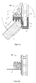
- FIG. 2a shows a possible embodiment of how two windings 10 and 20 can be arranged to each other.
- the angle g of the direction of action W1 of the first turn 10 to the rotation axis X is between -30 ° and + 30 °
- the angle i of the effective direction W2 of the second turn 20 to the rotation axis X between 60 ° and 150 °.
- the direction of action W1 of the winding 10 is parallel to the axis of rotation X and the direction of action W2 of the winding 20 is perpendicular to the axis of rotation X.
- the effective directions W1 and W2 run in opposite directions.
- the material 4 to be processed rests on a support 3 and is fed to the windings 10 and 20 at the pull-in angle c to the axis of rotation X.
- the direction of action W1 of the winding 10 at an angle f between 30 ° and 180 ° to the direction of action W2 of the winding 20 is detected by the rotation of the windings 10 and 20 about the rotation axis X, the material 4 on both sides of the windings 10 and 20, independently retracted and crushed.
- the comminution takes place completely between the two cutting turns 10 and 20.
- no counter cutting edge is necessary, on which the material 4 has to slide along full cutting pressure, only the support 3 must counteract the torque of the screw 100 comprising the turns 10 and 20.
- the cutting force required is significantly lower than with existing systems.
- the main cutting force within the screw 100 occurs and need not be absorbed by the bearing of the screw 100.
- the angle d of the cutting surfaces 11 of the respective turns 10 and 20 to each other influences the cutting behavior and thus the nature of the cut material and is preferably between 90 ° and 200 °. When cutting wood or materials of similar nature, the material is peeled at a smaller angle d more than cut and the cut gets a fan-like structure.
- the angle e is preferably between 90 ° and 180 °.
- the pitch P and the arrangement of the cutting surface 11 and free surface 12 to the respective direction of action W1 or W2 may be identical in both windings 10 and 20, but also different. This influences on the one hand the pull-in angle c of the material 4, on the other hand the resulting structure of the cut material.
- the screw 100 with several turns may consist of one part or of several parts joined together with, for example, one turn each.
- Some of the material shredded by the winding 10 falls radially out of the winding 10, in part it pushes the winding 10 axially through the winding 20.
- the material shredded by the winding 20 conveys the winding 20 to the winding 10.
- the winding 10 additionally pushes the material through the winding 20.
- at least one breakthrough 9 may be present in the turn 20, whereby the hitherto resulting cut material is removed by the cutting movement. This additionally prevents clogging of the winding 20.
- This opening 8 with an opening can be produced, for example, by screwing or welding the winding 20 and receptacle 6 by means of spacer bolts 5 or the like.
- a gap 7 between the windings 10 and 20, which possibly arises by re-sharpening the turns 10 and 20 or the cut surfaces 11 or 12, can be bridged with a knife (not shown) in order to ensure reliable shearing of the cut material.
- height h of the support 3 to the winding 10 may be zero or greater. If the height h is greater than zero, ie the support 3 lies below the winding 10, then the thickness or the diameter of the supplied material 4 can be greater than the outer diameter of the winding 10. A portion of the material 4 can pass above and below the winding 10 on the winding 10 over, but is then crushed by the winding 20.
- FIG. 3 shows a further embodiment of how two windings 30 and 40 can be arranged to each other.
- the angle g of the effective direction W1 of the first turn 30 to the axis of rotation X is between 30 ° and 60 °
- the angle i of the effective direction W2 of the second turn 40 to the axis of rotation X is between 30 ° and 60 °.
- the effective directions W1 and W2 run in opposite directions.
- the material 4 rests on a support 3 and is supplied to the turns 30 and 40 at an angle c to the axis of rotation X.
- the angle d of the cutting surfaces 11 of the respective turns 30 and 40 to each other influences the cutting behavior and thus the quality of the cut material and is preferably between 90 ° and 200 °.
- the material is peeled at a smaller angle d more than cut and the cut gets a fan-like structure.
- a larger angle d ie when the angle is in the direction of 180 ° and larger, the peeling effect is reduced and more massive pieces are cut.
- the material 4 is cut by the turns 30 and 40 from both sides simultaneously toward the center.
- the angle e is preferably between 90 ° and 180 °.
- the pitch P and the arrangement of the cutting surface 11 and free surface 12 to the respective effective direction W1 or W2 can be identical, but also different in both windings 30 and 40. This influences on the one hand the pull-in angle c of the material 4, on the other hand the resulting structure of the cut material.
- the screw 100 with several turns may consist of one part or of several parts joined together with, for example, one turn each.
- the material 4 shredded by the windings 30 and 40 partially falls radially out of the turns 30 and 40, in part pushing the turns 30 and 40 along their directions of action W1 and W2 to the end of the turns 30 and 40 and falling through them Rotation through the cavity or the gap L out of the screw 100 out.
- each individual turn 30 and 40 at least one opening 9 through the turns 30 and / or 40 may be present, whereby the hitherto produced cut material is removed by the cutting movement. This additionally prevents clogging of the turns 30 and / or 40.
- a distance 8 and radially to the outside at least one opening are necessary.
- This distance 8 with opening for example, by screwing or welding of the winding 30 and / or 40 and the associated receptacle 6 means Spacer 5 or the like can be generated.
- a gap 7 between the turns 30 and 40, which possibly arises by re-sharpening the turns 30 and 40 or the cut surfaces 11 or 12, can be bridged with a knife (not shown) in order to ensure reliable shearing of the cut material.
- FIGS. 2a and 3 shown arrangements of the windings 10 and 20 or 30 and 40 with respect to the axis of rotation are only examples and can over the in FIGS. 2a and 3 shown arrangements can be varied as desired. It is only important that the angles d and e lie in the above-described ranges.
Landscapes
- Engineering & Computer Science (AREA)
- Life Sciences & Earth Sciences (AREA)
- Food Science & Technology (AREA)
- Manufacturing & Machinery (AREA)
- Mechanical Engineering (AREA)
- Wood Science & Technology (AREA)
- Forests & Forestry (AREA)
- Disintegrating Or Milling (AREA)
Applications Claiming Priority (1)
| Application Number | Priority Date | Filing Date | Title |
|---|---|---|---|
| DE102015113645.7A DE102015113645B4 (de) | 2015-08-18 | 2015-08-18 | Vorrichtung zum Schneiden von festen Materialien |
Publications (1)
| Publication Number | Publication Date |
|---|---|
| EP3132902A1 true EP3132902A1 (fr) | 2017-02-22 |
Family
ID=56571187
Family Applications (1)
| Application Number | Title | Priority Date | Filing Date |
|---|---|---|---|
| EP16182495.8A Withdrawn EP3132902A1 (fr) | 2015-08-18 | 2016-08-03 | Dispositif de coupe de materiaux solides |
Country Status (2)
| Country | Link |
|---|---|
| EP (1) | EP3132902A1 (fr) |
| DE (1) | DE102015113645B4 (fr) |
Citations (8)
| Publication number | Priority date | Publication date | Assignee | Title |
|---|---|---|---|---|
| US3645308A (en) * | 1968-12-20 | 1972-02-29 | Philip Nilsson | Log-levelling machines |
| DE2400810A1 (de) * | 1974-01-09 | 1975-07-17 | Boehl Gmbh Maschf | Werkzeugtraeger fuer hackmesser |
| US4431039A (en) * | 1982-02-26 | 1984-02-14 | The United States Of America As Represented By The Secretary Of Agriculture | Involuted disc slicer |
| US4630658A (en) * | 1985-05-16 | 1986-12-23 | The United States Of America As Represented By The Secretary Of Agriculture | Counter rotating double disc chunker |
| WO2001049418A1 (fr) * | 1999-12-31 | 2001-07-12 | Giuseppe Loppoli | Machine de coupe-melange de dechets de bois |
| EP1172148A1 (fr) * | 2000-07-14 | 2002-01-16 | New Activation Technology (NAT) AG | Dispositif et procédé pour réduction de caoutchouc |
| EP1872921B1 (fr) | 2006-06-30 | 2010-01-27 | Laitilan Metalli Laine Oy | Spirale de broyage, procédé de production de copeaux et machine de broyage |
| DE202011004698U1 (de) | 2011-03-31 | 2012-08-23 | Wurster Oberflächenbearbeitung GmbH | Hacker mit zylindrischer Schnecke |
Family Cites Families (2)
| Publication number | Priority date | Publication date | Assignee | Title |
|---|---|---|---|---|
| DE19837436A1 (de) * | 1998-08-18 | 2000-02-24 | Franz Wieneke | Zerkleinerungseinrichtung für stengelige Pflanzen und Gehölze |
| SE530169C2 (sv) * | 2007-02-23 | 2008-03-18 | Soederhamn Eriksson Ab | Reducerskiva, planreduceringsmaskin innefattande en dylik reducerskiva, samt en huggdonssats för en dylik reducerskiva |
-
2015
- 2015-08-18 DE DE102015113645.7A patent/DE102015113645B4/de not_active Expired - Fee Related
-
2016
- 2016-08-03 EP EP16182495.8A patent/EP3132902A1/fr not_active Withdrawn
Patent Citations (8)
| Publication number | Priority date | Publication date | Assignee | Title |
|---|---|---|---|---|
| US3645308A (en) * | 1968-12-20 | 1972-02-29 | Philip Nilsson | Log-levelling machines |
| DE2400810A1 (de) * | 1974-01-09 | 1975-07-17 | Boehl Gmbh Maschf | Werkzeugtraeger fuer hackmesser |
| US4431039A (en) * | 1982-02-26 | 1984-02-14 | The United States Of America As Represented By The Secretary Of Agriculture | Involuted disc slicer |
| US4630658A (en) * | 1985-05-16 | 1986-12-23 | The United States Of America As Represented By The Secretary Of Agriculture | Counter rotating double disc chunker |
| WO2001049418A1 (fr) * | 1999-12-31 | 2001-07-12 | Giuseppe Loppoli | Machine de coupe-melange de dechets de bois |
| EP1172148A1 (fr) * | 2000-07-14 | 2002-01-16 | New Activation Technology (NAT) AG | Dispositif et procédé pour réduction de caoutchouc |
| EP1872921B1 (fr) | 2006-06-30 | 2010-01-27 | Laitilan Metalli Laine Oy | Spirale de broyage, procédé de production de copeaux et machine de broyage |
| DE202011004698U1 (de) | 2011-03-31 | 2012-08-23 | Wurster Oberflächenbearbeitung GmbH | Hacker mit zylindrischer Schnecke |
Also Published As
| Publication number | Publication date |
|---|---|
| DE102015113645B4 (de) | 2021-02-04 |
| DE102015113645A1 (de) | 2017-02-23 |
Similar Documents
| Publication | Publication Date | Title |
|---|---|---|
| DE1453328C3 (de) | Schneidmesser für eine mit umlaufenden Messerträger versehene Vorrichtung zur Herstellung von Holzschnitzeln | |
| EP0529221B1 (fr) | Dispositif de broyage | |
| EP2758588B1 (fr) | Désintégrateur pour brasser des vieux papiers et des matières cellulosiques | |
| EP0387868B1 (fr) | Dispositif de broyage pour déchets de bois | |
| DE4242740A1 (de) | Zerkleinerungsmaschine | |
| DE102015113645B4 (de) | Vorrichtung zum Schneiden von festen Materialien | |
| EP0620762B1 (fr) | Broyeur et element tranchant pour broyeur | |
| EP3515602B1 (fr) | Broyeur fin | |
| EP0519347B1 (fr) | Procédé et dispositif pour fendre ou refendre un produit de sciage rigide | |
| EP2564930B1 (fr) | Hache | |
| EP3099415B1 (fr) | Outil de fragmentation | |
| DE19652323A1 (de) | Schneidsatz für eine Schneckenfördereinrichtung | |
| DE202017000378U1 (de) | Messertrommel zum Zerkleinern von Holz | |
| EP0792728B1 (fr) | Equipement pour le tronçonnage de bois | |
| DE19837436A1 (de) | Zerkleinerungseinrichtung für stengelige Pflanzen und Gehölze | |
| DE4443727A1 (de) | Blockformungsmaschine mit Spiralscheiben und Zerspanwerkzeugsatz für solche Spiralscheiben | |
| WO2014173384A1 (fr) | Dispositif pour broyer des résidus en morceaux provenant de l'extraction de l'huile de palme | |
| DE102012005240A1 (de) | "Achsausgleichssystem für Messerwellen von Zerkleinerungsmaschinen, vorzugsweise von Fleischwölfen" | |
| EP1362679B1 (fr) | Machine à déchiqueter | |
| DE20001891U1 (de) | Schneidwerk | |
| DE202011004698U1 (de) | Hacker mit zylindrischer Schnecke | |
| DE3244450A1 (de) | Kreissaegemaschine | |
| DE102024105127A1 (de) | Messerwelle und Schneidsystem zur Zerkleinerung von Lebensmitteln | |
| DE1453163A1 (de) | Verfahren und Vorrichtung fuer die wirtschaftliche Verwendung des Abfalles beim Holzsaegen | |
| EP4427647A1 (fr) | Dispositif de broyage d'herbes |
Legal Events
| Date | Code | Title | Description |
|---|---|---|---|
| PUAI | Public reference made under article 153(3) epc to a published international application that has entered the european phase |
Free format text: ORIGINAL CODE: 0009012 |
|
| STAA | Information on the status of an ep patent application or granted ep patent |
Free format text: STATUS: THE APPLICATION HAS BEEN PUBLISHED |
|
| STAA | Information on the status of an ep patent application or granted ep patent |
Free format text: STATUS: REQUEST FOR EXAMINATION WAS MADE |
|
| AK | Designated contracting states |
Kind code of ref document: A1 Designated state(s): AL AT BE BG CH CY CZ DE DK EE ES FI FR GB GR HR HU IE IS IT LI LT LU LV MC MK MT NL NO PL PT RO RS SE SI SK SM TR |
|
| AX | Request for extension of the european patent |
Extension state: BA ME |
|
| 17P | Request for examination filed |
Effective date: 20170203 |
|
| RBV | Designated contracting states (corrected) |
Designated state(s): AL AT BE BG CH CY CZ DE DK EE ES FI FR GB GR HR HU IE IS IT LI LT LU LV MC MK MT NL NO PL PT RO RS SE SI SK SM TR |
|
| STAA | Information on the status of an ep patent application or granted ep patent |
Free format text: STATUS: THE APPLICATION IS DEEMED TO BE WITHDRAWN |
|
| 18D | Application deemed to be withdrawn |
Effective date: 20210302 |