EP3132955B1 - Mecanisme d'enroulement et construction de toit ouvrant pour vehicule comprenant celui-ci - Google Patents
Mecanisme d'enroulement et construction de toit ouvrant pour vehicule comprenant celui-ci Download PDFInfo
- Publication number
- EP3132955B1 EP3132955B1 EP15178560.7A EP15178560A EP3132955B1 EP 3132955 B1 EP3132955 B1 EP 3132955B1 EP 15178560 A EP15178560 A EP 15178560A EP 3132955 B1 EP3132955 B1 EP 3132955B1
- Authority
- EP
- European Patent Office
- Prior art keywords
- rollo
- light
- end portion
- assembly according
- screen
- Prior art date
- Legal status (The legal status is an assumption and is not a legal conclusion. Google has not performed a legal analysis and makes no representation as to the accuracy of the status listed.)
- Active
Links
Images


Classifications
-
- B—PERFORMING OPERATIONS; TRANSPORTING
- B60—VEHICLES IN GENERAL
- B60J—WINDOWS, WINDSCREENS, NON-FIXED ROOFS, DOORS, OR SIMILAR DEVICES FOR VEHICLES; REMOVABLE EXTERNAL PROTECTIVE COVERINGS SPECIALLY ADAPTED FOR VEHICLES
- B60J7/00—Non-fixed roofs; Roofs with movable panels, e.g. rotary sunroofs
- B60J7/0007—Non-fixed roofs; Roofs with movable panels, e.g. rotary sunroofs moveable head-liners, screens, curtains or blinds for ceilings
- B60J7/0015—Non-fixed roofs; Roofs with movable panels, e.g. rotary sunroofs moveable head-liners, screens, curtains or blinds for ceilings roller blind
-
- B—PERFORMING OPERATIONS; TRANSPORTING
- B60—VEHICLES IN GENERAL
- B60J—WINDOWS, WINDSCREENS, NON-FIXED ROOFS, DOORS, OR SIMILAR DEVICES FOR VEHICLES; REMOVABLE EXTERNAL PROTECTIVE COVERINGS SPECIALLY ADAPTED FOR VEHICLES
- B60J7/00—Non-fixed roofs; Roofs with movable panels, e.g. rotary sunroofs
- B60J7/0007—Non-fixed roofs; Roofs with movable panels, e.g. rotary sunroofs moveable head-liners, screens, curtains or blinds for ceilings
- B60J7/0023—Non-fixed roofs; Roofs with movable panels, e.g. rotary sunroofs moveable head-liners, screens, curtains or blinds for ceilings flexible and foldable
-
- B—PERFORMING OPERATIONS; TRANSPORTING
- B60—VEHICLES IN GENERAL
- B60J—WINDOWS, WINDSCREENS, NON-FIXED ROOFS, DOORS, OR SIMILAR DEVICES FOR VEHICLES; REMOVABLE EXTERNAL PROTECTIVE COVERINGS SPECIALLY ADAPTED FOR VEHICLES
- B60J7/00—Non-fixed roofs; Roofs with movable panels, e.g. rotary sunroofs
- B60J7/02—Non-fixed roofs; Roofs with movable panels, e.g. rotary sunroofs of sliding type, e.g. comprising guide shoes
- B60J7/04—Non-fixed roofs; Roofs with movable panels, e.g. rotary sunroofs of sliding type, e.g. comprising guide shoes with rigid plate-like element or elements, e.g. open roofs with harmonica-type folding rigid panels
- B60J7/043—Sunroofs e.g. sliding above the roof
-
- B—PERFORMING OPERATIONS; TRANSPORTING
- B60—VEHICLES IN GENERAL
- B60Q—ARRANGEMENT OF SIGNALLING OR LIGHTING DEVICES, THE MOUNTING OR SUPPORTING THEREOF OR CIRCUITS THEREFOR, FOR VEHICLES IN GENERAL
- B60Q3/00—Arrangement of lighting devices for vehicle interiors; Lighting devices specially adapted for vehicle interiors
- B60Q3/20—Arrangement of lighting devices for vehicle interiors; Lighting devices specially adapted for vehicle interiors for lighting specific fittings of passenger or driving compartments; mounted on specific fittings of passenger or driving compartments
- B60Q3/208—Sun roofs; Windows
-
- B—PERFORMING OPERATIONS; TRANSPORTING
- B60—VEHICLES IN GENERAL
- B60Q—ARRANGEMENT OF SIGNALLING OR LIGHTING DEVICES, THE MOUNTING OR SUPPORTING THEREOF OR CIRCUITS THEREFOR, FOR VEHICLES IN GENERAL
- B60Q3/00—Arrangement of lighting devices for vehicle interiors; Lighting devices specially adapted for vehicle interiors
- B60Q3/60—Arrangement of lighting devices for vehicle interiors; Lighting devices specially adapted for vehicle interiors characterised by optical aspects
- B60Q3/62—Arrangement of lighting devices for vehicle interiors; Lighting devices specially adapted for vehicle interiors characterised by optical aspects using light guides
- B60Q3/64—Arrangement of lighting devices for vehicle interiors; Lighting devices specially adapted for vehicle interiors characterised by optical aspects using light guides for a single lighting device
-
- B—PERFORMING OPERATIONS; TRANSPORTING
- B60—VEHICLES IN GENERAL
- B60Q—ARRANGEMENT OF SIGNALLING OR LIGHTING DEVICES, THE MOUNTING OR SUPPORTING THEREOF OR CIRCUITS THEREFOR, FOR VEHICLES IN GENERAL
- B60Q3/00—Arrangement of lighting devices for vehicle interiors; Lighting devices specially adapted for vehicle interiors
- B60Q3/70—Arrangement of lighting devices for vehicle interiors; Lighting devices specially adapted for vehicle interiors characterised by the purpose
- B60Q3/78—Arrangement of lighting devices for vehicle interiors; Lighting devices specially adapted for vehicle interiors characterised by the purpose for generating luminous strips, e.g. for marking trim component edges
Definitions
- the invention in a first aspect relates to a rollo assembly intended for use in an open roof construction for a vehicle according to the preamble of claim 1.
- a rollo assembly is known from FR 2991931 A1 .
- a stationary elongate light bar allows to transmit light into the end portions of the light transmitting and emitting members and this light then is evenly distributed and emitted over the entire rollo screen (that is to say, everywhere over the rollo screen where the light transmitting and emitting members are provided). This effect is maintained, irrespective whether the rollo screen is moving or has assumed a stationary position. There is no need for complicated optical or electrical connections (the latter in the case that a light source would be integrated into the rollo screen) nor for expensive switch-arrangements.
- the rollo assembly Because there is no physical contact between the light bar and the light transmitting and emitting members, the rollo assembly experiences little wear and thus has a very long life span and frictional forces during moving the rollo screen are minimised (thus less force is required for moving the rollo screen).
- Such a light bar without any problem can be combined with the retention members which assure that the lateral sides of the rollo screen cannot come out of the guides. As a result a reliable rollo assembly for a vehicle is achieved with attractive lighting properties.
- the entire amount of rollo screen wound off (that is to say, everywhere over the rollo screen where the light transmitting and emitting members are provided) is lightened. This applies too in a partly deployed position. In such a partly deployed position, however, the lighting bar also emits light at places where the rollo screen is not present, causing an attractive type of ambient lighting.
- the elongate light bar is located laterally with respect to the respective lateral side of the rollo screen (thus that light emitted by the light bar will enter a frontal end of the light transmitting and emitting members). This allows to keep the dimensions of the rollo assembly, especially perpendicularly to the rollo screen (the socalled packaging height), as small as possible.
- the light transmitting and emitting members protrude laterally beyond the respective lateral side of the rollo screen. This means that the respective members do not end at the lateral side, but extend a little but further out of (beyond) the rollo screen's lateral side.
- the elongate light bar is provided with a recess extending longitudinally and intended for at least partially receiving said protruding end portion. This may increase the efficiency of transmission of light from the light bar into said light transmitting and emitting members.
- said recess may be provided with chamfered walls.
- the elongate light bar comprises two opposite frontal ends, wherein a light source is positioned at at least one of said frontal ends.
- the light source may be of any appropriate type to effectively transmit light into the light bar (for example a LED). It is conceivable that at both frontal ends of the light bar such a light source is provided.
- both guides are provided with a light bar for cooperation with respective end portions of light transmitting and emitting members in the vicinity of both lateral sides of the rollo screen.
- Said members also may have two end portions at opposite lateral sides and thus cooperating with two light bars, but it too is possible that each light transmitting and emitting member only has one end portion cooperating with a single light bar and that end portions of a first group of members cooperate with one light bar only and end portions of another group of members cooperate with the other light bar only. Combinations of such embodiments are conceivable too.
- the retention members comprise hook-like retention members cooperating with respective parts of the guides and provided at at least one of the upper and lower surfaces of the rollo screen. There may be provided more than one of such hook-like retention members at a lateral side (for example one on the upper surface and one on the lower surface of the rollo screen).
- the hook-like retention members (which may extend continuously or intermittently in a longitudinal direction) may be separate parts attached to the rollo screen, but also may comprise inwardly folded edge parts of the rollo screen. Such hook-like retention members improve the retention of the lateral side of the rollo screen in the guide (and prevent that the lateral side is pulled out of the guide).
- the light bars comprise injection moulded parts (integrated into the guides and for example made of glass fibre) with a cross sectional area between 4 and 40 mm 2 , and preferably between 4 and 10 mm 2 , per each meter of length of a said light bar.
- the light bars have an outer surface which at least partially, preferably opposite said end portion, is provided with means for improving the transmission of light into said end portion, such as a light reflecting layer, a roughening or, preferably triangular, protruding parts, such that the efficiency of the light bars in terms of light transmission only into the end portions of the light transmitting and emitting members is further improved.
- the light bars have a cross section which in a direction towards the end portion tapers to a reduced thickness, preferably substantially to the thickness of the end portion.
- a taper may have different shapes and further improves the efficiency of the light transmission towards the end portion.
- the light transmitting and emitting members are positioned at the side of the rollo screen facing an interior of the vehicle.
- a position on top of the rollo screen (or both) is possible too, as well as a position sandwiched between two rollo screen layers (of which, then, the lower at least partially should be transparent for the light emitted).
- the light transmitting and emitting members comprise glass fibres oriented transversally and preferably woven into the rollo screen.
- the thickness of said glass fibres may lie in a range from 0,1 to 1 mm (enabling the rollo screen to be wound onto the winding tube), and preferably in a range from 0,25 to 0,5 mm.
- the light transmitting and emitting members are combined into a single flexible foil), which preferably is adhered to the side of the rollo screen facing an interior of the vehicle. This means that there are no separate members, but a single foil (capable of transmitting and emitting light) extending over the respective part of (in most cases all of) the rollo screen, of which foil at least one lateral edge portion cooperates with a light bar.
- the foil is sandwiched between two layers of the rollo screen.
- the invention in a second aspect relates to an open roof construction for a vehicle, comprising a roof opening in a stationary roof part, a movable panel which can move relative to said roof opening and a rollo assembly according to the present invention of which the rollo screen is movable between a position for freeing said roof opening and a position for closing said roof opening.
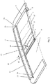
- FIG 2 one half of an open roof construction is illustrated which, as shown in figure 1 , generally comprises a roof opening 1 in a stationary roof part 2, a movable panel 3 which can move relative to said roof opening 1 (by means known per se and not shown here) and a rollo assembly to be elucidated below (of which in figure 1 only an operating beam 9 is visible).
- the rollo assembly comprises a rollo screen 4 (made for example of a cloth material) which is movable between a position for freeing said roof opening 1 and a position for closing (or obscuring) said roof opening.
- the rollo screen 4 has a forward side 5, an opposite rearward side 6 and two opposite lateral sides 7 (of which obviously only one has been shown).
- a winding tube 8 is provided for winding and unwinding the rollo screen 4 at the rearward side 6.
- An operating beam 9 is connected to the forward side 5 and has two outer ends 10 (of which obviously only one has been shown). Further two longitudinally extending guides 11 (of which obviously only one has been shown) are illustrated for guiding respective ones of the outer ends 10 of the operating beam 9 and respective ones of the lateral sides 7 of the rollo screen 4.
- the lateral sides 7 of the rollo screen 4 are provided with retention members cooperating with corresponding parts of the guides 11 for retaining said lateral sides 7 in said guides 11.
- the rollo screen 4 is provided with light transmitting and emitting members 12 which have an end portion 13 extending at least up to a first one of the lateral sides 7 of the rollo screen 4.
- These members 12 may be provided in the rollo screen 4 in any desired pattern and it is conceivable that the entire rollo screen 4 or only some parts thereof are provided with such members 12.
- At least the guide 11 intended for guiding said first one of the lateral sides 7 of the rollo screen 4 is provided with at least one elongate light bar 14 extending longitudinally along said guide 11 in such a position that it can transmit light into said end portion 13 of the light transmitting and emitting members 12.
- the elongate light bar 14 comprises two opposite frontal ends 15 and a light source 16 (for example an LED) is positioned at each of said ends 15.
- the light emitted by the light sources 16 enters the light bar 14 at said frontal ends 15 and is emitted by the light bar 14 over its entire length and will enter the end portions 13 of the members 12 which will transmit (distribute) and emit the light over the rollo screen 4 in accordance with their pattern over the rollo screen.
- the light bars 14 preferably are provided with means for improving the transmission of light into said end portions 13 only, as will appear later.
- both guides 11 are provided with a light bar 14 for cooperation with respective end portions 13 of light transmitting and emitting members 12 in the vicinity of both lateral sides 7 of the rollo screen 4.
- the light bars 14 may comprise injection moulded parts with a cross sectional area between 4 and 40 mm 2 , and preferably between 4 and 10 mm 2 , per each meter of length of a said light bar.
- the cross section of the light bars 14 may have any desired shape, such as circular, square, rectangular, oval or even other, more irregular, shapes, as will appear later.
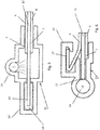
- figures 3-13 which, schematically and in part, illustrate cross sections (as viewed in a longitudinal direction according to A-A in figure 2 ) of different embodiments in a region of a guide 11.
- Figure 3 shows an embodiment of a rollo assembly not belonging to the invention in which the end portion 13 of the light transmitting and emitting members 12 substantially ends at the respective lateral side 7 of the rollo screen 4.
- the elongate light bar 14 is located laterally with respect to the respective lateral side 7 of the rollo screen 4 and is housed in a correspondingly shaped part of the guide 11.
- Figure 3 further shows a hook-like retention member 17 cooperating with a respective part 11' of the guide 11.
- the retention member 17 is provided on the upper surface of the rollo screen 4, but in other embodiments it may be located on the lower surface (e.g. figure 7 ) or on both (e.g. figure 8 ).
- the retention member 17 may be a separate part attached to the rollo screen 4 in any appropriate manner, or may be an integral part thereof (for example a folded back part).
- the retention member 17 does not interfere with the operation of the light bar 14.
- the retention member 17 also may protrude transversally beyond the end 13 of the members 12.
- the figures 5-10 all illustrate embodiments in which said end portion 13 of the light transmitting and emitting members 12 protrudes laterally beyond the respective lateral side 7 of the rollo screen 4.
- this embodiment not belonging to the invention comprises a retention member 18 provided at an outer end of the protruding end 13 and cooperating with a corresponding part 11' of the guide.
- Figure 6 illustrates an embodiment not belonging to the invention in which the elongate light bar 14 is located laterally with respect to the respective protruding end portion 13.
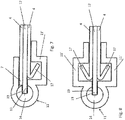
- FIGS 7-10 relate to embodiments in accordance with the invention in which the elongate light bar 14 is provided with a recess 19 extending longitudinally and intended for at least partially receiving said protruding end portion 13.
- a single retention member 17 is provided on a lower surface of the rollo screen 4
- two retention members 17 are provided, both on the upper and lower surface of the rollo screen 4.
- FIGS 9 and 10 special embodiments of the light bar 14 are shown.
- the light bar 14 has a square cross section and at least a part of the outer surface of the light bar is covered with a light reflecting layer 20 (for example a white layer) for improving the efficiency of the light bar (assuring that light only is emitted towards the end portion 13).
- a light reflecting layer 20 for example a white layer
- layer 20 may be replaced by a roughening or protruding (preferably triangular) parts.
- such a reflecting layer 20 is provided on the entire outer surface of the light bar 14 (which in this embodiment has a circular cross section). Further, in this embodiment, the recess 19 is provided with chamfered walls 21 for even more increasing the efficiency of the light bar 14.
- the light transmitting and emitting members 12 are illustrated as sandwiched between two layers of the rollo screen 4. However, also other embodiments are conceivable, for example wherein the members 12 are provided on top or below the rollo screen 4. As another alternative the light transmitting and emitting members 12 may comprise glass fibres oriented transversally and preferably woven into the rollo screen 4.
- the light transmitting and emitting members 12 may be combined into a single flexible foil (having light transmitting and emitting characteristics) which in figure 1 in broken lines has been indicated as foil 12'.
- a foil 12' may be adhered to one side of the rollo screen 4, preferably the lower side (facing an interior of the vehicle), but also may be sandwiched between two rollo screen layers.
- FIGs 11-13 illustrate embodiments in which the light bar 14 tapers towards the end portion 13.
- the light bar 14 in figure 11 not belonging to the invention the light bar 14 as a result has a bottle shaped cross section.
- the light bar tapers and has a recess 19 in its tapering part which therefore partly surrounds the end portion 13.
- the tapering part frontally faces the end portion 13.
- a guide is provided with more than one light bar, which light bars may be positioned at different positions relative to the end portion of the light transmitting and emitting members.
Landscapes
- Engineering & Computer Science (AREA)
- Mechanical Engineering (AREA)
- Operating, Guiding And Securing Of Roll- Type Closing Members (AREA)
- Light Guides In General And Applications Therefor (AREA)
Claims (12)
- Ensemble roulant destiné à une utilisation dans une construction de toit ouvrant pour un véhicule, comprenant un rideau roulant (4) ayant des côtés vers l'avant (5) et vers l'arrière (6) opposés et deux côtés latéraux opposés (7), un tube d'enroulement (8) pour enrouler et dérouler le rideau roulant au niveau du côté vers l'arrière, une traverse opérationnelle (9) raccordée au côté vers l'avant et ayant deux extrémités externes (10), et deux guides en extension longitudinale (11) pour guider des extrémités respectives des extrémités externes (10) de la traverse opérationnelle (9) et des côtés respectifs des côtés latéraux (7) du rideau roulant (4), dans lequel lesdits côtés latéraux sont munis d'organes de retenue (17; 18) coopérant avec des parties correspondantes (11') des guides (11) pour retenir lesdits côtés latéraux dans lesdits guides, dans lequel le rideau roulant (4) est muni d'organes de transmission et d'émission de lumière (12) qui ont une portion d'extrémité (13) en extension au moins jusqu'à un premier côté des côtés latéraux (7) du rideau roulant et dans lequel au moins le guide (11) destiné à guider ledit premier côté des côtés latéraux est muni d'au moins une rampe lumineuse allongée (14) en extension longitudinale suivant ledit guide dans une position telle qu'elle peut transmettre de la lumière dans ladite portion d'extrémité desdits organes de transmission et d'émission de lumière (12), caractérisé en ce que ladite portion d'extrémité (13) des organes de transmission et d'émission de lumière (12) fait saillie latéralement au-delà du côté latéral (7) respectif du rideau roulant (4) et dans lequel la rampe lumineuse allongée (14) est située latéralement vis-à-vis de la portion d'extrémité en saillie (13) respective et dans lequel la rampe lumineuse allongée (14) est munie d'un retrait (19) en extension longitudinale et destiné à recevoir au moins partiellement ladite portion d'extrémité en saillie (13).
- Ensemble roulant selon la revendication 1, dans lequel ledit retrait (19) est muni de parois chanfreinées (21).
- Ensemble roulant selon l'une quelconque des revendications précédentes, dans lequel la rampe lumineuse allongée (14) comprend deux extrémités frontales opposées (15) et dans lequel une source de lumière (16) est positionnée au niveau d'au moins l'une desdites extrémités frontales.
- Ensemble roulant selon l'une quelconque des revendications précédentes, dans lequel les deux guides (11) sont munis d'une rampe lumineuse (14) pour une coopération avec des portions d'extrémité (13) respectives d'organes de transmission et d'émission de lumière (12) au voisinage des deux côtés latéraux (7) du rideau roulant (4).
- Ensemble roulant selon l'une quelconque des revendications précédentes, dans lequel les organes de retenue (17) comprennent des organes de retenue de type crochet coopérant avec des parties respectives (11') des guides (11) et prévus au niveau d'au moins l'une des surfaces supérieure et inférieure du rideau roulant (4).
- Ensemble roulant selon l'une quelconque des revendications précédentes, dans lequel les rampes lumineuses (14) comprennent des parties moulées par injection avec une aire en section transversale comprise entre 4 et 40 mm2, et de préférence entre 4 et 10 mm2, pour chaque mètre de longueur de ladite rampe lumineuse.
- Ensemble roulant selon l'une quelconque des revendications précédentes, dans lequel les rampes lumineuses (14) ont une surface externe qui est munie au moins partiellement, de préférence à l'opposé de ladite portion d'extrémité (13), de moyens permettant d'améliorer la transmission de lumière dans ladite portion d'extrémité (13), telle qu'une couche réfléchissant la lumière (20), une pièce de rugosité ou, de préférence triangulaire en saillie.
- Ensemble roulant selon l'une quelconque des revendications précédentes, dans lequel les rampes lumineuses (14) ont une section transversale qui, dans une direction vers la portion d'extrémité (13), est effilée jusqu'à une épaisseur réduite, de préférence sensiblement jusqu'à l'épaisseur de la portion d'extrémité.
- Ensemble roulant selon l'une quelconque des revendications précédentes, dans lequel les organes de transmission et d'émission de lumière (12) sont positionnés au niveau du côté du rideau roulant (4) tourné vers un intérieur du véhicule.
- Ensemble roulant selon l'une quelconque des revendications précédentes, dans lequel les organes de transmission et d'émission de lumière (12) comprennent des fibres de verre orientées transversalement et de préférence tissées dans le rideau roulant (4).
- Ensemble roulant selon l'une quelconque des revendications 1 à 9, dans lequel les organes de transmission et d'émission de lumière (12) sont combinés en une feuille flexible unique (12'), qui est de préférence collée au côté du rideau roulant (4) tourné vers un intérieur du véhicule.
- Construction de toit ouvrant pour un véhicule, comprenant une ouverture de toit (1) dans une partie de toit fixe (2), un panneau mobile (3) qui peut se déplacer par rapport à ladite ouverture de toit et un ensemble roulant selon l'une quelconque des revendications précédentes dont le rideau roulant (4) est mobile entre une position pour dégager ladite ouverture de toit (1) et une position pour fermer ladite ouverture de toit.
Priority Applications (3)
| Application Number | Priority Date | Filing Date | Title |
|---|---|---|---|
| EP15178560.7A EP3132955B1 (fr) | 2015-07-28 | 2015-07-28 | Mecanisme d'enroulement et construction de toit ouvrant pour vehicule comprenant celui-ci |
| CN201610389500.8A CN106394202B (zh) | 2015-07-28 | 2016-06-03 | 卷帘组件以及设有卷帘组件的、用于车辆的开放式顶板结构 |
| US15/184,623 US9815354B2 (en) | 2015-07-28 | 2016-06-16 | Rollo assembly and open roof construction for a vehicle provided therewith |
Applications Claiming Priority (1)
| Application Number | Priority Date | Filing Date | Title |
|---|---|---|---|
| EP15178560.7A EP3132955B1 (fr) | 2015-07-28 | 2015-07-28 | Mecanisme d'enroulement et construction de toit ouvrant pour vehicule comprenant celui-ci |
Publications (2)
| Publication Number | Publication Date |
|---|---|
| EP3132955A1 EP3132955A1 (fr) | 2017-02-22 |
| EP3132955B1 true EP3132955B1 (fr) | 2020-04-08 |
Family
ID=53762021
Family Applications (1)
| Application Number | Title | Priority Date | Filing Date |
|---|---|---|---|
| EP15178560.7A Active EP3132955B1 (fr) | 2015-07-28 | 2015-07-28 | Mecanisme d'enroulement et construction de toit ouvrant pour vehicule comprenant celui-ci |
Country Status (3)
| Country | Link |
|---|---|
| US (1) | US9815354B2 (fr) |
| EP (1) | EP3132955B1 (fr) |
| CN (1) | CN106394202B (fr) |
Families Citing this family (9)
| Publication number | Priority date | Publication date | Assignee | Title |
|---|---|---|---|---|
| CN205697099U (zh) * | 2016-04-20 | 2016-11-23 | 皇田工业股份有限公司 | 发光布帘装置 |
| DE112018002386A5 (de) * | 2017-05-11 | 2020-01-23 | Bos Gmbh & Co. Kg | Schutzvorrichtung für einen Kraftfahrzeuginnenraum |
| DE102019129752B4 (de) | 2018-11-06 | 2023-08-10 | Webasto SE | Fahrzeugrollovorrichtung mit einer Beleuchtungseinrichtung |
| CN109435652A (zh) * | 2018-12-24 | 2019-03-08 | 上海毓恬冠佳汽车零部件有限公司 | 一种用于机动车车顶的遮阳帘装置 |
| DE102019112013B4 (de) * | 2019-05-08 | 2021-09-23 | Gebrüder Jaeger GmbH | Anbindungsband zum Anbinden eines Beschattungsmaterials an eine Führung und Verfahren |
| CN110920359B (zh) * | 2019-11-18 | 2021-06-01 | 宁波帅特龙集团有限公司 | 一种遮阳帘包边结构 |
| DE102020102354A1 (de) | 2020-01-31 | 2021-08-05 | Bayerische Motoren Werke Aktiengesellschaft | Beleuchtungssystem zur Illumination eines Dachhimmels eines Fahrzeugs, Fahrzeug mit einem derartigen Beleuchtungssystem sowie Verfahren zur Illumination eines Dachhimmels |
| DE102021203478A1 (de) * | 2021-04-08 | 2022-10-13 | Bos Gmbh & Co. Kg | Schutzvorrichtung für einen Kraftfahrzeuginnenraum |
| CN113547902B (zh) * | 2021-06-30 | 2023-06-27 | 宁波尚宏汽车天窗有限公司 | 一种发光遮阳帘布总成 |
Family Cites Families (14)
| Publication number | Priority date | Publication date | Assignee | Title |
|---|---|---|---|---|
| DE29908994U1 (de) * | 1999-05-21 | 1999-07-29 | Reitter & Schefenacker GmbH & Co. KG, 73730 Esslingen | Innenraumbeleuchtung von Fahrzeugen, vorzugsweise von Kraftfahrzeugen |
| DE19936537B4 (de) * | 1999-08-03 | 2005-07-14 | Daimlerchrysler Ag | Abschirmeinrichtung |
| US6631943B2 (en) * | 2001-01-26 | 2003-10-14 | Mueller Hermann-Frank | Sliding roof for motor vehicles |
| US6863424B2 (en) * | 2002-08-07 | 2005-03-08 | Whelen Engineering Company, Inc. | Light bar with integrated warning illumination and lens support structure |
| DE102004046386A1 (de) * | 2004-09-24 | 2006-04-06 | Schefenacker Vision Systems Germany Gmbh & Co. Kg | Lichtleiter für Leuchten, insbesondere für Leuchten von Kraftfahrzeugen |
| DE102005015602A1 (de) * | 2005-04-05 | 2006-10-12 | Webasto Ag | Abschattungsanordnung für eine lichtdurchlässige Fahrzeugkarosseriefläche |
| KR20100020318A (ko) * | 2008-08-12 | 2010-02-22 | 현대자동차주식회사 | 자동차용 선루프 |
| FR2948068B1 (fr) * | 2009-07-15 | 2012-10-26 | Peugeot Citroen Automobiles Sa | Dispositif d'occultation d'un pavillon de vehicule a guide(s) de lumiere integre(s) |
| DE102009033885B4 (de) * | 2009-07-20 | 2016-11-03 | Macauto Industrial Co., Ltd. | Fahrzeugdach-Rolloanordnung |
| US8419119B2 (en) * | 2010-10-26 | 2013-04-16 | Yachiyo Industry Co., Ltd. | Sunshade device |
| FR2991931B1 (fr) * | 2012-06-18 | 2015-01-09 | Webasto Systemes Carrosserie | Dispositif d'occultation comportant une source de lumiere |
| DE102013104341B4 (de) * | 2013-04-29 | 2020-07-02 | Webasto SE | Rolloanordnung für ein Fahrzeug |
| DE102013011605B4 (de) * | 2013-07-11 | 2015-02-12 | Webasto SE | Rolloanordnung mit integrierter Beleuchtung |
| US20170010404A1 (en) * | 2015-07-09 | 2017-01-12 | Pixon Technologies Corp. | Linear light source with flexible printed circuit |
-
2015
- 2015-07-28 EP EP15178560.7A patent/EP3132955B1/fr active Active
-
2016
- 2016-06-03 CN CN201610389500.8A patent/CN106394202B/zh active Active
- 2016-06-16 US US15/184,623 patent/US9815354B2/en active Active
Non-Patent Citations (1)
| Title |
|---|
| None * |
Also Published As
| Publication number | Publication date |
|---|---|
| US9815354B2 (en) | 2017-11-14 |
| CN106394202B (zh) | 2021-06-18 |
| US20170028826A1 (en) | 2017-02-02 |
| CN106394202A (zh) | 2017-02-15 |
| EP3132955A1 (fr) | 2017-02-22 |
Similar Documents
| Publication | Publication Date | Title |
|---|---|---|
| EP3132955B1 (fr) | Mecanisme d'enroulement et construction de toit ouvrant pour vehicule comprenant celui-ci | |
| US9987980B2 (en) | Covering device with a light source | |
| US10202073B2 (en) | Shading arrangement of a vehicle roof | |
| US11203255B2 (en) | Protection device for a motor vehicle interior | |
| GB2475940A (en) | Illuminating device for a vehicle | |
| EP2135761B1 (fr) | Structure de toit de vehicule | |
| JP6094238B2 (ja) | 車両用灯具 | |
| EP2990720A1 (fr) | Unité d'éclairage de véhicule | |
| JP2016091846A (ja) | 車両用灯具 | |
| EP3012522A1 (fr) | Unité d'éclairage de véhicule | |
| JP2011076858A (ja) | 車輌用灯具 | |
| EP3495204B1 (fr) | Structure décapotable pour véhicule | |
| CN112739565B (zh) | 具有导光体照明元件的车顶 | |
| US20180283638A1 (en) | Light emitting device and moving object | |
| US10234615B2 (en) | Illumination device | |
| CN113439178B (zh) | 灯单元和车灯 | |
| EP2902260A2 (fr) | Toit ouvrant pour véhicule et store à enrouleur pour ce toit | |
| JPWO2018038015A1 (ja) | 車両用灯具 | |
| US12146632B2 (en) | Exterior luminaire for a motor vehicle | |
| CN215597201U (zh) | 发光组件、车灯和车辆 | |
| JP5445091B2 (ja) | 車両用照明装置 | |
| US20220266742A1 (en) | Vehicle lamp body device | |
| JP6344706B2 (ja) | 昇降収納装置 | |
| JP2012069335A (ja) | エッジライト式発光装置 | |
| JP6619584B2 (ja) | 導光体 |
Legal Events
| Date | Code | Title | Description |
|---|---|---|---|
| PUAI | Public reference made under article 153(3) epc to a published international application that has entered the european phase |
Free format text: ORIGINAL CODE: 0009012 |
|
| STAA | Information on the status of an ep patent application or granted ep patent |
Free format text: STATUS: THE APPLICATION HAS BEEN PUBLISHED |
|
| AK | Designated contracting states |
Kind code of ref document: A1 Designated state(s): AL AT BE BG CH CY CZ DE DK EE ES FI FR GB GR HR HU IE IS IT LI LT LU LV MC MK MT NL NO PL PT RO RS SE SI SK SM TR |
|
| AX | Request for extension of the european patent |
Extension state: BA ME |
|
| STAA | Information on the status of an ep patent application or granted ep patent |
Free format text: STATUS: REQUEST FOR EXAMINATION WAS MADE |
|
| 17P | Request for examination filed |
Effective date: 20170721 |
|
| RBV | Designated contracting states (corrected) |
Designated state(s): AL AT BE BG CH CY CZ DE DK EE ES FI FR GB GR HR HU IE IS IT LI LT LU LV MC MK MT NL NO PL PT RO RS SE SI SK SM TR |
|
| GRAP | Despatch of communication of intention to grant a patent |
Free format text: ORIGINAL CODE: EPIDOSNIGR1 |
|
| STAA | Information on the status of an ep patent application or granted ep patent |
Free format text: STATUS: GRANT OF PATENT IS INTENDED |
|
| INTG | Intention to grant announced |
Effective date: 20191122 |
|
| GRAS | Grant fee paid |
Free format text: ORIGINAL CODE: EPIDOSNIGR3 |
|
| GRAA | (expected) grant |
Free format text: ORIGINAL CODE: 0009210 |
|
| STAA | Information on the status of an ep patent application or granted ep patent |
Free format text: STATUS: THE PATENT HAS BEEN GRANTED |
|
| AK | Designated contracting states |
Kind code of ref document: B1 Designated state(s): AL AT BE BG CH CY CZ DE DK EE ES FI FR GB GR HR HU IE IS IT LI LT LU LV MC MK MT NL NO PL PT RO RS SE SI SK SM TR |
|
| REG | Reference to a national code |
Ref country code: CH Ref legal event code: EP Ref country code: AT Ref legal event code: REF Ref document number: 1253898 Country of ref document: AT Kind code of ref document: T Effective date: 20200415 |
|
| REG | Reference to a national code |
Ref country code: DE Ref legal event code: R096 Ref document number: 602015050165 Country of ref document: DE |
|
| REG | Reference to a national code |
Ref country code: IE Ref legal event code: FG4D |
|
| REG | Reference to a national code |
Ref country code: NL Ref legal event code: MP Effective date: 20200408 |
|
| REG | Reference to a national code |
Ref country code: LT Ref legal event code: MG4D |
|
| PG25 | Lapsed in a contracting state [announced via postgrant information from national office to epo] |
Ref country code: PT Free format text: LAPSE BECAUSE OF FAILURE TO SUBMIT A TRANSLATION OF THE DESCRIPTION OR TO PAY THE FEE WITHIN THE PRESCRIBED TIME-LIMIT Effective date: 20200817 Ref country code: NL Free format text: LAPSE BECAUSE OF FAILURE TO SUBMIT A TRANSLATION OF THE DESCRIPTION OR TO PAY THE FEE WITHIN THE PRESCRIBED TIME-LIMIT Effective date: 20200408 Ref country code: LT Free format text: LAPSE BECAUSE OF FAILURE TO SUBMIT A TRANSLATION OF THE DESCRIPTION OR TO PAY THE FEE WITHIN THE PRESCRIBED TIME-LIMIT Effective date: 20200408 Ref country code: NO Free format text: LAPSE BECAUSE OF FAILURE TO SUBMIT A TRANSLATION OF THE DESCRIPTION OR TO PAY THE FEE WITHIN THE PRESCRIBED TIME-LIMIT Effective date: 20200708 Ref country code: FI Free format text: LAPSE BECAUSE OF FAILURE TO SUBMIT A TRANSLATION OF THE DESCRIPTION OR TO PAY THE FEE WITHIN THE PRESCRIBED TIME-LIMIT Effective date: 20200408 Ref country code: GR Free format text: LAPSE BECAUSE OF FAILURE TO SUBMIT A TRANSLATION OF THE DESCRIPTION OR TO PAY THE FEE WITHIN THE PRESCRIBED TIME-LIMIT Effective date: 20200709 Ref country code: SE Free format text: LAPSE BECAUSE OF FAILURE TO SUBMIT A TRANSLATION OF THE DESCRIPTION OR TO PAY THE FEE WITHIN THE PRESCRIBED TIME-LIMIT Effective date: 20200408 Ref country code: IS Free format text: LAPSE BECAUSE OF FAILURE TO SUBMIT A TRANSLATION OF THE DESCRIPTION OR TO PAY THE FEE WITHIN THE PRESCRIBED TIME-LIMIT Effective date: 20200808 |
|
| REG | Reference to a national code |
Ref country code: AT Ref legal event code: MK05 Ref document number: 1253898 Country of ref document: AT Kind code of ref document: T Effective date: 20200408 |
|
| PG25 | Lapsed in a contracting state [announced via postgrant information from national office to epo] |
Ref country code: BG Free format text: LAPSE BECAUSE OF FAILURE TO SUBMIT A TRANSLATION OF THE DESCRIPTION OR TO PAY THE FEE WITHIN THE PRESCRIBED TIME-LIMIT Effective date: 20200708 Ref country code: LV Free format text: LAPSE BECAUSE OF FAILURE TO SUBMIT A TRANSLATION OF THE DESCRIPTION OR TO PAY THE FEE WITHIN THE PRESCRIBED TIME-LIMIT Effective date: 20200408 Ref country code: RS Free format text: LAPSE BECAUSE OF FAILURE TO SUBMIT A TRANSLATION OF THE DESCRIPTION OR TO PAY THE FEE WITHIN THE PRESCRIBED TIME-LIMIT Effective date: 20200408 Ref country code: HR Free format text: LAPSE BECAUSE OF FAILURE TO SUBMIT A TRANSLATION OF THE DESCRIPTION OR TO PAY THE FEE WITHIN THE PRESCRIBED TIME-LIMIT Effective date: 20200408 |
|
| PG25 | Lapsed in a contracting state [announced via postgrant information from national office to epo] |
Ref country code: AL Free format text: LAPSE BECAUSE OF FAILURE TO SUBMIT A TRANSLATION OF THE DESCRIPTION OR TO PAY THE FEE WITHIN THE PRESCRIBED TIME-LIMIT Effective date: 20200408 |
|
| REG | Reference to a national code |
Ref country code: DE Ref legal event code: R097 Ref document number: 602015050165 Country of ref document: DE |
|
| PG25 | Lapsed in a contracting state [announced via postgrant information from national office to epo] |
Ref country code: DK Free format text: LAPSE BECAUSE OF FAILURE TO SUBMIT A TRANSLATION OF THE DESCRIPTION OR TO PAY THE FEE WITHIN THE PRESCRIBED TIME-LIMIT Effective date: 20200408 Ref country code: EE Free format text: LAPSE BECAUSE OF FAILURE TO SUBMIT A TRANSLATION OF THE DESCRIPTION OR TO PAY THE FEE WITHIN THE PRESCRIBED TIME-LIMIT Effective date: 20200408 Ref country code: AT Free format text: LAPSE BECAUSE OF FAILURE TO SUBMIT A TRANSLATION OF THE DESCRIPTION OR TO PAY THE FEE WITHIN THE PRESCRIBED TIME-LIMIT Effective date: 20200408 Ref country code: SM Free format text: LAPSE BECAUSE OF FAILURE TO SUBMIT A TRANSLATION OF THE DESCRIPTION OR TO PAY THE FEE WITHIN THE PRESCRIBED TIME-LIMIT Effective date: 20200408 Ref country code: ES Free format text: LAPSE BECAUSE OF FAILURE TO SUBMIT A TRANSLATION OF THE DESCRIPTION OR TO PAY THE FEE WITHIN THE PRESCRIBED TIME-LIMIT Effective date: 20200408 Ref country code: RO Free format text: LAPSE BECAUSE OF FAILURE TO SUBMIT A TRANSLATION OF THE DESCRIPTION OR TO PAY THE FEE WITHIN THE PRESCRIBED TIME-LIMIT Effective date: 20200408 Ref country code: CZ Free format text: LAPSE BECAUSE OF FAILURE TO SUBMIT A TRANSLATION OF THE DESCRIPTION OR TO PAY THE FEE WITHIN THE PRESCRIBED TIME-LIMIT Effective date: 20200408 Ref country code: IT Free format text: LAPSE BECAUSE OF FAILURE TO SUBMIT A TRANSLATION OF THE DESCRIPTION OR TO PAY THE FEE WITHIN THE PRESCRIBED TIME-LIMIT Effective date: 20200408 |
|
| PLBE | No opposition filed within time limit |
Free format text: ORIGINAL CODE: 0009261 |
|
| STAA | Information on the status of an ep patent application or granted ep patent |
Free format text: STATUS: NO OPPOSITION FILED WITHIN TIME LIMIT |
|
| PG25 | Lapsed in a contracting state [announced via postgrant information from national office to epo] |
Ref country code: MC Free format text: LAPSE BECAUSE OF FAILURE TO SUBMIT A TRANSLATION OF THE DESCRIPTION OR TO PAY THE FEE WITHIN THE PRESCRIBED TIME-LIMIT Effective date: 20200408 Ref country code: SK Free format text: LAPSE BECAUSE OF FAILURE TO SUBMIT A TRANSLATION OF THE DESCRIPTION OR TO PAY THE FEE WITHIN THE PRESCRIBED TIME-LIMIT Effective date: 20200408 Ref country code: PL Free format text: LAPSE BECAUSE OF FAILURE TO SUBMIT A TRANSLATION OF THE DESCRIPTION OR TO PAY THE FEE WITHIN THE PRESCRIBED TIME-LIMIT Effective date: 20200408 |
|
| REG | Reference to a national code |
Ref country code: CH Ref legal event code: PL |
|
| 26N | No opposition filed |
Effective date: 20210112 |
|
| GBPC | Gb: european patent ceased through non-payment of renewal fee |
Effective date: 20200728 |
|
| REG | Reference to a national code |
Ref country code: BE Ref legal event code: MM Effective date: 20200731 |
|
| PG25 | Lapsed in a contracting state [announced via postgrant information from national office to epo] |
Ref country code: LU Free format text: LAPSE BECAUSE OF NON-PAYMENT OF DUE FEES Effective date: 20200728 Ref country code: LI Free format text: LAPSE BECAUSE OF NON-PAYMENT OF DUE FEES Effective date: 20200731 Ref country code: GB Free format text: LAPSE BECAUSE OF NON-PAYMENT OF DUE FEES Effective date: 20200728 Ref country code: CH Free format text: LAPSE BECAUSE OF NON-PAYMENT OF DUE FEES Effective date: 20200731 |
|
| PG25 | Lapsed in a contracting state [announced via postgrant information from national office to epo] |
Ref country code: BE Free format text: LAPSE BECAUSE OF NON-PAYMENT OF DUE FEES Effective date: 20200731 Ref country code: SI Free format text: LAPSE BECAUSE OF FAILURE TO SUBMIT A TRANSLATION OF THE DESCRIPTION OR TO PAY THE FEE WITHIN THE PRESCRIBED TIME-LIMIT Effective date: 20200408 |
|
| PG25 | Lapsed in a contracting state [announced via postgrant information from national office to epo] |
Ref country code: IE Free format text: LAPSE BECAUSE OF NON-PAYMENT OF DUE FEES Effective date: 20200728 |
|
| PG25 | Lapsed in a contracting state [announced via postgrant information from national office to epo] |
Ref country code: TR Free format text: LAPSE BECAUSE OF FAILURE TO SUBMIT A TRANSLATION OF THE DESCRIPTION OR TO PAY THE FEE WITHIN THE PRESCRIBED TIME-LIMIT Effective date: 20200408 Ref country code: MT Free format text: LAPSE BECAUSE OF FAILURE TO SUBMIT A TRANSLATION OF THE DESCRIPTION OR TO PAY THE FEE WITHIN THE PRESCRIBED TIME-LIMIT Effective date: 20200408 Ref country code: CY Free format text: LAPSE BECAUSE OF FAILURE TO SUBMIT A TRANSLATION OF THE DESCRIPTION OR TO PAY THE FEE WITHIN THE PRESCRIBED TIME-LIMIT Effective date: 20200408 |
|
| PG25 | Lapsed in a contracting state [announced via postgrant information from national office to epo] |
Ref country code: MK Free format text: LAPSE BECAUSE OF FAILURE TO SUBMIT A TRANSLATION OF THE DESCRIPTION OR TO PAY THE FEE WITHIN THE PRESCRIBED TIME-LIMIT Effective date: 20200408 |
|
| PGFP | Annual fee paid to national office [announced via postgrant information from national office to epo] |
Ref country code: DE Payment date: 20250729 Year of fee payment: 11 |
|
| PGFP | Annual fee paid to national office [announced via postgrant information from national office to epo] |
Ref country code: FR Payment date: 20250728 Year of fee payment: 11 |