EP3132965B1 - Atc-antennenvorrichtung, atc-signal-übertragungsvorrichtung und fahrzeug - Google Patents
Atc-antennenvorrichtung, atc-signal-übertragungsvorrichtung und fahrzeug Download PDFInfo
- Publication number
- EP3132965B1 EP3132965B1 EP14892564.7A EP14892564A EP3132965B1 EP 3132965 B1 EP3132965 B1 EP 3132965B1 EP 14892564 A EP14892564 A EP 14892564A EP 3132965 B1 EP3132965 B1 EP 3132965B1
- Authority
- EP
- European Patent Office
- Prior art keywords
- atc
- atc antenna
- antenna
- antenna support
- coils
- Prior art date
- Legal status (The legal status is an assumption and is not a legal conclusion. Google has not performed a legal analysis and makes no representation as to the accuracy of the status listed.)
- Active
Links
Images


Classifications
-
- H—ELECTRICITY
- H01—ELECTRIC ELEMENTS
- H01Q—ANTENNAS, i.e. RADIO AERIALS
- H01Q1/00—Details of, or arrangements associated with, antennas
- H01Q1/27—Adaptation for use in or on movable bodies
- H01Q1/32—Adaptation for use in or on road or rail vehicles
- H01Q1/325—Adaptation for use in or on road or rail vehicles characterised by the location of the antenna on the vehicle
- H01Q1/3291—Adaptation for use in or on road or rail vehicles characterised by the location of the antenna on the vehicle mounted in or on other locations inside the vehicle or vehicle body
-
- B—PERFORMING OPERATIONS; TRANSPORTING
- B60—VEHICLES IN GENERAL
- B60L—PROPULSION OF ELECTRICALLY-PROPELLED VEHICLES; SUPPLYING ELECTRIC POWER FOR AUXILIARY EQUIPMENT OF ELECTRICALLY-PROPELLED VEHICLES; ELECTRODYNAMIC BRAKE SYSTEMS FOR VEHICLES IN GENERAL; MAGNETIC SUSPENSION OR LEVITATION FOR VEHICLES; MONITORING OPERATING VARIABLES OF ELECTRICALLY-PROPELLED VEHICLES; ELECTRIC SAFETY DEVICES FOR ELECTRICALLY-PROPELLED VEHICLES
- B60L15/00—Methods, circuits, or devices for controlling the traction-motor speed of electrically-propelled vehicles
- B60L15/40—Adaptation of control equipment on vehicle for remote actuation from a stationary place
-
- B—PERFORMING OPERATIONS; TRANSPORTING
- B60—VEHICLES IN GENERAL
- B60L—PROPULSION OF ELECTRICALLY-PROPELLED VEHICLES; SUPPLYING ELECTRIC POWER FOR AUXILIARY EQUIPMENT OF ELECTRICALLY-PROPELLED VEHICLES; ELECTRODYNAMIC BRAKE SYSTEMS FOR VEHICLES IN GENERAL; MAGNETIC SUSPENSION OR LEVITATION FOR VEHICLES; MONITORING OPERATING VARIABLES OF ELECTRICALLY-PROPELLED VEHICLES; ELECTRIC SAFETY DEVICES FOR ELECTRICALLY-PROPELLED VEHICLES
- B60L3/00—Electric devices on electrically-propelled vehicles for safety purposes; Monitoring operating variables, e.g. speed, deceleration or energy consumption
- B60L3/0023—Detecting, eliminating, remedying or compensating for drive train abnormalities, e.g. failures within the drive train
- B60L3/003—Detecting, eliminating, remedying or compensating for drive train abnormalities, e.g. failures within the drive train relating to inverters
-
- B—PERFORMING OPERATIONS; TRANSPORTING
- B61—RAILWAYS
- B61L—GUIDING RAILWAY TRAFFIC; ENSURING THE SAFETY OF RAILWAY TRAFFIC
- B61L15/00—Indicators provided on the vehicle or train for signalling purposes
- B61L15/0062—On-board target speed calculation or supervision
-
- B—PERFORMING OPERATIONS; TRANSPORTING
- B61—RAILWAYS
- B61L—GUIDING RAILWAY TRAFFIC; ENSURING THE SAFETY OF RAILWAY TRAFFIC
- B61L27/00—Central railway traffic control systems; Trackside control; Communication systems specially adapted therefor
- B61L27/20—Trackside control of safe travel of vehicle or train, e.g. braking curve calculation
-
- B—PERFORMING OPERATIONS; TRANSPORTING
- B61—RAILWAYS
- B61L—GUIDING RAILWAY TRAFFIC; ENSURING THE SAFETY OF RAILWAY TRAFFIC
- B61L3/00—Devices along the route for controlling devices on the vehicle or train, e.g. to release brake or to operate a warning signal
- B61L3/02—Devices along the route for controlling devices on the vehicle or train, e.g. to release brake or to operate a warning signal at selected places along the route, e.g. intermittent control simultaneous mechanical and electrical control
- B61L3/08—Devices along the route for controlling devices on the vehicle or train, e.g. to release brake or to operate a warning signal at selected places along the route, e.g. intermittent control simultaneous mechanical and electrical control controlling electrically
- B61L3/12—Devices along the route for controlling devices on the vehicle or train, e.g. to release brake or to operate a warning signal at selected places along the route, e.g. intermittent control simultaneous mechanical and electrical control controlling electrically using magnetic or electrostatic induction; using radio waves
- B61L3/121—Devices along the route for controlling devices on the vehicle or train, e.g. to release brake or to operate a warning signal at selected places along the route, e.g. intermittent control simultaneous mechanical and electrical control controlling electrically using magnetic or electrostatic induction; using radio waves using magnetic induction
-
- B—PERFORMING OPERATIONS; TRANSPORTING
- B61—RAILWAYS
- B61L—GUIDING RAILWAY TRAFFIC; ENSURING THE SAFETY OF RAILWAY TRAFFIC
- B61L3/00—Devices along the route for controlling devices on the vehicle or train, e.g. to release brake or to operate a warning signal
- B61L3/02—Devices along the route for controlling devices on the vehicle or train, e.g. to release brake or to operate a warning signal at selected places along the route, e.g. intermittent control simultaneous mechanical and electrical control
- B61L3/08—Devices along the route for controlling devices on the vehicle or train, e.g. to release brake or to operate a warning signal at selected places along the route, e.g. intermittent control simultaneous mechanical and electrical control controlling electrically
- B61L3/12—Devices along the route for controlling devices on the vehicle or train, e.g. to release brake or to operate a warning signal at selected places along the route, e.g. intermittent control simultaneous mechanical and electrical control controlling electrically using magnetic or electrostatic induction; using radio waves
- B61L3/126—Constructional details
-
- H—ELECTRICITY
- H01—ELECTRIC ELEMENTS
- H01Q—ANTENNAS, i.e. RADIO AERIALS
- H01Q1/00—Details of, or arrangements associated with, antennas
- H01Q1/27—Adaptation for use in or on movable bodies
- H01Q1/32—Adaptation for use in or on road or rail vehicles
- H01Q1/3208—Adaptation for use in or on road or rail vehicles characterised by the application wherein the antenna is used
- H01Q1/3216—Adaptation for use in or on road or rail vehicles characterised by the application wherein the antenna is used where the road or rail vehicle is only used as transportation means
-
- H—ELECTRICITY
- H01—ELECTRIC ELEMENTS
- H01Q—ANTENNAS, i.e. RADIO AERIALS
- H01Q7/00—Loop antennas with a substantially uniform current distribution around the loop and having a directional radiation pattern in a plane perpendicular to the plane of the loop
-
- B—PERFORMING OPERATIONS; TRANSPORTING
- B60—VEHICLES IN GENERAL
- B60L—PROPULSION OF ELECTRICALLY-PROPELLED VEHICLES; SUPPLYING ELECTRIC POWER FOR AUXILIARY EQUIPMENT OF ELECTRICALLY-PROPELLED VEHICLES; ELECTRODYNAMIC BRAKE SYSTEMS FOR VEHICLES IN GENERAL; MAGNETIC SUSPENSION OR LEVITATION FOR VEHICLES; MONITORING OPERATING VARIABLES OF ELECTRICALLY-PROPELLED VEHICLES; ELECTRIC SAFETY DEVICES FOR ELECTRICALLY-PROPELLED VEHICLES
- B60L2200/00—Type of vehicles
- B60L2200/26—Rail vehicles
Definitions
- the present disclosure relates to an ATC antenna device, an ATC signal transmission device, and a car.
- ATC Automatic train control
- ATC ground device installed on a ground side
- Rolling stock is provided with an ATC antenna for receiving the speed signals.
- the ATC antenna is installed below the floor on the front portion of the lead car of rolling stock.
- the ATC antenna includes two antenna coils. These two antenna coils are disposed on the front side of a lead bogie and are directly above left and right rails.
- an ATC antenna is disposed below the floor on the front portion of the body of the lead car.
- the ATC antenna receives signals from the ATC ground device installed between the rails.
- Unexamined Japanese Patent Application Kokai Publication No. 2003-079011 does not specifically disclose the ATC antenna as the on-board device, the ATC antenna typically includes left and right antenna coils as mentioned above.
- the ATC ground device is typically a rectangular loop-shaped coil. This coil is installed such that the loop is horizontal between the left and right rails.
- the coil includes a coil side that is close to and parallel to the left rail and a coil side that is close to and parallel to the right rail.
- AC alternating current
- the ATC antenna moves above the rails together with the car. As such, when the ATC antenna passes over the ATC ground device, the AC magnetic flux generated at the ATC ground device induces AC voltage in the coils of the ATC antenna. A speed specified by a signal received from the ATC ground device is detected based on voltage that has a specific frequency component in the induced AC voltage and that exceeds a threshold. Then, the detected speed is used as a command speed for performing speed control of a train.
- the coil of the ATC ground device is loop shaped.
- the directions of current through the left and right coil sides are opposite to each other and the directions of voltage induced in the left and right ATC antenna coils are also opposite to each other. Therefore, provided that the left and right antenna coils of the ATC antenna are connected in series and are of opposite phase (to have opposite polarities of the voltage induced by magnetic lines oriented in the same direction), the induction voltages each generated at antenna coils are added together to be an amplified voltage, thereby improving speed detection sensitivity.
- Document US 3 493 741 A shows an object stopping system.
- Document GB 2 027 244 A shows a signalling device for guided vehicles.
- Inverter-driven rolling stock is recently predominant.
- a traction motor is driven by AC that flows from an inverter to the traction motor.
- the revolutions of the traction motor is adjusted, and the traveling speed of a car body is controlled.
- the present disclosure has been made in view of the foregoing, and an objective of the present disclosure to provide an ATC antenna device, an ATC signal transmission device, and a car capable of preventing the erroneous detection of the ATC speed signal caused by AC magnetic flux of fundamental waves and harmonic waves generated by AC flowing through the traction motor.
- an automatic train control antenna device is provided according to claim 1.
- a support for supporting a pair of ATC antenna coils is disposed asymmetrically with respect to a center line of a car body as viewed in the traveling direction of the car body.
- the paired ATC antenna coils are disposed symmetrically with respect to the center line of the car body and are connected in series and are of opposite phase.
- the support for supporting the paired antenna coils is asymmetrical with respect to the center line of the car body, and the paired antenna coils are symmetrical with respect to the center line of the car body and are connected in series and are of opposite phase.
- the AC magnetic flux of fundamental waves and harmonic waves which occurs at a cable and a traction motor body due to AC flowing through a traction motor, passes through the paired antenna coils in phase via the support.
- the paired antenna coils are connected in series and are of opposite phase, the induction voltages, which are caused by the AC magnetic flux occurring in each antenna coil in phase, cancel each other out. This, as a result, enables erroneous detection of ATC speed signals due to AC magnetic flux of fundamentals waves and harmonic waves generated by AC flowing through the traction motor to be prevented.
- Embodiment 1 of the present disclosure is described.
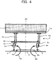
- FIG. 1 illustrates an ATC antenna device according to Embodiment 1 of the present disclosure, as viewed from the front of a car.
- FIG. 2 illustrates the ATC antenna device as viewed from a side of the car.
- FIG. 3 illustrates a control system for performing automatic train control (ATC).
- ATC automatic train control
- a body 1 is a body of rolling stock traveling on rails 3.
- An ATC antenna device 100 is attached to the bottom portion of an underfloor frame 1a of the body 1.
- the ATC antenna device 100 is provided on the body 1 of the lead car of rolling stock.
- the ATC antenna device 100 receives ATC signals (speed signals) from an ATC ground device 5 that is laid between the rails 3.
- the ATC antenna device 100 includes an ATC antenna 4 (a pair of ATC antenna coils 4a and 4b) disposed symmetrically with respect to a center line AX of the body 1 as viewed in the traveling direction of the body 1, and an ATC antenna support device 2 that is attached to the car to support the ATC antenna coils 4a and 4b and is asymmetrically disposed with respect to the center line AX.
- the ATC antenna support device 2 supports the paired ATC antenna coils 4a and 4b from the same lateral direction (right side in FIG. 1 ) as viewed in the traveling direction of the body 1.
- the ATC antenna support device 2 includes two vertically extending ATC antenna support bars 2a.
- the two ATC antenna support bars 2a are disposed to the right and to the left of the center line of the body 1 with a prescribed distance therebetween.
- the top end of the two ATC antenna support bars 2a are fixed to the bottom portion of the underfloor frame 1a.
- the ATC antenna support device 2 includes a horizontally extending ATC antenna support base 2b that is suspended from both bottom ends of the two ATC antenna support bars 2a.
- the ATC antenna support device 2 includes ATC antenna attaching members 2c both of which are disposed on the bottom portion of the ATC antenna support base 2b, and oriented in the same lateral direction.
- the ATC antenna 4, namely, the paired ATC antenna coils 4a and 4b are fixedly attached to the ATC antenna attaching members 2c, and are oriented in the same lateral direction.
- the ATC antenna support device 2 is integrally formed by the ATC antenna support bars 2a, the ATC antenna support base 2b, and the ATC antenna attaching members 2c, which are fastened or fixed together with bolts and the like, or welded together and the like.
- the left and right ATC antenna coils 4a and 4b of the ATC antenna 4 are attached to either the right side or the left side of the ATC antenna attaching members 2c.
- the ATC antenna support device 2 is formed in an asymmetrical shape with respect to the ATC antenna 4 (the paired ATC antenna coils 4a and 4b).
- the ATC antenna support device 2 is affixed with bolts and the like to the bottom portion of the underfloor frame 1a of the body 1.
- the position in the right-and-left direction of the ATC antenna support device 2 fixed to the underfloor frame 1a, as illustrated in FIG. 1 is not a position that is symmetrical with respect to the center of the body 1.
- the ATC antenna 4, namely, the paired ATC antenna coils 4a and 4b attached to the ATC antenna support device 2 are disposed symmetrically with respect to the center line AX of the body 1.
- the ATC ground device 5 is laid at a ground point between the left and right rails 3 to transmit speed signals to a car side for automatic train control.
- the ATC ground device 5 is a rectangular loop-shaped coil. This coil is installed such that the loop is horizontal between the left and right rails 3.
- the coil includes a coil side 5a that is close to and parallel to the left rail 3, and a coil side 5b that is close to and parallel to the right rail 3.
- a bogie frame 9 is installed on the bottom portion of the body 1. Wheels 10 are attached to the bogie frame 9.
- a traction motor 7 is mounted in the bogie frame 9. Rotary drive of the traction motor 7 causes the wheels 10 to rotate, thereby moving the body 1 along the rails 3.
- An inverter 15, which is installed beneath the floor of the body 1, and the traction motor 7 are connected together via traction motor cables 8. The traction motor 7 is driven by AC passing through the traction motor cables 8 from the inverter 15.
- the ATC antenna support device 2 is disposed in a front position separated from the bogie frame 9 by a prescribed distance.
- a rail guard 11 is installed on the bottom portion of the front-most area of the body 1.
- the ATC antenna support device 2 is installed between the rail guard 11 and the bogie frame 9.
- a ground transmitter 12 is provided on the ground side.
- AC flows from the ground transmitter 12 to the ATC ground device 5 at a frequency in accordance with a command speed to be transmitted.
- the electromagnetic coupling of the AC induces AC voltage in the antenna coils 4a and 4b of the ATC antenna 4 on the car side.
- a receiving circuit 13 and the ATC control device 14 thereby detect the command speed, and the command speed is then input to the inverter 15.
- the inverter 15 drives the traction motor 7 at this command speed.
- a different frequency is set for each target speed signal, and AC of the frequency corresponding to the command speed passes through the ATC ground device 5.
- AC When current flows through a conductive wire, magnetic flux occurs around the conductive wire in accordance with the right-hand screw rule. In the case of AC, AC magnetic flux occurs in which a direction changes at the same frequency as the current.
- AC magnetic fluxes 6a and 6b having the same frequency as the AC occurs around the coil sides 5a and 5b of the ATC ground device 5.
- the ATC ground device 5 is a loop shaped coil.
- the AC magnetic flux 6a, which occurs due to AC flowing through the left coil side 5a parallel to the rails 3, and the AC magnetic flux 6b, which occurs due to AC flowing through the right coil side 5b parallel to the rails 3, flow in directions opposite to each other as illustrated in FIG. 4 .
- Portions of the AC magnetic fluxes 6a and 6b, which occur due to the ATC ground device 5, pass through the ATC antenna 4.
- AC voltage is induced in the ATC antenna 4 due to the AC magnetic fluxes 6a and 6b.
- the AC magnetic flux 6a mainly passes through the ATC antenna coil 4a on the left, whereas the AC magnetic flux 6b mainly passes through the ATC antenna coil 4b on the right. Therefore, AC voltages are induced in opposite directions in the left and right ATC antenna coils 4a and 4b.
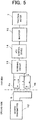
- the ATC antenna coils 4a and 4b on the left and right are connected in series and are of opposite phase as illustrated in FIG. 3 . As such, as illustrated in FIG. 5 , the AC voltages having opposite directions in the left and right ATC antenna coils 4a and 4b become a larger AC voltage amplified on the circuit where the AC voltages have the same polarity.
- the receiving circuit 13 detects a frequency based on the amplified AC voltage, which enables the ATC control device 14 to determine the command speed.
- the AC magnetic flux 6a which occurs due to AC flowing through the left coil side 5a, is what mainly passes through the left ATC antenna coil 4a, and the AC magnetic flux 6b, which occurs due to AC flowing through the right coil side 5b, also passes through the ATC antenna coil 4a.
- the distance between the left ATC antenna coil 4a and the right coil side 5b is greater than the distance between the left ATC antenna coil 4a and the left coil side 5a.
- the direction of return current flowing through the rails 3 is the same for the left and right rails and the direction of the resulting magnetic flux is also the same.
- return current is direct current, but when the magnitude of the current value changes and the magnitude of the resulting magnetic fluxes 16a and 16b changes, the voltage is induced in the ATC antenna 4.
- the AC voltages induced are also in phase and cancel each other out.
- the ATC antenna coils 4a and 4b are connected in series and are of opposite phase, the voltages are not erroneously detected as the ATC signals.
- the traction motor 7 is mounted on the bogie frame 9 that is near the ATC antenna 4 and the AC supplied from the inverter 15 (refer to FIG. 5 ) flows through the traction motor 7 and the traction motor cables 8.
- AC flows due to the square-wave AC voltage from the inverter 15, and includes lots of harmonic wave components.
- the AC containing harmonic wave components flows through the traction motor 7 and the traction motor cables 8, AC magnetic flux 17 containing frequency components of fundamental waves and harmonic waves occurs.
- the bogie frame 9, the underfloor frame 1a of the body 1, the wheels 10, the rails 3, the ATC antenna support device 2, and the like are magnetic bodies, and the magnetic bodies are arranged close to one another so as to form a magnetic circuit 18.
- the AC magnetic flux 17, which contains frequency components of fundamental waves and harmonic waves, occurring at the traction motor cables 8 and the traction motor 7 flows around the formed magnetic circuit 18.
- a conventional ATC antenna support device 60 includes ATC antenna support bars 60a on the left and right, an ATC antenna support base 60b, and two ATC antenna attaching members 60c, which are in a horizontally symmetrical configuration around the center line AX.
- the AC magnetic flux 17 splits to the left and right ATC antenna bars 60a, passes through the ATC antenna coils 4a and 4b, and then flows to the rails 3.
- the AC magnetic flux 17a that flows through the left ATC antenna support bar 60a passes through the ATC antenna coil 4a from the left side, whereas the AC magnetic flux 17b that flows through the right ATC antenna support bar 60a passes through the ATC antenna coil 4b from the right side.
- AC voltages that are induced in the ATC antenna coils 4a and 4b by the AC magnetic fluxes 17a and 17b are of opposite phase.
- the ATC antenna coils 4a and 4b are connected in series and are of opposite phase, and thus an amplified voltage is obtained from the AC voltages that are induced in the ATC antenna coils 4a and 4b by the AC magnetic fluxes 17a and 17b. Consequently, when the frequency of the fundamental wave and the harmonic wave of AC flowing from the inverter 15 to the traction motor 7 matches with a frequency corresponding to an ATC speed, and, the amplified AC voltage exceeds a threshold for ATC speed detection, there is a possibility that a command speed at a ground location where the ATC ground device 5 is not installed might be erroneously detected.
- the configuration of the ATC antenna support device 2 according to Embodiment 1 is horizontally asymmetrical as illustrated in FIG. 11 . Therefore, the AC magnetic flux 17a flowing through the left ATC antenna support bar 2a passes through the left ATC antenna coil 4a from the right side, and the AC magnetic flux 17b flowing through the right ATC support bar 2a likewise passes through the right ATC antenna coil 4b from the right side. Thus, AC voltages induced in the ATC antenna coils 4a and 4b by the AC magnetic fluxes 17a and 17b are in phase. Given that the ATC antenna coil 4a and the ATC antenna coil 4b are connected in series and are of opposite phase, AC voltages induced in the left and right ATC antenna coils 4a and 4b cancel each other out.
- the ATC antenna device 100 of the present disclosure even if AC magnetic flux 17, which has fundamental wave and harmonic wave frequency components, occurs due to AC flowing through the traction motor 7 and the traction motor cables 8, and flows through the magnetic circuit 18 including the underfloor frame 1a, the ATC antenna support device 2, the rails 3, the wheels 10, the bogie frame 9, and the like, passing through the ATC antenna coils 4a and 4b in which AC voltages are thereby induced, the induction voltages in phase cancel each other out because the ATC antenna coils 4a and 4b are connected in series and are of opposite phase, as illustrated in FIG. 12 .
- This enables erroneous detection of ATC command speeds to be prevented even when the AC magnetic flux 17 (17a and 17b) flows around the magnetic circuit 18.
- Embodiment 2 of the present disclosure is described. This embodiment does not form part of the invention.
- the ATC antenna support device 2 is configured so as to be horizontally asymmetrical.
- the ATC antenna device 100 according to Embodiment 2 includes an ATC antenna support device 20 instead of the ATC antenna support device 2.
- the ATC antenna support device 20 includes ATC antenna support bars 20a on the left and right, an ATC antenna support base 20b, and two ATC antenna attaching members 20c.
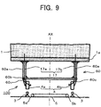
- the ATC antenna support device 20 is horizontally symmetrical with respect to the center line AX, and the ATC antenna support device 20 is constructed by components all made of non-magnetic metal materials, such as stainless steel and the like. In doing so, as illustrated in FIG.
- the rail guard 11 on the front end of the body 1 serves as a magnetic body between the underfloor frame 1a of the body 1 and the rails 3.
- a magnetic circuit 19 is formed by the underfloor frame 1a of the body 1, the rail guard 11, the rails 3, the wheels 10, the bogie frame 9, and the like.
- the ATC antenna support device 20 is constructed of non-magnetic metal materials, the AC magnetic fluxes 17a and 17b that flow through the ATC antenna support device 20 are rather weak, and thus the magnetic fluxes 17a and 17b that pass through the ATC antenna coils 4a and 4b are also rather weak. Thus, even if AC voltages are induced in the ATC antenna coils 4a and 4b by the magnetic fluxes 17a and 17b, the induced AC voltages do not exceed the threshold. This enables erroneous detection of ATC speed signals to be prevented.
- the non-magnetic metal materials for use may include aluminum, alloys thereof, and the like.
- the ATC antenna support device 20 is constructed by components all made of non-magnetic metal materials.
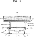
- the ATC antenna device 100 according to Embodiment 3, as illustrated in FIG. 15 includes an ATC antenna support device 30 instead of the ATC antenna support device 20.
- the ATC antenna support device 30 includes ATC antenna support bars 30a on the left and right, an ATC antenna support base 30b, and two ATC antenna attaching members 30c.
- the ATC antenna support device 30 is horizontally asymmetrical, and in this respect is the same as the ATC antenna support device 2 according to the previously described Embodiment 1. This enables erroneous detection of ATC speed signals to be prevented.
- the ATC antenna support device 30 is constructed by components made of non-magnetic metal materials. This further reduces the probability of erroneous detection of ATC speed signals.
- Embodiment 4 of the present disclosure is described. This embodiment does not form part of the invention.
- the ATC antenna support device 20 is constructed of non-magnetic metal materials.
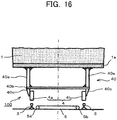
- the ATC antenna device 100 according to Embodiment 4 includes an ATC antenna support device 40 instead of the ATC antenna support device 20.
- the ATC antenna support device 40 includes ATC antenna support bars 40a on the left and right, an ATC antenna support base 40b, and two ATC antenna attaching members 40c.
- the ATC antenna support device 40 is in a horizontal symmetrical configuration with respect to the center line AX as illustrated in FIG. 16 , but the material of the ATC antenna support device 40 is a combination of reinforced plastic materials and non-magnetic metal materials. Examples of reinforced plastic that may be used include glass fiber reinforced plastic (GFRP), carbon fiber reinforced plastic (CFRP), and the like.
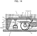
- the magnetic circuit 19 is formed as illustrated in FIG. 14 .
- the AC magnetic flux 17 that passes through the ATC antenna coils 4a and 4b is rather weak, and the AC voltages induced in the ATC antenna coils 4a and 4b by the AC magnetic flux 17 do not exceed the threshold, thus enabling prevention of erroneous detection of ATC speed signals.
- the ATC antenna support device 40 may be constructed solely of reinforced plastic, which can improve the strength of the ATC antenna support device 2 and even reduce the weight thereof.
- the ATC antenna support device 30 which is horizontally asymmetrical with respect to the center line, is constructed by components all made of non-magnetic metal materials.
- the ATC antenna device 100 according to Embodiment 5 includes an ATC antenna support device 50 instead of the ATC antenna support device 30.
- the ATC antenna support device 50 includes ATC antenna support bars 50a on the left and right, an ATC antenna support base 50b, and two ATC antenna attaching members 50c.
- the ATC antenna support device 50 is horizontally asymmetrical, and in this respect is the same as the ATC antenna support device 2 according to the previously described Embodiment 1. This enables erroneous detection of ATC speed signals to be prevented.
- the ATC antenna support device 50 is made of a combination of reinforced plastic materials and non-magnetic metal materials. This further reduces the probability of erroneous detection of ATC speed signals.
- the ATC antenna support device 50 may be constructed solely of reinforced plastic. Doing so can improve the strength of the ATC antenna support device 2 and even reduce the weight thereof.
- the ATC antenna support devices 2, 30, and 50 which support the paired ATC antenna coils 4a and 4b, are asymmetrical with respect to the center of the body 1, and the paired ATC antenna coils 4a and 4b are symmetrical with respect to the center line AX of the body 1.
- the AC magnetic flux 17, which occurs at the traction motor 7 and the traction motor cables 8, passes through the paired ATC antenna coils 4a and 4b in phase via the ATC antenna support device 2, 30, or 50.
- the ATC antenna support devices 20, 30, 40, and 50 are formed of non-magnetic metal materials or reinforced plastic or both. Accordingly, the AC magnetic flux 17 resulting from the traction motor current flowing through the ATC antenna coils 4a and 4b is substantially reduced, and this enables erroneous detection ATC command speeds to be prevented. Also, the use of reinforced plastic can improve the strength of the ATC antenna support devices 40 and 50 and even reduce the weight thereof.
- the present disclosure which is applied to rolling stock that perform ATC, is described as an example, but the present disclosure may also be applied to the automobile industry and general industries in the field of non-contact signal transmission utilizing magnetism.
Landscapes
- Engineering & Computer Science (AREA)
- Mechanical Engineering (AREA)
- Power Engineering (AREA)
- Transportation (AREA)
- Remote Sensing (AREA)
- Life Sciences & Earth Sciences (AREA)
- Sustainable Development (AREA)
- Sustainable Energy (AREA)
- Electric Propulsion And Braking For Vehicles (AREA)
- Train Traffic Observation, Control, And Security (AREA)
- Details Of Aerials (AREA)
Claims (4)
- Automatische Zugsteuerungs-, ATC, Antennenvorrichtung (100), die an einem Körper (1) eines Führungswagens bereitgestellt ist, um Signale von außen durch elektromagnetische Kopplung zu empfangen, wobei die ATC-Antennenvorrichtung (100) aufweist:ein Paar von ATC-Antennenspulen (4a, 4b), die symmetrisch in Bezug auf eine vertikale Mittellinie (AX) des Körper (1), wenn dieser in einer Fahrtrichtung des Körpers (1) betrachtet wird, angeordnet sind, wobei die gepaarten ATC-Antennenspulen (4a, 4b) in Reihe und in entgegengesetzten Phasen verbunden sind; undeine ATC-Antennenstützung (2, 30, 50), die dazu konfiguriert ist, an dem Körper (1) angebracht zu werden, um die gepaarten ATC-Antennenspulen (4a, 4b) zu stützen und dazu konfiguriert ist, asymmetrisch in Bezug auf die vertikale Mittellinie (AX) angeordnet zu werden;wobei die ATC-Antennenvorrichtung (100) dadurch gekennzeichnet ist:dass die ATC-Antennenstützung (2, 30, 50) zwei sich vertikal erstreckende ATC-Antennenstützleisten (2a) aufweist, die dazu konfiguriert sind, rechts und links der vertikalen Mittellinie (AX) in einem vorbestimmten Abstand zwischen sich angeordnet zu werden, wobei das obere Ende der zwei ATC-Antennenstützleisten (2a) dazu konfiguriert ist, an dem Unterabschnitt eines Unterbodenrahmens (1a) des Körpers (1) befestigt zu werden,dass die ATC-Antennenstützung (2, 30, 50) eine sich horizontal erstreckende ATC-Antennenstützbasis (2b) aufweist, die an beiden Unterenden der zwei ATC-Antennenstützleisten (2a) aufgehängt ist,und dass die ATC-Antennenstützung (2, 30, 50) ATC-Antennenanbringungselemente (2c) aufweist, von denen beide an dem Unterabschnitt der ATC-Antennenstützbasis (2b) angeordnet sind und in derselben Lateralrichtung orientiert sind, wobei die gepaarten ATC-Antennenspulen (4a, 4b) fest an den ATC-Antennenanbringungselementen (2c) angebracht sind, entweder beide auf der rechten Seite oder beide auf der linken Seite der ATC-Antennenanbringungselemente (2c).
- ATC-Antennenvorrichtung (100) nach Anspruch 1, dadurch gekennzeichnet, dass:
die ATC-Antennenstützung (2, 30, 50) aus einem nicht magnetischen Metallmaterial, einem verstärkten Kunststoff oder einer Kombination davon ausgebildet ist. - ATC-Signalempfangsvorrichtung (7, 13, 14, 15, 100), dadurch gekennzeichnet, dass sie aufweist:die ATC-Antennenvorrichtung (100) nach Anspruch 1; undeinen Empfänger (13) zum Empfangen eines Induktionsspannungssignals, das durch die ATC-Antennenvorrichtung (100) ausgegeben wird.
- Wagen (1, 100), der gekennzeichnet ist dadurch, dass er aufweist:die ATC-Antennenvorrichtung (100) nach Anspruch 1; undeinen Körper (1), der einen Boden aufweist, an dem die ATC-Antennenvorrichtung (100) angebracht ist.
Applications Claiming Priority (1)
| Application Number | Priority Date | Filing Date | Title |
|---|---|---|---|
| PCT/JP2014/063613 WO2015177911A1 (ja) | 2014-05-22 | 2014-05-22 | Atcアンテナ装置、atc信号伝送装置及び車両 |
Publications (3)
| Publication Number | Publication Date |
|---|---|
| EP3132965A1 EP3132965A1 (de) | 2017-02-22 |
| EP3132965A4 EP3132965A4 (de) | 2017-12-13 |
| EP3132965B1 true EP3132965B1 (de) | 2019-07-31 |
Family
ID=54553604
Family Applications (1)
| Application Number | Title | Priority Date | Filing Date |
|---|---|---|---|
| EP14892564.7A Active EP3132965B1 (de) | 2014-05-22 | 2014-05-22 | Atc-antennenvorrichtung, atc-signal-übertragungsvorrichtung und fahrzeug |
Country Status (4)
| Country | Link |
|---|---|
| US (1) | US10069197B2 (de) |
| EP (1) | EP3132965B1 (de) |
| JP (1) | JP6157731B2 (de) |
| WO (1) | WO2015177911A1 (de) |
Families Citing this family (1)
| Publication number | Priority date | Publication date | Assignee | Title |
|---|---|---|---|---|
| US10279823B2 (en) * | 2016-08-08 | 2019-05-07 | General Electric Company | System for controlling or monitoring a vehicle system along a route |
Family Cites Families (12)
| Publication number | Priority date | Publication date | Assignee | Title |
|---|---|---|---|---|
| US1655006A (en) * | 1926-07-29 | 1928-01-03 | Union Switch & Signal Co | Train-carried receiver for automatic train-control systems |
| US2662934A (en) * | 1949-02-08 | 1953-12-15 | Westinghouse Air Brake Co | Vacuum tube amplifier circuits for coded carrier current |
| US3493741A (en) * | 1968-03-26 | 1970-02-03 | Westinghouse Air Brake Co | Object stopping system |
| FR2434069A1 (fr) * | 1978-07-27 | 1980-03-21 | Silec Liaisons Elec | Dispositif de signalisation pour vehicules guides |
| JPS6076469A (ja) | 1983-09-29 | 1985-04-30 | 日本信号株式会社 | 自動列車制御装置 |
| JP3452269B2 (ja) * | 1993-07-22 | 2003-09-29 | 日本信号株式会社 | 車上受信装置 |
| JPH1059180A (ja) * | 1996-08-23 | 1998-03-03 | Nippon Signal Co Ltd:The | 軌道短絡検出装置 |
| JP2001138914A (ja) * | 1999-11-12 | 2001-05-22 | Kyosan Electric Mfg Co Ltd | 受電器 |
| JP3902929B2 (ja) | 2001-08-31 | 2007-04-11 | 三菱重工業株式会社 | 車上装置 |
| JP4958212B2 (ja) * | 2006-10-10 | 2012-06-20 | 日本信号株式会社 | 車両制御装置 |
| JP5583553B2 (ja) * | 2010-11-08 | 2014-09-03 | 川崎重工業株式会社 | 鉄道車両の台枠構造 |
| JP2014023189A (ja) * | 2012-07-12 | 2014-02-03 | Nippon Signal Co Ltd:The | 列車制御装置及び雑音低減方法 |
-
2014
- 2014-05-22 JP JP2016520880A patent/JP6157731B2/ja active Active
- 2014-05-22 EP EP14892564.7A patent/EP3132965B1/de active Active
- 2014-05-22 WO PCT/JP2014/063613 patent/WO2015177911A1/ja not_active Ceased
- 2014-05-22 US US15/127,270 patent/US10069197B2/en active Active
Non-Patent Citations (1)
| Title |
|---|
| None * |
Also Published As
| Publication number | Publication date |
|---|---|
| EP3132965A1 (de) | 2017-02-22 |
| JP6157731B2 (ja) | 2017-07-05 |
| EP3132965A4 (de) | 2017-12-13 |
| US20170110791A1 (en) | 2017-04-20 |
| WO2015177911A1 (ja) | 2015-11-26 |
| US10069197B2 (en) | 2018-09-04 |
| JPWO2015177911A1 (ja) | 2017-04-20 |
Similar Documents
| Publication | Publication Date | Title |
|---|---|---|
| CN103826961B (zh) | 列车控制系统的地面装置 | |
| US20130119978A1 (en) | Inductive sensor device and inductive proximity sensor with an inductive sensor device | |
| KR101944164B1 (ko) | 유도 차량의 정확한 복선을 제어하기 위한 방법 및 디바이스 | |
| EP3172107B1 (de) | System und verfahren zur lokalisierung des mittelpunktes von mit balisen ausgestatteten geführten fahrzeugrouten | |
| GB2478010A (en) | Radio frequency identification for detecting location of a train or tram. | |
| EP3132965B1 (de) | Atc-antennenvorrichtung, atc-signal-übertragungsvorrichtung und fahrzeug | |
| KR101029516B1 (ko) | 궤도차량 위치 검지 시스템 | |
| CN103476661B (zh) | 运行轨道车辆的方法及线路侧的装置和具有该装置的设备 | |
| KR20150102403A (ko) | 마그네틱 바와 rfid 태그를 이용한 자기부상 열차용 열차 위치 검출장치 | |
| KR101698057B1 (ko) | 차륜검지센서의 탈락을 검지할 수 있는 차축카운터시스템 | |
| JP6302747B2 (ja) | 車両制御システム | |
| JP2015033989A (ja) | 列車検知装置 | |
| JP6254326B1 (ja) | 脱輪防止機能を備える磁気式安全運転支援システム | |
| JP5545787B1 (ja) | 地上子 | |
| KR102461688B1 (ko) | 검지 시스템 | |
| JP2012058792A (ja) | 搬送装置 | |
| US6527230B1 (en) | Track receiver | |
| KR101029271B1 (ko) | 선로 전환기 제어 시스템 | |
| JPH036521B2 (de) | ||
| JP4907913B2 (ja) | 鉄道車両位置検知装置 | |
| US3550077A (en) | Vehicle guidance system | |
| JPWO2016079837A1 (ja) | 非接触給電システム、車両、及び非接触給電方法 | |
| JP2024034509A (ja) | 列車位置検知装置および列車位置検知方法 | |
| JP2913627B1 (ja) | 受電器 | |
| JP2013159213A (ja) | 踏切制御装置 |
Legal Events
| Date | Code | Title | Description |
|---|---|---|---|
| STAA | Information on the status of an ep patent application or granted ep patent |
Free format text: STATUS: THE INTERNATIONAL PUBLICATION HAS BEEN MADE |
|
| PUAI | Public reference made under article 153(3) epc to a published international application that has entered the european phase |
Free format text: ORIGINAL CODE: 0009012 |
|
| STAA | Information on the status of an ep patent application or granted ep patent |
Free format text: STATUS: REQUEST FOR EXAMINATION WAS MADE |
|
| 17P | Request for examination filed |
Effective date: 20161114 |
|
| AK | Designated contracting states |
Kind code of ref document: A1 Designated state(s): AL AT BE BG CH CY CZ DE DK EE ES FI FR GB GR HR HU IE IS IT LI LT LU LV MC MK MT NL NO PL PT RO RS SE SI SK SM TR |
|
| AX | Request for extension of the european patent |
Extension state: BA ME |
|
| DAX | Request for extension of the european patent (deleted) | ||
| A4 | Supplementary search report drawn up and despatched |
Effective date: 20171115 |
|
| RIC1 | Information provided on ipc code assigned before grant |
Ipc: B61L 23/16 20060101ALI20171109BHEP Ipc: H01Q 7/00 20060101ALI20171109BHEP Ipc: B60L 3/08 20060101AFI20171109BHEP Ipc: B60L 3/00 20060101ALI20171109BHEP Ipc: B61L 3/12 20060101ALI20171109BHEP Ipc: H01Q 1/32 20060101ALI20171109BHEP Ipc: B60L 15/40 20060101ALI20171109BHEP |
|
| REG | Reference to a national code |
Ref country code: DE Ref legal event code: R079 Ref document number: 602014051081 Country of ref document: DE Free format text: PREVIOUS MAIN CLASS: B60L0003080000 Ipc: H01Q0001320000 |
|
| RIC1 | Information provided on ipc code assigned before grant |
Ipc: H01Q 1/32 20060101AFI20181219BHEP Ipc: B61L 3/00 20060101ALI20181219BHEP Ipc: H01Q 7/00 20060101ALI20181219BHEP Ipc: B61L 27/00 20060101ALI20181219BHEP Ipc: B61L 3/12 20060101ALI20181219BHEP |
|
| GRAP | Despatch of communication of intention to grant a patent |
Free format text: ORIGINAL CODE: EPIDOSNIGR1 |
|
| STAA | Information on the status of an ep patent application or granted ep patent |
Free format text: STATUS: GRANT OF PATENT IS INTENDED |
|
| INTG | Intention to grant announced |
Effective date: 20190215 |
|
| GRAS | Grant fee paid |
Free format text: ORIGINAL CODE: EPIDOSNIGR3 |
|
| GRAA | (expected) grant |
Free format text: ORIGINAL CODE: 0009210 |
|
| STAA | Information on the status of an ep patent application or granted ep patent |
Free format text: STATUS: THE PATENT HAS BEEN GRANTED |
|
| AK | Designated contracting states |
Kind code of ref document: B1 Designated state(s): AL AT BE BG CH CY CZ DE DK EE ES FI FR GB GR HR HU IE IS IT LI LT LU LV MC MK MT NL NO PL PT RO RS SE SI SK SM TR |
|
| REG | Reference to a national code |
Ref country code: CH Ref legal event code: EP Ref country code: GB Ref legal event code: FG4D |
|
| REG | Reference to a national code |
Ref country code: DE Ref legal event code: R096 Ref document number: 602014051081 Country of ref document: DE |
|
| REG | Reference to a national code |
Ref country code: AT Ref legal event code: REF Ref document number: 1161918 Country of ref document: AT Kind code of ref document: T Effective date: 20190815 |
|
| REG | Reference to a national code |
Ref country code: IE Ref legal event code: FG4D |
|
| REG | Reference to a national code |
Ref country code: NL Ref legal event code: MP Effective date: 20190731 |
|
| REG | Reference to a national code |
Ref country code: LT Ref legal event code: MG4D |
|
| REG | Reference to a national code |
Ref country code: AT Ref legal event code: MK05 Ref document number: 1161918 Country of ref document: AT Kind code of ref document: T Effective date: 20190731 |
|
| PG25 | Lapsed in a contracting state [announced via postgrant information from national office to epo] |
Ref country code: FI Free format text: LAPSE BECAUSE OF FAILURE TO SUBMIT A TRANSLATION OF THE DESCRIPTION OR TO PAY THE FEE WITHIN THE PRESCRIBED TIME-LIMIT Effective date: 20190731 Ref country code: SE Free format text: LAPSE BECAUSE OF FAILURE TO SUBMIT A TRANSLATION OF THE DESCRIPTION OR TO PAY THE FEE WITHIN THE PRESCRIBED TIME-LIMIT Effective date: 20190731 Ref country code: BG Free format text: LAPSE BECAUSE OF FAILURE TO SUBMIT A TRANSLATION OF THE DESCRIPTION OR TO PAY THE FEE WITHIN THE PRESCRIBED TIME-LIMIT Effective date: 20191031 Ref country code: AT Free format text: LAPSE BECAUSE OF FAILURE TO SUBMIT A TRANSLATION OF THE DESCRIPTION OR TO PAY THE FEE WITHIN THE PRESCRIBED TIME-LIMIT Effective date: 20190731 Ref country code: NL Free format text: LAPSE BECAUSE OF FAILURE TO SUBMIT A TRANSLATION OF THE DESCRIPTION OR TO PAY THE FEE WITHIN THE PRESCRIBED TIME-LIMIT Effective date: 20190731 Ref country code: HR Free format text: LAPSE BECAUSE OF FAILURE TO SUBMIT A TRANSLATION OF THE DESCRIPTION OR TO PAY THE FEE WITHIN THE PRESCRIBED TIME-LIMIT Effective date: 20190731 Ref country code: NO Free format text: LAPSE BECAUSE OF FAILURE TO SUBMIT A TRANSLATION OF THE DESCRIPTION OR TO PAY THE FEE WITHIN THE PRESCRIBED TIME-LIMIT Effective date: 20191031 Ref country code: LT Free format text: LAPSE BECAUSE OF FAILURE TO SUBMIT A TRANSLATION OF THE DESCRIPTION OR TO PAY THE FEE WITHIN THE PRESCRIBED TIME-LIMIT Effective date: 20190731 Ref country code: PT Free format text: LAPSE BECAUSE OF FAILURE TO SUBMIT A TRANSLATION OF THE DESCRIPTION OR TO PAY THE FEE WITHIN THE PRESCRIBED TIME-LIMIT Effective date: 20191202 |
|
| PG25 | Lapsed in a contracting state [announced via postgrant information from national office to epo] |
Ref country code: IS Free format text: LAPSE BECAUSE OF FAILURE TO SUBMIT A TRANSLATION OF THE DESCRIPTION OR TO PAY THE FEE WITHIN THE PRESCRIBED TIME-LIMIT Effective date: 20191130 Ref country code: GR Free format text: LAPSE BECAUSE OF FAILURE TO SUBMIT A TRANSLATION OF THE DESCRIPTION OR TO PAY THE FEE WITHIN THE PRESCRIBED TIME-LIMIT Effective date: 20191101 Ref country code: LV Free format text: LAPSE BECAUSE OF FAILURE TO SUBMIT A TRANSLATION OF THE DESCRIPTION OR TO PAY THE FEE WITHIN THE PRESCRIBED TIME-LIMIT Effective date: 20190731 Ref country code: ES Free format text: LAPSE BECAUSE OF FAILURE TO SUBMIT A TRANSLATION OF THE DESCRIPTION OR TO PAY THE FEE WITHIN THE PRESCRIBED TIME-LIMIT Effective date: 20190731 Ref country code: AL Free format text: LAPSE BECAUSE OF FAILURE TO SUBMIT A TRANSLATION OF THE DESCRIPTION OR TO PAY THE FEE WITHIN THE PRESCRIBED TIME-LIMIT Effective date: 20190731 Ref country code: RS Free format text: LAPSE BECAUSE OF FAILURE TO SUBMIT A TRANSLATION OF THE DESCRIPTION OR TO PAY THE FEE WITHIN THE PRESCRIBED TIME-LIMIT Effective date: 20190731 |
|
| PG25 | Lapsed in a contracting state [announced via postgrant information from national office to epo] |
Ref country code: TR Free format text: LAPSE BECAUSE OF FAILURE TO SUBMIT A TRANSLATION OF THE DESCRIPTION OR TO PAY THE FEE WITHIN THE PRESCRIBED TIME-LIMIT Effective date: 20190731 |
|
| PG25 | Lapsed in a contracting state [announced via postgrant information from national office to epo] |
Ref country code: RO Free format text: LAPSE BECAUSE OF FAILURE TO SUBMIT A TRANSLATION OF THE DESCRIPTION OR TO PAY THE FEE WITHIN THE PRESCRIBED TIME-LIMIT Effective date: 20190731 Ref country code: PL Free format text: LAPSE BECAUSE OF FAILURE TO SUBMIT A TRANSLATION OF THE DESCRIPTION OR TO PAY THE FEE WITHIN THE PRESCRIBED TIME-LIMIT Effective date: 20190731 Ref country code: EE Free format text: LAPSE BECAUSE OF FAILURE TO SUBMIT A TRANSLATION OF THE DESCRIPTION OR TO PAY THE FEE WITHIN THE PRESCRIBED TIME-LIMIT Effective date: 20190731 Ref country code: IT Free format text: LAPSE BECAUSE OF FAILURE TO SUBMIT A TRANSLATION OF THE DESCRIPTION OR TO PAY THE FEE WITHIN THE PRESCRIBED TIME-LIMIT Effective date: 20190731 Ref country code: DK Free format text: LAPSE BECAUSE OF FAILURE TO SUBMIT A TRANSLATION OF THE DESCRIPTION OR TO PAY THE FEE WITHIN THE PRESCRIBED TIME-LIMIT Effective date: 20190731 |
|
| PG25 | Lapsed in a contracting state [announced via postgrant information from national office to epo] |
Ref country code: SK Free format text: LAPSE BECAUSE OF FAILURE TO SUBMIT A TRANSLATION OF THE DESCRIPTION OR TO PAY THE FEE WITHIN THE PRESCRIBED TIME-LIMIT Effective date: 20190731 Ref country code: CZ Free format text: LAPSE BECAUSE OF FAILURE TO SUBMIT A TRANSLATION OF THE DESCRIPTION OR TO PAY THE FEE WITHIN THE PRESCRIBED TIME-LIMIT Effective date: 20190731 Ref country code: SM Free format text: LAPSE BECAUSE OF FAILURE TO SUBMIT A TRANSLATION OF THE DESCRIPTION OR TO PAY THE FEE WITHIN THE PRESCRIBED TIME-LIMIT Effective date: 20190731 Ref country code: IS Free format text: LAPSE BECAUSE OF FAILURE TO SUBMIT A TRANSLATION OF THE DESCRIPTION OR TO PAY THE FEE WITHIN THE PRESCRIBED TIME-LIMIT Effective date: 20200224 |
|
| REG | Reference to a national code |
Ref country code: DE Ref legal event code: R097 Ref document number: 602014051081 Country of ref document: DE |
|
| PLBE | No opposition filed within time limit |
Free format text: ORIGINAL CODE: 0009261 |
|
| STAA | Information on the status of an ep patent application or granted ep patent |
Free format text: STATUS: NO OPPOSITION FILED WITHIN TIME LIMIT |
|
| PG2D | Information on lapse in contracting state deleted |
Ref country code: IS |
|
| PG25 | Lapsed in a contracting state [announced via postgrant information from national office to epo] |
Ref country code: IS Free format text: LAPSE BECAUSE OF FAILURE TO SUBMIT A TRANSLATION OF THE DESCRIPTION OR TO PAY THE FEE WITHIN THE PRESCRIBED TIME-LIMIT Effective date: 20191030 |
|
| 26N | No opposition filed |
Effective date: 20200603 |
|
| PG25 | Lapsed in a contracting state [announced via postgrant information from national office to epo] |
Ref country code: SI Free format text: LAPSE BECAUSE OF FAILURE TO SUBMIT A TRANSLATION OF THE DESCRIPTION OR TO PAY THE FEE WITHIN THE PRESCRIBED TIME-LIMIT Effective date: 20190731 |
|
| PG25 | Lapsed in a contracting state [announced via postgrant information from national office to epo] |
Ref country code: LI Free format text: LAPSE BECAUSE OF NON-PAYMENT OF DUE FEES Effective date: 20200531 Ref country code: CH Free format text: LAPSE BECAUSE OF NON-PAYMENT OF DUE FEES Effective date: 20200531 Ref country code: MC Free format text: LAPSE BECAUSE OF FAILURE TO SUBMIT A TRANSLATION OF THE DESCRIPTION OR TO PAY THE FEE WITHIN THE PRESCRIBED TIME-LIMIT Effective date: 20190731 |
|
| REG | Reference to a national code |
Ref country code: BE Ref legal event code: MM Effective date: 20200531 |
|
| GBPC | Gb: european patent ceased through non-payment of renewal fee |
Effective date: 20200522 |
|
| PG25 | Lapsed in a contracting state [announced via postgrant information from national office to epo] |
Ref country code: LU Free format text: LAPSE BECAUSE OF NON-PAYMENT OF DUE FEES Effective date: 20200522 |
|
| PG25 | Lapsed in a contracting state [announced via postgrant information from national office to epo] |
Ref country code: IE Free format text: LAPSE BECAUSE OF NON-PAYMENT OF DUE FEES Effective date: 20200522 Ref country code: GB Free format text: LAPSE BECAUSE OF NON-PAYMENT OF DUE FEES Effective date: 20200522 Ref country code: FR Free format text: LAPSE BECAUSE OF NON-PAYMENT OF DUE FEES Effective date: 20200531 |
|
| PG25 | Lapsed in a contracting state [announced via postgrant information from national office to epo] |
Ref country code: BE Free format text: LAPSE BECAUSE OF NON-PAYMENT OF DUE FEES Effective date: 20200531 |
|
| PG25 | Lapsed in a contracting state [announced via postgrant information from national office to epo] |
Ref country code: MT Free format text: LAPSE BECAUSE OF FAILURE TO SUBMIT A TRANSLATION OF THE DESCRIPTION OR TO PAY THE FEE WITHIN THE PRESCRIBED TIME-LIMIT Effective date: 20190731 Ref country code: CY Free format text: LAPSE BECAUSE OF FAILURE TO SUBMIT A TRANSLATION OF THE DESCRIPTION OR TO PAY THE FEE WITHIN THE PRESCRIBED TIME-LIMIT Effective date: 20190731 |
|
| PG25 | Lapsed in a contracting state [announced via postgrant information from national office to epo] |
Ref country code: MK Free format text: LAPSE BECAUSE OF FAILURE TO SUBMIT A TRANSLATION OF THE DESCRIPTION OR TO PAY THE FEE WITHIN THE PRESCRIBED TIME-LIMIT Effective date: 20190731 |
|
| REG | Reference to a national code |
Ref country code: DE Ref legal event code: R084 Ref document number: 602014051081 Country of ref document: DE |
|
| P01 | Opt-out of the competence of the unified patent court (upc) registered |
Effective date: 20230512 |
|
| PGFP | Annual fee paid to national office [announced via postgrant information from national office to epo] |
Ref country code: DE Payment date: 20250402 Year of fee payment: 12 |