EP3132972B1 - Composant d'habillage pour véhicule - Google Patents
Composant d'habillage pour véhicule Download PDFInfo
- Publication number
- EP3132972B1 EP3132972B1 EP15181725.1A EP15181725A EP3132972B1 EP 3132972 B1 EP3132972 B1 EP 3132972B1 EP 15181725 A EP15181725 A EP 15181725A EP 3132972 B1 EP3132972 B1 EP 3132972B1
- Authority
- EP
- European Patent Office
- Prior art keywords
- light
- vehicle
- light guide
- light source
- trim component
- Prior art date
- Legal status (The legal status is an assumption and is not a legal conclusion. Google has not performed a legal analysis and makes no representation as to the accuracy of the status listed.)
- Active
Links
Images


Classifications
-
- B—PERFORMING OPERATIONS; TRANSPORTING
- B60—VEHICLES IN GENERAL
- B60Q—ARRANGEMENT OF SIGNALLING OR LIGHTING DEVICES, THE MOUNTING OR SUPPORTING THEREOF OR CIRCUITS THEREFOR, FOR VEHICLES IN GENERAL
- B60Q1/00—Arrangement of optical signalling or lighting devices, the mounting or supporting thereof or circuits therefor
- B60Q1/26—Arrangement of optical signalling or lighting devices, the mounting or supporting thereof or circuits therefor the devices being primarily intended to indicate the vehicle, or parts thereof, or to give signals, to other traffic
- B60Q1/2619—Arrangement of optical signalling or lighting devices, the mounting or supporting thereof or circuits therefor the devices being primarily intended to indicate the vehicle, or parts thereof, or to give signals, to other traffic built in the vehicle body
-
- B—PERFORMING OPERATIONS; TRANSPORTING
- B60—VEHICLES IN GENERAL
- B60Q—ARRANGEMENT OF SIGNALLING OR LIGHTING DEVICES, THE MOUNTING OR SUPPORTING THEREOF OR CIRCUITS THEREFOR, FOR VEHICLES IN GENERAL
- B60Q1/00—Arrangement of optical signalling or lighting devices, the mounting or supporting thereof or circuits therefor
- B60Q1/02—Arrangement of optical signalling or lighting devices, the mounting or supporting thereof or circuits therefor the devices being primarily intended to illuminate the way ahead or to illuminate other areas of way or environments
- B60Q1/24—Arrangement of optical signalling or lighting devices, the mounting or supporting thereof or circuits therefor the devices being primarily intended to illuminate the way ahead or to illuminate other areas of way or environments for lighting other areas than only the way ahead
- B60Q1/247—Arrangement of optical signalling or lighting devices, the mounting or supporting thereof or circuits therefor the devices being primarily intended to illuminate the way ahead or to illuminate other areas of way or environments for lighting other areas than only the way ahead for illuminating the close surroundings of the vehicle, e.g. to facilitate entry or exit
-
- B—PERFORMING OPERATIONS; TRANSPORTING
- B60—VEHICLES IN GENERAL
- B60Q—ARRANGEMENT OF SIGNALLING OR LIGHTING DEVICES, THE MOUNTING OR SUPPORTING THEREOF OR CIRCUITS THEREFOR, FOR VEHICLES IN GENERAL
- B60Q1/00—Arrangement of optical signalling or lighting devices, the mounting or supporting thereof or circuits therefor
- B60Q1/26—Arrangement of optical signalling or lighting devices, the mounting or supporting thereof or circuits therefor the devices being primarily intended to indicate the vehicle, or parts thereof, or to give signals, to other traffic
- B60Q1/32—Arrangement of optical signalling or lighting devices, the mounting or supporting thereof or circuits therefor the devices being primarily intended to indicate the vehicle, or parts thereof, or to give signals, to other traffic for indicating vehicle sides, e.g. clearance lights
- B60Q1/323—Arrangement of optical signalling or lighting devices, the mounting or supporting thereof or circuits therefor the devices being primarily intended to indicate the vehicle, or parts thereof, or to give signals, to other traffic for indicating vehicle sides, e.g. clearance lights on or for doors
-
- B—PERFORMING OPERATIONS; TRANSPORTING
- B60—VEHICLES IN GENERAL
- B60Q—ARRANGEMENT OF SIGNALLING OR LIGHTING DEVICES, THE MOUNTING OR SUPPORTING THEREOF OR CIRCUITS THEREFOR, FOR VEHICLES IN GENERAL
- B60Q3/00—Arrangement of lighting devices for vehicle interiors; Lighting devices specially adapted for vehicle interiors
- B60Q3/50—Mounting arrangements
- B60Q3/54—Lighting devices embedded in interior trim, e.g. in roof liners
-
- B—PERFORMING OPERATIONS; TRANSPORTING
- B60—VEHICLES IN GENERAL
- B60Q—ARRANGEMENT OF SIGNALLING OR LIGHTING DEVICES, THE MOUNTING OR SUPPORTING THEREOF OR CIRCUITS THEREFOR, FOR VEHICLES IN GENERAL
- B60Q2400/00—Special features or arrangements of exterior signal lamps for vehicles
- B60Q2400/40—Welcome lights, i.e. specific or existing exterior lamps to assist leaving or approaching the vehicle
-
- B—PERFORMING OPERATIONS; TRANSPORTING
- B60—VEHICLES IN GENERAL
- B60Q—ARRANGEMENT OF SIGNALLING OR LIGHTING DEVICES, THE MOUNTING OR SUPPORTING THEREOF OR CIRCUITS THEREFOR, FOR VEHICLES IN GENERAL
- B60Q3/00—Arrangement of lighting devices for vehicle interiors; Lighting devices specially adapted for vehicle interiors
- B60Q3/20—Arrangement of lighting devices for vehicle interiors; Lighting devices specially adapted for vehicle interiors for lighting specific fittings of passenger or driving compartments; mounted on specific fittings of passenger or driving compartments
- B60Q3/217—Doors, e.g. door sills; Steps
-
- B—PERFORMING OPERATIONS; TRANSPORTING
- B60—VEHICLES IN GENERAL
- B60Q—ARRANGEMENT OF SIGNALLING OR LIGHTING DEVICES, THE MOUNTING OR SUPPORTING THEREOF OR CIRCUITS THEREFOR, FOR VEHICLES IN GENERAL
- B60Q3/00—Arrangement of lighting devices for vehicle interiors; Lighting devices specially adapted for vehicle interiors
- B60Q3/60—Arrangement of lighting devices for vehicle interiors; Lighting devices specially adapted for vehicle interiors characterised by optical aspects
- B60Q3/62—Arrangement of lighting devices for vehicle interiors; Lighting devices specially adapted for vehicle interiors characterised by optical aspects using light guides
- B60Q3/64—Arrangement of lighting devices for vehicle interiors; Lighting devices specially adapted for vehicle interiors characterised by optical aspects using light guides for a single lighting device
Definitions
- the present invention relates to a trim component for a vehicle.
- the invention also relates to a lighting device for the trim component and a vehicle with such a trim component.
- Paneling components of vehicles include, in particular, side skirts and bumpers, which, in addition to covering the vehicle, also serve to protect the vehicle body in the event of impacts and stone chips, and, in particular in off-road vehicles and SUVs, also serve as running boards.
- approach lighting In addition to the usual lighting such as high and tail lights, indicators and brake lights, modern automobiles often also have surround or approach lighting, which is located, for example, in the side mirrors and/or the doors and/or the door openers and can be used to illuminate the immediate area around the vehicle when the vehicle is parked and users want to get in or out.
- approach lighting may only be activated when the vehicle is stationary. As soon as the vehicle is moved, the approach lighting must be switched off. It makes it easier for vehicle users to open the door in the dark because the door handle is clearly visible.
- the approach lighting makes obstacles on the ground in the immediate vicinity of the door visible, such as stones or puddles.
- a disadvantage of such apron lighting installed in the side mirrors and/or in the door openers or doors is that the illuminated apron depends on the position of the door. So when the door is opened and the user wants to get into the vehicle, the floor between the opened door and the rest of the bodywork are not illuminated, which can lead to the user no longer seeing previously illuminated obstacles when getting in after opening the door and, for example, stepping into a puddle.
- the US 8 235 568 B2 proposes to mount a number of LEDs on the side sills in order to illuminate the immediate area around the vehicle regardless of the position of the door.
- the disadvantage of this arrangement is that the LEDs only illuminate the area around the vehicle in specific spots. Since the LEDs protrude at least partially beyond the side panel, there is also a risk that they will be damaged or even destroyed by stone chips or other impacts. In addition, the LEDs protruding beyond the side panel create a visually disadvantageous appearance.
- the US 9 162 614 B1 , the DE 11 2013 005 176 T5 , the DE 10 2008 056 985 A1 and the DE 100 55 561 A1 show various lighting devices for motor vehicles, with which the surroundings of the vehicle can be illuminated.
- the US 2002/0030997 A1 shows a lighting device for ships, which can also be used for motor vehicles. What they all have in common is that uniform illumination of the area surrounding the vehicle, regardless of the position of the vehicle door, is either impossible or only possible with great effort.
- the DE 20 2004 008 681 U1 and the EP 2 028 046 A1 show illuminated decorative elements of vehicles that can be installed in particular on the door sill of a vehicle.
- the US 2004/0130883 A1 , the US 2003/0169384 A1 , the US 2002/0054488 A1 and the DE 697 35 125 T2 show lighting devices used for LCDs.
- the US 2009/0003002 A1 shows a flat lighting device.
- the object of the present invention is therefore to provide a panel component with which the surroundings of a vehicle can be evenly illuminated regardless of the position of the door, whereby the risk of damage or destruction during operation of the vehicle is to be largely reduced.
- the trim component for a vehicle comprises a wall which delimits an interior of the trim component, one or more through openings which penetrate the wall, and a lighting device arranged in the interior of the trim component, which can be connected to a light source and has one or more light guides which are arranged in relation to the through openings such that light emitted by the light guide can pass through the through openings.
- the through openings have an extension which runs essentially parallel to a longitudinal axis of the light guide, wherein the extension increases with increasing distance of the through openings from the light source.
- two adjacent through openings are arranged at a distance from each other that runs parallel to the light guide, the distance decreasing with increasing distance of the through openings from the light source.
- the lighting device can also comprise coupling elements with which the light from the light source can be coupled into the light guides.
- the lighting device can comprise brackets with which the light guide can be attached to the cladding component.
- the light guides can be made of PMMA (polymethyl methacrylate) or PC (polycarbonate) or can comprise these materials. When using these materials, the light guides are rigid, but can also be flexible, for example by using PU (polyurethane) or glass fibers.
- the light guides guide the light from the light source, which can be arranged away from the lighting device and thus does not have to be part of the lighting device in the sense of the present invention, to the point at which the light is required.
- the solution shown makes it possible according to the invention to arrange the light source in such a way that it is largely protected from external influences. This improves the reliability of the light source and consequently of the apron lighting.
- the use of light guides makes it possible to arrange the through-openings flexibly in the panel component and to choose their dimensions flexibly. This makes it possible to achieve very uniform illumination of the area surrounding the vehicle, so that the risk of the user noticing objects in the immediate vicinity that are not or only insufficiently illuminated is reduced.
- the light guides are located inside the panel component, which protects them from external influences. Even if, for example, a stone were to pass through the opening, the surface of the light guide would be damaged, but this usually results in slightly uneven illumination in certain areas, but does not affect the functionality of the apron lighting.
- the light guide has decoupling sections, particularly in the area of the through openings, in which the light can exit the light guide.
- the decoupling sections can be arranged as desired within the light guide, so that light is only coupled out where the through openings are located.
- the light guides are usually tubular or hose-shaped, with the light being guided from one end of the light guide, which is connected to the light source, to the free end where it exits the light guide. Consequently, a light guide must be laid at each through opening, which results in a relatively high assembly effort.
- the decoupling sections make it possible to couple light out of the light guides in a radial direction. This makes it possible to use just one light guide and guide it along the through openings, which is particularly simple from a manufacturing point of view. Because light is only coupled out radially from the light guide where there is a through opening, the loss of illuminance with increasing distance from the light source is reduced to a minimum. This also makes it possible to make the illumination of the immediate surroundings of the vehicle as uniform as possible
- the coupling-out sections have a number of notches or bulges, the number of notches or bulges per coupling-out section increasing with increasing distance of the coupling-out sections from the light source.
- the notches or bulges which are formed on the surface of the light guide and preferably run approximately perpendicular to the longitudinal axis of the light guide, cause diffraction and refraction effects, which lead to a radial coupling-out of the light from the light guide via the section of the surface that is opposite the notches.
- the illuminance that the light guide can still provide decreases. Consequently, the illuminance provided by a through-opening decreases with increasing distance from the light source for a constant number of notches. However, if the number of notches per coupling-out section is increased, the decrease in illuminance can be compensated or at least reduced. The illuminance provided per passage opening therefore remains the same or almost the same, which means that the area around the vehicle can be illuminated very evenly.
- the through-openings have an extension that runs essentially parallel to a longitudinal axis of the light guide, the extension increasing with increasing distance of the through-openings from the light source.
- the number of notches can remain the same over the entire length of the light guide.
- the invention provides that the distance decreases with increasing distance between the through openings and the light source. This measure can also compensate for the decrease in illuminance described above with increasing distance from the light source. This again results in more uniform illumination of the immediate surroundings of the vehicle.
- the light source can be arranged in the trim component.
- the use of light guides makes it possible to arrange the light source at a distance from the location where the light is required. Consequently, it is possible to arrange the light source inside the trim component where it is protected from external influences.
- arranging the light source in the trim component reduces the length of the required light guides and thus the weight and material costs, and also simplifies the installation of the trim component on the vehicle. Only the Light source must be connected to a suitably designed power supply of the vehicle, while the light guide(s) do not have to be connected to a light source arranged in the vehicle.
- the light source comprises one or in particular two LED boards.
- the LED board should comprise at least one LED and provide the infrastructure so that the LED can emit light.
- LEDs are characterized by a high light output with low heat generation. As a result, they convert electrical energy into light energy much more efficiently.
- they can be built more compactly, so that the required installation space can be significantly reduced compared to a light source that has a number of light bulbs.
- LED boards have a longer service life. When using two LED boards, light can be coupled in from both ends of the light guide, which increases the illuminance and overall achieves more uniform lighting of the area around the vehicle.
- the transparent layer can be made of PMMA (polymethyl methacrylate), PC (polycarbonate) or glass or can include these components.
- the transparent layer can be made of another suitable translucent material. This prevents dust, stones and other particles as well as moisture from penetrating the cladding component, which also prevents the light source and/or the light guide from becoming dirty and/or damaged.
- the through-openings and/or the lighting device and/or the light source can be arranged on a separate wall section that can be connected to the wall.
- the cladding components have a very angled and curved structure, which makes the assembly of the light guide and/or the light source and the production of the through-openings more difficult.
- the available working space when attaching the light guide(s) and/or the light source can be increased and the complexity of the assembly reduced, which is particularly the case when the separate wall section is flat or largely flat.
- the through-openings can be manufactured particularly easily with flat wall sections, for example by punching, injection molding, milling or lasering. It is also possible to have the separate wall section manufactured by a supplier and delivered to the assembly line in a fully assembled state. Of course, the separate wall section can also be connected to the cladding component by the supplier itself and delivered to the assembly line as a unit.
- a further aspect of the invention relates to a lighting device for a cladding component according to one of the previously described embodiments, which can be connected to a light source and has one or more light guides which are arranged in relation to the through-openings in such a way that light emitted by the light guide can pass through the through-openings.
- the technical effects and Advantages that can be achieved with this lighting device correspond to those that have been discussed for the corresponding embodiments of the panel components.
- the panel components according to the invention it is possible to evenly illuminate the surroundings of a vehicle regardless of the position of the door or doors, whereby the probability of destruction or damage to the area lighting during operation of the vehicle is greatly reduced.
- the invention also relates to a vehicle which comprises a panel component and/or a lighting device according to one of the previously presented embodiments.
- a vehicle which comprises a panel component and/or a lighting device according to one of the previously presented embodiments.
- the technical effects and advantages which can be achieved with this vehicle correspond to those which have been discussed for the corresponding embodiments of the panel components.
- the panel component according to the invention it is possible to evenly illuminate the surroundings of a vehicle regardless of the position of the door or doors, whereby the probability of destruction or damage to the area lighting during operation of the vehicle is greatly reduced.
- the panel component can be mounted on the vehicle in such a way that the light penetrating the openings is emitted towards the ground when the vehicle is used as intended. Due to country-specific safety regulations, it is not permitted in some countries to emit white light from the side of a vehicle. Often only orange light may be emitted from the side. However, orange light has the disadvantage that it does not affect the areas it illuminates. Sections are not particularly clearly illuminated. Because the invention makes it possible to only allow the light penetrating the passage openings to radiate towards the ground, white light can be used, which means that the area around the vehicle is particularly clearly illuminated. In addition, the passage openings are normally not visible to the user, which is advantageous from an aesthetic point of view. Since users do not normally look directly at the passage openings, they are not blinded by the light emerging.
- trim component is a side panel, a running board or a bumper of the vehicle.
- trim components do not change their position relative to the vehicle, unlike doors.
- the area around the vehicle is illuminated regardless of the position of the doors or tailgates. This reduces the risk that the user of the vehicle will come into contact with an object after opening the door, despite the initial illumination of the area around the vehicle, and thus become dirty or injured.
- FIG 1a is a first embodiment of a cladding component 10 1 according to the invention based on a plan view and in Figure 1b based on a cross-section along the Figure 1a
- the cladding component 10 1 comprises a wall 12 which, in relation to the section plane AA defined in Figure 1b selected view has a substantially horizontally extending section 14 which gradually changes into a substantially vertically extending section 16.
- the wall 12 separates an interior 18 of the cladding component 10 1 from an exterior 20.
- the cladding component 10 1 has a Through opening 22 which completely penetrates the wall 12 and has the shape of an elongated hole.
- the through opening 22 is closed with a transparent layer 24.
- the cladding component 10 1 comprises a lighting device 26, which has an essentially tubular light guide 27, which is rigid in the example shown.
- the lighting device 26 comprises fastening means (not shown) with which the light guide 27 is fastened to the cladding component 10 1 in such a way that it runs slightly above an inner lateral edge 29 of the through-opening 22.
- the light guide 27 has a decoupling section 28, which is implemented by a number of notches 30, which are located on a surface of the light guide 27. Not shown is the case where the decoupling section 28 has a number of bulges, which have the same effect as the notches 30.
- the decoupling section 28 it is possible to direct light, which comes from a light source (not shown here) (cf. Figures 3 and 4 ) coupled into the light guide 27 to exit radially from the light guide 27.
- the arrangement and orientation of the notches 30 determine over which surface and at which angle the light exits radially from the light guide 27.
- the main exit direction of the light from the light guide 27 is marked with the arrow P. It can be seen that the light exits from the light guide 27 over the section of the surface that is opposite the notches 30.
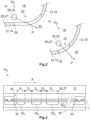
- FIG 2a a second embodiment of the cladding component 10 2 according to the invention is shown in a sectional view.
- the through opening 22 extends not only over the essentially horizontal section 14, but also at least partially over the transition between the essentially horizontal and the essentially vertical section 16. Since the through opening 22 is somewhat wider than in the first embodiment due to the extension to the transition, the light can radiate laterally from the panel component 10 2 , whereby a larger area in the vicinity of the vehicle that is further away from the vehicle can be illuminated. Accordingly, the light guide 27 is arranged in a different rotational position compared to the first embodiment 10 1 . The main exit direction of the light from the light guide 27 is marked with the arrow P.
- FIG. 2b a third embodiment of the cladding component 10 3 according to the invention is shown in a sectional view.
- the through-opening 22 extends only in the transition between the essentially horizontal and the essentially vertical section 14, 16.
- the rotational position of the light guide 27 is adjusted accordingly in order to enable optimal emission of the light.
- the main exit direction of the light from the light guide 27 is marked with the arrow P.
- the cladding components it is not absolutely necessary for the cladding components to have a substantially horizontal and/or substantially vertical section 14, 16. Rather, the embodiments described in the Figures 1 and 2 that the through-openings 22 can be arranged not only in a flat but also in a curved wall section. As already mentioned, In many countries, safety regulations stipulate that white light must not be emitted from the side of a vehicle. However, since white light provides the best illumination of the area around the vehicle, the lateral emission of white light must be avoided. The Figures 2a and 2b The embodiments 10 2 and 10 3 shown meet these safety requirements.
- a fourth embodiment of the cladding component 10 4 according to the invention is shown in a top view.
- the cladding component 10 4 comprises a first through-opening 22 1 , a second through-opening 22 2 and a third through-opening 22 3 .
- a first light source 34 1 and a second light source 34 2 are arranged at a first end 32 and a second end 36 of the rigid light guide 27.
- the two light sources 34 1 and 34 2 are connected to the two ends 32, 36 of the rigid light guide, but this does not necessarily have to be the case. It only has to be ensured that light can be coupled into the rigid light guide 27.
- the two light sources 34 1 , 34 2 are each designed as an LED board 40 with at least one LED.
- the light guide 27 of the lighting device 26 runs slightly above the inner edge 29 of the through openings 22, which due to the selected type of representation in Figure 3 is concealed.
- the LED boards 40 can have a receptacle or a housing with which the light guide 27 can be positioned in relation to the light source 34 such that the light generated can be optimally coupled into the light guide 27.
- the LED board 40 can be arranged on the cladding component 10 4 such that the light guide 27 runs at the desired distance from the through openings 22.
- the dashed line M is intended to represent the center of the light guide 27 in relation to a longitudinal axis L of the light guide 27. For reasons of clarity, only a first half of the light guide 27 is shown in full, with the second half being a mirror image of the first half, but this does not necessarily have to be the case.
- the light guide 27 has a number of notches 30 over its entire length, which are at a constant distance from one another.
- the notches 30 can thus be provided independently of the position and size of the through openings 22, which facilitates their manufacture.
- the first through opening 22 1 has the smallest distance A from the first light source 34 1
- the third through opening 22 3 has the greatest distance A from the first light source 34 1 .
- the first through opening 22 1 has a first extension E 1 , the second through opening 22 2 a second extension E 2 and the third through opening 22 3 a third extension E 3 , each of which runs along the longitudinal axis L of the light guide 27.
- the first extension E 1 is smaller than the second extension E 2 , which in turn is smaller than the third extension E 3 . Consequently, the extent E of the through openings 22 increases with increasing distance A of the through openings 22 to the first light source 34 1 .
- first through-opening 22 1 has a first distance D 1 to the second through-opening 22 2 and the second through-opening 22 2 has a second distance D 2 to the third through-opening 22.
- the first distance D 1 is greater than the second distance D 2 .
- Both the changes in the extension E and the distances D serve to compensate for the decrease in the illuminance, which increases with increasing distance A to the first Light source 34 1 is amplified, in order to achieve the most uniform possible illumination of the area surrounding the vehicle.
- FIG 4 an example of the cladding component 10 5 is shown using a top view.
- the structure of the cladding component 10 5 is largely similar to that of the fourth embodiment 10 4 .
- the dashed line M marks the center of the light guide 27 in relation to the longitudinal axis L.
- the cladding component 10 5 has four through openings 22 1 to 22 4 , each of which has the same extension E along the longitudinal axis of the light guide 27. Furthermore, the distance D between the four through openings 22 is always the same.
- the light guide 27 has the notches 30 only in the area of the through openings 22.
- the number of notches 30 per through opening 22 increases with increasing distance A of the through opening 22 from the light guide 27. Accordingly, the distance between two notches 30 is smaller the further the through opening 22 in question is from the first light source 34.
- the first and second light sources 34, 38, the through-openings and the light guide 27 are arranged on a separate wall section 42 1 according to a first embodiment, which is connected to the remaining wall 12 of the cladding component 10 4 and 10 5 in a manner not shown in detail.
- FIG. 5a the first embodiment and in Figure 5b a second embodiment of the separate wall section 42 1 , 42 2 and the light sources 34 1 and 34 2 arranged on it are shown without the light guide 27, so that the position of the through openings 22 1 to 22 4 is clearly visible. While in the first embodiment of the separate wall section 42 1 the through openings 22 1 to 22 4 are arranged in alignment along the longitudinal axis L, in the second embodiment 42 2 they are arranged laterally offset from one another. The offset arrangement of the through openings 22 1 to 22 4 according to the second embodiment of the separate wall section 42 2 makes it possible to illuminate a wider area around the vehicle.
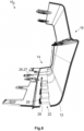
- FIG. 6 a sixth embodiment of the cladding component 10 6 according to the invention is shown in a perspective view. It can be seen that the through openings 22 are located within the essentially horizontally extending section 14 of the cladding component 10 6 and the light guide 27 is arranged along the inner edge 29 of the through openings 22.
- the dimensions of the cladding component 10 do not need to be changed in order to provide it with the light source 34 and the lighting device 26.
- the additional weight caused by the light source 34 and the lighting device 26 is approximately 300 g, which is within acceptable limits.
- the illuminated area is approximately 1200 to 1400 mm in the longitudinal direction of the vehicle and approximately 400 to 600 mm in the transverse direction of the vehicle.
- the extension E of the through openings 22 can have values from 10 to 300 mm and the distance D values between 5 and 25 mm (cf. Figures 3 and 4 ).
- the width of the through openings 22 can take on values between 5 and 25 mm.
- the illuminance is approximately between 4 and 50 lx (lux) on the floor.
- the power consumption of the LED boards 40 used is preferably 16 W (watts).
- the light guide 27 can, for example, have a length of 650 to 900 mm and a diameter of 4 to 5.5 mm.
Landscapes
- Engineering & Computer Science (AREA)
- Mechanical Engineering (AREA)
- Lighting Device Outwards From Vehicle And Optical Signal (AREA)
- Arrangements Of Lighting Devices For Vehicle Interiors, Mounting And Supporting Thereof, Circuits Therefore (AREA)
Claims (6)
- Pièce d'habillage de véhicule comprenant :- une paroi (12) délimitant un volume intérieur (18) de la pièce d'habillage (10),- plusieurs orifices traversants (22) qui traversent la paroi (12), et- une installation d'éclairage (26) dans le volume intérieur (18) de la pièce d'habillage (10), qui est relié à la source lumineuse (34) et comporte un guide de lumière (27) installé par rapport aux orifices traversants (22) pour que la lumière issue du guide de lumière (27) puisse traverser les orifices traversants (22),
pièce d'habillage caractérisée en ce que- le guide de lumière (27) présente des segments de découplage (28) dans la région des orifices traversants (22), segments à travers lesquels la lumière peut sortir du guide de lumière (26),* les orifices traversants (22) ayant une extension (E) parallèle à l'axe longitudinal (L) du guide de lumière (27), l'extension (E) allant en croissant avec la distance croissante (A) entre les orifices traversants (22) et la source de lumière (34), et/ou* chaque fois deux orifices traversants voisins (22) sont écartés l'un de l'autre d'une distance (D) qui est parallèle au guide de lumière (27), la distance (D) diminuant avec l'augmentation de la distance (A) des orifices traversants (22) par rapport à la source de lumière (34). - Pièce d'habillage selon la revendication 1,
caractérisée en ce que
la source lumineuse (34) est installée dans la pièce d'habillage (10). - Pièce d'habillage selon la revendication 2,
caractérisée en ce que
la source de lumière (34) comprend une ou deux platines de LED (40). - Pièce d'habillage selon l'une des revendications précédentes,
caractérisée en ce que
les orifices traversants (22) sont fermés avec une couche transparente (24). - Véhicule comprenant une pièce d'habillage (10) selon l'une des revendications 1 à 4,
caractérisé en ce que
la pièce d'habillage (10) est installée sur le véhicule de façon que la lumière passant dans les orifices traversants (22) soit rayonnée vers le sol pour l'utilisation appropriée du véhicule. - Véhicule selon la revendication 5,
caractérisé en ce que
la pièce d'habillage (10) est un habillage latéral, un marchepied ou un parechoc du véhicule.
Priority Applications (1)
| Application Number | Priority Date | Filing Date | Title |
|---|---|---|---|
| EP15181725.1A EP3132972B1 (fr) | 2015-08-20 | 2015-08-20 | Composant d'habillage pour véhicule |
Applications Claiming Priority (1)
| Application Number | Priority Date | Filing Date | Title |
|---|---|---|---|
| EP15181725.1A EP3132972B1 (fr) | 2015-08-20 | 2015-08-20 | Composant d'habillage pour véhicule |
Publications (2)
| Publication Number | Publication Date |
|---|---|
| EP3132972A1 EP3132972A1 (fr) | 2017-02-22 |
| EP3132972B1 true EP3132972B1 (fr) | 2025-01-01 |
Family
ID=53900774
Family Applications (1)
| Application Number | Title | Priority Date | Filing Date |
|---|---|---|---|
| EP15181725.1A Active EP3132972B1 (fr) | 2015-08-20 | 2015-08-20 | Composant d'habillage pour véhicule |
Country Status (1)
| Country | Link |
|---|---|
| EP (1) | EP3132972B1 (fr) |
Families Citing this family (1)
| Publication number | Priority date | Publication date | Assignee | Title |
|---|---|---|---|---|
| FR3075709A1 (fr) * | 2017-12-22 | 2019-06-28 | Psa Automobiles Sa | Vehicule automobile comportant un systeme de projection de motifs lumineux au sol |
Citations (7)
| Publication number | Priority date | Publication date | Assignee | Title |
|---|---|---|---|---|
| US20020054488A1 (en) * | 2000-08-11 | 2002-05-09 | Enplas Corporation | Light guide plate, surface light source device and display |
| US20030169384A1 (en) * | 2000-08-16 | 2003-09-11 | Enplas Corporation | Light guide plate, surface light source device and liquid crystal display |
| US20040130883A1 (en) * | 2002-12-17 | 2004-07-08 | Charles Leu | Surface light source and light guide plate having differently configured dots |
| DE202004008681U1 (de) * | 2004-06-02 | 2004-08-26 | Yang, Chang-An, Sijhih | Lichtführender Aufbau für Bodenwannenkanten in Automobilen |
| DE69735125T2 (de) * | 1996-10-25 | 2006-09-14 | Omron Corp. | Oberflächenlichtquelle und flüssigkristallanzeige, tragbares telefon, sowie ein die oberflächenlichtquelle verwendendes informationsendgerät |
| US20090003002A1 (en) * | 2006-01-27 | 2009-01-01 | Opto Design, Inc. | Planar Illumination Light Source Device and Planar Illumination Light Device Using The Planar Illumination Light Source Device |
| EP2028046A1 (fr) * | 2007-08-22 | 2009-02-25 | CCL Design GmbH | Corps de décoration |
Family Cites Families (6)
| Publication number | Priority date | Publication date | Assignee | Title |
|---|---|---|---|---|
| US6655824B2 (en) * | 1999-08-11 | 2003-12-02 | Brian N. Tufte | Lighting apparatus |
| DE10055561A1 (de) * | 2000-11-09 | 2002-05-23 | Hella Kg Hueck & Co | Beleuchtungseinrichtung |
| DE102008056985A1 (de) * | 2008-11-12 | 2010-05-20 | Hella Kgaa Hueck & Co. | Zierleuchteneinheit für Fahrzeuge |
| US8235568B2 (en) | 2010-02-26 | 2012-08-07 | Nissan North America, Inc. | Security lighting for a vehicle |
| US9812042B2 (en) * | 2012-10-29 | 2017-11-07 | Innotec Corp. | Lighted trim assembly and perforated member therefor |
| TWM493492U (zh) * | 2014-05-28 | 2015-01-11 | Desity Traffic Ind Co Ltd | 車輛用發光側踏板 |
-
2015
- 2015-08-20 EP EP15181725.1A patent/EP3132972B1/fr active Active
Patent Citations (7)
| Publication number | Priority date | Publication date | Assignee | Title |
|---|---|---|---|---|
| DE69735125T2 (de) * | 1996-10-25 | 2006-09-14 | Omron Corp. | Oberflächenlichtquelle und flüssigkristallanzeige, tragbares telefon, sowie ein die oberflächenlichtquelle verwendendes informationsendgerät |
| US20020054488A1 (en) * | 2000-08-11 | 2002-05-09 | Enplas Corporation | Light guide plate, surface light source device and display |
| US20030169384A1 (en) * | 2000-08-16 | 2003-09-11 | Enplas Corporation | Light guide plate, surface light source device and liquid crystal display |
| US20040130883A1 (en) * | 2002-12-17 | 2004-07-08 | Charles Leu | Surface light source and light guide plate having differently configured dots |
| DE202004008681U1 (de) * | 2004-06-02 | 2004-08-26 | Yang, Chang-An, Sijhih | Lichtführender Aufbau für Bodenwannenkanten in Automobilen |
| US20090003002A1 (en) * | 2006-01-27 | 2009-01-01 | Opto Design, Inc. | Planar Illumination Light Source Device and Planar Illumination Light Device Using The Planar Illumination Light Source Device |
| EP2028046A1 (fr) * | 2007-08-22 | 2009-02-25 | CCL Design GmbH | Corps de décoration |
Also Published As
| Publication number | Publication date |
|---|---|
| EP3132972A1 (fr) | 2017-02-22 |
Similar Documents
| Publication | Publication Date | Title |
|---|---|---|
| EP2151899B1 (fr) | Système de bande lumineuse | |
| EP2762361B1 (fr) | Unité d'éclairage | |
| DE102011103319B4 (de) | In ein Schiebedach oder ein Abdunklungssystem integrierte Umgebungsbeleuchtung | |
| DE10025810A1 (de) | Leuchteneinheit, insbesondere für Außenrückblickspiegel von Fahrzeugen, vorzugsweise von Kraftfahrzeugen | |
| EP3144182B1 (fr) | Composant d'habillage pour véhicule et véhicule associé | |
| DE202005014268U1 (de) | Fahrzeugleuchte mit einer einstückigen Lichtleiter-Blenden-Einheit | |
| EP2287042A1 (fr) | Dispositif d'éclairage pour un habitacle de véhicule | |
| WO2020043532A1 (fr) | Dispositif d'éclairage destiné à un véhicule automobile | |
| EP0779180B1 (fr) | Feu latéral utilisable comme indicateur de direction ou de côté | |
| DE102009055427B4 (de) | Kraftfahrzeuginnenverkleidungsteil mit Lichtquelle | |
| WO2005063526A1 (fr) | Plafonnier destine a l'habitacle d'un vehicule | |
| DE102006035842A1 (de) | Fahrzeugleuchte mit einer einstückigen Lichtleiter-Blenden-Einheit | |
| DE202005014267U1 (de) | Fahrzeugleuchte mit einem Lichtleiter mit zentraler Lichteinkopplung | |
| WO2005018989A1 (fr) | Dispositif d'eclairage pour vehicules a moteur | |
| DE19959609A1 (de) | Außenrückspiegel mit integriertem Fahrtrichtungsanzeiger | |
| WO2018234361A1 (fr) | Dispositif de commande de véhicule automobile et procédé de fabrication d'un dispositif de commande de véhicule automobile | |
| EP3132972B1 (fr) | Composant d'habillage pour véhicule | |
| DE19916845A1 (de) | Fahrzeugleuchte mit zwei Lichtquellen | |
| DE10159954A1 (de) | Innenraumeinbauteil, insbesondere für einen Fahrgastraum eines Kraftfahrzeugs | |
| EP2502783B1 (fr) | Dispositif de fixation pour un tapis supplémentaire | |
| EP1052145A2 (fr) | Dispositif de fixation d'un élément d'éclairage | |
| DE19916836B4 (de) | Signalleuchte an einer Fahrzeugscheibe | |
| DE20318691U1 (de) | Leuchte | |
| DE102012103309B4 (de) | Lichtleitvorrichtung | |
| DE102020204906A1 (de) | Heckklappe eines Fahrzeugs mit einer Beleuchtungsanordnung an einteiligem Außenblech |
Legal Events
| Date | Code | Title | Description |
|---|---|---|---|
| PUAI | Public reference made under article 153(3) epc to a published international application that has entered the european phase |
Free format text: ORIGINAL CODE: 0009012 |
|
| STAA | Information on the status of an ep patent application or granted ep patent |
Free format text: STATUS: THE APPLICATION HAS BEEN PUBLISHED |
|
| AK | Designated contracting states |
Kind code of ref document: A1 Designated state(s): AL AT BE BG CH CY CZ DE DK EE ES FI FR GB GR HR HU IE IS IT LI LT LU LV MC MK MT NL NO PL PT RO RS SE SI SK SM TR |
|
| AX | Request for extension of the european patent |
Extension state: BA ME |
|
| STAA | Information on the status of an ep patent application or granted ep patent |
Free format text: STATUS: REQUEST FOR EXAMINATION WAS MADE |
|
| 17P | Request for examination filed |
Effective date: 20170608 |
|
| RBV | Designated contracting states (corrected) |
Designated state(s): AL AT BE BG CH CY CZ DE DK EE ES FI FR GB GR HR HU IE IS IT LI LT LU LV MC MK MT NL NO PL PT RO RS SE SI SK SM TR |
|
| TPAC | Observations filed by third parties |
Free format text: ORIGINAL CODE: EPIDOSNTIPA |
|
| STAA | Information on the status of an ep patent application or granted ep patent |
Free format text: STATUS: EXAMINATION IS IN PROGRESS |
|
| 17Q | First examination report despatched |
Effective date: 20210430 |
|
| TPAC | Observations filed by third parties |
Free format text: ORIGINAL CODE: EPIDOSNTIPA |
|
| P01 | Opt-out of the competence of the unified patent court (upc) registered |
Effective date: 20230427 |
|
| GRAP | Despatch of communication of intention to grant a patent |
Free format text: ORIGINAL CODE: EPIDOSNIGR1 |
|
| STAA | Information on the status of an ep patent application or granted ep patent |
Free format text: STATUS: GRANT OF PATENT IS INTENDED |
|
| INTG | Intention to grant announced |
Effective date: 20240904 |
|
| GRAS | Grant fee paid |
Free format text: ORIGINAL CODE: EPIDOSNIGR3 |
|
| GRAA | (expected) grant |
Free format text: ORIGINAL CODE: 0009210 |
|
| STAA | Information on the status of an ep patent application or granted ep patent |
Free format text: STATUS: THE PATENT HAS BEEN GRANTED |
|
| AK | Designated contracting states |
Kind code of ref document: B1 Designated state(s): AL AT BE BG CH CY CZ DE DK EE ES FI FR GB GR HR HU IE IS IT LI LT LU LV MC MK MT NL NO PL PT RO RS SE SI SK SM TR |
|
| REG | Reference to a national code |
Ref country code: GB Ref legal event code: FG4D Free format text: NOT ENGLISH |
|
| REG | Reference to a national code |
Ref country code: DE Ref legal event code: R096 Ref document number: 502015017006 Country of ref document: DE |
|
| REG | Reference to a national code |
Ref country code: CH Ref legal event code: EP |
|
| REG | Reference to a national code |
Ref country code: IE Ref legal event code: FG4D Free format text: LANGUAGE OF EP DOCUMENT: GERMAN |
|
| REG | Reference to a national code |
Ref country code: LT Ref legal event code: MG9D |
|
| REG | Reference to a national code |
Ref country code: NL Ref legal event code: MP Effective date: 20250101 |
|
| PG25 | Lapsed in a contracting state [announced via postgrant information from national office to epo] |
Ref country code: NL Free format text: LAPSE BECAUSE OF FAILURE TO SUBMIT A TRANSLATION OF THE DESCRIPTION OR TO PAY THE FEE WITHIN THE PRESCRIBED TIME-LIMIT Effective date: 20250101 |
|
| PG25 | Lapsed in a contracting state [announced via postgrant information from national office to epo] |
Ref country code: FI Free format text: LAPSE BECAUSE OF FAILURE TO SUBMIT A TRANSLATION OF THE DESCRIPTION OR TO PAY THE FEE WITHIN THE PRESCRIBED TIME-LIMIT Effective date: 20250101 |
|
| PG25 | Lapsed in a contracting state [announced via postgrant information from national office to epo] |
Ref country code: PL Free format text: LAPSE BECAUSE OF FAILURE TO SUBMIT A TRANSLATION OF THE DESCRIPTION OR TO PAY THE FEE WITHIN THE PRESCRIBED TIME-LIMIT Effective date: 20250101 |
|
| PG25 | Lapsed in a contracting state [announced via postgrant information from national office to epo] |
Ref country code: ES Free format text: LAPSE BECAUSE OF FAILURE TO SUBMIT A TRANSLATION OF THE DESCRIPTION OR TO PAY THE FEE WITHIN THE PRESCRIBED TIME-LIMIT Effective date: 20250101 |
|
| PG25 | Lapsed in a contracting state [announced via postgrant information from national office to epo] |
Ref country code: IS Free format text: LAPSE BECAUSE OF FAILURE TO SUBMIT A TRANSLATION OF THE DESCRIPTION OR TO PAY THE FEE WITHIN THE PRESCRIBED TIME-LIMIT Effective date: 20250501 Ref country code: NO Free format text: LAPSE BECAUSE OF FAILURE TO SUBMIT A TRANSLATION OF THE DESCRIPTION OR TO PAY THE FEE WITHIN THE PRESCRIBED TIME-LIMIT Effective date: 20250401 |
|
| PG25 | Lapsed in a contracting state [announced via postgrant information from national office to epo] |
Ref country code: HR Free format text: LAPSE BECAUSE OF FAILURE TO SUBMIT A TRANSLATION OF THE DESCRIPTION OR TO PAY THE FEE WITHIN THE PRESCRIBED TIME-LIMIT Effective date: 20250101 |
|
| PG25 | Lapsed in a contracting state [announced via postgrant information from national office to epo] |
Ref country code: LV Free format text: LAPSE BECAUSE OF FAILURE TO SUBMIT A TRANSLATION OF THE DESCRIPTION OR TO PAY THE FEE WITHIN THE PRESCRIBED TIME-LIMIT Effective date: 20250101 Ref country code: PT Free format text: LAPSE BECAUSE OF FAILURE TO SUBMIT A TRANSLATION OF THE DESCRIPTION OR TO PAY THE FEE WITHIN THE PRESCRIBED TIME-LIMIT Effective date: 20250502 |
|
| PG25 | Lapsed in a contracting state [announced via postgrant information from national office to epo] |
Ref country code: GR Free format text: LAPSE BECAUSE OF FAILURE TO SUBMIT A TRANSLATION OF THE DESCRIPTION OR TO PAY THE FEE WITHIN THE PRESCRIBED TIME-LIMIT Effective date: 20250402 Ref country code: BG Free format text: LAPSE BECAUSE OF FAILURE TO SUBMIT A TRANSLATION OF THE DESCRIPTION OR TO PAY THE FEE WITHIN THE PRESCRIBED TIME-LIMIT Effective date: 20250101 |
|
| PG25 | Lapsed in a contracting state [announced via postgrant information from national office to epo] |
Ref country code: CZ Free format text: LAPSE BECAUSE OF FAILURE TO SUBMIT A TRANSLATION OF THE DESCRIPTION OR TO PAY THE FEE WITHIN THE PRESCRIBED TIME-LIMIT Effective date: 20250101 |
|
| PG25 | Lapsed in a contracting state [announced via postgrant information from national office to epo] |
Ref country code: SE Free format text: LAPSE BECAUSE OF FAILURE TO SUBMIT A TRANSLATION OF THE DESCRIPTION OR TO PAY THE FEE WITHIN THE PRESCRIBED TIME-LIMIT Effective date: 20250101 |
|
| REG | Reference to a national code |
Ref country code: DE Ref legal event code: R097 Ref document number: 502015017006 Country of ref document: DE |
|
| PG25 | Lapsed in a contracting state [announced via postgrant information from national office to epo] |
Ref country code: SM Free format text: LAPSE BECAUSE OF FAILURE TO SUBMIT A TRANSLATION OF THE DESCRIPTION OR TO PAY THE FEE WITHIN THE PRESCRIBED TIME-LIMIT Effective date: 20250101 |
|
| PG25 | Lapsed in a contracting state [announced via postgrant information from national office to epo] |
Ref country code: DK Free format text: LAPSE BECAUSE OF FAILURE TO SUBMIT A TRANSLATION OF THE DESCRIPTION OR TO PAY THE FEE WITHIN THE PRESCRIBED TIME-LIMIT Effective date: 20250101 |
|
| PGFP | Annual fee paid to national office [announced via postgrant information from national office to epo] |
Ref country code: DE Payment date: 20250819 Year of fee payment: 11 |
|
| PG25 | Lapsed in a contracting state [announced via postgrant information from national office to epo] |
Ref country code: IT Free format text: LAPSE BECAUSE OF FAILURE TO SUBMIT A TRANSLATION OF THE DESCRIPTION OR TO PAY THE FEE WITHIN THE PRESCRIBED TIME-LIMIT Effective date: 20250101 |
|
| PGFP | Annual fee paid to national office [announced via postgrant information from national office to epo] |
Ref country code: GB Payment date: 20250822 Year of fee payment: 11 |
|
| PGFP | Annual fee paid to national office [announced via postgrant information from national office to epo] |
Ref country code: FR Payment date: 20250827 Year of fee payment: 11 |
|
| PG25 | Lapsed in a contracting state [announced via postgrant information from national office to epo] |
Ref country code: EE Free format text: LAPSE BECAUSE OF FAILURE TO SUBMIT A TRANSLATION OF THE DESCRIPTION OR TO PAY THE FEE WITHIN THE PRESCRIBED TIME-LIMIT Effective date: 20250101 |
|
| PG25 | Lapsed in a contracting state [announced via postgrant information from national office to epo] |
Ref country code: RO Free format text: LAPSE BECAUSE OF FAILURE TO SUBMIT A TRANSLATION OF THE DESCRIPTION OR TO PAY THE FEE WITHIN THE PRESCRIBED TIME-LIMIT Effective date: 20250101 |
|
| PG25 | Lapsed in a contracting state [announced via postgrant information from national office to epo] |
Ref country code: SK Free format text: LAPSE BECAUSE OF FAILURE TO SUBMIT A TRANSLATION OF THE DESCRIPTION OR TO PAY THE FEE WITHIN THE PRESCRIBED TIME-LIMIT Effective date: 20250101 |
|
| PLBE | No opposition filed within time limit |
Free format text: ORIGINAL CODE: 0009261 |
|
| STAA | Information on the status of an ep patent application or granted ep patent |
Free format text: STATUS: NO OPPOSITION FILED WITHIN TIME LIMIT |
|
| REG | Reference to a national code |
Ref country code: CH Ref legal event code: L10 Free format text: ST27 STATUS EVENT CODE: U-0-0-L10-L00 (AS PROVIDED BY THE NATIONAL OFFICE) Effective date: 20251112 |
|
| 26N | No opposition filed |
Effective date: 20251002 |
|
| REG | Reference to a national code |
Ref country code: CH Ref legal event code: H13 Free format text: ST27 STATUS EVENT CODE: U-0-0-H10-H13 (AS PROVIDED BY THE NATIONAL OFFICE) Effective date: 20260324 |
|
| PG25 | Lapsed in a contracting state [announced via postgrant information from national office to epo] |
Ref country code: MC Free format text: LAPSE BECAUSE OF FAILURE TO SUBMIT A TRANSLATION OF THE DESCRIPTION OR TO PAY THE FEE WITHIN THE PRESCRIBED TIME-LIMIT Effective date: 20250101 |
|
| PG25 | Lapsed in a contracting state [announced via postgrant information from national office to epo] |
Ref country code: LU Free format text: LAPSE BECAUSE OF NON-PAYMENT OF DUE FEES Effective date: 20250820 |
|
| PG25 | Lapsed in a contracting state [announced via postgrant information from national office to epo] |
Ref country code: CH Free format text: LAPSE BECAUSE OF NON-PAYMENT OF DUE FEES Effective date: 20250831 |