EP3133018B1 - Dispositif d'affichage et systeme de porte et avion equipe d'un tel dispositif d'affichage - Google Patents
Dispositif d'affichage et systeme de porte et avion equipe d'un tel dispositif d'affichage Download PDFInfo
- Publication number
- EP3133018B1 EP3133018B1 EP15181638.6A EP15181638A EP3133018B1 EP 3133018 B1 EP3133018 B1 EP 3133018B1 EP 15181638 A EP15181638 A EP 15181638A EP 3133018 B1 EP3133018 B1 EP 3133018B1
- Authority
- EP
- European Patent Office
- Prior art keywords
- signal
- sensor
- door
- aircraft
- activation
- Prior art date
- Legal status (The legal status is an assumption and is not a legal conclusion. Google has not performed a legal analysis and makes no representation as to the accuracy of the status listed.)
- Active
Links
Images


Classifications
-
- B—PERFORMING OPERATIONS; TRANSPORTING
- B64—AIRCRAFT; AVIATION; COSMONAUTICS
- B64C—AEROPLANES; HELICOPTERS
- B64C1/00—Fuselages; Constructional features common to fuselages, wings, stabilising surfaces or the like
- B64C1/14—Windows; Doors; Hatch covers or access panels; Surrounding frame structures; Canopies; Windscreens accessories therefor, e.g. pressure sensors, water deflectors, hinges, seals, handles, latches, windscreen wipers
- B64C1/1407—Doors; surrounding frames
-
- B—PERFORMING OPERATIONS; TRANSPORTING
- B64—AIRCRAFT; AVIATION; COSMONAUTICS
- B64D—EQUIPMENT FOR FITTING IN OR TO AIRCRAFT; FLIGHT SUITS; PARACHUTES; ARRANGEMENT OR MOUNTING OF POWER PLANTS OR PROPULSION TRANSMISSIONS IN AIRCRAFT
- B64D45/00—Aircraft indicators or protectors not otherwise provided for
- B64D45/0015—Devices specially adapted for the protection against criminal attack, e.g. anti-hijacking systems
- B64D45/0018—Devices specially adapted for the protection against criminal attack, e.g. anti-hijacking systems means on aircraft for restricting unauthorized access to the aircraft
-
- G—PHYSICS
- G08—SIGNALLING
- G08B—SIGNALLING SYSTEMS, e.g. PERSONAL CALLING SYSTEMS; ORDER TELEGRAPHS; ALARM SYSTEMS
- G08B13/00—Burglar, theft or intruder alarms
- G08B13/02—Mechanical actuation
- G08B13/08—Mechanical actuation by opening, e.g. of door, of window, of drawer, of shutter, of curtain, of blind
-
- G—PHYSICS
- G08—SIGNALLING
- G08B—SIGNALLING SYSTEMS, e.g. PERSONAL CALLING SYSTEMS; ORDER TELEGRAPHS; ALARM SYSTEMS
- G08B3/00—Audible signalling systems, e.g. audible personal calling systems
- G08B3/10—Audible signalling systems, e.g. audible personal calling systems using electric transmission; using electromagnetic transmission
-
- H—ELECTRICITY
- H04—ELECTRIC COMMUNICATION TECHNIQUE
- H04W—WIRELESS COMMUNICATION NETWORKS
- H04W4/00—Services specially adapted for wireless communication networks; Facilities therefor
- H04W4/02—Services making use of location information
- H04W4/023—Services making use of location information using mutual or relative location information between multiple location based services [LBS] targets or of distance thresholds
-
- H—ELECTRICITY
- H04—ELECTRIC COMMUNICATION TECHNIQUE
- H04W—WIRELESS COMMUNICATION NETWORKS
- H04W4/00—Services specially adapted for wireless communication networks; Facilities therefor
- H04W4/70—Services for machine-to-machine communication [M2M] or machine type communication [MTC]
-
- H—ELECTRICITY
- H04—ELECTRIC COMMUNICATION TECHNIQUE
- H04W—WIRELESS COMMUNICATION NETWORKS
- H04W4/00—Services specially adapted for wireless communication networks; Facilities therefor
- H04W4/80—Services using short range communication, e.g. near-field communication [NFC], radio-frequency identification [RFID] or low energy communication
Definitions
- the present invention relates to a display device for indicating unauthorized opening of a door of a ground-parked aircraft and a door assembly and an airplane having such a display device.
- security seals are complex in use, since they must be manually glued by a person, examined and removed without residue. In addition, their use is associated with false alarms because they are sensitive to moisture and dirt and may fall off and may be damaged even without unauthorized opening of a door due to relative thermal expansion between the door and fuselage. Furthermore, security seals may be forged or owned by unauthorized persons, and they must be continuously re-purchased as they are for single use only.
- US 2007/0176793 A1 describes an alarm system for an aircraft.
- the alarm system has distance sensors. When a Door or a cover of an access to the interior is moved, this is detected by the distance sensors. Then, a signal is sent from the distance sensors to the control device that triggers a warning tone.
- the alarm system is activated or deactivated via a remote control. This has an "on” button and an “off” button. If an open door has been detected, the audible alarm sounds continuously until the "off" button on the remote control is pressed.
- US 6,946,959 describes several alarm systems units that can be operated in a network.
- the alarm systems units are interconnected by means of radio frequency transmission.
- an alert signal is emitted.
- an action signal is transmitted to the other alarm units in the network.
- the alarm signal is automatically output.
- the composite of multiple alarm units is controlled by an alarm activator 20 which provides both the delivery of the alert signal and the action signal.
- a display device for indicating unauthorized opening of a door of an aircraft parked on the ground, in particular unattended.
- the display device has a sensor for detecting a distance between the sensor and an object located in a detection range of, for example, two to five meters in front of the sensor.
- an object is, in particular, a fixed component of the aircraft, which has a static reference position with respect to the sensor.
- other such objects may also be, in particular, persons approaching the door.
- the display device has a signaling device, which has a first state and a second state, and a reset device, which is coupled to the signaling device, and which, when a user performs a predetermined reset operation or reset operation, places the signaling device in the first one Condition.
- the reset device may be part of the signaling device or be formed as a separate component.
- the display device comprises an activation device which is adapted to provide as an output signal optionally a predetermined deactivation signal and a predetermined first activation signal.
- the activation device can be configured such that the provision of the deactivation signal or of the first activation signal is specifically triggered by a user undertaking a predetermined deactivation operation or a predetermined first activation operation on the activation device or a separate component of the display device or a separate device.
- the display device has a control device which is coupled to the sensor, the signaling device and the activation device. As a result, it can receive signals from the sensor and the activation device and deliver control signals to the signaling device.
- the control device is adapted to switch on receipt of the deactivation signal from the activation device in a first mode and to change on receipt of the first activation signal from the activation device in a second mode.
- the change to the first operating mode or to the second operating mode can preferably be confirmed by an optical or acoustic signaling or by different optical or acoustic signaling by means of an optional suitable optical or acoustic signaling device, which will be discussed in more detail later.
- the control means is adapted in the second mode of operation, which, in contrast to the first mode in which the opening of a door is not monitored, is a monitoring mode in which monitors the opening of a door in the manner described below is based on a sensor signal supplied by the sensor for the distance between the sensor and the object or an object is characteristic, detects a change in the distance between the sensor and the object and offset upon detection of a change in the distance, the signaling device until the execution of the predetermined reset operation in the second state, in particular by generating a corresponding control signal, which is supplied to the signaling device and to which the signaling device responds accordingly.
- the first state can not be established by establishing the original distance or a certain distance, such as closing the door.
- the control device effects the movement to the second state upon detection of each change.
- the control device is adapted to do so only at a predetermined minimum change, ie a change in the distance exceeding a predetermined amount, and / or a change in the distance over a predetermined minimum period. These measures can further reduce the risk of false alarms, as minor changes in spacing or short failures that are not caused by opening a door will not cause a change in the state of the signaling device.
- the control device is adapted so that it responds only to a change that corresponds to an increase in the distance or a reduction in the distance.
- the senor is attached to one of a stationary component, such as a bottom section, for example. a wall portion, a portion of a galley or a portion of a monument, interior of an aircraft spaced door of the aircraft or fixed to the stationary component arranged in such a way that the stationary component or the door is in the detection range of the sensor and a Opening the door causes a change in the distance of the sensor from the stationary component or the door.
- a stationary component such as a bottom section, for example. a wall portion, a portion of a galley or a portion of a monument, interior of an aircraft spaced door of the aircraft or fixed to the stationary component arranged in such a way that the stationary component or the door is in the detection range of the sensor and a Opening the door causes a change in the distance of the sensor from the stationary component or the door.
- the first activation signal is provided by the activation device to ensure that the signaling device is initially in the first state.
- a change of the signaling device from the first state to the second state which can be detected at any time by examination of the signaling device, indicates that the door has been opened.
- the display device may have a display, is displayed on the constantly or after user request, whether the signaling device is in its second state, or an optical display in the form of, for example, a light emitting diode.
- a change of the signaling device from the first state to the second state takes place without the door having been opened, namely when a person is inside the aircraft moved through the detection range of the sensor and this therefore detects a change in distance to an object.
- the signaling device since the signaling device is intended to monitor a parked aircraft on which there are typically no persons on board, this is even helpful, since events can also be detected in which a person accesses by a route other than through the monitored door Plane has procured.
- the display device has the advantage that once in an aircraft to monitor a door are arranged and then can be used over and over again, so that their use is very simple and cost effective in the long term. In addition, it is less sensitive to false alarms and manipulation as a security seal.
- the display device may have its own independent power supply for its operation, such as in particular a rechargeable or non-rechargeable battery, or else have a power supply connection for connection to an external power supply, in particular an on-board power supply network of an aircraft.
- the reset means and / or the activation means are provided as part of the control means, i. are formed by the control device or are implemented in it, or that the reset device and / or the activation device are provided as separate components. It is also possible that one of the two devices is provided as part of the control device and the other as a separate component.
- the control device may be provided, for example, in the form of an electronic unit or as part of an electronic unit. If the reset device or the activation device is provided as a separate component, then the respective device may preferably be part of the same electronic unit as the control device or else be provided on a separate electronic unit.
- the signaling device to a non-volatile electronic storage device.
- the first state and the second state correspond to different predetermined values stored in a predetermined memory area of the memory device.
- a predetermined storage area in which different values are stored can be. If one or more first predetermined values are stored in the memory area, the signaling device is in its first state, and if one or more second predetermined values are stored in the memory area, the signaling device is in its second state.
- Such a configuration of the signaling device is particularly easy to implement and particularly tamper-proof.
- the signaling device may further comprise an optical signal device for outputting an optical signal and / or an acoustic signal device for outputting an acoustic signal.
- the control device is then adapted to operate the optical signal device and / or the acoustic signal device for outputting the optical signal or the acoustic signal during or after the signaling device is put into the second state.
- the second state may include the output of the optical signal and / or the acoustic signal. Since the memory state of the memory device is not or can not be easily recognized from the outside, the provision of an optical signal device and / or an acoustic signal device has the advantage that an opening of a door is directly visible.
- the second state can still be determined by examining the memory state of the memory device.
- the senor is adapted to detect the distance based on the transit time of a signal received from the sensor or a separate signal output device emitted, reflected from the object and received by the sensor.
- the sensor may in particular be an ultrasonic sensor. This can periodically emit an acoustic signal in the ultrasonic range, which is reflected by objects located in the detection or monitoring area and reflected back to the sensor. From the time difference between emitted and incoming signal, the distance of the object from the sensor can be determined.
- ultrasonic sensors have a comparatively low weight and nevertheless permit precise measurement and an adjustable sensor behavior.
- the activation device has a receiver for receiving wireless signals and is adapted to provide the deactivation signal upon receipt of a first predefined wireless signal and the first activation signal upon receipt of a second predefined wireless signal.
- These wireless signals can be delivered, for example, by a dedicated remote control without which activation and deactivation is not possible.
- short range wireless signals may be used, such as NFC signals.
- the receiver is an RFID receiver
- the first and second predefined wireless signal can be generated by a RFID transmitter with a predefined identifier, which is preferably part of a system that also contains the display device.
- the RFID receiver and the RFID transmitter can be paired, so that the wireless signal received by the RFID receiver is examined for a predetermined identifier assigned to the RFID transmitter and / or the RFID receiver is expected, the wireless signal emitted by the RFID transmitter is encrypted with a predetermined encryption associated with the RFID transmitter so that the RFID receiver can verify the authenticity of the wireless signal or its origin from the RFID receiver.
- a dedicated key pair may be stored in the RFID receiver and the RFID transmitter.
- the RFID receiver may be an RFID reader that provides power to the operation of the RFID transmitter through an emitted interrogation signal when it is within a predetermined distance from the RFID reader and that may be an RFID tag. It then suffices in an advantageous manner to arrange the RFID transmitter, which is preferably designed as a portable unit, temporarily in the vicinity of the display device in order to actuate the activation device, ie this portable unit only has to be activated or deactivated for authorized activation Personnel are held to the display device.
- the RFID transmitter may include a switch to determine whether the first or the second wireless signal is transmitted, or the first and second wireless signals may be identical, and the activation means alternates between the provision of the signal each time this signal is received Deactivation signal and the first activation signal.
- the RFID reading device could transmit with its interrogation signal information about whether the control device is in the first operating mode or in the second operating mode, and that the RFID transmitter is adapted to determine the current one from the interrogation signal Determine operating mode and depending on the determined operating mode to send the first or the second wireless signal to the activation device, so that a change of operating mode takes place.
- the RFID transmitter is adapted to determine the current one from the interrogation signal Determine operating mode and depending on the determined operating mode to send the first or the second wireless signal to the activation device, so that a change of operating mode takes place.
- the activation device has a signal input for wireless or wired reception of external signals and is adapted to provide as an output signal the respective received external signal or to provide the deactivation signal when a first predetermined external signal is received and to provide the first activation signal when a second predetermined external signal is received.
- the deactivation signal or the first activation signal is provided when it is received as an external signal, i. generated externally and simply forwarded.
- the latter case allows the connection to a central or associated separate control - for example via an AFDX, CAN or the like or another data line which is present in an aircraft door - and thus possibly the possibility of simultaneous activation or deactivation of several display devices.
- the external signals can also be generated by a code input device, for example, or the code input device can be part of the activation device.
- the predetermined reset operation is receipt of a predefined wireless or wired reset signal by the display device.
- the remainder device may have a receiver for receiving wireless signals and in particular an RFID receiver, wherein the receiver or RFID receiver may be the same as described above the activation device has been described, or a receiver with the same characteristics, or the reset device may have a signal input for wireless or wired reception of external signals for which the same applies, as has been described for the signal input of the activation device.
- the display device is designed as a coherent, compact structural unit which can be arranged or fastened to a door or a door leaf of an aircraft door or which can be integrated into a door trim of an aircraft door.
- a coherent, compact structural unit which can be arranged or fastened to a door or a door leaf of an aircraft door or which can be integrated into a door trim of an aircraft door.
- the sensor, the signaling device, the reset device, the activation device and the control device - and possibly other components - such a cohesive, compact unit.
- Such a display device is particularly reliable and easy to retrofit, and no major modifications are required within the aircraft concerned, and in particular at a door.
- the display device further comprises an optical signal device for outputting an optical signal - such as the above-mentioned optical signal device, which is activated during or after putting the signaling device in the second state - and an acoustic signal device for outputting an acoustic signal - such as the above-mentioned Acoustic signaling device which is activated during or after putting the signaling device in the second state-which are also part of the assembly.
- optical signal device for outputting an optical signal - such as the above-mentioned optical signal device, which is activated during or after putting the signaling device in the second state -
- an acoustic signal device for outputting an acoustic signal - such as the above-mentioned Acoustic signaling device which is activated during or after putting the signaling device in the second state-which are also part of the assembly.
- they form together with the sensor, the signaling device, the reset device, the activation device and the control device - and possibly other components - the coherent, compact unit
- the controller is adapted to operate the optical signal device when approaching a person below a first threshold distance and the acoustic signal device when approaching a person below a second threshold distance, wherein the first limit distance is greater than the second threshold distance. If a person approaches the display device, this can initially output an optical signal, so that the person is already informed at a fairly large distance, that is, clearly more than an arm length, preferably at most 1.1 m, about this approach, eg. as explained further below - to indicate that an emergency slide is active.
- an additional acoustic signal can be emitted, which explicitly indicates to the person, for example, that the emergency slide is activated when a handle provided on the door is actuated is triggered.
- control device Since the control device is adapted to operate the optical signal device and the acoustic signal device at the approach of a person below the predetermined margins, this may be provided as a third mode in addition to the first mode and the second mode.
- the first mode is then, for example, a mode in which the display device is not active in total.
- the third operating mode can optionally be carried out at the same time as the second operating mode, ie that in a combined operating mode the control device is adapted both to change the distance between the sensor and an object, the signaling device to make to offset the predetermined reset operation in the second state as well as when approaching a person under at least one predetermined threshold distance at least one the optical signaling device and the acoustic signaling device to operate.
- the controller is then preferably further configured to switch between all available modes, ie, between the first, second, and third modes, and possibly the combined mode.
- the change can take place in the same way as described above for the change between the first and second modes.
- further corresponding activation signals may be provided to which the control device reacts accordingly.
- the control device in the second operating mode may be adapted in order to operate the optical signal device and the acoustic signal device when a person approaches the predetermined limit distance.
- the above-mentioned compact units may preferably have a housing with a mounting area and a viewing side. The attachment area is adapted to engage mechanically with the door panel or a fastener on the aircraft door.
- the housing is at least partially transparent in a portion housing the optical signal device.
- the housing shape therefore does not have to differ from that of a conventional warning lamp and the components integrated therein are largely protected from external influences, while the visibility of the optical signal device remains ensured.
- the display device is in advantageously suitable and adapted in particular for displaying an activation status of an emergency slide in an aircraft.
- aircraft doors can be coupled with an emergency slide release device, so that when the respective aircraft door is opened, an emergency slide arranged thereon is triggered.
- an escape slide release lever Before departure, an escape slide release lever is placed in an "armed” mode with the doors closed. After normal landing, the escape slide release lever is placed in a “disarmed” mode so that coupling with the emergency slide release device is released and the aircraft doors are normally open.
- a warning light may be installed in or on the aircraft door which provides a visual indication of the state of the emergency slide activation.
- a warning light may be installed in or on the aircraft door which provides a visual indication of the state of the emergency slide activation.
- the escape slide activation lever is left in the armed state and an emergency slide is inadvertently released when an aircraft door is opened resulting in damage near the aircraft and leads to high follow-up costs and indefinite downtime of the aircraft due to the necessary re-integration of the emergency slide. This is independent of the door structure and the aircraft manufacturer.
- the optical signal device is then used to generate a visually perceptible signal that indicates to a person that when opening a door of the aircraft, an emergency slide is triggered.
- any display devices can be used which in particular selectively generate a light signal, for example by a lighting device based on an incandescent lamp, an LED or a plurality thereof.
- the lighting device may be configured to emit a continuous light or a flashing light, wherein the optical perceptibility of a flashing light can exceed that of a continuous light.
- the acoustic signal device can, like each of the above-mentioned acoustic signal devices, have a tone generation unit with which an acoustically perceptible signal can be generated.
- the sound generating means may for this purpose comprise an electromagnetically or piezoelectrically operable loudspeaker or buzzer and, if required or desired, means for selectively outputting a signal sequence for reproducing a recorded or synthetic sound.
- the sensor in these embodiments is further capable of detecting an approach of a person to the sensor and thus to the display device housing it so that knowledge can be obtained as to whether and / or at what distance a person is in front of the sensor.
- the control device coupled thereto is capable of selectively operating the optical signal device and the acoustic signal device. Specifically, this means that the control device based on the distance of a person from the sensor or the display device can make a visual and / or audible warning, by which the person is advised that to expect when opening the door with a release of the emergency slide is.
- the display device is preferably configured and configured so that as in conventional warning lights by the optical signal device a continuous light or by the acoustic signal device a Treasurewarnton is generated as soon as the door opening lever is moved a sharp distance in the direction of door-opening when the emergency slide.
- the control device is connected to an external detector for detecting the position of the door opening lever.
- the display device As a result of the design of the display device as a compact structural unit which can be integrated into a door panel of the aircraft or arranged or fastened to an aircraft door, a conventional warning lamp for escape slide activation can be readily replaced by the display device according to the invention.
- the display device is preferably to be designed such that it is designed at least in a necessary area for attachment as a conventional warning light, so that the door panel and a corresponding cutout or a fastener arranged thereon need not be modified.
- the display device according to the invention thus has a very high potential for a retrofit solution (retrofit), because it would only have to be replaced by a conventional warning light by the display device according to the invention.
- control device has at least one activation signal input and is configured to activate or to interrupt the operation of the optical signal device and the acoustic signal device based on a second activation signal receivable via the activation signal input.
- the control device can make the operation of the optical signal device and the acoustic signal device dependent on the landing state of the aircraft and / or the position of an emergency slide activation lever located on the relevant door. This has the advantage that an appropriate monitoring is carried out only when landed aircraft and in a certain position standing emergency slide activation lever, if there is a risk that the door is opened without deactivating the emergency slide activation lever.
- a second activation signal which depends on the landing state of the aircraft, may be generated by a separate device when the aircraft is on the ground and transmitted to the activation signal input.
- Another second activation signal which depends on the position of the emergency slide activation lever, may be generated by another sensor located in or on the emergency slide activation lever, monitoring the position of the emergency slide activation lever, and transmitting a corresponding signal to the at least one activation signal input.
- an existing already on the emergency slide activation lever sensor can be used, provided that its output signal is available for the display device, or by a dedicated separate, eg retrofitted, sensor. It is also possible to combine several different second activation signals, eg a second activation signal indicative of the landing condition, and a second activation signal indicative of the position of the emergency slide activation lever.
- a second activation signal which depends on the landing state of the aircraft, can be generated and transmitted by a central, already existing system of the aircraft. It is advisable in these cases to connect the display device according to the invention for this purpose via a corresponding bus or a network with this central device, for example via an AFDX, CAN or the like. But it is also possible to connect the display device to a source of discrete or logical signals. The prerequisite for this is in all cases that a corresponding data line or individual line is present in the door or is subsequently integrated into it. But this could also be a wireless connection means or a data transmission system realized on the basis of the power line entering the door.
- the display device further comprises an acceleration measuring unit coupled to the control device with a G sensor, ie an accelerometer or an acceleration sensor, and / or inertial measuring unit with at least one inertial sensor for continuous or periodic detection of at least one directional acceleration
- a G sensor can preferably measure the acceleration along three spatial axes and is preferably based on MEMS technology.
- An inertial sensor could detect both acceleration along one of three spatial axes and angular acceleration about one of three spatial axes.
- a flight profile can be detected, which consists of a climb phase, a cruise with one or more cruising altitudes, a sinking phase and a subsequent roll phase in which the aircraft is strongly decelerated and acceleration in the vertical direction is negligible. It would also be possible to detect only a characteristic landing following a sinking phase, a significant longitudinal deceleration of the boat Aircraft and / or the obligatory turn that occurs after each landing when changing from runway to taxiway.
- the different methods may require different arrangements with differently configured G sensors or a different number of inertial sensors, when determining a landing impact could be sufficient for example a G-sensor or a single inertial sensor that detects the acceleration along the vertical axis of the aircraft.
- a G-sensor or a single inertial sensor that detects the acceleration along the vertical axis of the aircraft.
- the determination as to whether the aircraft is on the ground is therefore based on the display device according to the invention itself. Consequently, a connection to a bus or a network which may not be present in the door or door lining does not have to be retrofitted so that the display device according to the invention can be used very flexibly for a wide variety of aircraft types and aircraft doors.
- the display device and / or the acceleration measuring unit and / or inertial measuring unit with a device for specifying a direction of flight, ie on a right or left side of the fuselage. It makes sense to design the display device according to the invention as always the same component that can be integrated into many different aircraft doors.
- the acceleration measuring unit and / or inertial measuring unit integrated in the display device can therefore be aligned with the direction of flight in two different ways.
- the installation side of the display device must therefore be known to the direction of flight, to those of the acceleration measuring unit and / or inertial measuring unit supplied signals to be able to reliably identify the landing state of the aircraft.
- appropriate firmware in the controller may also offer to pretend with the help of bridgeable pins, ie a pin programming on the controller when installing the display device.
- the display device preferably has a housing with a mounting area and a visible side.
- the attachment portion is adapted to engage mechanically with the door panel or fastener on the aircraft door.
- the sensor and optionally one or more of the above-mentioned optical signal devices extend at least partially towards the visible side.
- the arrangement of the optical signal devices or optical signal devices in a region close to the visible side allows undisturbed perception of the respective generated and emitted optical signal.
- the sensor is also preferably arranged in a region near the side of the face in order to allow undisturbed monitoring of a detection or monitoring area located in front of the display device and thus in front of the door or door trim in the interior of the aircraft.
- This detection area is defined as a space lying in front of the aircraft door or as a surface area of a door or door lining by selecting and fine-tuning of the sensor and extends into the interior of the aircraft, that is facing away from the door inner side or door trim Area.
- the sensor and the respective optical signal device can be arranged side by side or one above the other on the visible side.
- an aircraft door assembly having a door panel having a first side and an opposite second side adapted to be mounted in an opening in a fuselage of an aircraft such that it is interposed between a closed position in which it closes the opening and the first side facing an interior of the aircraft and the second side facing outwardly, and an open position is movable, in which the opening is accessible.
- the door assembly further comprises a display device according to one of the above-explained embodiments, wherein the sensor is arranged on the door leaf, e.g. by being fixed or integrated in or on a door trim.
- an aircraft comprising a hull in which an opening is formed and a door leaf having a first side and an opposite second side.
- the door leaf is adapted to be mounted in the opening in such a way that it is between a closed position in which it closes the opening and the first side faces an interior of the aircraft and the second side faces outward, and an open one Movable position in which the opening is accessible.
- the aircraft has a stationary component, such as a floor, a wall portion, a portion of a galley or a portion of a monument, in the interior of the aircraft. The stationary component is spaced from the door leaf.
- the aircraft also has a display device according to one of the embodiments explained above.
- the sensor is arranged on the door leaf, as explained above with respect to the door arrangement, or on the stationary component in such a way that the stationary component or the door leaf is in the detection range of the sensor and an opening the door leaf causes a change in the distance of the sensor from the stationary component or the door leaf.
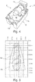
- FIG. 1 shows a display device 2 according to the invention, which has a housing 4 with a mounting portion 6 and a visible side 8.
- an in FIG. 1 concealed signaling device in the form of a non-volatile electronic memory 9 see FIG. 8
- an optical signal device 10 which by way of example has a plurality of lighting devices 18, an in FIG. 1 concealed activation device in the form of an RFID reader 11 (see FIG. 8 ), one in FIG. 1 concealed and connected to the memory 9 residual device in the form of another RFID reader 17 (see FIG. 8 ), one in FIG. 1 concealed acoustic signaling device 12 and a sensor 14 for detecting the distance of an object from the display device 2 are arranged.
- the optical signal device 10 and the sensor 14 are positioned below or next to one another, ie along a spatial axis, on the visible side 8, while the acoustic signal device 12 is positioned, for example, in the interior of the display device 2 away from the visible side 8.
- the attachment portion 6 may further comprise elastic retaining clips 15, which enter into a corresponding opening of a door panel with this a positive and / or non-positive connection upon insertion of the mounting portion.
- limit distance 32, 34 are reached, which may reach an object at most, so that the optical signal device 10 and the acoustic signal device 12 are operated.
- this can be done as described below with reference to FIGS Figures 2 and 6 can be achieved by defining an amount by which the distance to a defined object may at most change before the hint is stored in the memory 9.
- the activation device 11 For switching between the two operating modes, the activation device 11 is provided, which in the example is designed as an RFID reader. It is designed and configured to periodically transmit a wireless interrogation signal with a code assigned to it, and to respond to a particular wireless response signal received from a passive RFID tag powered by the interrogation signal.
- This RFID tag which forms a system together with the display device 2, is paired with the activation device 11, ie configured to respond to an interrogation signal with the code of the activation device 11 with the transmission of a response signal with a code assigned to the RFID tag responding.
- the activation device 11 examines the response signal to see if it contains the code of the RFID tag paired with it.
- the electronics unit 16 may include one or more other activation signal inputs 56, 58 to which an activation signal may be sent. This is used to initiate the operation of the optical signal device 10 and the acoustic signaling device 12 only then make as soon as the aircraft is on the ground and at any time the associated aircraft door can be opened, that is to activate the warning mode only in this case.
- the optical signal device 10 is separated in the embodiment shown only by a transparent cover 13 from the visible side 8 or arranged in a cutout therein, so that an unrestricted visibility of the optical signal device 10, i. the lighting means 18, which are suitable for generating a sufficiently bright light, pulsed or continuous.
- the optical signal device 10 has an example of a lettering 20 ("Slide Armed"), which is designed as the only non-translucent surface of the optical signal device 10.
- the lettering 20 can also be realized as the only light passage surface of the optical signal device 10.
- the sensor 14 is an example of an ultrasonic sensor which periodically emits ultrasonic signals and from the time difference between the emitted sound waves and received sound reflections, the distance to the relevant object located in front of the sensor.
- other types of sensors may be used, such as optical, camera-based, or radar-based sensors.
- the display device 2 is designed as a very compact unit that can be used instead of a conventional warning light in a door trim or the like. As indicated above, it is advisable, in order to avoid an excessive triggering of warning signals of optical or acoustic nature, to operate the optical signal device 10 and / or the acoustic signal device 12 only when the aircraft is on the ground and an opening of the aircraft door imminent. This can be realized particularly simply by receiving an activation signal at the activation signal input 56, 58, for which, however, a data line or a single line with a logical signal to a central unit on board the aircraft is necessary.
- the display device 2 is a here hidden concealment or inertial measurement device (inertial platform or IMU) 22 (or 48 in FIG. 8 ), which is adapted to detect the spatial movements of the aircraft and transmit them to the electronics unit 16.
- the landing of an aircraft can be determined by succinct events, such as a landing impact after a continuous descent. Once this event has occurred, the electronics unit 16 can perform the proximity detection and thereby controlled visual or audible warnings.
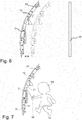
- FIG. 2 shows an example of an aircraft door 24 with a door panel 26, which faces the interior of the fuselage.
- the door 24 is opened from the inside of the aircraft.
- the display device 2 is integrated on or in the door panel 26, wherein the visible side 8 is turned into the interior of the aircraft.
- the senor 14 monitors a space 28 on the inside of the aircraft and defines a detection area 30.
- the electronics unit 16 may have a first limit distance 32 and define a second limit distance 34, wherein the electronic unit 16 operates the optical signal device 10 as soon as a person falls below the first limit distance 32 and wherein the acoustic signal device 12 is operated becomes as soon as a person falls below the second limit distance 34.
- the first limit distance 32 it is advisable to provide a distance of at most 1.1 m and preferably 0.9 m.
- the second limit distance 34 a distance of at most 0.5 m and preferably 0.35 m is recommended.
- the electronics unit 16 operates the optical signal device 10 and the acoustic signal device 12 to emit a continuous light or a permanent warning sound when the door opening lever is moved a predetermined distance in the direction of door opening while the emergency slide is activated.
- the electronics unit 16 is preferably connected via a further input to a sensor which monitors the position of the door opening lever.
- the detection area 30 of the sensor 14 is selected and oriented so that when the door 24 is closed, a stationary component 35 of the aircraft, such as a galley wall, is located in the detection area 30 at a defined distance from the sensor 14.
- a stationary component 35 of the aircraft such as a galley wall
- the electronics unit 16 When the electronics unit 16 is in its monitoring mode with the door 24 closed, it monitors whether the defined distance changes by more than a predefined threshold amount. Once this is the case, it is an indication of an opening of the door, which, like out FIG. 6 it can be seen, to an increase in the distance between the door 24 and the stationary Component 35 leads.
- a control signal to the memory 9 is output by the electronic unit, which causes a storage of a first predetermined value in a predetermined memory location of the memory 9.
- This value indicates that the door 24 has opened, and can only be reset by the reset means 17, which will be described below with reference to FIG. 8 is described.
- the storage of the first predetermined value can also be effected by an unauthorized person gaining access to the aircraft in a different way and moving through the detection area 30 of the sensor 14.
- FIG. 3 Figure 4 shows a four-sided view of the display device 2 showing a bottom 36 with an electrical connector 38 to be connected to a power supply of the door 24 and further coupled to a sensor, not shown, which monitors the emergency slide activating lever 31; and which also, depending on the type of aircraft, as outgoing cable whip with end-connected connector can be executed. Both can be realized via an activation signal, which depends on the position of the emergency slide activation lever 31, as well as on a dependent of the position of the emergency slide activation lever 31 power supply.
- a narrow end 40 of the viewing area 8 mainly has the sensor 14, which at in FIG. 2 directed installation is directed directly into the interior of the fuselage.
- the lighting devices 18 can be seen, which are distributed along the side wall 42 in the interior of the cover 13.
- the attachment region 6 is narrower than the viewing region 8, so that when the display device 2 is snapped in an opening, an edge 44 facing the attachment region 6 is located on an edge of the relevant one Can rest opening and the retaining clips 15 favor a flush contact of the edge 44 with the edge of the respective opening.
- the lettering 20 is arranged on an upper side 46 and occupies substantially the available width of the cover 13. Due to the transparency of the cover 13, further lighting devices 18 can be seen, which backlight the lettering 20.
- FIG. 4 shows the display device 2 further in a partially decomposed arrangement, in which case an integrated in the electronic unit 16 acceleration measuring unit 48 can be seen, which can detect the movement of the display device 2 and thus of the aircraft.
- an integrated in the electronic unit 16 acceleration measuring unit 48 can be seen, which can detect the movement of the display device 2 and thus of the aircraft.
- This event may trigger an activation signal that initiates the activation of proximity detection in the area in front of the door 24.
- a diagram in FIG. 5 also shows two preferred sound beams 50 and 52 of the ultrasonic sensor 14, wherein the sound beam 50 to a plate aligned ultrasonic sensor and the sound beam 52 to an ultrasonic sensor with a tube having a diameter of, for example, 27 mm.
- the sound beam should be set as narrow as possible, so that a width of well below one meter, and preferably of 0.3 to 0.7 m is achieved.
- the detection area 28 is thus quite narrow and can hide laterally further away persons and objects.
- the use of a Aligned plate allows a comparison with the solution with pipe slightly widened sound beam 50th
- FIG. 7 a person 54 is shown, which approaches the door 24 and in this case has already exceeded the first limit distance 32 and reaches the second limit distance. At the same time, an optical warning and an audible warning are emitted, so that the person 54 is clearly warned against opening the door 24 with the emergency slide activation lever 31 in an activation position.
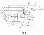
- FIG. 8 an embodiment of the display device 2 in a schematic, block-based representation.
- the ultrasonic sensor 14 and the acceleration measuring unit 48 are connected to the electronics unit 16, which also has three activation signal inputs 56, 58 and 59 on a logic module 76.
- the acceleration measurement unit 48 may generate via an appropriate logic circuit 60 an activation signal representing a successful landing, in which case the activation signal is sent to the activation signal input 56.
- Another activation signal applied to a terminal 74 connected to a positioner for an emergency slide activation lever position detector may be sent to the second activation signal input 58 which represents an activation position of the emergency slide activation lever. If the aircraft is on the ground and the escape slide activation lever is in an activation position, monitoring of the detection area 30 is initiated.
- an optical signaling 62 and / or an acoustic signaling 64 is triggered via an output signal stage 78.
- the activation or deactivation signal for switching between the modes may, as has already been explained above, are sent to the activation signal input 59.
- the reset device 17 is connected to the memory 9 and is, similar to the activation device 11, designed as an RFID reader. It is designed and configured to periodically transmit a wireless interrogation signal with a code assigned to it, and to respond to a particular wireless response signal received from a passive RFID tag powered by the interrogation signal.
- This RFID tag which together with the display device 2 forms a system, is paired with the reset device 17, i. configured to respond to an interrogation signal with the code of the reset device 17 with the transmission of a response signal with a code assigned to the RFID tag.
- the reset device 17 examines the response signal to see if it contains the code of the paired RFID tag. Only if this is the case does it send a reset signal to the memory 9 which causes the memory 9 to store a second predetermined value different from the first predetermined value in the predetermined memory location. In this way, the memory 9 is prepared for a next monitoring.
- filters 66 and 68 of the acceleration measuring unit 48 and the ultrasonic sensor 14 are connected downstream in order to achieve a desired signal quality.
- a power supply unit 70 is further connected to the terminal 38.
- a pin programming unit 72 is connected to or integrated with the display device, in particular to indicate the orientation of the display device 2 relative to the direction of flight.
Landscapes
- Engineering & Computer Science (AREA)
- Aviation & Aerospace Engineering (AREA)
- Mechanical Engineering (AREA)
- Power-Operated Mechanisms For Wings (AREA)
- Geophysics And Detection Of Objects (AREA)
Claims (12)
- Dispositif d'indication destiné à indiquer une ouverture non autorisée d'une porte (24) d'un aéronef stationné au sol, comprenant
un capteur (14) destiné à détecter une distance entre le capteur (14) et un objet qui se trouve dans une zone de détection (30) devant le capteur (14),
un dispositif de signalisation (9) qui possède un premier état et un deuxième état,
un dispositif de réarmement (17) connecté au dispositif de signalisation (9), qui est conçu pour amener le dispositif de signalisation (9) dans le premier état lorsqu'une opération de réarmement prédéterminée est effectuée par un utilisateur,
un dispositif d'activation (11) qui est conçu pour délivrer au choix, en tant que signal de sortie, un signal de désactivation prédéterminé et un premier signal d'activation prédéterminé, et
un dispositif de commande (16) qui est connecté au capteur (14), au dispositif de signalisation (9) et au dispositif d'activation (11) et qui est conçu pour- basculer dans un premier mode de fonctionnement lors de la réception du signal de désactivation et- lors de la réception du premier signal de désactivation, basculer dans un deuxième mode de fonctionnement dans lequel, en se basant sur un signal de capteur délivré par le capteur (14) qui est caractéristique de la distance entre le capteur (14) et l'objet, il détecte une modification de la distance entre le capteur (14) et l'objet et, lors de la détection d'une modification, amène le dispositif de signalisation (9) dans le deuxième état jusqu'à ce que l'opération de réarmement prédéterminée soit effectuée, de telle sorte qu'après avoir monté le capteur (14) au niveau d'une porte (24) d'un aéronef espacée d'un composant fixe (35) dans l'espace intérieur de l'aéronef ou niveau du composant fixe (35) de manière à ce que le composant fixe (35) ou la porte (24) se trouve dans la zone de détection (30) du capteur (14) et qu'une ouverture de la porte (24) produise une modification de la distance entre le capteur (14) et le composant fixe (35) ou la porte (24), et qu'ensuite la fourniture du premier signal d'activation par le dispositif d'activation (11) alors que la porte (24) est fermée, un basculement du dispositif de signalisation (9) du premier état dans le deuxième état indique que la porte (24) a été ouverte,le dispositif d'indication étant réalisé sous la forme d'un module compact cohérent qui peut être intégré dans un habillage de porte (26) d'une porte d'aéronef (24), le dispositif d'indication possédant un dispositif de signalement visuel (10) destiné à délivrer un signal visuel (62), lequel est activé au moment d'amener ou après avoir amené le dispositif de signalisation (9) dans le deuxième état,
le dispositif d'indication possédant un dispositif de signalement sonore (12) destiné à délivrer un signal sonore (64), lequel est activé au moment d'amener ou après avoir amené le dispositif de signalisation (9) dans le deuxième état, et
le dispositif de signalement visuel et le dispositif de signalement sonore faisant partie du module, caractérisé en ce que
le dispositif de commande (16) est conçu pour faire fonctionner le dispositif de signalement visuel (10) dans le cas d'une détection avec le capteur (14) d'une personne (54) qui s'approche à moins d'une première distance limite (32) et le dispositif de signalement sonore (12) dans le cas d'une détection avec le capteur (14) d'une personne (54) qui s'approche à moins d'une deuxième distance limite (34), la première distance limite (32) étant supérieure à la deuxième distance limite (34). - Dispositif d'indication selon la revendication 1, avec lequel le dispositif de signalisation (9) possède un dispositif de mémorisation électronique non volatile et avec lequel le premier état et le deuxième état correspondent à des valeurs prédéterminées différentes qui sont enregistrées dans une zone de mémoire prédéterminée du dispositif de mémorisation.
- Dispositif d'indication selon la revendication 2, avec lequel le dispositif de signalisation (9) possède en outre le dispositif de signalement visuel (10) et/ou le dispositif de signalement sonore (12).
- Dispositif d'indication selon l'une des revendications précédentes, avec lequel le capteur (14) est adapté pour détecter la distance sur la base du temps de propagation d'un signal qui est émis par le capteur (14) ou un dispositif de délivrance de signal séparé, réfléchi par l'objet et reçu par le capteur (14) .
- Dispositif d'indication selon la revendication 4, avec lequel le capteur (14) est un capteur à ultrasons.
- Dispositif d'indication selon l'une des revendications précédentes, avec lequel le dispositif d'activation (11) possède un récepteur destiné à recevoir des signaux sans fil et conçu pour fournir le signal de désactivation lors de la réception d'un premier signal sans fil prédéfini et le premier signal d'activation lors de la réception d'un deuxième signal sans fil prédéfini.
- Dispositif d'indication selon la revendication 6, avec lequel le récepteur est un récepteur RFID et les premier et deuxième signaux sans fil prédéfinis peuvent être générés par un émetteur RFID avec un identificateur prédéfini.
- Dispositif d'indication selon l'une des revendications 1 à 5, avec lequel le dispositif d'activation (11) possède une entrée de signal destinée à la réception sans fil ou filaire de signaux externes et il est conçu pour fournir, en tant que signal de sortie, le signal externe respectivement reçu ou fournir le signal de désactivation lorsqu'un premier signal externe prédéterminé a été reçu, et fournir le premier signal d'activation lorsqu'un deuxième signal externe prédéterminé a été reçu.
- Dispositif d'indication selon l'une des revendications précédentes, avec lequel l'opération de réarmement prédéterminée est la réception d'un signal de réarmement prédéfini par le dispositif d'indication (2) .
- Dispositif d'indication selon la revendication 1, qui possède en outre un boîtier (4) comprenant une zone de fixation (6) et un côté apparent (8), la zone de fixation (6) étant conçue pour intervenir dans un assemblage mécanique avec l'habillage de porte (26) ou un moyen de fixation au niveau de la porte d'aéronef (24).
- Arrangement de porte pour un aéronef, comprenant :un panneau de porte (24) pourvu d'un premier côté et d'un deuxième côté opposé, qui est adapté pour être monté dans une ouverture dans un fuselage d'un aéronef de telle sorte qu'il peut être déplacé entre une position fermée, dans laquelle il ferme l'ouverture et le premier côté fait face à un espace intérieur de l'aéronef et le deuxième côté est orienté vers l'extérieur, et une position ouverte dans laquelle l'ouverture est accessible, etun dispositif d'indication (2) selon l'une des revendications précédentes, le capteur (14) étant disposé au niveau du panneau de porte (24).
- Aéronef comprenant
un fuselage dans lequel est formée une ouverture,
un panneau de porte (24) pourvu d'un premier côté et d'un deuxième côté opposé, qui est adapté pour être monté dans l'ouverture de telle sorte qu'il peut être déplacé entre une position fermée, dans laquelle il ferme l'ouverture et le premier côté fait face à un espace intérieur de l'aéronef et le deuxième côté est orienté vers l'extérieur, et une position ouverte dans laquelle l'ouverture est accessible,
un composant fixe (35) dans l'espace intérieur de l'aéronef, qui est espacé du panneau de porte (24), et un dispositif d'indication (2) selon l'une des revendications 1 à 10,
le capteur (14) étant monté au niveau du panneau de porte (24) ou au niveau du composant fixe (35) de telle sorte que le composant fixe (35) ou le panneau de porte (24) se trouvent dans la zone de détection (30) du capteur (14) et une ouverture du panneau de porte (24) produit une modification de la distance du capteur (14) par rapport au composant fixe (35) ou au panneau de porte (24).
Priority Applications (2)
| Application Number | Priority Date | Filing Date | Title |
|---|---|---|---|
| EP15181638.6A EP3133018B1 (fr) | 2015-08-19 | 2015-08-19 | Dispositif d'affichage et systeme de porte et avion equipe d'un tel dispositif d'affichage |
| US15/240,639 US10442519B2 (en) | 2015-08-19 | 2016-08-18 | Indication device as well as door arrangement and aircraft with such an indication device |
Applications Claiming Priority (1)
| Application Number | Priority Date | Filing Date | Title |
|---|---|---|---|
| EP15181638.6A EP3133018B1 (fr) | 2015-08-19 | 2015-08-19 | Dispositif d'affichage et systeme de porte et avion equipe d'un tel dispositif d'affichage |
Publications (2)
| Publication Number | Publication Date |
|---|---|
| EP3133018A1 EP3133018A1 (fr) | 2017-02-22 |
| EP3133018B1 true EP3133018B1 (fr) | 2018-12-19 |
Family
ID=53938181
Family Applications (1)
| Application Number | Title | Priority Date | Filing Date |
|---|---|---|---|
| EP15181638.6A Active EP3133018B1 (fr) | 2015-08-19 | 2015-08-19 | Dispositif d'affichage et systeme de porte et avion equipe d'un tel dispositif d'affichage |
Country Status (2)
| Country | Link |
|---|---|
| US (1) | US10442519B2 (fr) |
| EP (1) | EP3133018B1 (fr) |
Families Citing this family (7)
| Publication number | Priority date | Publication date | Assignee | Title |
|---|---|---|---|---|
| DE102011086454A1 (de) * | 2011-11-16 | 2013-05-16 | Airbus Operations Gmbh | Überwachungsvorrichtung sowie Verfahren zum Überwachen eines Bewegungsprofils eines Anwenders im Bereich eines Betätigungselementes eines Luft- oder Raumfahrzeuges |
| US10867508B2 (en) | 2015-12-17 | 2020-12-15 | Tive, Inc. | Multi-sensor electronic device with wireless connectivity and sensing as a service platform and web application |
| CA3017774C (fr) * | 2016-04-05 | 2022-06-21 | Airbus Operations Gmbh | Dispositif d'affichage installable ulterieurement destine a afficher un etat d'activation d'un toboggan de secours dans un avion |
| US10629067B1 (en) * | 2018-06-29 | 2020-04-21 | Tive, Inc. | Selective prevention of signal transmission by device during aircraft takeoff and/or landing |
| US10807736B2 (en) * | 2019-02-19 | 2020-10-20 | Goodrich Corporation | Wireless lighting system for aircraft evacuation systems |
| EP3708485B1 (fr) | 2019-03-14 | 2022-12-21 | AIRBUS HELICOPTERS DEUTSCHLAND GmbH | Système de projection et de contrôle d'informations |
| CN116552651A (zh) * | 2022-01-29 | 2023-08-08 | 伊利诺斯工具制品有限公司 | 一种控制口管门开启的系统 |
Family Cites Families (14)
| Publication number | Priority date | Publication date | Assignee | Title |
|---|---|---|---|---|
| SE455539B (sv) | 1986-05-23 | 1988-07-18 | Electrolux Ab | Elektrooptiskt positionskennande system for ett i plan rorligt foremal, foretredesvis en mobil robot |
| US4933668A (en) * | 1986-09-29 | 1990-06-12 | Shepherd Intelligence Systems, Inc. | Aircraft security system |
| US5117217A (en) * | 1987-01-21 | 1992-05-26 | Electronic Security Products Of California | Alarm system for sensing and vocally warning a person to step back from a protected object |
| US4797657A (en) * | 1987-05-27 | 1989-01-10 | Instant Security Systems, Inc. | Portable self-contained intrusion detector for passenger aircraft |
| JP2978416B2 (ja) * | 1995-03-08 | 1999-11-15 | 智彦 鈴木 | 警報装置 |
| US7113091B2 (en) * | 1996-05-30 | 2006-09-26 | Script Michael H | Portable motion detector and alarm system and method |
| US6946959B2 (en) * | 2002-12-20 | 2005-09-20 | Randall Wang | Wireless alarm system for contributing security network |
| US7417542B2 (en) * | 2006-02-01 | 2008-08-26 | Stein H. Bruch | Aircraft security alarm system |
| WO2008063725A2 (fr) * | 2006-08-23 | 2008-05-29 | University Of Washington | Utilisation d'ultrasons pour contrôler les fonctions de sécurité de conteneurs de transport |
| WO2008088341A1 (fr) * | 2007-01-19 | 2008-07-24 | Georgia Tech Research Corporation | Detection ultrasonore de breche dans une enceinte |
| US8773263B2 (en) * | 2011-09-01 | 2014-07-08 | Ecolink Intelligent Technology, Inc. | Security apparatus and method |
| US9311793B2 (en) * | 2011-10-24 | 2016-04-12 | Andrew Lohbihler | Motion and area monitoring system and method |
| FI124949B (fi) * | 2014-01-03 | 2015-04-15 | Elsi Technologies Oy | Menetelmä ja järjestelmä valvontaan |
| GB2541896A (en) * | 2015-09-01 | 2017-03-08 | Airbus Operations Ltd | Position sensing |
-
2015
- 2015-08-19 EP EP15181638.6A patent/EP3133018B1/fr active Active
-
2016
- 2016-08-18 US US15/240,639 patent/US10442519B2/en not_active Expired - Fee Related
Non-Patent Citations (1)
| Title |
|---|
| None * |
Also Published As
| Publication number | Publication date |
|---|---|
| US20170050744A1 (en) | 2017-02-23 |
| US10442519B2 (en) | 2019-10-15 |
| EP3133018A1 (fr) | 2017-02-22 |
Similar Documents
| Publication | Publication Date | Title |
|---|---|---|
| EP3159266B1 (fr) | Dispositif d'affichage destine a afficher un etat d'activation d'un toboggan dans un avion | |
| EP3133018A1 (fr) | Dispositif d'affichage et systeme de porte et avion equipe d'un tel dispositif d'affichage | |
| EP2882617B1 (fr) | Procédé et système de commande d'un élément de fermeture de véhicule | |
| EP0646265B1 (fr) | Procede et installation pour assurer la securite de personnes ou d'objets | |
| EP1785963B1 (fr) | Système pour effrayer des individus éssayant d'activer une porte d'évacuation d'une voie de sortie. | |
| EP3410412B1 (fr) | Dispositif d'alarme mobile | |
| EP3073456B1 (fr) | Procédé et dispositif d'assistance d'un conducteur de véhicule automobile, en particulier d'un véhicule utilitaire | |
| DE4024689C2 (fr) | ||
| DE102011008654A1 (de) | Beschlagsintegrierte Überwachungseinrichtung | |
| EP2011094B1 (fr) | Système d'alarme | |
| EP3439961A1 (fr) | Dispositif d'affichage installable ultérieurement destiné à afficher un état d'activation d'un toboggan de secours dans un avion | |
| EP0475356B1 (fr) | Installation de verrouillage centralisé pour une ouverture de véhicule à moteur | |
| EP3260634B1 (fr) | Dispositif destiné à sécuriser et/ou surveiller des éléments de fermeture | |
| DE102015100880B4 (de) | Nachrüstbare Anzeigeeinrichtung zum Anzeigen eines Aktivierungsstatus einer Notrutsche in einem Flugzeug, Verfahren sowie Flugzeug | |
| EP2093725B1 (fr) | Surveillance à l'aide d'un élément de capteur | |
| EP1730759B1 (fr) | Interrupteur de securite pour surveiller la position fermee de deux parties se deplacant l'une par rapport a l'autre | |
| DE3924622A1 (de) | Alarmanlage zum schutze von autos, gebaeuden und dgl. | |
| EP0493712B1 (fr) | Installation de verrouillage pour une porte de véhicule à moteur | |
| DE102011110850A1 (de) | Anordnung zur Überwachung von Verschlusselementen | |
| EP2698290B1 (fr) | Dispositif et système destinés à la surveillance d'un véhicule | |
| DE102023003910A1 (de) | Türwächter-Vorrichtung zur Überwachung eines handbetätigten Türgriffs | |
| DE102016123574A1 (de) | Sicherungsvorrichtung | |
| DE102014119173B4 (de) | Sicherheitsvorrichtung zur Objektüberwachung | |
| EP2837756B1 (fr) | Bouton à clé doté d'un capteur tactile | |
| DE102011051078A1 (de) | Sicherheitssystem, Sicherheitstürvorrichtung und Verfahren hierzu |
Legal Events
| Date | Code | Title | Description |
|---|---|---|---|
| PUAI | Public reference made under article 153(3) epc to a published international application that has entered the european phase |
Free format text: ORIGINAL CODE: 0009012 |
|
| STAA | Information on the status of an ep patent application or granted ep patent |
Free format text: STATUS: THE APPLICATION HAS BEEN PUBLISHED |
|
| AK | Designated contracting states |
Kind code of ref document: A1 Designated state(s): AL AT BE BG CH CY CZ DE DK EE ES FI FR GB GR HR HU IE IS IT LI LT LU LV MC MK MT NL NO PL PT RO RS SE SI SK SM TR |
|
| AX | Request for extension of the european patent |
Extension state: BA ME |
|
| STAA | Information on the status of an ep patent application or granted ep patent |
Free format text: STATUS: REQUEST FOR EXAMINATION WAS MADE |
|
| 17P | Request for examination filed |
Effective date: 20170822 |
|
| RBV | Designated contracting states (corrected) |
Designated state(s): AL AT BE BG CH CY CZ DE DK EE ES FI FR GB GR HR HU IE IS IT LI LT LU LV MC MK MT NL NO PL PT RO RS SE SI SK SM TR |
|
| STAA | Information on the status of an ep patent application or granted ep patent |
Free format text: STATUS: EXAMINATION IS IN PROGRESS |
|
| 17Q | First examination report despatched |
Effective date: 20180119 |
|
| GRAP | Despatch of communication of intention to grant a patent |
Free format text: ORIGINAL CODE: EPIDOSNIGR1 |
|
| STAA | Information on the status of an ep patent application or granted ep patent |
Free format text: STATUS: GRANT OF PATENT IS INTENDED |
|
| RIC1 | Information provided on ipc code assigned before grant |
Ipc: G08B 13/08 20060101ALN20180829BHEP Ipc: B64D 45/00 20060101AFI20180829BHEP Ipc: B64C 1/14 20060101ALN20180829BHEP Ipc: G08B 3/10 20060101ALN20180829BHEP |
|
| RIC1 | Information provided on ipc code assigned before grant |
Ipc: B64C 1/14 20060101ALN20180904BHEP Ipc: G08B 13/08 20060101ALN20180904BHEP Ipc: G08B 3/10 20060101ALN20180904BHEP Ipc: B64D 45/00 20060101AFI20180904BHEP |
|
| INTG | Intention to grant announced |
Effective date: 20180920 |
|
| GRAS | Grant fee paid |
Free format text: ORIGINAL CODE: EPIDOSNIGR3 |
|
| GRAA | (expected) grant |
Free format text: ORIGINAL CODE: 0009210 |
|
| STAA | Information on the status of an ep patent application or granted ep patent |
Free format text: STATUS: THE PATENT HAS BEEN GRANTED |
|
| AK | Designated contracting states |
Kind code of ref document: B1 Designated state(s): AL AT BE BG CH CY CZ DE DK EE ES FI FR GB GR HR HU IE IS IT LI LT LU LV MC MK MT NL NO PL PT RO RS SE SI SK SM TR |
|
| REG | Reference to a national code |
Ref country code: GB Ref legal event code: FG4D Free format text: NOT ENGLISH |
|
| REG | Reference to a national code |
Ref country code: CH Ref legal event code: EP |
|
| REG | Reference to a national code |
Ref country code: IE Ref legal event code: FG4D Free format text: LANGUAGE OF EP DOCUMENT: GERMAN |
|
| REG | Reference to a national code |
Ref country code: DE Ref legal event code: R096 Ref document number: 502015007306 Country of ref document: DE |
|
| REG | Reference to a national code |
Ref country code: AT Ref legal event code: REF Ref document number: 1078418 Country of ref document: AT Kind code of ref document: T Effective date: 20190115 |
|
| REG | Reference to a national code |
Ref country code: NL Ref legal event code: MP Effective date: 20181219 |
|
| PG25 | Lapsed in a contracting state [announced via postgrant information from national office to epo] |
Ref country code: FI Free format text: LAPSE BECAUSE OF FAILURE TO SUBMIT A TRANSLATION OF THE DESCRIPTION OR TO PAY THE FEE WITHIN THE PRESCRIBED TIME-LIMIT Effective date: 20181219 Ref country code: LV Free format text: LAPSE BECAUSE OF FAILURE TO SUBMIT A TRANSLATION OF THE DESCRIPTION OR TO PAY THE FEE WITHIN THE PRESCRIBED TIME-LIMIT Effective date: 20181219 Ref country code: HR Free format text: LAPSE BECAUSE OF FAILURE TO SUBMIT A TRANSLATION OF THE DESCRIPTION OR TO PAY THE FEE WITHIN THE PRESCRIBED TIME-LIMIT Effective date: 20181219 Ref country code: BG Free format text: LAPSE BECAUSE OF FAILURE TO SUBMIT A TRANSLATION OF THE DESCRIPTION OR TO PAY THE FEE WITHIN THE PRESCRIBED TIME-LIMIT Effective date: 20190319 Ref country code: NO Free format text: LAPSE BECAUSE OF FAILURE TO SUBMIT A TRANSLATION OF THE DESCRIPTION OR TO PAY THE FEE WITHIN THE PRESCRIBED TIME-LIMIT Effective date: 20190319 Ref country code: LT Free format text: LAPSE BECAUSE OF FAILURE TO SUBMIT A TRANSLATION OF THE DESCRIPTION OR TO PAY THE FEE WITHIN THE PRESCRIBED TIME-LIMIT Effective date: 20181219 |
|
| REG | Reference to a national code |
Ref country code: LT Ref legal event code: MG4D |
|
| PG25 | Lapsed in a contracting state [announced via postgrant information from national office to epo] |
Ref country code: AL Free format text: LAPSE BECAUSE OF FAILURE TO SUBMIT A TRANSLATION OF THE DESCRIPTION OR TO PAY THE FEE WITHIN THE PRESCRIBED TIME-LIMIT Effective date: 20181219 Ref country code: GR Free format text: LAPSE BECAUSE OF FAILURE TO SUBMIT A TRANSLATION OF THE DESCRIPTION OR TO PAY THE FEE WITHIN THE PRESCRIBED TIME-LIMIT Effective date: 20190320 Ref country code: RS Free format text: LAPSE BECAUSE OF FAILURE TO SUBMIT A TRANSLATION OF THE DESCRIPTION OR TO PAY THE FEE WITHIN THE PRESCRIBED TIME-LIMIT Effective date: 20181219 Ref country code: SE Free format text: LAPSE BECAUSE OF FAILURE TO SUBMIT A TRANSLATION OF THE DESCRIPTION OR TO PAY THE FEE WITHIN THE PRESCRIBED TIME-LIMIT Effective date: 20181219 |
|
| PG25 | Lapsed in a contracting state [announced via postgrant information from national office to epo] |
Ref country code: NL Free format text: LAPSE BECAUSE OF FAILURE TO SUBMIT A TRANSLATION OF THE DESCRIPTION OR TO PAY THE FEE WITHIN THE PRESCRIBED TIME-LIMIT Effective date: 20181219 |
|
| PG25 | Lapsed in a contracting state [announced via postgrant information from national office to epo] |
Ref country code: PT Free format text: LAPSE BECAUSE OF FAILURE TO SUBMIT A TRANSLATION OF THE DESCRIPTION OR TO PAY THE FEE WITHIN THE PRESCRIBED TIME-LIMIT Effective date: 20190419 Ref country code: IT Free format text: LAPSE BECAUSE OF FAILURE TO SUBMIT A TRANSLATION OF THE DESCRIPTION OR TO PAY THE FEE WITHIN THE PRESCRIBED TIME-LIMIT Effective date: 20181219 Ref country code: ES Free format text: LAPSE BECAUSE OF FAILURE TO SUBMIT A TRANSLATION OF THE DESCRIPTION OR TO PAY THE FEE WITHIN THE PRESCRIBED TIME-LIMIT Effective date: 20181219 Ref country code: CZ Free format text: LAPSE BECAUSE OF FAILURE TO SUBMIT A TRANSLATION OF THE DESCRIPTION OR TO PAY THE FEE WITHIN THE PRESCRIBED TIME-LIMIT Effective date: 20181219 Ref country code: PL Free format text: LAPSE BECAUSE OF FAILURE TO SUBMIT A TRANSLATION OF THE DESCRIPTION OR TO PAY THE FEE WITHIN THE PRESCRIBED TIME-LIMIT Effective date: 20181219 |
|
| PG25 | Lapsed in a contracting state [announced via postgrant information from national office to epo] |
Ref country code: EE Free format text: LAPSE BECAUSE OF FAILURE TO SUBMIT A TRANSLATION OF THE DESCRIPTION OR TO PAY THE FEE WITHIN THE PRESCRIBED TIME-LIMIT Effective date: 20181219 Ref country code: SM Free format text: LAPSE BECAUSE OF FAILURE TO SUBMIT A TRANSLATION OF THE DESCRIPTION OR TO PAY THE FEE WITHIN THE PRESCRIBED TIME-LIMIT Effective date: 20181219 Ref country code: SK Free format text: LAPSE BECAUSE OF FAILURE TO SUBMIT A TRANSLATION OF THE DESCRIPTION OR TO PAY THE FEE WITHIN THE PRESCRIBED TIME-LIMIT Effective date: 20181219 Ref country code: IS Free format text: LAPSE BECAUSE OF FAILURE TO SUBMIT A TRANSLATION OF THE DESCRIPTION OR TO PAY THE FEE WITHIN THE PRESCRIBED TIME-LIMIT Effective date: 20190419 Ref country code: RO Free format text: LAPSE BECAUSE OF FAILURE TO SUBMIT A TRANSLATION OF THE DESCRIPTION OR TO PAY THE FEE WITHIN THE PRESCRIBED TIME-LIMIT Effective date: 20181219 |
|
| REG | Reference to a national code |
Ref country code: DE Ref legal event code: R097 Ref document number: 502015007306 Country of ref document: DE |
|
| PLBE | No opposition filed within time limit |
Free format text: ORIGINAL CODE: 0009261 |
|
| STAA | Information on the status of an ep patent application or granted ep patent |
Free format text: STATUS: NO OPPOSITION FILED WITHIN TIME LIMIT |
|
| PG25 | Lapsed in a contracting state [announced via postgrant information from national office to epo] |
Ref country code: DK Free format text: LAPSE BECAUSE OF FAILURE TO SUBMIT A TRANSLATION OF THE DESCRIPTION OR TO PAY THE FEE WITHIN THE PRESCRIBED TIME-LIMIT Effective date: 20181219 |
|
| 26N | No opposition filed |
Effective date: 20190920 |
|
| PG25 | Lapsed in a contracting state [announced via postgrant information from national office to epo] |
Ref country code: SI Free format text: LAPSE BECAUSE OF FAILURE TO SUBMIT A TRANSLATION OF THE DESCRIPTION OR TO PAY THE FEE WITHIN THE PRESCRIBED TIME-LIMIT Effective date: 20181219 |
|
| PG25 | Lapsed in a contracting state [announced via postgrant information from national office to epo] |
Ref country code: TR Free format text: LAPSE BECAUSE OF FAILURE TO SUBMIT A TRANSLATION OF THE DESCRIPTION OR TO PAY THE FEE WITHIN THE PRESCRIBED TIME-LIMIT Effective date: 20181219 |
|
| PG25 | Lapsed in a contracting state [announced via postgrant information from national office to epo] |
Ref country code: LU Free format text: LAPSE BECAUSE OF NON-PAYMENT OF DUE FEES Effective date: 20190819 Ref country code: MC Free format text: LAPSE BECAUSE OF FAILURE TO SUBMIT A TRANSLATION OF THE DESCRIPTION OR TO PAY THE FEE WITHIN THE PRESCRIBED TIME-LIMIT Effective date: 20181219 Ref country code: CH Free format text: LAPSE BECAUSE OF NON-PAYMENT OF DUE FEES Effective date: 20190831 Ref country code: LI Free format text: LAPSE BECAUSE OF NON-PAYMENT OF DUE FEES Effective date: 20190831 |
|
| REG | Reference to a national code |
Ref country code: BE Ref legal event code: MM Effective date: 20190831 |
|
| PG25 | Lapsed in a contracting state [announced via postgrant information from national office to epo] |
Ref country code: IE Free format text: LAPSE BECAUSE OF NON-PAYMENT OF DUE FEES Effective date: 20190819 |
|
| PG25 | Lapsed in a contracting state [announced via postgrant information from national office to epo] |
Ref country code: BE Free format text: LAPSE BECAUSE OF NON-PAYMENT OF DUE FEES Effective date: 20190831 |
|
| PG25 | Lapsed in a contracting state [announced via postgrant information from national office to epo] |
Ref country code: CY Free format text: LAPSE BECAUSE OF FAILURE TO SUBMIT A TRANSLATION OF THE DESCRIPTION OR TO PAY THE FEE WITHIN THE PRESCRIBED TIME-LIMIT Effective date: 20181219 |
|
| PG25 | Lapsed in a contracting state [announced via postgrant information from national office to epo] |
Ref country code: MT Free format text: LAPSE BECAUSE OF FAILURE TO SUBMIT A TRANSLATION OF THE DESCRIPTION OR TO PAY THE FEE WITHIN THE PRESCRIBED TIME-LIMIT Effective date: 20181219 Ref country code: HU Free format text: LAPSE BECAUSE OF FAILURE TO SUBMIT A TRANSLATION OF THE DESCRIPTION OR TO PAY THE FEE WITHIN THE PRESCRIBED TIME-LIMIT; INVALID AB INITIO Effective date: 20150819 |
|
| REG | Reference to a national code |
Ref country code: AT Ref legal event code: MM01 Ref document number: 1078418 Country of ref document: AT Kind code of ref document: T Effective date: 20200819 |
|
| PG25 | Lapsed in a contracting state [announced via postgrant information from national office to epo] |
Ref country code: AT Free format text: LAPSE BECAUSE OF NON-PAYMENT OF DUE FEES Effective date: 20200819 |
|
| PGFP | Annual fee paid to national office [announced via postgrant information from national office to epo] |
Ref country code: GB Payment date: 20210820 Year of fee payment: 7 |
|
| PG25 | Lapsed in a contracting state [announced via postgrant information from national office to epo] |
Ref country code: MK Free format text: LAPSE BECAUSE OF FAILURE TO SUBMIT A TRANSLATION OF THE DESCRIPTION OR TO PAY THE FEE WITHIN THE PRESCRIBED TIME-LIMIT Effective date: 20181219 |
|
| GBPC | Gb: european patent ceased through non-payment of renewal fee |
Effective date: 20220819 |
|
| PG25 | Lapsed in a contracting state [announced via postgrant information from national office to epo] |
Ref country code: GB Free format text: LAPSE BECAUSE OF NON-PAYMENT OF DUE FEES Effective date: 20220819 |
|
| PGFP | Annual fee paid to national office [announced via postgrant information from national office to epo] |
Ref country code: DE Payment date: 20250820 Year of fee payment: 11 |
|
| PGFP | Annual fee paid to national office [announced via postgrant information from national office to epo] |
Ref country code: FR Payment date: 20250829 Year of fee payment: 11 |