EP3133036A1 - Bahnverarbeitungswalze mit direktionalen vakuumports - Google Patents
Bahnverarbeitungswalze mit direktionalen vakuumports Download PDFInfo
- Publication number
- EP3133036A1 EP3133036A1 EP16184026.9A EP16184026A EP3133036A1 EP 3133036 A1 EP3133036 A1 EP 3133036A1 EP 16184026 A EP16184026 A EP 16184026A EP 3133036 A1 EP3133036 A1 EP 3133036A1
- Authority
- EP
- European Patent Office
- Prior art keywords
- vacuum
- vacuum hole
- outer periphery
- roll body
- flow path
- Prior art date
- Legal status (The legal status is an assumption and is not a legal conclusion. Google has not performed a legal analysis and makes no representation as to the accuracy of the status listed.)
- Granted
Links
Images








Classifications
-
- B—PERFORMING OPERATIONS; TRANSPORTING
- B65—CONVEYING; PACKING; STORING; HANDLING THIN OR FILAMENTARY MATERIAL
- B65H—HANDLING THIN OR FILAMENTARY MATERIAL, e.g. SHEETS, WEBS, CABLES
- B65H20/00—Advancing webs
- B65H20/12—Advancing webs by suction roller
-
- B—PERFORMING OPERATIONS; TRANSPORTING
- B65—CONVEYING; PACKING; STORING; HANDLING THIN OR FILAMENTARY MATERIAL
- B65H—HANDLING THIN OR FILAMENTARY MATERIAL, e.g. SHEETS, WEBS, CABLES
- B65H27/00—Special constructions, e.g. surface features, of feed or guide rollers for webs
-
- B—PERFORMING OPERATIONS; TRANSPORTING
- B65—CONVEYING; PACKING; STORING; HANDLING THIN OR FILAMENTARY MATERIAL
- B65H—HANDLING THIN OR FILAMENTARY MATERIAL, e.g. SHEETS, WEBS, CABLES
- B65H2402/00—Constructional details of the handling apparatus
- B65H2402/10—Modular constructions, e.g. using preformed elements or profiles
-
- B—PERFORMING OPERATIONS; TRANSPORTING
- B65—CONVEYING; PACKING; STORING; HANDLING THIN OR FILAMENTARY MATERIAL
- B65H—HANDLING THIN OR FILAMENTARY MATERIAL, e.g. SHEETS, WEBS, CABLES
- B65H2404/00—Parts for transporting or guiding the handled material
- B65H2404/10—Rollers
- B65H2404/13—Details of longitudinal profile
- B65H2404/135—Body
-
- B—PERFORMING OPERATIONS; TRANSPORTING
- B65—CONVEYING; PACKING; STORING; HANDLING THIN OR FILAMENTARY MATERIAL
- B65H—HANDLING THIN OR FILAMENTARY MATERIAL, e.g. SHEETS, WEBS, CABLES
- B65H2404/00—Parts for transporting or guiding the handled material
- B65H2404/10—Rollers
- B65H2404/13—Details of longitudinal profile
- B65H2404/136—Details of longitudinal profile with canals
- B65H2404/1362—Details of longitudinal profile with canals vacuum
-
- B—PERFORMING OPERATIONS; TRANSPORTING
- B65—CONVEYING; PACKING; STORING; HANDLING THIN OR FILAMENTARY MATERIAL
- B65H—HANDLING THIN OR FILAMENTARY MATERIAL, e.g. SHEETS, WEBS, CABLES
- B65H2406/00—Means using fluid
- B65H2406/30—Suction means
- B65H2406/33—Rotary suction means, e.g. roller, cylinder or drum
-
- B—PERFORMING OPERATIONS; TRANSPORTING
- B65—CONVEYING; PACKING; STORING; HANDLING THIN OR FILAMENTARY MATERIAL
- B65H—HANDLING THIN OR FILAMENTARY MATERIAL, e.g. SHEETS, WEBS, CABLES
- B65H2406/00—Means using fluid
- B65H2406/30—Suction means
- B65H2406/33—Rotary suction means, e.g. roller, cylinder or drum
- B65H2406/332—Details on suction openings
-
- B—PERFORMING OPERATIONS; TRANSPORTING
- B65—CONVEYING; PACKING; STORING; HANDLING THIN OR FILAMENTARY MATERIAL
- B65H—HANDLING THIN OR FILAMENTARY MATERIAL, e.g. SHEETS, WEBS, CABLES
- B65H2511/00—Dimensions; Position; Numbers; Identification; Occurrences
- B65H2511/20—Location in space
- B65H2511/21—Angle
- B65H2511/214—Inclination
Definitions
- This invention generally relates to web processing rolls that utilize vacuum to hold a web of material against an outer periphery of the web processing roll.
- Web processing rolls such as rolls used for handling and manipulating web of material and sheets formed from the web of material such as napkin folders, singlefold interfolders, and multifold interfolders all use vacuum to hold the web onto and transfer the web between rolls in the system. Additionally, some machines use vacuum to actually manipulate the web of material such as to make folds in the web of material.
- All of these machines connect vacuum holes in the face of the rolls to a vacuum passage within the roll.
- the vacuum passage typically runs the length of the roll. Due to the width of some rolls, the vacuum passage is typically connected to a source of vacuum at both ends of the roll such that air flows in one direction (i.e. toward one of the ends) in one half of the vacuum passage and in the opposite direction (i.e. toward the other end) in the other half of the vacuum passage.
- the vacuum source may be connected to a single end of the roll.
- the source of vacuum will typically include valving for selectively turning on and off the vacuum supplied to the vacuum passage.
- Pressure drop down the length of the axial vacuum passages is a significant problem as folders get wider and faster.
- the pressure drop manifests as reduced vacuum toward the center of the machine.
- the pressure drop is caused by axial vacuum passages too small for the air flow through them.
- Roll bodies do not have enough space to make the axial vacuum passages large enough to reduce the pressure drop.
- the pressure drop down the length of an axial vacuum passage has at least two components.
- One component is friction between the flowing air and the passage wall.
- the other component is flow blockage caused by jets of air entering the vacuum passage from the holes in the roll face.
- Embodiments of the invention include improved web processing rolls for processing a web of material that vacuum secure the web of material to the outer periphery of the rolls. Vacuum is supplied through a vacuum passage internal the roll body of the ewb process roll and then supplied to the outer periphery through a plurality of individual vacuum holes. The flow path of the vacuum holes is aligned, in part, axially with the direction of flow of air through the vacuum passage to reduce pressure drop.
- a web processing roll for handling a web of material using vacuum including a roll body and at least one first vacuum hole.
- the roll body extends axially between first and second ends and is configured to rotate about a rotational axis extending between the first and second ends.
- the roll body defines an outer periphery against which the web of material is held using the vacuum.
- the roll body defines a vacuum passage extending axially therein providing axial air flow generally parallel to the rotational axis when a vacuum is supplied to the vacuum passage.
- the vacuum passage is positioned radially inward from the outer periphery.
- the at least one first vacuum hole is fluidly connected to the vacuum passage.
- the at least one first vacuum hole extends through the outer periphery and is positioned to provide vacuum proximate the outer periphery of the roll body to hold the web of material against the outer periphery with vacuum supplied to the at least one first vacuum hole by the vacuum passage.
- the at least one first vacuum hole has a first inlet end and a first outlet end, the first inlet end is at an intersection of the at least one first vacuum hole with the outer periphery and the first outlet end is at the intersection of the at least one first vacuum hole with the vacuum passage.
- the at least one first vacuum hole defines a first flow path extending from the first inlet to the first outlet.
- the first flow path extends at a first angle that is non-perpendicular to the rotational axis and is directed, at least in part, axially toward one of the first and second ends at the first outlet end of the at least one first vacuum hole.
- the first flow path is substantially perpendicular to the rotational axis at the first inlet end of the at least one first vacuum hole.
- the first flow path extends at a second angle relative to the rotational axis proximate the inlet end that is closer to perpendicular than the first angle.
- the first flow path is a substantially smooth curve between the first inlet end and the first outlet end.
- the at least one first vacuum hole has a first cross-sectional shape proximate the first inlet end and a second cross-sectional shape proximate the first outlet end that is different than the first cross-sectional shape.
- the first cross-sectional shape is rectangular and the second cross-sectional shape is circular.
- a first cross-sectional area of the at least one first vacuum port proximate the first inlet end is different than a second cross-sectional area of the at least one first vacuum port proximate the first outlet end.
- the first cross-sectional area is defined in a first plane normal to the first flow path and the second cross-sectional area is defined in a second plane normal to the first flow path.
- the first cross-sectional area is less than the second cross-sectional area.
- a cross-sectional area of the at least one first vacuum port increases when moving in a direction extending from the first inlet end toward the first outlet end.
- the first flow path transitions circumferentially when moving from the first inlet end toward the first outlet end such that the first flow path proximate the first inlet end is at a first angular position relative to the rotational axis and the first flow path proximate the first outlet end is at a second angular position relative to the rotational.
- the first and second angular positions being different.
- a vacuum hole insert defines at least a portion of the at least one first vacuum hole.
- the vacuum hole insert is removably mounted to a remainder of the roll body.
- the vacuum hole insert is 3D-printed.
- the at least one first vacuum hole is formed directly by the roll body, such as by machining.
- At least one second vacuum hole is provided.
- the at least one second vacuum hole is fluidly connected to the vacuum passage and extends through the outer periphery and is positioned to provide vacuum proximate the outer periphery of the roll body to hold the web of material against the outer periphery with vacuum supplied to the at least one second vacuum hole by the vacuum passage.
- the at least one second vacuum hole has a second inlet end and a second outlet end. The second inlet end is at an intersection of the at least one second vacuum hole with the outer periphery and the second outlet end is at the intersection of the at least one second vacuum hole with the vacuum passage.
- the at least one second vacuum hole defines a second flow path extending from the second inlet to the second outlet. The second flow path extends at a second angle that is non-perpendicular to the rotational axis and is directed axially toward one of the first and second ends at the second outlet end of the at least one second vacuum hole.
- the second angle is different than the first angle.
- the second angle is the same as the first angle.
- the first flow path extends towards the first end of the roll body and the second flow path extends towards the second end and opposite the first flow path.
- the at least one first vacuum hole is positioned axially closer to the first end than the at least one second vacuum hole.
- the at least one first vacuum hole is located at a first position along the rotational axis and the at least one first vacuum hole is located at a second position along the rotational axis. The first position being closer to the first end than the second position.
- a first average cross-sectional area of the at least one first vacuum hole is less than a second average cross-sectional area of the at least one first vacuum hole.
- the first flow path of the at least one first vacuum hole at the first outlet end and the second flow path of the at least one first vacuum hole at the second outlet end both being angled toward the first end.
- Further embodiments include a vacuum valve proximate the first end of the roll body for selectively supplying a vacuum to the vacuum passage.
- FIG. 1 is a simplified schematic illustration of a web processing roll 100 for processing a web of material (not shown).
- the web of material may be a continuous web of material or a stream of sheets formed from the web of material.
- web or “web of material” shall generically include both a continuous web or web separated into a stream of sheets.
- the web processing roll 100 is illustrated in schematic form but could take the form of many different types of rolls used for processing the web of material.
- the web processing roll 100 could be a folding roll, a knife roll, a lap roll, a transfer roll, a retard roll, etc. that are used to process a web of material.
- the web processing roll 100 includes a roll body 102 that defines an outer periphery 104 against which the web of material is held.
- a plurality of vacuum holes 106 extend through the outer periphery 104 and are operably fluidly coupled to a source of vacuum that extends through the interior of the roll body 102. The vacuum supplied by the vacuum holes 106 is used to selectively secure the web of material to the outer periphery 104.
- the pattern of the location of the vacuum holes 106 in outer periphery 104 is merely schematic in FIG. 1 and different patterns and numbers of the vacuum holes 106 can exist depending on the size and function of the web processing roll 100.
- the web processing roll 100 includes a pair of vacuum valves 108, 110 located at opposed first and second ends 112, 114 of the roll body 102, respectively.
- the vacuum valves 108, 110 operably and selectively fluidly communicate with a vacuum passage 116 that is in fluid communication with the vacuum holes 106 (reference character 106 will be used when the vacuum holes generically and, such as in FIG. 2 , a letter will follow the reference character 106 when one or more specific vacuum hole(s) is/are being referenced).
- vacuum passage 116 will communicate with first and second vacuum passages 120, 122 of the first and second vacuum valves 108, 110.
- first and second vacuum passages 120 When the vacuum passage 116 is in fluid communication with first and second vacuum passages 120, 122 vacuum is supplied to the vacuum holes 106.
- the vacuum passage 116 When the vacuum passage 116 is not in fluid communication with the first and second vacuum passages 120, 122 vacuum is not supplied to the vacuum holes 106.
- the we processing roll 100 can be configured to selectively turn on and turn off vacuum supplied at the outer periphery 104 of the roll body 102 to selectively grip and release the web of material based on the configuration of the vacuum valves 108, 110. While this is one method of providing valve control of the vacuum to the vacuum holes 106, other methods such as tube-in-a-tube style valve arrangements can also be implemented.
- the vacuum passage 116 extends between the first and second ends 112, 114 of the roll body 102 and has a central axis 124 that extends between the first and second ends 112, 114 generally parallel to rotational axis 118 of the roll body 102.
- the pressure drop down the length of an axial vacuum passage has at least two components.
- One component is friction between the flowing air and the passage wall.
- the other component is flow blockage caused by jets of air entering the vacuum passage 116 from the holes 106 in the roll body 102.
- the weaker the vacuum pressure will be at the outer periphery 104 of the roll body 102.
- the vacuum pressure at vacuum hole 106A typically will be greater than the vacuum at vacuum hole 106C.
- vacuum hole 106 defines a flow path 130 that extends from an inlet 132 at the outer periphery 104 to an outlet 134 at the vacuum passage 116.
- the flow path 130 has an axial component that is directed, at least in part, axially in line with the flow of air within the vacuum passage 116.
- the air exiting the vacuum holes 106 is directed toward a corresponding one of ends 112, 114 of the roll body 102 as it mixes with the other air flowing within the vacuum passage 116.
- the jets of air entering the vacuum passage 116 from the vacuum holes 106 creates less interference to the flow within the vacuum passage 116 resulting a smaller pressure drop.
- the processing roll 100 includes six (6) vacuum holes 106A-106F.
- Three of the vacuum holes 106A-106C have flow paths 130A-130C have an axial component directed toward first end 112 while the other three vacuum holes 106D-106F have flow paths 130D-130F that have an axial component directed toward second end 114.
- the flow paths 130A-130F define an angle ⁇ relative to central axis 124 of the vacuum passage 116, and consequently rotational axis 118, that is the same for all of the flow paths 130A-130F.
- angle ⁇ is minimized so as to reduce interference created by the jets of air exiting the vacuum holes 106A-106F.
- the angle ⁇ is less than 80 degrees and more preferably less than 60 degrees and even more preferably 45 degrees or less. In some embodiments, the angle ⁇ is 30 degrees or less.
- the cross-section of the vacuum holes 106 is generally constant from the inlet 132 to the outlet 134.
- the cross-section of the vacuum hole 106A is rectangular in profile and has a width W and a thickness T that is constant the entire length of the flow path 130A. These cross-sections are taken in planes normal to the flow path 130A.
- the flow path 130A is linear from the inlet 132A to the outlet 134A such that vacuum hole 106A is a straight rectangular bore extending between the outer periphery 104 and the vacuum passage 116.
- all of the vacuum holes 106A-106F are substantially identical except for their axial location along the rotational axis 118 of the roll body 102.
- the cross-section could take other shapes such as circular similar to FIGS. 7 and 8 but with a contan cross-sectional area.
- the flow path 130A of vacuum hole 106A has a circumferential component (which may also be referred to as an angular component) at the outlet 134A relative to the rotational axis 118.
- a circumferential component which may also be referred to as an angular component
- air exiting outlet 134A will be directed in a circumferential direction relative to rotational axis 118 as it enters the vacuum passage 116, not directly radially inward, when viewed axially down the rotational axis 118.
- the location where the flow path 130A intersects the outer periphery 104 proximate the inlet 132A and intersects the vacuum passage 116 proximate the outlet 134A is angularly offset by angle ⁇ .
- the flow path 130A forms an angle with radially directed line 135 further illustrating that the flow path 130A has a circumferential component proximate outlet 134A.
- FIG. 6 illustrates a further embodiment of a processing roll 200 similar to processing roll 100 in many respects. However, in this embodiment, the vacuum holes have a different configuration.
- the vacuum holes 206 again have an axial component such that the flow paths 230 have an axial component proximate the outlets 234 where fluid exits the vacuum holes 206 and enters the vacuum passage 216 such as in the prior embodiment.
- the cross-sectional size of the vacuum holes increases when traveling from the inlet 232 toward the outlet 234.
- FIGS. 7 and 8 which are partial cross-sections take about lines C-C and D-D of FIG. 6 which defines planes normal to flow path 230
- the cross-sectional shape of the vacuum hole 206 is circular.
- the diameter D1 of the vacuum hole 206 proximate the inlet 232 is less than the diameter D2 of the vacuum hole 206 proximate the outlet 234 such that the cross-sectional area of the vacuum hole 206 increases when traveling along flow path 230.
- This increase in diameter from D1 to D2 also illustrated in FIG. 9 .
- the increase in cross-sectional area is believed to help reduce clogging of the vacuum holes due to contaminants such as dust or particles of the web of material thereby reducing maintenance of the web processing roll 200.
- the flow paths 230 of the vacuum holes 206 are radially directed such that the vacuum holes 206 do not include any circumferential component. Further, in this embodiment, all of the vacuum holes 206 are identical except for their axial location along rotational axis 218. Further, the flow paths 230 have a constant angle ⁇ 1 from the inlet 232 to the outlet 234 and the angle a1 is the same for all of the vacuum holes 206.
- FIG. 10 illustrates a further embodiment of a web processing roll 300 and roll body 302 thereof.
- the cross-sectional shape and orientation of the flow paths 330A-330F of the vacuum holes 306A-306F is substantially identical to one another.
- the angle ⁇ 2 is substantially the same for all of the vacuum holes 306A-306F.
- the cross-sectional area of the vacuum holes 306A-306F increases when moving axially inward along rotational axis 318.
- the cross-sectional shape of all of the vacuum holes 306A-306F is taken for example as circular.
- diameter D8 is greater than D7 which is greater than D6 with D8 being the largest and D6 being the smallest.
- the same configuration applies for vacuum holes 306D-306F, wherein the diameter of vacuum hole 306F is the smallest and vacuum hole 306D is the largest.
- diameters D6, D7, D8 are all taken in planes normal to the flow paths 330A-330C.
- the individual vacuum hole cross-sectional area for all of the vacuum holes at a given angular location could remain the same but the density, e.g. number, of holes further from the vacuum source could be increased to compensate for any loss in vacuum pressure.
- vacuum holes 306A-306F are all illustrated as being straight bores, the increasing cross-sectional area could apply to other shapes such as the conical configuration of the prior embodiment as well.
- FIG. 11 illustrates a further embodiment of a processing roll 400.
- the vacuum holes 406A-406F of this embodiment present several additional features.
- Vacuum holes 406D-406F are a mirror image of vacuum ho les 406A-406C.
- angles ⁇ 4 - ⁇ 6 increase when moving axially inward toward the center of the roll body 402.
- larger angles for the flow paths of the axially inner most vacuum holes e.g. furthest from the vacuum source
- FIGS. 12 and 13 are partial cross-sectional illustrations taken about lines E-E and F-F of FIG. 11 .
- the cross-sectional shape of the vacuum holes 406A-406F changes when traveling along the flow paths 430A-430F from the inlet 432A-432F to the outlet 434A-434F.
- the cross-section of vacuum hole 406D is rectangular and more preferably square proximate the inlet 432D and the cross-section of the vacuum hole 406D is circular proximate the outlet 434D.
- the cross-sectional shapes are taken in planes normal to the flow path 430D.
- the second cross-sectional shape is larger than the first cross-sectional shape to avoid any shelves or structures that could catch debris or act as an abrupt wall that would increase pressure drop through the vacuum holes 406A-406F.
- the diagonal of the rectangle of FIG. 12 would have a dimension smaller than or equal to the diameter of the circle of FIG. 13 .
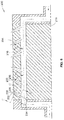
- FIG. 14 is a further embodiment of a roll body 502.
- the flow paths 530 of the vacuum holes 506 are non-linear and have an arcuate path from the inlet 532 to the outlet 534.
- the curvature of the flow paths 530 is such that the portion of the flow paths 530 proximate the outlet 534 is extending in an axial direction in line with the flow of fluid within vacuum passage 516 such that the air exiting the vacuum holes 506 has an axial component to its flow when the air enters the vacuum passage 516.
- the flow of air entering the vacuum holes 506, illustrated by arrow 540 is perpendicular to the central axis 524 of the vacuum passage 516 and rotational axis 518 such that the flow path 530 does not have an axial component proximate the inlet 532 as illustrated by ⁇ 8 .
- the flow path 530 does have an axial component proximate the outlet 534 due to the curvature of the vacuum hole 506. More particularly, the flow path 530 defines an outlet angle ⁇ 9 with central axis 524 and rotational axis 518.
- the vacuum holes 506 of FIG. 14 are illustrated as smooth curves, other embodiments could utilize two straight sections that extend at an angle relative to one another to provide a flow path that has an inlet angle ⁇ 8 that is different than an outlet angle ⁇ 9 such as illustrated in FIG. 18 .
- the outlet angle ⁇ 9 can be less than 10 degrees, even more preferably less than 5 degrees and can also approach being 0 degrees while still providing a small axial footprint for the vacuum holes 506. This allows for even reduced interference of the flow of air within the vacuum passage 516 by the jets of air exiting the vacuum holes 506.
- the curved vacuum hole 506 allow for accommodating the grooves formed in the outer periphery of the roll body 502 which reduce the axial footprint available within which to locate the vacuum holes 506.
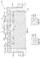
- a further feature of the embodiment of FIG. 14 is that the vacuum holes 506 are formed in inserts 550 that are operably secured to the rest of the roll body 502.
- This arrangement allows for the formation of the complex shape of the vacuum holes 506 to be formed external to the roll body, i.e. not directly machined or otherwise formed into the roll body 502.
- the complexity of the shape of the vacuum holes 506 results in undercuts or regions that cannot be easily machined, if at all.
- the inserts 550 are formed by 3D printing the inserts to include the vacuum hole 506. Further, the inserts could be formed from separate parts that are assembled after formation. This would be particularly true if it were desired to machine the complex vacuum holes. Other forming methods could be implemented such as injection molding, cast, etc.
- the inserts 550 could be formed from metal or plastic materials. In situations where the insert 550 will not contact the web of material or other components of adjacent processing rolls, less durable materials could be used.
- the inserts 550 are removably attached to the rest of the roll body 502 such that they can be replaced for maintenance or to modify the vacuum characteristics of the roll body 502. Further, the use of inserts allows for calibrating the vacuum of a given roll body 502 due to potential manufacturing tolerances and unexpected pressure drops.
- an insert carrier 552 extends over the inserts 550 and operably secures the inserts 550 to the remainder of the roll body 502.
- the carrier 552 in this embodiment forms a portion of the outer periphery 504 against which the web of material is adhered using the vacuum supplied using the vacuum holes 506.
- the outermost portion of the insert could form a portion of the outer periphery of the roll body 502.
- all of the inserts 550 need not have a same shape, angle, size or orientation for the vacuum hole 506 within a given roll body 502 or at a same angular location about the rotational axis 518.
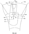
- FIGS. 21-23 illustrate a further embodiment of a processing roll 602 using vacuum holes 606 similar to the vacuum holes 506 described above.
- the flow path 630 of the vacuum holes 606 are curved from the inlet end 632 to the outlet end 634 similar to the embodiment of vacuum hole 506.
- the inlet 632 portion of the flow path 630 is angularly/circumferentially offset from the outlet portion of the flow path 630.
- the flow path 630 is designed to align the flow exiting the outlet 634 with the flow path 624 of the vacuum passage 616 such that the flow path 630 of the jets of air exiting the vacuum hole 606 into the vacuum passage 616 have substantially no circumferential or angular component. This is unlike the embodiment of FIG. 5 .
- This configuration attempts to prevent any swirling of the air within vacuum passage 616 such as illustrated by arrow 660 due to the air jets having a circumferential/radial component when exiting outlet 634.
- the portion of the flow path 630 proximate inlet 632 of the vacuum hole 606 extends at a non-zero ⁇ 1 angle relative to the central axis 624 of the vacuum passage 616.
- the flow path 630 proximate the outlet 634 of the vacuum hole 606 is substantially parallel with the central axis 624 and thus has substantially zero angular/circumferential component such that all air exiting the vacuum hole 606 flows substantially axially toward the end of the roll body 602.
- This embodiment again uses inserts 650 that form, at least, part of the vacuum hole 606 and particularly the complex profile that provides both axial directing of the jets of air towards the vacuum source as well as eliminating any angular component of the air jet due to the inlet 132 being angular offset by angle ⁇ from a line (having reference character 662) passing through the center point 624 of the vacuum flow path and the intersection of the outlet 634 and the vacuum flow path.
- FIGS. 24-28 illustrate the insert 650 removed from the rest of the roll body 602
- test system was prepared. Two test samples of 70 inch PVC pipe were prepared and are illustrated in FIGS. 15 and 16 .
- Each pipe had seven (7) groups of holes with each group of holes including thirteen (13) axially spaced apart holes.
- holes were provided that extend substantially perpendicular to the center of the pipe.
- the holes were drilled at 45 degrees to the center of the pipe.
- a vacuum source was then connected to one end of the pipes and the opposing end was closed off.
- the vacuum was measured at each group of holes.
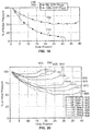
- Three sets of data was collected and illustrated in FIG. 17 .
- the first set of data is for the pipe illustrated in FIG. 15 and is illustrated by the line that includes diamond markers.
- the second set of data is for the pipe illustrated in FIG. 16 with the 45 degree holes with the direction of the flow path of the holes aligned with the direction of flow of air through the pipe, i.e. the holes are directed toward the end of the pipe were the vacuum was supplied.
- This data is represented by the line in FIG. 17 with the square markers.
- a third set of data was gathered where the vacuum was supplied to the opposite end of the pipe of FIG. 16 such that the air exiting the vacuum holes was traveling in a direction extending away from the end to which the vacuum was being supplied. This data is represented by the line in FIG. 17 with the triangular markers.
- FIG. 17 illustrates that there was a 71 % vacuum decrease when the air jets were pushing against the direction of the air flow within the tube, i.e. where the air exiting the vacuum holes was directed in a direction away from the vacuum source.
- FIG. 19 illustrates a further test done to test the effects of angled vacuum holes for use in rolls having an axial length of 135 inches.
- the test fixture was one half of a 135 inch roll and vacuum was applied at one end at 14 inches of mercury.
- the top line that includes the triangles identified with reference character 700 included angled vacuum holes that axially directed the air jets exiting the vacuum holes towards the vacuum source.
- the bottom line identified with reference character 710 had perpendicularly directed vacuum holes that created air jets that were not aligned with the flow of air within the corresponding vacuum passage coupled to the vacuum source.
- FIG. 20 shows the percentage of pressure drop against the position along the roll for different length rolls.
- Line 800 (which is the same as line 700 in FIG. 19 ) simulates 135" roll by being a half of 135" roll but with vacuum supplied at a single end of the roll.
- Each of the other lines represent rolls that are 10 inches shorter by providing a test sample that is 5 inches shorter (i.e. half of the 10 inch increment).
Landscapes
- Rolls And Other Rotary Bodies (AREA)
- Treatment Of Fiber Materials (AREA)
Applications Claiming Priority (2)
| Application Number | Priority Date | Filing Date | Title |
|---|---|---|---|
| US201562206123P | 2015-08-17 | 2015-08-17 | |
| US15/218,502 US10011450B2 (en) | 2015-08-17 | 2016-07-25 | Web processing roll having directional vacuum ports |
Publications (2)
| Publication Number | Publication Date |
|---|---|
| EP3133036A1 true EP3133036A1 (de) | 2017-02-22 |
| EP3133036B1 EP3133036B1 (de) | 2020-10-07 |
Family
ID=56787277
Family Applications (1)
| Application Number | Title | Priority Date | Filing Date |
|---|---|---|---|
| EP16184026.9A Active EP3133036B1 (de) | 2015-08-17 | 2016-08-12 | Bahnverarbeitungswalze mit direktionalen vakuumports |
Country Status (2)
| Country | Link |
|---|---|
| US (1) | US10011450B2 (de) |
| EP (1) | EP3133036B1 (de) |
Families Citing this family (4)
| Publication number | Priority date | Publication date | Assignee | Title |
|---|---|---|---|---|
| US10786946B2 (en) * | 2017-09-13 | 2020-09-29 | Thermwood Corporation | Apparatus and methods for compressing material during additive manufacturing |
| WO2021206591A1 (en) * | 2020-04-06 | 2021-10-14 | Essity Hygiene And Health Aktiebolag | A method for transferring one or more cut-out nonwoven material members for use in an absorbent article |
| US12319533B2 (en) | 2022-10-19 | 2025-06-03 | Bw Converting, Inc. | Fluid delivery system for interfolding apparatus |
| JP2024088903A (ja) * | 2022-12-21 | 2024-07-03 | 京セラドキュメントソリューションズ株式会社 | 搬送ローラー、ウェブ搬送装置、画像形成装置 |
Citations (4)
| Publication number | Priority date | Publication date | Assignee | Title |
|---|---|---|---|---|
| DE2737882A1 (de) * | 1977-08-23 | 1979-03-01 | Voith Gmbh J M | Zylinder fuer maschinen zur herstellung von faserbahnen |
| US4466605A (en) * | 1981-08-07 | 1984-08-21 | Gao Gesellschaft Fur Automation Und Organisation Mbh | Stacking device for sheet material |
| US5913268A (en) * | 1998-02-17 | 1999-06-22 | Xerox Corporation | Pneumatic rollers and paper handling arrangements |
| DE10043855A1 (de) * | 2000-09-06 | 2002-03-14 | Voith Paper Patent Gmbh | Saugwalze |
Family Cites Families (6)
| Publication number | Priority date | Publication date | Assignee | Title |
|---|---|---|---|---|
| US843781A (en) | 1904-12-31 | 1907-02-12 | Seth Wheeler | Apparatus for cutting, folding, and interfolding sheets or units. |
| US4917665A (en) | 1987-06-16 | 1990-04-17 | C. G. Bretting Manufacturing Co. Inc. | Bedroll interfolding machinery improvement |
| EP1415941B1 (de) | 2002-10-31 | 2007-04-11 | M T C - Macchine Trasformazione Carta S.r.l. | Verfahren zum Aktivieren von Sauglöchern von Rollen für papierbearbeitende Maschinen und Rollen zur Ausführung dieses Verfahrens |
| EP1449799A1 (de) | 2003-02-18 | 2004-08-25 | M T C - Macchine Trasformazione Carta S.r.l. | Walze zum Fördern einer Papierbahn oder eines Papierblattes in einer Papierverarbeitungsmaschine und dabei erzieltes Transportverfahren |
| US7533709B2 (en) * | 2005-05-31 | 2009-05-19 | Curt G. Joa, Inc. | High speed vacuum porting |
| US7458927B2 (en) | 2005-10-07 | 2008-12-02 | C.G. Bretting Manufacturing Co., Inc. | Interfolder with pre-forming transfer roll |
-
2016
- 2016-07-25 US US15/218,502 patent/US10011450B2/en active Active
- 2016-08-12 EP EP16184026.9A patent/EP3133036B1/de active Active
Patent Citations (4)
| Publication number | Priority date | Publication date | Assignee | Title |
|---|---|---|---|---|
| DE2737882A1 (de) * | 1977-08-23 | 1979-03-01 | Voith Gmbh J M | Zylinder fuer maschinen zur herstellung von faserbahnen |
| US4466605A (en) * | 1981-08-07 | 1984-08-21 | Gao Gesellschaft Fur Automation Und Organisation Mbh | Stacking device for sheet material |
| US5913268A (en) * | 1998-02-17 | 1999-06-22 | Xerox Corporation | Pneumatic rollers and paper handling arrangements |
| DE10043855A1 (de) * | 2000-09-06 | 2002-03-14 | Voith Paper Patent Gmbh | Saugwalze |
Also Published As
| Publication number | Publication date |
|---|---|
| US20170050816A1 (en) | 2017-02-23 |
| US10011450B2 (en) | 2018-07-03 |
| EP3133036B1 (de) | 2020-10-07 |
Similar Documents
| Publication | Publication Date | Title |
|---|---|---|
| EP3133036B1 (de) | Bahnverarbeitungswalze mit direktionalen vakuumports | |
| CN104455471B (zh) | 用于增加阀中的流体流动的装置及位于阀的流体通道中的阀笼 | |
| US12449063B2 (en) | Fluid flow control devices and systems, and methods of flowing fluids therethrough | |
| EP3009723B1 (de) | Entwurf einer steuerventilverkleidung mit gewundenem pfad | |
| CN102015057B (zh) | 具有粗分离器的空气滤清器 | |
| CN106232199B (zh) | 具有凹陷侧部的过滤元件 | |
| CN108136285B (zh) | 具有卷绕式过滤器滤芯的切向空气净化器 | |
| CN109519580B (zh) | 具有导向叶片的控制阀 | |
| CN208090024U (zh) | 用于流体控制阀的阀体和流体流动控制阀 | |
| US20180280900A1 (en) | Fluid Mixing Device | |
| JP2014507268A (ja) | 新規形状の濾過エレメント | |
| CN103826720B8 (zh) | 多旋流喷雾喷嘴 | |
| CN101208559B (zh) | 燃烧器 | |
| EP3320251B1 (de) | Echtzeit-erosionskontrolle in flüssigkeitsleitungen | |
| KR20240056721A (ko) | 유체 흐름 제어 장치 및 시스템, 및 유체 흐름 방법 | |
| CA2446565C (en) | Vacuum cleaning folding rail | |
| WO2021038513A1 (en) | Flow optimized filter | |
| US20250256339A1 (en) | Rotary cutting tools with through coolant channels | |
| US12173735B2 (en) | Vortex suppression device | |
| JP4399859B2 (ja) | 塗布ヘッド及び塗布装置 | |
| US20070284553A1 (en) | Valve ball guide and seat design | |
| EP3807562A1 (de) | Erosionsbeständige verkleidung für ein ventil |
Legal Events
| Date | Code | Title | Description |
|---|---|---|---|
| PUAI | Public reference made under article 153(3) epc to a published international application that has entered the european phase |
Free format text: ORIGINAL CODE: 0009012 |
|
| STAA | Information on the status of an ep patent application or granted ep patent |
Free format text: STATUS: THE APPLICATION HAS BEEN PUBLISHED |
|
| AK | Designated contracting states |
Kind code of ref document: A1 Designated state(s): AL AT BE BG CH CY CZ DE DK EE ES FI FR GB GR HR HU IE IS IT LI LT LU LV MC MK MT NL NO PL PT RO RS SE SI SK SM TR |
|
| AX | Request for extension of the european patent |
Extension state: BA ME |
|
| STAA | Information on the status of an ep patent application or granted ep patent |
Free format text: STATUS: REQUEST FOR EXAMINATION WAS MADE |
|
| 17P | Request for examination filed |
Effective date: 20170822 |
|
| RBV | Designated contracting states (corrected) |
Designated state(s): AL AT BE BG CH CY CZ DE DK EE ES FI FR GB GR HR HU IE IS IT LI LT LU LV MC MK MT NL NO PL PT RO RS SE SI SK SM TR |
|
| STAA | Information on the status of an ep patent application or granted ep patent |
Free format text: STATUS: EXAMINATION IS IN PROGRESS |
|
| 17Q | First examination report despatched |
Effective date: 20191008 |
|
| GRAP | Despatch of communication of intention to grant a patent |
Free format text: ORIGINAL CODE: EPIDOSNIGR1 |
|
| STAA | Information on the status of an ep patent application or granted ep patent |
Free format text: STATUS: GRANT OF PATENT IS INTENDED |
|
| INTG | Intention to grant announced |
Effective date: 20200708 |
|
| GRAS | Grant fee paid |
Free format text: ORIGINAL CODE: EPIDOSNIGR3 |
|
| GRAA | (expected) grant |
Free format text: ORIGINAL CODE: 0009210 |
|
| STAA | Information on the status of an ep patent application or granted ep patent |
Free format text: STATUS: THE PATENT HAS BEEN GRANTED |
|
| AK | Designated contracting states |
Kind code of ref document: B1 Designated state(s): AL AT BE BG CH CY CZ DE DK EE ES FI FR GB GR HR HU IE IS IT LI LT LU LV MC MK MT NL NO PL PT RO RS SE SI SK SM TR |
|
| REG | Reference to a national code |
Ref country code: GB Ref legal event code: FG4D |
|
| REG | Reference to a national code |
Ref country code: CH Ref legal event code: EP Ref country code: AT Ref legal event code: REF Ref document number: 1320976 Country of ref document: AT Kind code of ref document: T Effective date: 20201015 |
|
| REG | Reference to a national code |
Ref country code: IE Ref legal event code: FG4D |
|
| REG | Reference to a national code |
Ref country code: DE Ref legal event code: R096 Ref document number: 602016045272 Country of ref document: DE |
|
| REG | Reference to a national code |
Ref country code: NL Ref legal event code: MP Effective date: 20201007 |
|
| REG | Reference to a national code |
Ref country code: AT Ref legal event code: MK05 Ref document number: 1320976 Country of ref document: AT Kind code of ref document: T Effective date: 20201007 |
|
| PG25 | Lapsed in a contracting state [announced via postgrant information from national office to epo] |
Ref country code: RS Free format text: LAPSE BECAUSE OF FAILURE TO SUBMIT A TRANSLATION OF THE DESCRIPTION OR TO PAY THE FEE WITHIN THE PRESCRIBED TIME-LIMIT Effective date: 20201007 Ref country code: PT Free format text: LAPSE BECAUSE OF FAILURE TO SUBMIT A TRANSLATION OF THE DESCRIPTION OR TO PAY THE FEE WITHIN THE PRESCRIBED TIME-LIMIT Effective date: 20210208 Ref country code: NO Free format text: LAPSE BECAUSE OF FAILURE TO SUBMIT A TRANSLATION OF THE DESCRIPTION OR TO PAY THE FEE WITHIN THE PRESCRIBED TIME-LIMIT Effective date: 20210107 Ref country code: NL Free format text: LAPSE BECAUSE OF FAILURE TO SUBMIT A TRANSLATION OF THE DESCRIPTION OR TO PAY THE FEE WITHIN THE PRESCRIBED TIME-LIMIT Effective date: 20201007 Ref country code: FI Free format text: LAPSE BECAUSE OF FAILURE TO SUBMIT A TRANSLATION OF THE DESCRIPTION OR TO PAY THE FEE WITHIN THE PRESCRIBED TIME-LIMIT Effective date: 20201007 Ref country code: GR Free format text: LAPSE BECAUSE OF FAILURE TO SUBMIT A TRANSLATION OF THE DESCRIPTION OR TO PAY THE FEE WITHIN THE PRESCRIBED TIME-LIMIT Effective date: 20210108 |
|
| REG | Reference to a national code |
Ref country code: LT Ref legal event code: MG4D |
|
| PG25 | Lapsed in a contracting state [announced via postgrant information from national office to epo] |
Ref country code: ES Free format text: LAPSE BECAUSE OF FAILURE TO SUBMIT A TRANSLATION OF THE DESCRIPTION OR TO PAY THE FEE WITHIN THE PRESCRIBED TIME-LIMIT Effective date: 20201007 Ref country code: AT Free format text: LAPSE BECAUSE OF FAILURE TO SUBMIT A TRANSLATION OF THE DESCRIPTION OR TO PAY THE FEE WITHIN THE PRESCRIBED TIME-LIMIT Effective date: 20201007 Ref country code: BG Free format text: LAPSE BECAUSE OF FAILURE TO SUBMIT A TRANSLATION OF THE DESCRIPTION OR TO PAY THE FEE WITHIN THE PRESCRIBED TIME-LIMIT Effective date: 20210107 Ref country code: LV Free format text: LAPSE BECAUSE OF FAILURE TO SUBMIT A TRANSLATION OF THE DESCRIPTION OR TO PAY THE FEE WITHIN THE PRESCRIBED TIME-LIMIT Effective date: 20201007 Ref country code: SE Free format text: LAPSE BECAUSE OF FAILURE TO SUBMIT A TRANSLATION OF THE DESCRIPTION OR TO PAY THE FEE WITHIN THE PRESCRIBED TIME-LIMIT Effective date: 20201007 Ref country code: PL Free format text: LAPSE BECAUSE OF FAILURE TO SUBMIT A TRANSLATION OF THE DESCRIPTION OR TO PAY THE FEE WITHIN THE PRESCRIBED TIME-LIMIT Effective date: 20201007 Ref country code: IS Free format text: LAPSE BECAUSE OF FAILURE TO SUBMIT A TRANSLATION OF THE DESCRIPTION OR TO PAY THE FEE WITHIN THE PRESCRIBED TIME-LIMIT Effective date: 20210207 |
|
| PG25 | Lapsed in a contracting state [announced via postgrant information from national office to epo] |
Ref country code: HR Free format text: LAPSE BECAUSE OF FAILURE TO SUBMIT A TRANSLATION OF THE DESCRIPTION OR TO PAY THE FEE WITHIN THE PRESCRIBED TIME-LIMIT Effective date: 20201007 |
|
| REG | Reference to a national code |
Ref country code: DE Ref legal event code: R097 Ref document number: 602016045272 Country of ref document: DE |
|
| PG25 | Lapsed in a contracting state [announced via postgrant information from national office to epo] |
Ref country code: EE Free format text: LAPSE BECAUSE OF FAILURE TO SUBMIT A TRANSLATION OF THE DESCRIPTION OR TO PAY THE FEE WITHIN THE PRESCRIBED TIME-LIMIT Effective date: 20201007 Ref country code: CZ Free format text: LAPSE BECAUSE OF FAILURE TO SUBMIT A TRANSLATION OF THE DESCRIPTION OR TO PAY THE FEE WITHIN THE PRESCRIBED TIME-LIMIT Effective date: 20201007 Ref country code: LT Free format text: LAPSE BECAUSE OF FAILURE TO SUBMIT A TRANSLATION OF THE DESCRIPTION OR TO PAY THE FEE WITHIN THE PRESCRIBED TIME-LIMIT Effective date: 20201007 Ref country code: SM Free format text: LAPSE BECAUSE OF FAILURE TO SUBMIT A TRANSLATION OF THE DESCRIPTION OR TO PAY THE FEE WITHIN THE PRESCRIBED TIME-LIMIT Effective date: 20201007 Ref country code: SK Free format text: LAPSE BECAUSE OF FAILURE TO SUBMIT A TRANSLATION OF THE DESCRIPTION OR TO PAY THE FEE WITHIN THE PRESCRIBED TIME-LIMIT Effective date: 20201007 Ref country code: RO Free format text: LAPSE BECAUSE OF FAILURE TO SUBMIT A TRANSLATION OF THE DESCRIPTION OR TO PAY THE FEE WITHIN THE PRESCRIBED TIME-LIMIT Effective date: 20201007 |
|
| PLBE | No opposition filed within time limit |
Free format text: ORIGINAL CODE: 0009261 |
|
| STAA | Information on the status of an ep patent application or granted ep patent |
Free format text: STATUS: NO OPPOSITION FILED WITHIN TIME LIMIT |
|
| PG25 | Lapsed in a contracting state [announced via postgrant information from national office to epo] |
Ref country code: DK Free format text: LAPSE BECAUSE OF FAILURE TO SUBMIT A TRANSLATION OF THE DESCRIPTION OR TO PAY THE FEE WITHIN THE PRESCRIBED TIME-LIMIT Effective date: 20201007 |
|
| 26N | No opposition filed |
Effective date: 20210708 |
|
| PG25 | Lapsed in a contracting state [announced via postgrant information from national office to epo] |
Ref country code: AL Free format text: LAPSE BECAUSE OF FAILURE TO SUBMIT A TRANSLATION OF THE DESCRIPTION OR TO PAY THE FEE WITHIN THE PRESCRIBED TIME-LIMIT Effective date: 20201007 |
|
| PG25 | Lapsed in a contracting state [announced via postgrant information from national office to epo] |
Ref country code: SI Free format text: LAPSE BECAUSE OF FAILURE TO SUBMIT A TRANSLATION OF THE DESCRIPTION OR TO PAY THE FEE WITHIN THE PRESCRIBED TIME-LIMIT Effective date: 20201007 |
|
| REG | Reference to a national code |
Ref country code: CH Ref legal event code: PL |
|
| PG25 | Lapsed in a contracting state [announced via postgrant information from national office to epo] |
Ref country code: MC Free format text: LAPSE BECAUSE OF FAILURE TO SUBMIT A TRANSLATION OF THE DESCRIPTION OR TO PAY THE FEE WITHIN THE PRESCRIBED TIME-LIMIT Effective date: 20201007 |
|
| REG | Reference to a national code |
Ref country code: BE Ref legal event code: MM Effective date: 20210831 |
|
| GBPC | Gb: european patent ceased through non-payment of renewal fee |
Effective date: 20210812 |
|
| PG25 | Lapsed in a contracting state [announced via postgrant information from national office to epo] |
Ref country code: LI Free format text: LAPSE BECAUSE OF NON-PAYMENT OF DUE FEES Effective date: 20210831 Ref country code: CH Free format text: LAPSE BECAUSE OF NON-PAYMENT OF DUE FEES Effective date: 20210831 |
|
| PG25 | Lapsed in a contracting state [announced via postgrant information from national office to epo] |
Ref country code: IS Free format text: LAPSE BECAUSE OF FAILURE TO SUBMIT A TRANSLATION OF THE DESCRIPTION OR TO PAY THE FEE WITHIN THE PRESCRIBED TIME-LIMIT Effective date: 20210207 Ref country code: LU Free format text: LAPSE BECAUSE OF NON-PAYMENT OF DUE FEES Effective date: 20210812 |
|
| PG25 | Lapsed in a contracting state [announced via postgrant information from national office to epo] |
Ref country code: IE Free format text: LAPSE BECAUSE OF NON-PAYMENT OF DUE FEES Effective date: 20210812 Ref country code: GB Free format text: LAPSE BECAUSE OF NON-PAYMENT OF DUE FEES Effective date: 20210812 Ref country code: FR Free format text: LAPSE BECAUSE OF NON-PAYMENT OF DUE FEES Effective date: 20210831 Ref country code: BE Free format text: LAPSE BECAUSE OF NON-PAYMENT OF DUE FEES Effective date: 20210831 |
|
| PG25 | Lapsed in a contracting state [announced via postgrant information from national office to epo] |
Ref country code: HU Free format text: LAPSE BECAUSE OF FAILURE TO SUBMIT A TRANSLATION OF THE DESCRIPTION OR TO PAY THE FEE WITHIN THE PRESCRIBED TIME-LIMIT; INVALID AB INITIO Effective date: 20160812 |
|
| PG25 | Lapsed in a contracting state [announced via postgrant information from national office to epo] |
Ref country code: CY Free format text: LAPSE BECAUSE OF FAILURE TO SUBMIT A TRANSLATION OF THE DESCRIPTION OR TO PAY THE FEE WITHIN THE PRESCRIBED TIME-LIMIT Effective date: 20201007 |
|
| PG25 | Lapsed in a contracting state [announced via postgrant information from national office to epo] |
Ref country code: MK Free format text: LAPSE BECAUSE OF FAILURE TO SUBMIT A TRANSLATION OF THE DESCRIPTION OR TO PAY THE FEE WITHIN THE PRESCRIBED TIME-LIMIT Effective date: 20201007 |
|
| PG25 | Lapsed in a contracting state [announced via postgrant information from national office to epo] |
Ref country code: MT Free format text: LAPSE BECAUSE OF FAILURE TO SUBMIT A TRANSLATION OF THE DESCRIPTION OR TO PAY THE FEE WITHIN THE PRESCRIBED TIME-LIMIT Effective date: 20201007 |
|
| PGFP | Annual fee paid to national office [announced via postgrant information from national office to epo] |
Ref country code: DE Payment date: 20250827 Year of fee payment: 10 |
|
| PGFP | Annual fee paid to national office [announced via postgrant information from national office to epo] |
Ref country code: IT Payment date: 20250820 Year of fee payment: 10 |
|
| PG25 | Lapsed in a contracting state [announced via postgrant information from national office to epo] |
Ref country code: TR Free format text: LAPSE BECAUSE OF FAILURE TO SUBMIT A TRANSLATION OF THE DESCRIPTION OR TO PAY THE FEE WITHIN THE PRESCRIBED TIME-LIMIT Effective date: 20201007 |