EP3133217A1 - Petite panier de wc - Google Patents
Petite panier de wc Download PDFInfo
- Publication number
- EP3133217A1 EP3133217A1 EP16183401.5A EP16183401A EP3133217A1 EP 3133217 A1 EP3133217 A1 EP 3133217A1 EP 16183401 A EP16183401 A EP 16183401A EP 3133217 A1 EP3133217 A1 EP 3133217A1
- Authority
- EP
- European Patent Office
- Prior art keywords
- wall
- holding device
- chambers
- toilet bowl
- front wall
- Prior art date
- Legal status (The legal status is an assumption and is not a legal conclusion. Google has not performed a legal analysis and makes no representation as to the accuracy of the status listed.)
- Withdrawn
Links
Images
Classifications
-
- E—FIXED CONSTRUCTIONS
- E03—WATER SUPPLY; SEWERAGE
- E03D—WATER-CLOSETS OR URINALS WITH FLUSHING DEVICES; FLUSHING VALVES THEREFOR
- E03D9/00—Sanitary or other accessories for lavatories ; Devices for cleaning or disinfecting the toilet room or the toilet bowl; Devices for eliminating smells
- E03D9/02—Devices adding a disinfecting, deodorising, or cleaning agent to the water while flushing
- E03D9/03—Devices adding a disinfecting, deodorising, or cleaning agent to the water while flushing consisting of a separate container with an outlet through which the agent is introduced into the flushing water, e.g. by suction ; Devices for agents in direct contact with flushing water
- E03D9/032—Devices connected to or dispensing into the bowl
-
- E—FIXED CONSTRUCTIONS
- E03—WATER SUPPLY; SEWERAGE
- E03D—WATER-CLOSETS OR URINALS WITH FLUSHING DEVICES; FLUSHING VALVES THEREFOR
- E03D9/00—Sanitary or other accessories for lavatories ; Devices for cleaning or disinfecting the toilet room or the toilet bowl; Devices for eliminating smells
- E03D9/02—Devices adding a disinfecting, deodorising, or cleaning agent to the water while flushing
- E03D2009/024—Devices adding a disinfecting, deodorising, or cleaning agent to the water while flushing using a solid substance
Definitions
- the present invention relates to a holding device and a WC-drug delivery device for mounting in a toilet bowl.
- Such holding devices also known as “toilet bowls" are used to hold chemical compositions which are usually released during a rinsing process at least partially into the rinsing water of the toilet bowl.
- Such compositions are referred to hereinafter as "active ingredients”.
- active ingredients can represent a cleaning agent, but on the other hand also contain other chemical compositions, in particular fragrance compositions that are less in the rinse water, but rather (often preferably exclusively) to the ambient air of the toilet bowl, ie in a toilet room to be discharged.
- the cleaning agent is dispensed into the rinsing water on demand, ie in a rinsing process, while fragrance of a fragrance unit is also continuously released into the ambient air.
- cleaning and fragrance agents are kept in separate chambers in some embodiments known from practice. Examples of this show the WO 2006/013322 A1 or the WO 2015/048657 A1 , However, variants are also known in practice which combine cleaning and fragrancing agents in one composition, ie in an active substance molding in a chamber.
- a device which comprises a front shell and a rear shell, which can be connected to one another and hung together by means of a suspension device in the edge of a toilet bowl.
- the interior of the holding device is subdivided into a plurality of separate receiving areas, namely into a first receiving area for receiving a cleaning agent unit, a second receiving area for receiving a fragrance unit and a third receiving area, again for receiving a cleaning agent unit.
- This division into contiguous receiving areas is realized by folding the front shell and the rear shell together, wherein in each case complementarily arranged webs in the front and the rear shell provide for a subdivision into the three receiving areas.
- the holding device serves as a holder for active ingredient tablets.
- These are preferably designed in the form of polygonal blocks of active substance and are therefore referred to below as such, without limiting the generality to this special shaped body.
- Polygonal is generally polygonal. Thus, explicitly no spherical or cylindrical shapes are included, but in contrast forms such as pyramids, rhombohedron, cuboid and / or cubes.
- the holding device thus absorbs the drug blocks in designated areas. It is hung with a hanger on one edge of a toilet bowl. The suspension device thus keeps it in position during any rinsing operations.
- the holding device For holding the blocks of active substance, the holding device comprises at least three cup chambers, that is, at least one middle and two outer.
- cup chamber describes a small chamber, ie a cavity enclosed by outer walls, with openings distributed in a basket over the surface.
- the terms “cup chamber” and “chamber” are used interchangeably.
- the basket chambers are arranged side by side in a longitudinal direction in the manner of a substantially rectilinear chain.
- a cup chamber is thus lined up in a chain between the adjacent cup chambers and the centers of the Chambers are essentially only shifted in the longitudinal direction.
- "essentially” here means that they optionally have at most a slight curvature, but preferably form a straight line.
- the longitudinal direction is thus defined as an axis through the center points of the basket chambers and is perpendicular to the suspension device.
- the cup chambers are positioned over the suspension device below along the lower edge of the rim of the toilet bowl. They form almost a bowstring to the toilet bowl.
- lower edge here is meant the projection inside the toilet bowl, from which the flushing water emerges, in contrast to the upper edge, on which the toilet seat rests.
- the basket chambers each have a hinged in the toilet bowl in the intended state of the holding device downwardly facing bottom. Furthermore, they each have a front wall which faces away from the nearest wall of the toilet bowl in the state of the holding device suspended as intended in the toilet bowl and which has viewing apertures. These are used to control the consumption level of the drug blocks. The user can thus visually determine through these openings how much active substance is still present.
- the cup chambers comprise a facing in the direction of the suspension ceiling wall, which extends from the front wall to the rear only to a central region above the floor and facing away from the front wall, thus facing the nearest wall of the toilet bowl, rear wall. This is preferably designed with water outlet.
- cup chambers each have a cutout as a water inlet, which extends from the trailing edge of the ceiling wall to the upper edge of the rear wall.
- Two in the chain outside arranged basket chambers each have on their outer sides outer side walls. These connect on just the sides that do not point to the central basket, the bottom, the ceiling wall, the front wall and the rear wall and also extend in the area laterally of the water inlet as a side splash guard. Unlike the embodiments known from practice, is this reduces the water input on the outer sides.
- the basket chambers are thus essentially enclosed on all sides by walls. An exception to this is the cut-out area of the imaginary top edge where the water inlet is located.
- a WC active substance delivery device comprises a holding device according to the invention and, arranged therein, a number of active substance shaped bodies.
- a drug block in a cup chamber, as already stated above.
- the bulk of the water flows through the water inlet into the cup chamber.
- the drug block dissolves its active ingredients over time, especially from the back.
- the front visible side is retained longer, which improves the visual impression.
- the outer sides are further pulled up to reduce the water flowing in from there and designed as a splash guard. Otherwise, especially at the outer sides of the WC active agent delivery device, a greater flow of water occurs, ie.
- the holding device borders on the edge of the toilet bowl, like a bowstring.
- the rinse water in the toilet bowl is usually added centrally from behind and then flows horizontally along the edge along, so that the water surge mainly meets laterally on the basket.
- the outer active ingredient blocks are more uniformly flowed and consumed, so that in particular the form visible from the front is retained longer.
- this has the advantage, in addition to optical advantages, that the drug blocks are completely coincidentally completely worn out and thus can be used more efficiently. Because so the consumer can advantageously conveniently exchange the entire holding device, without having to wait long, possibly all drug residues are solved.
- the basket chambers are formed as a single basket with two connecting the rear wall and the front wall side walls. That means they each have their own walls and are separated from the neighboring baskets. This separation thus takes place by means of an actual distance between adjacent cup chambers and not just like a single large cup through a dividing wall.
- the cup chambers as well as the drug blocks can basically have different shapes and sizes; however, preferred are uniform geometries and dimensions. Because this advantageously simplifies the manufacturing process.
- adjacent individual baskets are preferably connected to each other by a web.
- the webs are preferably arranged in the region of a mean height of the chambers and separate the individual cup chambers from each other.
- the outer side walls of the outside arranged Körbchenschhuntn also extend in the area laterally beyond the water inlet on the rear wall to the ceiling wall and back beyond the ceiling wall to the rear wall. This further limits the lateral entry of water while maintaining the given basket height and thus promotes a uniform removal rate on the sides of the active substance block.
- the rate of removal refers to the rate at which the block of active substance is released and washed away - that is, removed.
- a holding device has at least four in a chain side by side arranged basket chambers, as described above.
- the preferred length of a holding device according to the invention in the longitudinal direction is at least 9 cm, more preferably at least 12 cm. As a result, a wide area of the toilet bowl can be supplied with active substance.
- the basket chambers are each formed as two half-shells. All chambers are thus divided substantially centrally in a vertical and longitudinal cutting plane.
- the webs are divided into two parts at this center plane and connect each other in the longitudinal direction adjacent half shells.
- the half shells are about a film hinge in the range connected to the ground.
- the rear wall of a further example of a holding device according to the invention extends in all central cup chambers from the bottom upwards to the ceiling wall only into a central region of the front wall.
- the rear wall is substantially parallel to the front wall and about half as high as this - preferably 45 to 70%, most preferably 55 to 65%, of the height of the front.
- the rear wall of the outer Körbchenschn extends on a side facing the central Körkchenschn side from the bottom upwards to the ceiling wall only up to a central region of the front wall. Starting from there and rising towards the outside, it continues to extend approximately to, preferably exactly, to the height of the outer side wall.
- this rear wall is parallel to the front wall and begins on the inside in about half as high as the front wall, so preferably as high as in the inner cup chambers, d. H. preferably 45 to 70%, most preferably 55 to 65%, of the height of the front. Then, however, their edge is led up to the area of the upper edge of the side wall, so that the rear wall and side wall preferably complete plan.
- This embodiment additionally reduces the water flow in the outer regions, which in turn further adapts the removal rate between the outer and inner side in the outer active substance blocks.
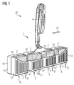
- a holding device 1 This comprises here a suspension device 4 and four lined up in the manner of a linear chain single basket 5, 6 in the form of individual baskets. Two individual baskets are located at the ends of the chain and form the outer individual baskets 6. The other two are arranged between the latter and are thus referred to as inner Einzelkörbchen 5.
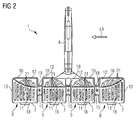
- the suspension device 4 is designed here as a bendable bracket, which can be clamped to a toilet bowl 3. It is fastened via a connecting element to the two middle individual baskets 5.
- the individual baskets 5, 6 are substantially cuboid and thus have 6 side surfaces. All side surfaces are here designed as flat walls, which have only slight rounding in edge areas. In an alternative embodiment, however, they can also be made slightly curved, for example.
- the walls enclose a likewise cuboidal cavity. To define the orientation of the walls is in particular on FIG. 4 referenced; because here is an example of a proper operation of toilet bowl 3 and holding device 1 is shown.
- a ceiling wall 10 has in the direction of the suspension 4. Your opposite is ever a floor 7.
- Your opposite is ever a floor 7.
- the remaining walls are side walls 13, 14, wherein the holding device 1 is closed by the outer side walls 14 to the sides as a unit.
- the front wall 8 has a square surface which has propeller-shaped viewing apertures 9. However, these openings can be designed in any other form. Crucial is only that can be controlled through the viewing openings of the consumption of the active ingredient.
- the top wall 10 extends from the front wall 8 in the direction of the rear wall 11 only approximately to the middle of the individual baskets 5, 6 above the bottom 7.
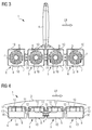
- the rear wall 11 is sufficient in the inner single basket 5 from the bottom 7 upwards to the ceiling wall 10 out only slightly above the height of the center of the front wall 8, z. B. in about 60% of the height. Here it has vertical strips as water outlet openings 21. But equally well, other forms are possible.
- the rear walls of the outer individual baskets 6 start on the insides just as in the inner individual baskets 5 slightly above the height of the center of the basket. However, here the rear wall 11 is guided from the inside to the outside in an arc up to the height of the ceiling wall 10.
- the inner side walls 14 extend in the front half of the individual baskets 5, 6 over their entire height. Towards the rear half, there is a step in the inner side walls 14, so that here they only have slightly more than half the height and thus connect flush to the rear wall 11. This stage does not have the outer side walls 13, they extend completely over the entire height of the outer individual basket 6, so that they also connect flush to the raised rear walls of the outer Einzelkörbchen 6.
- the individual baskets 5, 6 are arranged in the manner of a linear chain. That is, their centers are on a straight line defining a longitudinal direction LR.
- the entire exemplary embodiment has a mirror symmetry to a center plane.
- this center plane denotes a plane running centrally through the device, which plane is perpendicular to the longitudinal direction LR.
- the extension of the device in the longitudinal direction LR is slightly more than 12 cm.
- the individual baskets 5, 6 are additionally designed as half-shells and divided into two parts at a sectional plane in the front half-shell 16 and the rear half-shell 17.
- the cutting plane extends perpendicular to the direction from front wall 8 to rear wall 11 and in the middle of the individual basket 5, 6.
- the webs 15 are also halved by the cutting plane, so that each web half further adjacent single baskets 5, 6 in the longitudinal direction LR together.
- the resulting from front half shell 16 and rear half shell 17 pairs are hingedly connected in the region of the bottom 7 via a film hinge 18. In the closed position, they are secured by locking pins 19 which in the area the webs engage in corresponding detent openings.
- expansion rivets or snaps can be used as a fixture.
- all locking pins can be located on one side, but the pins and openings can also be arranged, for example, alternately.
- An advantage of this design is that it can be manufactured in one piece in an injection molding process. After injection molding, an active substance shaped body 2 can simply be inserted in the production per single basket 5, 6. The half-shells are then folded up and closed over the locks.
- FIG. 1 The individual baskets 5, 6 each contain one of these active ingredient shaped bodies 2, which is embodied here as a rectangular block of active substance with a square base area.
- the drug block can contain a combination of perfume and cleaning agent. Likewise, it is also possible to deposit fragrance and detergent separated in different individual baskets.
- FIG. 1 Overall, an exemplary embodiment of a toilet active ingredient dispensing device 20 according to the invention. In the operating state, it is suspended in a toilet bowl 3, so that it flushes during the rinsing process and thereby the active ingredient blocks contained in the drug is released. Due to the advantageous shape according to the invention, the water flow which is relatively strong in the outer regions of the outer individual cups 6 is reduced. As a result, a more uniform removal rate of the drug blocks is achieved overall, so that their shape is kept as long as possible visually appealing and the drug blocks are completely consumed simultaneously as possible.
Landscapes
- Health & Medical Sciences (AREA)
- Public Health (AREA)
- Epidemiology (AREA)
- Life Sciences & Earth Sciences (AREA)
- Engineering & Computer Science (AREA)
- Hydrology & Water Resources (AREA)
- Water Supply & Treatment (AREA)
- Bidet-Like Cleaning Device And Other Flush Toilet Accessories (AREA)
Applications Claiming Priority (1)
| Application Number | Priority Date | Filing Date | Title |
|---|---|---|---|
| DE102015113834.4A DE102015113834B4 (de) | 2015-08-20 | 2015-08-20 | Haltevorrichtung zu Halterung von Wirkstoffformkörpern in einer Toilettenschüssel mit einer Aufhängevorrichtung sowie WC-Wirkstoffabgabevorrichtung mit dieser Haltevorrichtung |
Publications (1)
| Publication Number | Publication Date |
|---|---|
| EP3133217A1 true EP3133217A1 (fr) | 2017-02-22 |
Family
ID=56618033
Family Applications (1)
| Application Number | Title | Priority Date | Filing Date |
|---|---|---|---|
| EP16183401.5A Withdrawn EP3133217A1 (fr) | 2015-08-20 | 2016-08-09 | Petite panier de wc |
Country Status (2)
| Country | Link |
|---|---|
| EP (1) | EP3133217A1 (fr) |
| DE (1) | DE102015113834B4 (fr) |
Cited By (3)
| Publication number | Priority date | Publication date | Assignee | Title |
|---|---|---|---|---|
| IT201800004015A1 (it) * | 2018-03-27 | 2019-09-27 | Bolton Manitoba S P A | Dispositivo per vasi sanitari con flusso vorticoso interno al dispositivo e relativa tavoletta di prodotto chimico |
| WO2022228817A1 (fr) * | 2021-04-29 | 2022-11-03 | Henkel Ag & Co. Kgaa | Panier pour toilette thermoformé avec dispositif de maintien rigide en flexion |
| WO2022228816A1 (fr) * | 2021-04-29 | 2022-11-03 | Henkel Ag & Co. Kgaa | Cage de bloc de rebord de wc dotée d'un dispositif de retenue à pince |
Citations (7)
| Publication number | Priority date | Publication date | Assignee | Title |
|---|---|---|---|---|
| WO1999024679A1 (fr) * | 1997-11-11 | 1999-05-20 | S.C. Johnson & Son, Inc. | Distributeur |
| WO2006013322A1 (fr) | 2004-08-04 | 2006-02-09 | Reckitt Benckiser Inc | Dispositif de distribution amelioré |
| USD537914S1 (en) * | 2005-07-15 | 2007-03-06 | Reckitt Benckiser Inc. | Dispensing device |
| US20070214555A1 (en) * | 2006-03-14 | 2007-09-20 | Deoflor S.P.A. | Device for dispensing in the flushing water and/or for mixing with the flushing water detergent and/or sanitizing and/or deodorant products, in toilet bowls or hydraulic and sanitary fixtures in general |
| WO2010018006A1 (fr) * | 2008-08-14 | 2010-02-18 | Henkel Ag & Co. Kgaa | Nacelle pour wc, avec élément répartiteur d'eau de chasse |
| WO2015048657A1 (fr) | 2013-09-30 | 2015-04-02 | S. C. Johnson & Son, Inc. | Support de blocs pour rebord de cuvette de toilettes pourvu d'un crochet pivotant |
| US20150167282A1 (en) | 2012-08-22 | 2015-06-18 | Henkel Ag & Co. Kgaa | Toilet cleaner with variable product dispension |
-
2015
- 2015-08-20 DE DE102015113834.4A patent/DE102015113834B4/de not_active Expired - Fee Related
-
2016
- 2016-08-09 EP EP16183401.5A patent/EP3133217A1/fr not_active Withdrawn
Patent Citations (8)
| Publication number | Priority date | Publication date | Assignee | Title |
|---|---|---|---|---|
| WO1999024679A1 (fr) * | 1997-11-11 | 1999-05-20 | S.C. Johnson & Son, Inc. | Distributeur |
| WO2006013322A1 (fr) | 2004-08-04 | 2006-02-09 | Reckitt Benckiser Inc | Dispositif de distribution amelioré |
| USD537914S1 (en) * | 2005-07-15 | 2007-03-06 | Reckitt Benckiser Inc. | Dispensing device |
| US20070214555A1 (en) * | 2006-03-14 | 2007-09-20 | Deoflor S.P.A. | Device for dispensing in the flushing water and/or for mixing with the flushing water detergent and/or sanitizing and/or deodorant products, in toilet bowls or hydraulic and sanitary fixtures in general |
| WO2010018006A1 (fr) * | 2008-08-14 | 2010-02-18 | Henkel Ag & Co. Kgaa | Nacelle pour wc, avec élément répartiteur d'eau de chasse |
| DE102008037723A1 (de) | 2008-08-14 | 2010-02-25 | Henkel Ag & Co. Kgaa | WC-Körbchen mit Spülwasserverteilelement |
| US20150167282A1 (en) | 2012-08-22 | 2015-06-18 | Henkel Ag & Co. Kgaa | Toilet cleaner with variable product dispension |
| WO2015048657A1 (fr) | 2013-09-30 | 2015-04-02 | S. C. Johnson & Son, Inc. | Support de blocs pour rebord de cuvette de toilettes pourvu d'un crochet pivotant |
Cited By (4)
| Publication number | Priority date | Publication date | Assignee | Title |
|---|---|---|---|---|
| IT201800004015A1 (it) * | 2018-03-27 | 2019-09-27 | Bolton Manitoba S P A | Dispositivo per vasi sanitari con flusso vorticoso interno al dispositivo e relativa tavoletta di prodotto chimico |
| WO2019186247A1 (fr) * | 2018-03-27 | 2019-10-03 | Bolton Manitoba S.P.A. | Dispositif pour cuvettes d'équipements sanitaires ayant un écoulement en vortex à l'intérieur du dispositif et comprimé de produit chimique associé |
| WO2022228817A1 (fr) * | 2021-04-29 | 2022-11-03 | Henkel Ag & Co. Kgaa | Panier pour toilette thermoformé avec dispositif de maintien rigide en flexion |
| WO2022228816A1 (fr) * | 2021-04-29 | 2022-11-03 | Henkel Ag & Co. Kgaa | Cage de bloc de rebord de wc dotée d'un dispositif de retenue à pince |
Also Published As
| Publication number | Publication date |
|---|---|
| DE102015113834A1 (de) | 2017-02-23 |
| DE102015113834B4 (de) | 2017-08-24 |
Similar Documents
| Publication | Publication Date | Title |
|---|---|---|
| EP3002375B1 (fr) | Bloc pour rebord de cuvette de w.c. dotée d'un élément de distribution d'eau de rinçage | |
| DE602004003101T2 (de) | Am rand eines toilettenbeckens angebrachte vorrichtung zur abgabe von zwei flüssigkeiten | |
| EP2620489B1 (fr) | Dispositif de distribution d'agent actif et procédé de fabrication d'un dispositif de distribution d'agent actif | |
| DE102013105316A1 (de) | Haltevorrichtung und Spülvorrichtung zur Anbringung in einer Toilettenschüssel und Herstellung derselben Spülvorrichtung | |
| WO2014029510A1 (fr) | Panier pour toilettes à débit de produit variable | |
| DE202018006705U1 (de) | Spültoilette | |
| EP0878586A2 (fr) | Distributeur pour cuvette de toilette | |
| DE102008003359A1 (de) | Abgabevorrichtung zur Abgabe wenigstens eines Wirkstofffluids in das Spülwasser eines Toilettenbeckens sowie zur Beduftung der Umgebung | |
| DE102015113834B4 (de) | Haltevorrichtung zu Halterung von Wirkstoffformkörpern in einer Toilettenschüssel mit einer Aufhängevorrichtung sowie WC-Wirkstoffabgabevorrichtung mit dieser Haltevorrichtung | |
| EP3170940A1 (fr) | Douche-wc comprenant un chauffe-eau | |
| EP0446795A1 (fr) | Dispositif de dosage pour un agent activable par l'eau | |
| EP1799921B1 (fr) | Couvercle de toilette avec un distributeur | |
| EP2620490B1 (fr) | Dispositif de distribution d'agent actif et procédé de fabrication d'un dispositif de distribution d'agent actif | |
| EP3477010B1 (fr) | Petit panier de wc et système de rinçage de wc | |
| DE20023677U1 (de) | Abgabevorrichtung für die Abgabe eines Wirkstoffs | |
| DE102005061974B3 (de) | Sanitäre Wasserauslaufarmatur | |
| DE202013102261U1 (de) | Haltevorrichtung und Spülvorrichtung zur Anbringung in einer Toilettenschüssel | |
| EP3109367A1 (fr) | Dispositif de reception d'un moyen de nettoyage de toilettes | |
| EP3628726A1 (fr) | Bloc désodorisant pour wc comprenant deux compositions différentes | |
| CH645689A5 (en) | Container which is to be arranged in the WC bowl and has cleaning agents and fragrancing means and, in addition, deodorisers and/or disinfecting agents in element form | |
| DE69822754T2 (de) | Kühlschrank mit Zellen zum Herstellen von Eiswürfeln | |
| DE10114195B4 (de) | Sanitäre Duscheinrichtung | |
| DE3738554A1 (de) | Wc-automat zur abgabe einer wirkstoffloesung nach jeder toilettenspuelung | |
| EP1605807B1 (fr) | Dispositif delivrant au moins une substance soluble dans l'eau a une brosse de nettoyage | |
| DE9310224U1 (de) | Dosiervorrichtung |
Legal Events
| Date | Code | Title | Description |
|---|---|---|---|
| PUAI | Public reference made under article 153(3) epc to a published international application that has entered the european phase |
Free format text: ORIGINAL CODE: 0009012 |
|
| AK | Designated contracting states |
Kind code of ref document: A1 Designated state(s): AL AT BE BG CH CY CZ DE DK EE ES FI FR GB GR HR HU IE IS IT LI LT LU LV MC MK MT NL NO PL PT RO RS SE SI SK SM TR |
|
| AX | Request for extension of the european patent |
Extension state: BA ME |
|
| 17P | Request for examination filed |
Effective date: 20170811 |
|
| RBV | Designated contracting states (corrected) |
Designated state(s): AL AT BE BG CH CY CZ DE DK EE ES FI FR GB GR HR HU IE IS IT LI LT LU LV MC MK MT NL NO PL PT RO RS SE SI SK SM TR |
|
| 17Q | First examination report despatched |
Effective date: 20180109 |
|
| GRAP | Despatch of communication of intention to grant a patent |
Free format text: ORIGINAL CODE: EPIDOSNIGR1 |
|
| INTG | Intention to grant announced |
Effective date: 20191111 |
|
| GRAJ | Information related to disapproval of communication of intention to grant by the applicant or resumption of examination proceedings by the epo deleted |
Free format text: ORIGINAL CODE: EPIDOSDIGR1 |
|
| INTC | Intention to grant announced (deleted) | ||
| GRAP | Despatch of communication of intention to grant a patent |
Free format text: ORIGINAL CODE: EPIDOSNIGR1 |
|
| STAA | Information on the status of an ep patent application or granted ep patent |
Free format text: STATUS: GRANT OF PATENT IS INTENDED |
|
| INTG | Intention to grant announced |
Effective date: 20200512 |
|
| STAA | Information on the status of an ep patent application or granted ep patent |
Free format text: STATUS: THE APPLICATION IS DEEMED TO BE WITHDRAWN |
|
| 18D | Application deemed to be withdrawn |
Effective date: 20200923 |