EP3133323A1 - Pilotventilanordnung - Google Patents
Pilotventilanordnung Download PDFInfo
- Publication number
- EP3133323A1 EP3133323A1 EP15181396.1A EP15181396A EP3133323A1 EP 3133323 A1 EP3133323 A1 EP 3133323A1 EP 15181396 A EP15181396 A EP 15181396A EP 3133323 A1 EP3133323 A1 EP 3133323A1
- Authority
- EP
- European Patent Office
- Prior art keywords
- pilot valve
- spindle
- arrangement
- presetting
- presetting mechanism
- Prior art date
- Legal status (The legal status is an assumption and is not a legal conclusion. Google has not performed a legal analysis and makes no representation as to the accuracy of the status listed.)
- Withdrawn
Links
- 230000007246 mechanism Effects 0.000 claims abstract description 84
- 230000008878 coupling Effects 0.000 claims abstract description 28
- 238000010168 coupling process Methods 0.000 claims abstract description 28
- 238000005859 coupling reaction Methods 0.000 claims abstract description 28
- 239000012528 membrane Substances 0.000 claims description 30
- 239000012530 fluid Substances 0.000 claims description 28
- 238000012423 maintenance Methods 0.000 abstract description 5
- 230000008901 benefit Effects 0.000 description 2
- 230000008859 change Effects 0.000 description 2
- 230000007257 malfunction Effects 0.000 description 2
- 239000003507 refrigerant Substances 0.000 description 2
- 230000004075 alteration Effects 0.000 description 1
- 230000026058 directional locomotion Effects 0.000 description 1
- 230000033001 locomotion Effects 0.000 description 1
- 238000005057 refrigeration Methods 0.000 description 1
- 239000000126 substance Substances 0.000 description 1
Images



Classifications
-
- F—MECHANICAL ENGINEERING; LIGHTING; HEATING; WEAPONS; BLASTING
- F16—ENGINEERING ELEMENTS AND UNITS; GENERAL MEASURES FOR PRODUCING AND MAINTAINING EFFECTIVE FUNCTIONING OF MACHINES OR INSTALLATIONS; THERMAL INSULATION IN GENERAL
- F16K—VALVES; TAPS; COCKS; ACTUATING-FLOATS; DEVICES FOR VENTING OR AERATING
- F16K17/00—Safety valves; Equalising valves, e.g. pressure relief valves
- F16K17/02—Safety valves; Equalising valves, e.g. pressure relief valves opening on surplus pressure on one side; closing on insufficient pressure on one side
- F16K17/04—Safety valves; Equalising valves, e.g. pressure relief valves opening on surplus pressure on one side; closing on insufficient pressure on one side spring-loaded
- F16K17/06—Safety valves; Equalising valves, e.g. pressure relief valves opening on surplus pressure on one side; closing on insufficient pressure on one side spring-loaded with special arrangements for adjusting the opening pressure
-
- F—MECHANICAL ENGINEERING; LIGHTING; HEATING; WEAPONS; BLASTING
- F16—ENGINEERING ELEMENTS AND UNITS; GENERAL MEASURES FOR PRODUCING AND MAINTAINING EFFECTIVE FUNCTIONING OF MACHINES OR INSTALLATIONS; THERMAL INSULATION IN GENERAL
- F16K—VALVES; TAPS; COCKS; ACTUATING-FLOATS; DEVICES FOR VENTING OR AERATING
- F16K15/00—Check valves
- F16K15/02—Check valves with guided rigid valve members
- F16K15/025—Check valves with guided rigid valve members the valve being loaded by a spring
-
- F—MECHANICAL ENGINEERING; LIGHTING; HEATING; WEAPONS; BLASTING
- F16—ENGINEERING ELEMENTS AND UNITS; GENERAL MEASURES FOR PRODUCING AND MAINTAINING EFFECTIVE FUNCTIONING OF MACHINES OR INSTALLATIONS; THERMAL INSULATION IN GENERAL
- F16K—VALVES; TAPS; COCKS; ACTUATING-FLOATS; DEVICES FOR VENTING OR AERATING
- F16K27/00—Construction of housing; Use of materials therefor
- F16K27/02—Construction of housing; Use of materials therefor of lift valves
-
- F—MECHANICAL ENGINEERING; LIGHTING; HEATING; WEAPONS; BLASTING
- F16—ENGINEERING ELEMENTS AND UNITS; GENERAL MEASURES FOR PRODUCING AND MAINTAINING EFFECTIVE FUNCTIONING OF MACHINES OR INSTALLATIONS; THERMAL INSULATION IN GENERAL
- F16K—VALVES; TAPS; COCKS; ACTUATING-FLOATS; DEVICES FOR VENTING OR AERATING
- F16K27/00—Construction of housing; Use of materials therefor
- F16K27/02—Construction of housing; Use of materials therefor of lift valves
- F16K27/029—Electromagnetically actuated valves
-
- F—MECHANICAL ENGINEERING; LIGHTING; HEATING; WEAPONS; BLASTING
- F16—ENGINEERING ELEMENTS AND UNITS; GENERAL MEASURES FOR PRODUCING AND MAINTAINING EFFECTIVE FUNCTIONING OF MACHINES OR INSTALLATIONS; THERMAL INSULATION IN GENERAL
- F16K—VALVES; TAPS; COCKS; ACTUATING-FLOATS; DEVICES FOR VENTING OR AERATING
- F16K31/00—Actuating devices; Operating means; Releasing devices
- F16K31/02—Actuating devices; Operating means; Releasing devices electric; magnetic
- F16K31/04—Actuating devices; Operating means; Releasing devices electric; magnetic using a motor
-
- F—MECHANICAL ENGINEERING; LIGHTING; HEATING; WEAPONS; BLASTING
- F16—ENGINEERING ELEMENTS AND UNITS; GENERAL MEASURES FOR PRODUCING AND MAINTAINING EFFECTIVE FUNCTIONING OF MACHINES OR INSTALLATIONS; THERMAL INSULATION IN GENERAL
- F16K—VALVES; TAPS; COCKS; ACTUATING-FLOATS; DEVICES FOR VENTING OR AERATING
- F16K31/00—Actuating devices; Operating means; Releasing devices
- F16K31/02—Actuating devices; Operating means; Releasing devices electric; magnetic
- F16K31/06—Actuating devices; Operating means; Releasing devices electric; magnetic using a magnet, e.g. diaphragm valves, cutting off by means of a liquid
- F16K31/08—Actuating devices; Operating means; Releasing devices electric; magnetic using a magnet, e.g. diaphragm valves, cutting off by means of a liquid using a permanent magnet
- F16K31/086—Actuating devices; Operating means; Releasing devices electric; magnetic using a magnet, e.g. diaphragm valves, cutting off by means of a liquid using a permanent magnet the magnet being movable and actuating a second magnet connected to the closing element
- F16K31/088—Actuating devices; Operating means; Releasing devices electric; magnetic using a magnet, e.g. diaphragm valves, cutting off by means of a liquid using a permanent magnet the magnet being movable and actuating a second magnet connected to the closing element the movement of the first magnet being a rotating or pivoting movement
-
- F—MECHANICAL ENGINEERING; LIGHTING; HEATING; WEAPONS; BLASTING
- F16—ENGINEERING ELEMENTS AND UNITS; GENERAL MEASURES FOR PRODUCING AND MAINTAINING EFFECTIVE FUNCTIONING OF MACHINES OR INSTALLATIONS; THERMAL INSULATION IN GENERAL
- F16K—VALVES; TAPS; COCKS; ACTUATING-FLOATS; DEVICES FOR VENTING OR AERATING
- F16K31/00—Actuating devices; Operating means; Releasing devices
- F16K31/02—Actuating devices; Operating means; Releasing devices electric; magnetic
- F16K31/06—Actuating devices; Operating means; Releasing devices electric; magnetic using a magnet, e.g. diaphragm valves, cutting off by means of a liquid
- F16K31/10—Actuating devices; Operating means; Releasing devices electric; magnetic using a magnet, e.g. diaphragm valves, cutting off by means of a liquid with additional mechanism between armature and closure member
Definitions
- the present invention relates to a pilot valve arrangement
- a pilot valve device which comprises a pilot valve element, a pilot valve seat cooperating with the pilot valve element, and a presetting mechanism for presetting an opening pressure of the pilot valve element
- the pilot valve arrangement further comprising a presetting mechanism actuating device which comprises an actuator element adapted to create an actuating force in order to actuate the presetting mechanism in the pilot valve device so as to preset the opening pressure.
- the invention relates to the pilot valve device comprising the pilot valve element, the pilot valve seat cooperating with the pilot valve element, and the presetting mechanism for presetting the opening pressure of the pilot valve element.
- US 7,669,609 B2 discloses a universal valve for refrigeration systems.
- the universal valve comprises an adapter plate configured to cause the universal valve to function with a stepping motor connected to a pilot regulator stem for pressure setting alterations. As the motor rotates, it can control a regulator pressure setting.
- the object of the invention is solved by the pilot valve arrangement as described in the outset in that the pilot valve arrangement comprises a contactless force coupling arrangement adapted to transfer the actuating force from the presetting mechanism actuating device to the pilot valve device.
- the improved serviceability of the pilot valve arrangement is established. This may for example allow for a quicker or safer maintenance of the pilot valve arrangement.
- presetting the opening pressure means that the presetting mechanism is adapted to adjustably predetermine an opening force to be provided by a pilot fluid in order to open the pilot valve element.
- the pilot valve element will allow the pilot fluid to pass the pilot valve device.
- the actuating force is a torque and the contactless force coupling arrangement comprises cooperating magnets in order to transfer the torque over an air gap.
- the torque preferably is transferred over the air gap present between the cooperating magnets. This allows easy and comfortable torque transfer from the presetting mechanism actuating device to the pilot valve device while no mechanical contact such as a friction fit or mechanical interlocking is necessary to transfer the torque.
- the presetting mechanism actuating device comprises a rotatable axis drivable by the actuator element
- the presetting mechanism comprises a rotatable spindle drivable by the axis
- the contactless force coupling arrangement is adapted to transfer the actuating force from the axis to the spindle so as to rotate the spindle in order to actuate the presetting mechanism.
- the axis and the spindle are spaced apart from each other, by an air gap, for example, the spindle can be rotated by the axis due to the contactless force coupling arrangement. This allows actuating the presetting mechanism despite no mechanical link connecting the axis and the spindle.
- the spindle comprises a first spindle end and the axis provides a cavity adapted to house the first spindle end in order to transfer the actuating force from the actuator element to the presetting mechanism via the contactless force coupling arrangement.
- the cavity at least partially surrounds a circumferential line of the first spindle end.
- the cavity may have a hat-like design. In this case, it is preferred that the air gap is provided between an inner surface of the cavity and the spindle.
- the first spindle end comprises one or more spindle magnets being rotationally fixed relative to the spindle
- the axis comprises a first axis end
- the first axis end comprises one or more axis magnets being rotationally fixed relatively to the axis
- the spindle magnet being a first permanent magnet
- the axis magnet being a second permanent magnet
- the first permanent magnet and the second permanent magnet together being cooperating magnets in order to exert a magnetic force on each other so as to allow the axis to rotate the spindle.
- the one or more spindle magnets are arranged at the circumferential line of the first spindle end.
- the one or more axis magnets are arranged on the inner surface of the cavity.
- the actuating force can be transferred to the presetting mechanism.
- the pilot valve device comprises a bearing in order to facilitate rotation of the spindle magnet.
- a bearing will also facilitate rotation of the spindle itself.
- a preferred bearing is a ball bearing.
- Another preferred bearing is a sleeve bearing.
- the pilot valve element is a membrane, the membrane being biased so as to keep pilot valve element in contact with the pilot valve seat, the presetting mechanism influencing the biasing of the membrane by means of the actuating force and by this presetting the opening pressure.
- the pilot valve element is a double membrane. A higher number of membranes is present in some embodiments though. It is then preferred that three or four membranes are provided. This allows for an increased safety. When the pilot fluid surpasses the opening pressure, the membrane will lift off the pilot valve seat and will allow passing of the pilot fluid.
- the presetting mechanism further comprises a nut, the nut being drivable by means of the actuating force, and a spring, the spring biasing the membrane, and the nut being adapted to pretension a spring depending on a position of the nut.
- the nut coaxially surrounds a spindle. It is preferred that the nut and the spindle comprise cooperating threads so that the nut can move along the spindle when the spindle rotates. To facilitate this, it is preferred that the nut has a nose that assures a movement of the nut along the spindle when the spindle is rotated.
- the actuator element drives the spindle via the axis, the nut will change its position along the spindle and thus change the pretension of the spring. By this, the opening pressure of the pilot valve element can be preset and adjusted.
- the spring is a coil spring and the spring comprises a first spring end and a second spring end, the first spring end being seated on the nut and the second spring end being seated adjacent to the membrane. Accordingly, it is preferred that the spring coaxially surrounds the spindle.
- the spring is seated directly on the membrane.
- the spring is seated on an intermediate element, although still adjacent to the membrane, and the intermediate element transfers the pressure to the membrane.
- the actuator element is a motor.
- the actuator element is an electric motor. Then more preferred electric motors are a continuous motor or a stepper motor.
- the presetting mechanism actuating device may comprise a battery seating or a power socket for attaching a power cable. Furthermore, the presetting mechanism actuating device may comprise one or more buttons and a display to set the actuator element.
- the pilot valve device and the presetting mechanism actuating device comprise a fixing arrangement for fixing the pilot valve device and the presetting mechanism actuating device to each other.
- the fixing arrangement allows for removably fixing the pilot valve device and the actuating device to each other.
- having the fixing arrangement which allows separating the pilot valve device from the presetting mechanism actuating device allows easy replacement of the presetting mechanism actuating device, for example in case of malfunction.
- the presetting mechanism actuating device may easily be replaced or the presetting mechanism can even be actuated by a free magnet in case the contactless force coupling arrangement makes use of cooperating magnets.
- a preferred fixing arrangement is a threaded connection.
- the contactless force coupling arrangement is hermetically sealed on the side of the pilot valve device.
- This embodiment is very much preferred when the pilot valve device and the presetting mechanism actuating device are fixed to each other removably.
- the pilot valve device is hermetically sealed with respect to the contactless force coupling arrangement no pilot fluid can unexpectedly leave the valve nor can any external substance enter the valve through the contactless force coupling arrangement. Nonetheless, the transfer of force is still possible.
- the presetting mechanism comprising the spindle, the nut, the spring and the membrane may be hermetically housed inside the pilot valve device.
- the pilot valve device has a pilot fluid inlet, a pilot fluid outlet, and a main valve connection arrangement in order to connect the pilot valve device to a main valve device such as to control the opening of the main valve device by supplying a pilot fluid to the main valve device passing the pilot valve element and through the pilot fluid outlet. It is preferred that the pilot fluid enters the pilot valve device through the pilot fluid inlet.
- the described design of the pilot valve device is well tested and thus allows a good control of the opening of the main valve device depending on the pilot fluid passing through the pilot valve element.
- the object of the invention is furthermore solved by the pilot valve device as described in the outset, the presetting mechanism being adapted to receive the actuating force via the contactless force coupling arrangement.
- Preferred embodiments of this pilot valve device were already described above in view of the pilot valve arrangement. The same advantages may be reached with the pilot valve device according to the invention.
- Fig. 1 shows the perspective view of the pilot valve arrangement 1 according to an embodiment of the invention.
- the pilot valve arrangement 1 comprises the pilot valve device 2 and the presetting mechanism actuating device 3.
- the presetting mechanism actuating device 3 comprises sockets 4a, 4b for connecting data cables and power cables to the presetting mechanism actuating device 3.
- the presetting mechanism actuating device 3 comprises the display 5 and buttons 6a, 6b, 6c. This way, settings of the presetting mechanism actuating device 3 may be read out or changed.
- the pilot valve device 2 and the presetting mechanism actuating device 3 comprise the fixing arrangement 7 for fixing the pilot valve device 2 and the presetting mechanism actuating device 3 to each other.
- the fixing arrangement 7 is adapted to fix the pilot valve device 2 and the presetting mechanism actuating device 3 removably to each other.
- screws 8a, 8b are present at the fixing arrangement 7.
- the pilot valve device 2 and the presetting mechanism actuating device 3 are separate parts which may be removed from each other by removing the screws 8a, 8b and then pulling off presetting mechanism actuating device 3 from the pilot valve device 2.
- the pilot valve device 2 comprises a main valve connection arrangement 9. In the shown embodiment this main valve connection arrangement 9 is a keyed connection to ensure proper connectability.
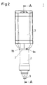
- Fig. 2 shows a side view of the pilot valve arrangement 1. Again it can be seen that the pilot valve device 2 and the presetting mechanism actuating device 3 are fixed to each other via the fixing arrangement 7 which makes use of screws 8a, 8b for fixing the pilot valve device 2 and the presetting mechanism actuating device 3 removably to each other. As laid out earlier, this allows for quick and safe arrangement of the presetting mechanism actuating device 3 in case of malfunction.
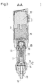
- Fig. 3 now shows a longitudinal section of the view given in fig. 2 .
- the pilot valve device 2 comprises the presetting mechanism comprising the spindle 10, the nut 11 and the spring 12.
- the presetting mechanism is adapted for presetting the opening pressure of the pilot valve element 13 which is also comprised in the pilot valve device 2.
- the pilot valve element 13 in this embodiment is the membrane, the membrane being biased so as to keep the pilot valve element 13 in contact with the pilot valve seat 14, the presetting mechanism influencing the biasing of the membrane.
- the pilot valve device 2 comprises the pilot fluid inlet 15 and the pilot fluid outlet 16 which are arranged adjacent to the main valve connection arrangement 9.
- Fig. 3 also shows that the presetting mechanism actuating device 3 comprises the actuator element 17 adapted to create the actuating force in order to actuate the presetting mechanism in the pilot valve device 2 so as to preset the opening pressure.
- the actuator element 17 is the motor, more specifically the stepper motor. This allows a step by step presetting, thus adjustment, of the opening pressure of the pilot valve element 13.
- the presetting mechanism actuating device 3 furthermore comprises a rotatable axis 18 drivable by the actuator element 17.
- the contactless force coupling arrangement is adapted to transfer the actuating force from the axis 18 to the spindle 10 so as to rotate the spindle 10 in order to actuate the presetting mechanism.
- the actuating force is the rotational torque.
- the design of the contactless force coupling arrangement is shown in more detail in fig. 4 .
- the spindle 10 comprises a first spindle end and the axis 18 provides the cavity 19 adapted to house the first spindle end in order to transfer the actuating force from the actuator element 17 to the presetting mechanism via the contactless force coupling arrangement.
- the contactless force coupling arrangement is adapted to transfer the actuating force from the axis 18 to the spindle 10 so as to rotate the spindle in order to actuate the presetting mechanism.
- the contactless force coupling arrangement comprises cooperating magnets in order to transfer the torque over the air gap 22a, 22b. More specifically, the first spindle end comprises one or more spindle magnets being rotationally fixed relative to the spindle 10, the axis 18 comprises the first axis end, the first axis end comprises one or more axis magnets being rotationally fixed relative to the axis, the spindle magnet in this case being the first permanent magnet 20 and the axis magnet being the second permanent magnet 21.
- the first permanent magnet 20 and the second permanent magnet 21 together are cooperating magnets in order to exert the magnetic force on each other so as to allow the axis 18 to rotate the spindle 10.
- the first permanent magnet 20 is arranged on the circumferential line of the spindle 10 while the second permanent magnet 21 is arranged on the inner surface of the cavity 19.
- the first permanent magnet 20 and the second permanent magnet 21 are arranged such that their respective magnetic fields interlock with each other the magnetic force bridging the air gap 22a, 22b will result in a forced rotation of the spindle 10 once the axis 18 is driven by the presetting mechanism actuating device 3.
- the first spindle end comprising the first permanent magnet 20 is seated on the bearing 23.
- the bearing 23 is seated between the first spindle end and the nut 11.
- the bearing 23 is the ball bearing.
- the nut 11 comprises the nose 24.
- Nose 24 guarantees that nut 11 will start to move along the spindle 10 when spindle 10 is actuated by the actuator element 17. This is due to the fact that nut 11 and spindle 10 are connected to each other via cooperating threads, nut 11 coaxially surrounding spindle 10.
- the spring 12 is the coil spring and the spring 12 comprises the first spring end and the second spring end, the first spring end being seated on the nut 11 and the second spring end being seated adjacent to the pilot valve element 13, thus in this case the membrane.
- the spring 12 coaxially surrounds the spindle 10.
- the spring 12 is biasing in the membrane and the nut 11 is adapted to pretension the spring 12 depending on the position of the nut 11.
- the contactless force coupling arrangement adapted to transfer the actuating force from the presetting mechanism actuating device 3 to the pilot valve device 2 works as follows: the actuator element 17 present in the presetting mechanism actuating device 3 is switched on. Then, the actuator element 17 creates the actuating force in order to actuate the presetting mechanism in the pilot valve device 2 so as to preset the opening pressure. The actuating force is transferred from the actuator element 17 to the axis 18.
- axis 18 and the cavity 19 at the first axis end start to rotate.
- the cavity 19 is adapted to house the first spindle end in order to transfer the actuating force to the presetting mechanism.
- the first permanent magnet 20 and the second permanent magnet 21 by their magnetic fields bridge the air gap 22a, 22b. Due to that the rotational torque of axis 18 can be transferred to the spindle 10.
- spindle 10 starts to rotate nut 11 starts to move along the spindle 10 due to the nut 11 being held at the spindle 10 via the threading and the presence of nose 24 present at nut 11.
- Nut 11 being drivable by means of the actuating force along the spindle 10 will then compress spring 12, thus pretension it, and the second spring end being seated adjacent to the membrane will bias the membrane towards the pilot valve seat 14.
- the presetting mechanism actuating device 3 is adapted to preset the opening pressure of the pilot valve device 2.
- the contactless force coupling arrangement is hermetically sealed on the side of the pilot valve device 2.
- a presetting mechanism housing 25 is present which shields the spindle 10 and the first permanent magnet 20 from the cavity 19.
- the presetting mechanism housing 25 shields the presetting mechanism from the environment and vice versa.
- a wall of the presetting mechanism housing 25 for this reason separates the air gap 22a, 22b in two parts, one between the cavity 19 and the presetting mechanism housing 25 and one between the presetting mechanism housing 25 and the first spindle end carrying the first permanent magnet 20.
- Fig. 5 shows in more detail the pilot valve element 13 and the pilot valve seat 14 according to the given embodiment of the inventive pilot valve arrangement 1.
- spring 12 has the second spring end being seated adjacent to the membrane but not directly on the membrane. Instead, an intermediate element 26 is provided which is interposed between the spring 12 and the pilot valve element 13, in this case, the double membrane. The intermediate element 26 ensures an even distribution of the force exerted by the spring 12.
- the pilot valve element 13 lifts from the pilot valve seat 14 and the pilot fluid, for example a refrigerant, can pass the pilot valve element 13 and through the pilot fluid outlet 16. This way the pilot fluid may pass to a main valve device 27 when the pilot valve device 2 is connected to the main valve device 27 such as to control the opening of the main valve device by supplying the pilot fluid.
- the pilot fluid for example a refrigerant
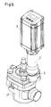
- Fig. 6 shows such a situation.
- the pilot valve device 2 is connected to the main valve device 27 by the main valve connection arrangement 9.
- the pilot valve arrangement 1 then works in the following manner: the opening pressure of the pilot valve device 2 determines at which pressure the main valve device 27 opens.
- the opening pressure is determined by the pressure difference over the double membrane at a lower part of the pilot valve device 2 and the force exerted by the spring 12.
- the pilot fluid for example the refrigerant, enters the pilot valve device 2 via the pilot fluid inlet 15 and exerts an upwards force, which is counteracted by the force exerted by the spring 12 and the pressure in the pilot valve device 2 above the spring 12.
- the fig. 1 to 6 also show the pilot valve device 2 in which the presetting mechanism is adapted to receive the actuating force via the contactless force coupling arrangement according to the invention.
Landscapes
- Engineering & Computer Science (AREA)
- General Engineering & Computer Science (AREA)
- Mechanical Engineering (AREA)
- Physics & Mathematics (AREA)
- Electromagnetism (AREA)
- Mechanically-Actuated Valves (AREA)
Priority Applications (3)
| Application Number | Priority Date | Filing Date | Title |
|---|---|---|---|
| EP15181396.1A EP3133323A1 (de) | 2015-08-18 | 2015-08-18 | Pilotventilanordnung |
| PCT/EP2016/061872 WO2017028974A1 (en) | 2015-08-18 | 2016-05-26 | Pilot valve arrangement |
| US15/743,322 US10443750B2 (en) | 2015-08-18 | 2016-05-26 | Pilot valve arrangement |
Applications Claiming Priority (1)
| Application Number | Priority Date | Filing Date | Title |
|---|---|---|---|
| EP15181396.1A EP3133323A1 (de) | 2015-08-18 | 2015-08-18 | Pilotventilanordnung |
Publications (1)
| Publication Number | Publication Date |
|---|---|
| EP3133323A1 true EP3133323A1 (de) | 2017-02-22 |
Family
ID=53871986
Family Applications (1)
| Application Number | Title | Priority Date | Filing Date |
|---|---|---|---|
| EP15181396.1A Withdrawn EP3133323A1 (de) | 2015-08-18 | 2015-08-18 | Pilotventilanordnung |
Country Status (3)
| Country | Link |
|---|---|
| US (1) | US10443750B2 (de) |
| EP (1) | EP3133323A1 (de) |
| WO (1) | WO2017028974A1 (de) |
Cited By (1)
| Publication number | Priority date | Publication date | Assignee | Title |
|---|---|---|---|---|
| DE102022004380A1 (de) * | 2022-11-23 | 2024-05-23 | Knocks Fluid-Technik GmbH | Anschlussadapter mit einer elektromechanischen Stellvorrichtung |
Families Citing this family (2)
| Publication number | Priority date | Publication date | Assignee | Title |
|---|---|---|---|---|
| IT201600079425A1 (it) * | 2016-07-28 | 2018-01-28 | Pietro Fiorentini Spa | Dispositivo di taratura per un regolatore di pressione per gas, in particolare per un pilota, e sistema di regolazione della pressione di un gas comprendente tale dispositivo di taratura |
| USD1015487S1 (en) * | 2022-11-04 | 2024-02-20 | Georg Fischer Rohrleitungssysteme Ag | Electric actuator for valves |
Citations (7)
| Publication number | Priority date | Publication date | Assignee | Title |
|---|---|---|---|---|
| DE3315222A1 (de) * | 1983-04-27 | 1984-10-31 | Mannesmann Rexroth GmbH, 8770 Lohr | Elektrisch ansteuerbares druckbegrenzungsventil mit hydraulischer federvorspannung |
| DE4011593A1 (de) * | 1990-04-10 | 1991-10-17 | Rexroth Mannesmann Gmbh | Einstellbares druckventil |
| US5954311A (en) * | 1996-07-19 | 1999-09-21 | Nu-Valve Pty Ltd | Low power pilot valve actuated by transverse or perpendicular action |
| EP1965113A1 (de) * | 2007-02-28 | 2008-09-03 | Honeywell International Inc. | Aktuatorbaugruppe mit hermetischem Verschluss und Drehmagnetkupplung |
| US7669609B2 (en) | 2006-06-08 | 2010-03-02 | Parker-Hannifin Corporation | Universal refrigeration valve |
| FR2947606A1 (fr) * | 2009-07-03 | 2011-01-07 | Inst Francais Du Petrole | Distributeur hydraulique a trois voies et commande a entrainement magnetique |
| US20120211687A1 (en) * | 2011-02-17 | 2012-08-23 | Benjey Robert P | Isolation valve with motor driven sealing mechanism |
Family Cites Families (5)
| Publication number | Priority date | Publication date | Assignee | Title |
|---|---|---|---|---|
| JPH02292583A (ja) * | 1989-02-17 | 1990-12-04 | Yaskawa Electric Mfg Co Ltd | 電動制御弁 |
| IT1309954B1 (it) * | 1999-12-30 | 2002-02-05 | Lucio Berto | Struttura di valvola di sicurezza particolarmente per gas. |
| DE102004028865B4 (de) * | 2003-06-20 | 2007-06-06 | Danfoss A/S | Kälteanlage |
| JP4817671B2 (ja) * | 2005-02-16 | 2011-11-16 | 株式会社不二工機 | 減速装置付電動弁 |
| DE102007007664B3 (de) * | 2007-02-13 | 2008-03-27 | Mokveld Valves B.V. | Drosselventil |
-
2015
- 2015-08-18 EP EP15181396.1A patent/EP3133323A1/de not_active Withdrawn
-
2016
- 2016-05-26 US US15/743,322 patent/US10443750B2/en active Active
- 2016-05-26 WO PCT/EP2016/061872 patent/WO2017028974A1/en not_active Ceased
Patent Citations (7)
| Publication number | Priority date | Publication date | Assignee | Title |
|---|---|---|---|---|
| DE3315222A1 (de) * | 1983-04-27 | 1984-10-31 | Mannesmann Rexroth GmbH, 8770 Lohr | Elektrisch ansteuerbares druckbegrenzungsventil mit hydraulischer federvorspannung |
| DE4011593A1 (de) * | 1990-04-10 | 1991-10-17 | Rexroth Mannesmann Gmbh | Einstellbares druckventil |
| US5954311A (en) * | 1996-07-19 | 1999-09-21 | Nu-Valve Pty Ltd | Low power pilot valve actuated by transverse or perpendicular action |
| US7669609B2 (en) | 2006-06-08 | 2010-03-02 | Parker-Hannifin Corporation | Universal refrigeration valve |
| EP1965113A1 (de) * | 2007-02-28 | 2008-09-03 | Honeywell International Inc. | Aktuatorbaugruppe mit hermetischem Verschluss und Drehmagnetkupplung |
| FR2947606A1 (fr) * | 2009-07-03 | 2011-01-07 | Inst Francais Du Petrole | Distributeur hydraulique a trois voies et commande a entrainement magnetique |
| US20120211687A1 (en) * | 2011-02-17 | 2012-08-23 | Benjey Robert P | Isolation valve with motor driven sealing mechanism |
Cited By (2)
| Publication number | Priority date | Publication date | Assignee | Title |
|---|---|---|---|---|
| DE102022004380A1 (de) * | 2022-11-23 | 2024-05-23 | Knocks Fluid-Technik GmbH | Anschlussadapter mit einer elektromechanischen Stellvorrichtung |
| DE102022004380B4 (de) * | 2022-11-23 | 2026-02-12 | Knocks Fluid-Technik GmbH | Anschlussadapter mit einer elektromechanischen Stellvorrichtung |
Also Published As
| Publication number | Publication date |
|---|---|
| US10443750B2 (en) | 2019-10-15 |
| WO2017028974A1 (en) | 2017-02-23 |
| US20180202566A1 (en) | 2018-07-19 |
Similar Documents
| Publication | Publication Date | Title |
|---|---|---|
| US10443750B2 (en) | Pilot valve arrangement | |
| US9435451B2 (en) | Electronic expansion valve | |
| EP1244887B1 (de) | Ventil | |
| US8505874B2 (en) | Adjusting screw structure of oil immersed solenoid and oil immersed solenoid including the same | |
| CN110998141B (zh) | 故障安全阀门执行器 | |
| CN104870853B (zh) | 制动装置和电机 | |
| JP2004522916A (ja) | 制御装置 | |
| US8585009B2 (en) | Flow control valve | |
| US10443751B2 (en) | Valve with fail-safe device | |
| CN104279363B (zh) | 用于提供马达反向驱动阻力的装置 | |
| US20220154851A1 (en) | Electronic Expansion Valve and Refrigeration System | |
| EP2786054B1 (de) | Ausfallsichere vorrichtung zur verwendung mit linearaktuatoren | |
| EP1434965B1 (de) | Eine ventileinheit zur regelung der abgabe von brenngas | |
| EP2416041A2 (de) | Kupplungsvorrichtung für einen elektrischen Ventilaktuator | |
| CN111989516B (zh) | 电动致动器 | |
| US3257094A (en) | Valve | |
| EP1913294B1 (de) | Manuelles und automatisches antriebssystem für ventile und lieferkit dafür | |
| CN208010809U (zh) | 电磁松开式制动钳 | |
| KR20120131758A (ko) | 분리형 공기구동식 밸브용 포지셔너장치 | |
| EP2778485B1 (de) | Ventil | |
| CN203240059U (zh) | 常开常闭式电动调节装置 | |
| US11629794B2 (en) | Servo valve assembly | |
| CN102227780B (zh) | 具有可拆装子单元的伺服电机 | |
| JP2010117013A (ja) | 電動弁 | |
| US12281722B2 (en) | Adjustable valve actuator |
Legal Events
| Date | Code | Title | Description |
|---|---|---|---|
| PUAI | Public reference made under article 153(3) epc to a published international application that has entered the european phase |
Free format text: ORIGINAL CODE: 0009012 |
|
| AK | Designated contracting states |
Kind code of ref document: A1 Designated state(s): AL AT BE BG CH CY CZ DE DK EE ES FI FR GB GR HR HU IE IS IT LI LT LU LV MC MK MT NL NO PL PT RO RS SE SI SK SM TR |
|
| AX | Request for extension of the european patent |
Extension state: BA ME |
|
| STAA | Information on the status of an ep patent application or granted ep patent |
Free format text: STATUS: THE APPLICATION IS DEEMED TO BE WITHDRAWN |
|
| 18D | Application deemed to be withdrawn |
Effective date: 20170823 |