EP3133700B1 - Verkabelungsschnittstelle für eine produktionsmaschine der kunststoffverarbeitenden industrie und verfahren zum umrüsten einer solchen produktionsmaschine - Google Patents
Verkabelungsschnittstelle für eine produktionsmaschine der kunststoffverarbeitenden industrie und verfahren zum umrüsten einer solchen produktionsmaschine Download PDFInfo
- Publication number
- EP3133700B1 EP3133700B1 EP16180934.8A EP16180934A EP3133700B1 EP 3133700 B1 EP3133700 B1 EP 3133700B1 EP 16180934 A EP16180934 A EP 16180934A EP 3133700 B1 EP3133700 B1 EP 3133700B1
- Authority
- EP
- European Patent Office
- Prior art keywords
- viii
- cable
- connection
- electrical connection
- cabling interface
- Prior art date
- Legal status (The legal status is an assumption and is not a legal conclusion. Google has not performed a legal analysis and makes no representation as to the accuracy of the status listed.)
- Active
Links
Images



Classifications
-
- H—ELECTRICITY
- H10—SEMICONDUCTOR DEVICES; ELECTRIC SOLID-STATE DEVICES NOT OTHERWISE PROVIDED FOR
- H10N—ELECTRIC SOLID-STATE DEVICES NOT OTHERWISE PROVIDED FOR
- H10N30/00—Piezoelectric or electrostrictive devices
- H10N30/30—Piezoelectric or electrostrictive devices with mechanical input and electrical output, e.g. functioning as generators or sensors
- H10N30/302—Sensors
-
- B—PERFORMING OPERATIONS; TRANSPORTING
- B29—WORKING OF PLASTICS; WORKING OF SUBSTANCES IN A PLASTIC STATE IN GENERAL
- B29C—SHAPING OR JOINING OF PLASTICS; SHAPING OF MATERIAL IN A PLASTIC STATE, NOT OTHERWISE PROVIDED FOR; AFTER-TREATMENT OF THE SHAPED PRODUCTS, e.g. REPAIRING
- B29C45/00—Injection moulding, i.e. forcing the required volume of moulding material through a nozzle into a closed mould; Apparatus therefor
- B29C45/17—Component parts, details or accessories; Auxiliary operations
- B29C45/76—Measuring, controlling or regulating
-
- B—PERFORMING OPERATIONS; TRANSPORTING
- B29—WORKING OF PLASTICS; WORKING OF SUBSTANCES IN A PLASTIC STATE IN GENERAL
- B29C—SHAPING OR JOINING OF PLASTICS; SHAPING OF MATERIAL IN A PLASTIC STATE, NOT OTHERWISE PROVIDED FOR; AFTER-TREATMENT OF THE SHAPED PRODUCTS, e.g. REPAIRING
- B29C45/00—Injection moulding, i.e. forcing the required volume of moulding material through a nozzle into a closed mould; Apparatus therefor
- B29C45/17—Component parts, details or accessories; Auxiliary operations
-
- B—PERFORMING OPERATIONS; TRANSPORTING
- B29—WORKING OF PLASTICS; WORKING OF SUBSTANCES IN A PLASTIC STATE IN GENERAL
- B29C—SHAPING OR JOINING OF PLASTICS; SHAPING OF MATERIAL IN A PLASTIC STATE, NOT OTHERWISE PROVIDED FOR; AFTER-TREATMENT OF THE SHAPED PRODUCTS, e.g. REPAIRING
- B29C45/00—Injection moulding, i.e. forcing the required volume of moulding material through a nozzle into a closed mould; Apparatus therefor
- B29C45/17—Component parts, details or accessories; Auxiliary operations
- B29C45/26—Moulds
-
- B—PERFORMING OPERATIONS; TRANSPORTING
- B29—WORKING OF PLASTICS; WORKING OF SUBSTANCES IN A PLASTIC STATE IN GENERAL
- B29C—SHAPING OR JOINING OF PLASTICS; SHAPING OF MATERIAL IN A PLASTIC STATE, NOT OTHERWISE PROVIDED FOR; AFTER-TREATMENT OF THE SHAPED PRODUCTS, e.g. REPAIRING
- B29C45/00—Injection moulding, i.e. forcing the required volume of moulding material through a nozzle into a closed mould; Apparatus therefor
- B29C45/17—Component parts, details or accessories; Auxiliary operations
- B29C45/76—Measuring, controlling or regulating
- B29C45/77—Measuring, controlling or regulating of velocity or pressure of moulding material
-
- H—ELECTRICITY
- H01—ELECTRIC ELEMENTS
- H01R—ELECTRICALLY-CONDUCTIVE CONNECTIONS; STRUCTURAL ASSOCIATIONS OF A PLURALITY OF MUTUALLY-INSULATED ELECTRICAL CONNECTING ELEMENTS; COUPLING DEVICES; CURRENT COLLECTORS
- H01R13/00—Details of coupling devices of the kinds covered by groups H01R12/70 or H01R24/00 - H01R33/00
- H01R13/46—Bases; Cases
- H01R13/465—Identification means, e.g. labels, tags, markings
-
- H—ELECTRICITY
- H01—ELECTRIC ELEMENTS
- H01R—ELECTRICALLY-CONDUCTIVE CONNECTIONS; STRUCTURAL ASSOCIATIONS OF A PLURALITY OF MUTUALLY-INSULATED ELECTRICAL CONNECTING ELEMENTS; COUPLING DEVICES; CURRENT COLLECTORS
- H01R13/00—Details of coupling devices of the kinds covered by groups H01R12/70 or H01R24/00 - H01R33/00
- H01R13/66—Structural association with built-in electrical component
- H01R13/717—Structural association with built-in electrical component with built-in light source
- H01R13/7175—Light emitting diodes (LEDs)
-
- H—ELECTRICITY
- H01—ELECTRIC ELEMENTS
- H01R—ELECTRICALLY-CONDUCTIVE CONNECTIONS; STRUCTURAL ASSOCIATIONS OF A PLURALITY OF MUTUALLY-INSULATED ELECTRICAL CONNECTING ELEMENTS; COUPLING DEVICES; CURRENT COLLECTORS
- H01R27/00—Coupling parts adapted for co-operation with two or more dissimilar counterparts
-
- H—ELECTRICITY
- H01—ELECTRIC ELEMENTS
- H01R—ELECTRICALLY-CONDUCTIVE CONNECTIONS; STRUCTURAL ASSOCIATIONS OF A PLURALITY OF MUTUALLY-INSULATED ELECTRICAL CONNECTING ELEMENTS; COUPLING DEVICES; CURRENT COLLECTORS
- H01R27/00—Coupling parts adapted for co-operation with two or more dissimilar counterparts
- H01R27/02—Coupling parts adapted for co-operation with two or more dissimilar counterparts for simultaneous co-operation with two or more dissimilar counterparts
-
- H—ELECTRICITY
- H01—ELECTRIC ELEMENTS
- H01R—ELECTRICALLY-CONDUCTIVE CONNECTIONS; STRUCTURAL ASSOCIATIONS OF A PLURALITY OF MUTUALLY-INSULATED ELECTRICAL CONNECTING ELEMENTS; COUPLING DEVICES; CURRENT COLLECTORS
- H01R31/00—Coupling parts supported only by co-operation with counterpart
- H01R31/005—Intermediate parts for distributing signals
-
- H—ELECTRICITY
- H01—ELECTRIC ELEMENTS
- H01R—ELECTRICALLY-CONDUCTIVE CONNECTIONS; STRUCTURAL ASSOCIATIONS OF A PLURALITY OF MUTUALLY-INSULATED ELECTRICAL CONNECTING ELEMENTS; COUPLING DEVICES; CURRENT COLLECTORS
- H01R4/00—Electrically-conductive connections between two or more conductive members in direct contact, i.e. touching one another; Means for effecting or maintaining such contact; Electrically-conductive connections having two or more spaced connecting locations for conductors and using contact members penetrating insulation
- H01R4/02—Soldered or welded connections
- H01R4/021—Soldered or welded connections between two or more cables or wires
-
- B—PERFORMING OPERATIONS; TRANSPORTING
- B29—WORKING OF PLASTICS; WORKING OF SUBSTANCES IN A PLASTIC STATE IN GENERAL
- B29C—SHAPING OR JOINING OF PLASTICS; SHAPING OF MATERIAL IN A PLASTIC STATE, NOT OTHERWISE PROVIDED FOR; AFTER-TREATMENT OF THE SHAPED PRODUCTS, e.g. REPAIRING
- B29C45/00—Injection moulding, i.e. forcing the required volume of moulding material through a nozzle into a closed mould; Apparatus therefor
- B29C45/17—Component parts, details or accessories; Auxiliary operations
- B29C2045/1784—Component parts, details or accessories not otherwise provided for; Auxiliary operations not otherwise provided for
-
- B—PERFORMING OPERATIONS; TRANSPORTING
- B29—WORKING OF PLASTICS; WORKING OF SUBSTANCES IN A PLASTIC STATE IN GENERAL
- B29C—SHAPING OR JOINING OF PLASTICS; SHAPING OF MATERIAL IN A PLASTIC STATE, NOT OTHERWISE PROVIDED FOR; AFTER-TREATMENT OF THE SHAPED PRODUCTS, e.g. REPAIRING
- B29C45/00—Injection moulding, i.e. forcing the required volume of moulding material through a nozzle into a closed mould; Apparatus therefor
- B29C45/17—Component parts, details or accessories; Auxiliary operations
- B29C2045/1784—Component parts, details or accessories not otherwise provided for; Auxiliary operations not otherwise provided for
- B29C2045/1786—Electric wire or cable guides, e.g. for manifolds
-
- B—PERFORMING OPERATIONS; TRANSPORTING
- B29—WORKING OF PLASTICS; WORKING OF SUBSTANCES IN A PLASTIC STATE IN GENERAL
- B29C—SHAPING OR JOINING OF PLASTICS; SHAPING OF MATERIAL IN A PLASTIC STATE, NOT OTHERWISE PROVIDED FOR; AFTER-TREATMENT OF THE SHAPED PRODUCTS, e.g. REPAIRING
- B29C2945/00—Indexing scheme relating to injection moulding, i.e. forcing the required volume of moulding material through a nozzle into a closed mould
- B29C2945/76—Measuring, controlling or regulating
- B29C2945/76003—Measured parameter
- B29C2945/76006—Pressure
-
- B—PERFORMING OPERATIONS; TRANSPORTING
- B29—WORKING OF PLASTICS; WORKING OF SUBSTANCES IN A PLASTIC STATE IN GENERAL
- B29C—SHAPING OR JOINING OF PLASTICS; SHAPING OF MATERIAL IN A PLASTIC STATE, NOT OTHERWISE PROVIDED FOR; AFTER-TREATMENT OF THE SHAPED PRODUCTS, e.g. REPAIRING
- B29C2945/00—Indexing scheme relating to injection moulding, i.e. forcing the required volume of moulding material through a nozzle into a closed mould
- B29C2945/76—Measuring, controlling or regulating
- B29C2945/76177—Location of measurement
- B29C2945/76254—Mould
- B29C2945/76257—Mould cavity
-
- B—PERFORMING OPERATIONS; TRANSPORTING
- B29—WORKING OF PLASTICS; WORKING OF SUBSTANCES IN A PLASTIC STATE IN GENERAL
- B29C—SHAPING OR JOINING OF PLASTICS; SHAPING OF MATERIAL IN A PLASTIC STATE, NOT OTHERWISE PROVIDED FOR; AFTER-TREATMENT OF THE SHAPED PRODUCTS, e.g. REPAIRING
- B29C2945/00—Indexing scheme relating to injection moulding, i.e. forcing the required volume of moulding material through a nozzle into a closed mould
- B29C2945/76—Measuring, controlling or regulating
- B29C2945/76451—Measurement means
- B29C2945/76454—Electrical, e.g. thermocouples
- B29C2945/76458—Electrical, e.g. thermocouples piezoelectric
-
- B—PERFORMING OPERATIONS; TRANSPORTING
- B29—WORKING OF PLASTICS; WORKING OF SUBSTANCES IN A PLASTIC STATE IN GENERAL
- B29L—INDEXING SCHEME ASSOCIATED WITH SUBCLASS B29C, RELATING TO PARTICULAR ARTICLES
- B29L2031/00—Other particular articles
- B29L2031/34—Electrical apparatus, e.g. sparking plugs or parts thereof
- B29L2031/3462—Cables
-
- H—ELECTRICITY
- H01—ELECTRIC ELEMENTS
- H01R—ELECTRICALLY-CONDUCTIVE CONNECTIONS; STRUCTURAL ASSOCIATIONS OF A PLURALITY OF MUTUALLY-INSULATED ELECTRICAL CONNECTING ELEMENTS; COUPLING DEVICES; CURRENT COLLECTORS
- H01R2201/00—Connectors or connections adapted for particular applications
- H01R2201/20—Connectors or connections adapted for particular applications for testing or measuring purposes
Definitions
- the invention relates to an arrangement comprising a production machine of the plastics processing industry, an inner cable and a cabling interface, as well as methods for maintaining and retrofitting such an arrangement.
- the font CH692891A5 shows a known wiring interface for a production machine of the plastics processing industry.
- a large number of workpieces are produced simultaneously and with high precision in a tool with a multi-cavity injection mold.
- mass production is monitored with several piezoelectric pressure transducers.
- a piezoelectric pressure transducer is arranged at each cavity of the multi-cavity injection mold.
- the piezoelectric pressure transducer dynamically detects a profile of a cavity pressure in the cavity and provides a highly sensitive electrical charge signal for each detected cavity pressure. The course of the cavity pressure is recorded in a range from 0 to 2000 bar.
- a sensitivity of the detection of the pressure is in the range of 1 up to 100pC / bar.
- a frequency of the dynamic detection of the pressure curve is in the range of a few kHz.
- An operating temperature is in the range of 0 ° C to 200 ° C.
- the electrical charge signals are derived via cable to an electrical amplifier.
- the tool with the multi-cavity injection mold has a complex structure and a length of the cables in the tool is therefore cable-specific.
- electromagnetically unshielded cables are used whose length can be easily assembled on site.
- a separate shielding of the electrical charge signals from electromagnetic and electrical interference is also not necessary because it is done by a housing of the tool.
- the unshielded cables are thus inner cables. Therefore, the tool has the cabling interface to individually receive the inner cables on a tool inner side inner cable and transfer the electrical charge signals of each recorded inner cable to an electromagnetically shielded outer cable on a tool outer side.
- the outer cable diverts the electrical charge signals to the electrical amplifier.
- the font shows WO2007 / 016799A1 another known cabling interface for a production machine the plastics processing industry.
- the cabling interface includes a transducer and an output interface.
- the signal converter converts the type-different measuring signals into the same type of measuring signals.
- the type-different measurement signals are electrical charge signals from piezoelectric transducers and electrical thermoelectric voltages of thermocouples.
- the output interface derives the type-identical measurement signals via a single external cable to an evaluation unit arranged outside the production machine.
- the outer cable is electromagnetically shielded.
- the outer cable is electrically and mechanically detachably connected to the output interface.
- Such a known cabling interface for a production machine of the plastics processing industry is commercially available under a type designation 1710B ... of the Kistler Group, details are described in a data sheet 960-112d-02.15.
- At least one piezoelectric pressure transducer per cavity conducts electrical charge signals to the cabling interface via an inner cable.
- Up to eight inner cables can be electrically connected to a tool inside the cabling interface. From the inside of the tool, the electrical charge signals are transferred to a tool outer side.
- An external cable which is electrically and mechanically detachably connected to the cabling interface on the outside of the tool, leads the electrical charge signals to an evaluation unit.
- the outer cable is electromagnetically shielded.
- a very similar known cabling interface for a production machine of the plastics processing industry is commercially available under the type designations PZ-4 and PZ-8 of RJG Inc.
- the external dimensions for installation in a production machine of the types 1710B ... of the Kistler Group and the types PZ-4 and PZ-8 of the RJG Inc. are largely identical.
- US20090269977A1 relates to an electrical connector assembly having a retainer having a plurality of cable position cavities. Each cable position cavity has a front access and a rear exit. Several cable ends are routed through the outputs into the cable position cavities. Wires of the cable ends are soldered to various computer terminals inside the fixture. The computer ports are accessible through the front accesses of the computer cable holding device.
- GB2439980A1 discloses a modular socket device.
- the base device can be installed via a coupling device in an opening of a table top.
- an adapter module several computer ports are arranged.
- the socket device has a pull-out device to pull the adapter module out of the table top. When pulled out, the computer cable computer connectors are accessible from above the tabletop.
- the object of the present invention is to flexibly adapt a known cabling interface for a production machine of the plastics processing industry to the technical requirements of research and industry.
- the invention relates to an arrangement according to claim 1, comprising a production machine of the plastics processing industry, an inner cable and a cabling interface.
- electrical charge signals can be derived via the cabling interface to an evaluation unit, even if the inner cables of the piezoelectric pressure sensors which supply the electrical charge signals have different connection standards.
- This allows a flexible maintenance of the production machine.
- this can be replaced by a currently available piezoelectric pressure transducer, even if this has a different connection standard, which saves effort and time.
- piezoelectric pressure transducers can be used with the best price / performance ratio.
- the invention also relates to a method for maintaining a production machine of the plastics processing industry with an arrangement according to one of claims 1 to 4, and a method for converting a production machine of the plastics processing industry with an arrangement according to one of claims 1 to 4.
- an existing cabling interface is replaced by a cabling interface with several different connection standards.
- This allows flexible retrofitting of the production machine.
- Built-in piezoelectric pressure transducer whose inner cable have a certain standard of connection can be electrically connected via the cabling interface with a new evaluation.
- a production machine can be retrofitted with a new evaluation unit at a best price / performance ratio.
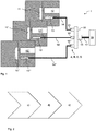
- Fig. 1 1 shows a production machine 1 of the plastics processing industry with a cabling interface 10 according to the invention and an evaluation unit 20.
- Fig. 2 shows a flow chart with steps c), d), e) of a method for converting a production machine of the plastics processing industry.
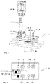
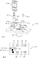
- the Fig. 3 to 14 show several embodiments of the cabling interface 10.
- the cabling interface 10 is designed for two different connection standards A, B, according to embodiments of FIGS Fig. 7 to 14
- the cabling interface 10 is designed for three different connection standards A, B, C, D.
- the production machine 1 of the plastics processing industry Fig. 1 comprises a tool having a multi-cavity injection mold with a plurality of cavities 11, 11 ', 11 "and an injection channel 12.
- a piezoelectric pressure sensor 13, 13', 13" is arranged on each cavity 11, 11 ', 11 " 13, 13 ', 13 “are crystallographically oriented so that on it produces pressure producing electric polarization charges.
- the electric polarization charges are proportional to the size of the internal cavity pressure acting in the cavity 11, 11 ', 11 "and are tapped off via electrodes 16.
- the piezoelectric pressure sensors 13, 13', 13" detect a profile of the cavity pressure in the cavities 11, 11 ', 11
- Each piezoelectric pressure transducer 13, 13 ', 13 "derives an electrical charge signal via an inner cable 14, 14', 14" to the cabling interface 10 for a detected cavity pressure of a cavity 11, 11 ', 11 ".
- the piezoelectric pressure sensors 13, 13 ', 13 are integral with the inner cables 14, 14', 14".
- the multi-cavity injection mold can be more than those in Fig. 1 have shown three cavities, it may for example have 50 cavities.
- more than three inner cables 14, 14 ', 14 can derive electrical charge signals to the cabling interface 10 in the Fig. 3 to 14
- four to eight inner cables 14 - 14 '''''' can derive electrical charge signals to the cabling interface 10.
- the inner cables 14, 14 ', 14 are electrically connected to the cabling interface 10 via inner sleeves 15, 15', 15".
- the inner cables 14, 14 ', 14 “have an electrical conductor for deriving the electrical charge signals, and the inner cables 14, 14', 14" can shield the electrical charge signals from electromagnetic and electrical interference. Such a shield can also be done by a not shown in the figures housing the tool.
- the inner bushings 15, 15 ', 15 are on a tool inside the wiring interface 10 arranged.
- a first connection standard A refers to a detachable electrical connection of a coaxial cable to a coaxial socket of the cabling interface 10.
- the coaxial cable and the coaxial socket shield the electrical charge signal electromagnetically.
- the coaxial cable is inserted into the coaxial socket and locked. The snapping gives an acoustic confirmation.
- the electrical connection between coaxial cable and coaxial socket is reversibly solvable. In the Fig.
- the coaxial cable is shown as an inner cable 14 ', 14''', 14 ''''' and the coaxial socket is shown as an inner sleeve 15 ', 15''', 15 ''''.
- Such a coaxial cable is commercially available under a type designation 1943C of the Kistler Group, details are described in data sheet 1631C-000-346d-12.13.
- a second connection standard B refers to a detachable electrical connection of a Pierce contact cable connector to a socket of the cabling interface 10.
- the electrical charge signal is electromagnetically unshielded in a single wire cable.
- the single-wire cable has a jacket with electrical insulation. In order to be able to easily lay the single-wire cable in the tool, it is cut to length on site and inserted into the Pierce contact cable connector with a non-stripped cable end.
- the Pierce contact cable connector has a housing and pierce contacts on. By pressing the Pierce contacts the electrical insulation of the inserted cable end is pierced and the cable end mechanically and electrically connected to the housing. The pressing of the Pierce contacts, respectively a mechanical engagement of these Pierce contacts, gives an acoustic confirmation.
- Pierce-contact cable plug and socket The electrical connection between Pierce-contact cable plug and socket is reversible solvable.
- the single-wire cable with pierce-contact cable connector is shown as an inner cable 14 ', 14''''', 14 ''''' and the socket is as inner socket 15 ', 15''''', 15 ''''' shown.
- Such a Pierce contact cable connector is commercially available under a PTPM 0.4 /..P product family from Phoenix Contact.
- a third connection standard C refers to an electrical connection of a single-wire cable with a insulation displacement contact socket of the cabling interface 10.
- the electrical charge signal is electromagnetically unshielded in the single-wire cable.
- the single-wire cable has a jacket with electrical insulation.
- An electrical connection is made by stripping the inserted cable end with a specially shaped cutting metal and clamping it with the insulation displacement contact bushing. The assembly aid is removed.
- the electrical connection is reversibly solvable only a couple of times. In the Fig. 7, 8 .
- the single-wire cable is shown as an inner cable 14 ', 14'''',14'''' and the socket is shown as an inner sleeve 15 ', 15'''',15''''.
- Such a single-wire cable is under the type designations 1666A ..., 1674AZsp and 1900A17 ... commercially available from the Kistler Group.
- Such a socket is commercially available under the type designations 1712A0 and 1714A0 of the Kistler Group, details are described in data sheet 960-112d-02.15.
- a fourth connection standard D refers to a detachable electrical connection of an insulation displacement contact cable connector to a socket of the cabling interface 10.
- the electrical charge signal is not electromagnetically shielded in a single-wire cable.
- the single-wire cable has a jacket with electrical insulation. In order to be able to easily lay the single-wire cable in the tool, it is cut to length on site and inserted into the insulation displacement contact with a non-stripped cable end.
- the insulation displacement contact cable connector has a housing with a cutting clamp. By pressing the cutting terminal, the electrical insulation of the inserted cable end is cut and stripped, the cable wire is slightly cut and mechanically and electrically connected to the housing. Actuation of the insulation displacement terminal gives an acoustic confirmation.
- insulation displacement contact cable connector with the socket is reversibly solvable.
- Fig. 9 to 12 is the single-wire cable with insulation displacement contact cable connector shown as inner cable 14 "and the socket is shown as an inner sleeve 15".
- Such an insulation displacement contact cable connector is commercially available under a CIOC-M article family from Phoenix Contact.
- the cabling interface 10 is designed for a plurality of electrical connections I-VIII with a plurality of inner cables 14-14 ''''''.
- the inner cables 14 - 14 '''''' form the electrical connections I - VIII via the inner bushes 15 - 15 '''''''' with the wiring interface 10.
- At least two inner bushings 15-15 ''''''''''''' have different connection standards A, B, C, D for an electrical connection I-VIII. In the embodiments according to Fig. 3, 4 .
- the cabling interface 10 is designed for up to four electrical connections I-IV, wherein each electrical connection I-IV can be implemented in two different connection standards A, B.
- each electrical connection I-IV in three different connection standards A, B, D are implemented.
- each electrical connection I-VIII can be implemented in two different connection standards A, B, C, D.
- Fig. 4 . 6 . 8th . 10 in the embodiments according to FIGS. 9 and 10 .
- the cabling interface 10 has a larger number of inner bushes 15-15 ''''''', as it is designed for electrical connections I - VIII.
- inner bushes 15-15 ''''''' In the embodiments according to Fig. 3, 4 . 7 and 8 it has eight inner bushes 15 - 15 '''on.
- FIGS. 9 and 10 it has twelve inner bushes 15-15 '''.
- 6 . 11 to 14 it has sixteen inner bushes 15-15 '''''''''''on.
- the cabling interface 10 has a plurality of indicators 18 - 18 ''''''' on.
- the indicators 18-18 '''''''' are arranged on the tool inner side of the cabling interface 10.
- Each indicator 18-18 '''''''' has a designation.
- Each inner bushing 15-15 '''''''' is assigned an indicator 18-18 '''''''' and the electrical connection I-VIII of an inner bush 15-15 ''''''''''is identified by the name of its associated indicator 18 - 18'''''''''.
- the electrical connection I-VIII and the connection standard A, B, C, D of the inner bushings 15-15 ''''''' are clearly indicated by the indicators 18-18 '''''''''.
- the name can be a label, a light, etc. In the FIGS. 4 . 6 . 8th . 10 . 12 and 14 the label is a label like "A II" in Fig. 4 or "C VI" in Fig.
- the term also be a lamp such as a light-emitting diode (LED), which lights LED in two different colors, in a first color, when an inner cable is mechanically and electrically connected to the inner socket to which the indicator of the LED is associated and in a second color if no inner cable is mechanically and electrically connected to the inner bush, to which the indicator of the LED is assigned.
- the color control of the LED can be done by a sensor that detects a pressure at an electrical connection between the inner cable and inner socket or it can be done by a switch that switches with an electrical connection between the inner cable and inner socket.
- connection II two inner sockets 15 'with different connection standards A, B available.
- An inner cable 14 ' is electrically connected to the one inner sleeve 15' via the second connection standard B.
- the inner cable 14 ' is clearly visible with the inner sleeve 15' mechanically and electrically connected.
- this is represented by a black filled inner sleeve 15 'of the compound standard B.
- This electrical connection II via the connection standard B is clearly recognizable by a designation with the label "B II" of the indicator 18.
- the indicator 18 of the inner sleeve 15 'with which the inner cable 14' is electrically connected thus indicates that for this connection standard B, an electrical connection I has taken place and how this electrical connection I is identified.
- the indicator 18 of at least one other inner sleeve 15 ', which is not electrically connected to the inner cable 14' is connected is indicated by the label with the label "A II" that for this connection standard A no electrical connection I has occurred.
- the visibility of the inner cable 14 'in the inner sleeve 15' of the electrical connection I avoids the risk that another inner cable 14 - 14 ''''' with the other inner sockets 15 of the electrical connection I via the first connection standard A is electrically connected.
- a piezoelectric pressure transducer 13, 13 ', 13 "to be replaced can be replaced by an available piezoelectric pressure transducer 13, 13', 13" whose inner cable 14 - 14 "'''''has a different connection standard A, B, C, D than that of the inner cable 14-14''''''of the piezoelectric pressure transducer 13, 13', 13 "to be replaced, in a step a) existing piezoelectric pressure transducer 13, 13 ', 13 "removed from the production machine 1 and in a step b) a new piezoelectric pressure transducer 13, 13', 13" installed in the production machine 1, which the existing piezoelectric pressure transducer 13, 13 ', 13th and whose inner cable 14-14 '''''' has one of the different connection standards A, B, C, D of the cabling interface 10.
- step b) the electrical connection I - VIII of the inner cable 14 - 14 '''''' of the new piezoelectric pressure transducer 13, 13 ', 13 "with one of at least two inner bushes 15 - 15''''''Which inner bushes 15 - 15'''''' for the electrical connection I - VIII different connection standards A, B, C, D.
- the electrical connection I - VIII of the inner cable 14 - 14 ''''''' takes place with that of the inner bushes 15 - 15 '''''', which inner bush 15 - 15 ''''''' the same connection standard A , B, C, D as the inner cable 14 - 14 '''''' has.
- the cabling interface 10 has an outer socket 16.
- the outer socket 16 is arranged on a tool outer side of the wiring interface 10.
- the outer socket 16 has electrical conductors for deriving the electrical charge signals.
- a number of electrical conductors of the outer socket 16 corresponds at least to the number of electrical connections I-VIII of the wiring interface 10.
- the outer socket 16 has at least four to eight electrical conductors.
- An electrically shielded outer cable 17 is reversibly releasably connected to the outer sleeve 16 electrically connected.
- the outer cable 17 derives the electrical charge signals to the evaluation unit 20.
- Such an outer bushing 16 is commercially available under the type designation 1710B ... of the Kistler Group.
- Such an outer cable 17 is commercially available under the type designations 1995A ..., 1997A ..., 1999A ... of the Kistler Group.
- Such an evaluation unit 20 is commercially available under a name CoMo Injection System with a type designation 2869B ... of the Kistler Group, details are described in a data sheet 2869B_000-549.
- the cabling interface 10 has electrical conductors which electrically connect the electrical conductors of the inner sleeves 15-15 '''''' to the electrical conductors of the External socket 16 connects. Electrical conductors of the inner bushings 15-15 ''''''', which have different connection standards A, B, C, D for an electrical connection I-VIII, are connected in parallel. These parallel electrical conductors of the inner bushes 15 - 15 '''''''are electrically connected to an electrical conductor for this electrical connection I - VIII of the outer sleeve 16. For example, in the embodiment according to 3 and 4 for an electrical connection II two inner sockets 15 'with different connection standards A, B available. The electrical conductors of these inner sockets 15 'are connected in parallel on the wiring interface 10 and electrically connected to an electrical conductor of the outer socket 16 for the electrical connection II.
- Fig. 2 1 shows a flowchart with steps c), d), e) of a method for converting the production machine 1.
- the production machine 1 has an existing cabling interface 0.
- a new inventive cabling interface 10 is provided, which is electrically connectable to the inner cables 14-14 ''''' via at least two different connection standards A, B, C, D.
- the existing cabling interface 0 is removed from the production machine 1.
- the new cabling interface 10 is installed in the production machine 1.
- the built-in new cabling interface 10 is electrically connected to the inner cables 14-14 ''''''.
- step e) an electrical connection I-VIII of an inner cable 14-14 '''''' takes place with one of at least two inner sockets 15-15 ''''' of the built-in cabling interface 10, which inner bushes 15 - 15 ''''''for the electrical connection I - VIII have different connection standards A, B, C, D.
- step e) is indicated by the indicator 18 - 18 '''''' of the inner sleeve 15 - 15 '''''' with which the inner cable 14 - 14 '''''''is electrically connected, in that an electrical connection I - VIII has taken place for this connection standard A, B, C, D and how this electrical connection I - VIII is identified.
- the indicator 18 - 18 ''''''' of the at least one other inner sleeve 15 - 15 '''''', which is not electrically connected to the inner cable 14 - 14 ''''', is indicated that no electrical connection I - VIII has been made for this connection standard A, B, C, D.
- the inner cables 14-14 '"''''of the piezoelectric pressure sensors 13, 13', 13" can be electrically connected to a new evaluation unit 20 via the cabling interface 10.
Landscapes
- Engineering & Computer Science (AREA)
- Manufacturing & Machinery (AREA)
- Mechanical Engineering (AREA)
- Physics & Mathematics (AREA)
- Microelectronics & Electronic Packaging (AREA)
- Optics & Photonics (AREA)
- Details Of Connecting Devices For Male And Female Coupling (AREA)
- Measuring Fluid Pressure (AREA)
- Processing Of Terminals (AREA)
- Manufacturing Of Electrical Connectors (AREA)
Description
- Die Erfindung betrifft eine Anordnung umfassend eine Produktionsmaschine der kunststoffverarbeitenden Industrie, ein Innenkabel und eine Verkabelungsschnittstelle, sowie Verfahren zum Unterhalt und zum Umrüsten einer solchen Anordnung.
- Die Schrift
CH692891A5 - Nun hat das Werkzeug mit der Mehrkavitäten-Spritzgiessform einen komplexen Aufbau und eine Länge der Kabel im Werkzeug ist daher kabelspezifisch. Um die Kabel im Werkzeug einfach verlegen zu können, werden elektromagnetisch nicht abgeschirmte Kabel verwendet, deren Länge sich vor Ort einfach konfektionieren lässt. Eine gesonderte Abschirmung der elektrischen Ladungssignale vor elektromagnetischen und elektrischen Störeinflüssen ist auch nicht nötig, denn sie erfolgt durch ein Gehäuse des Werkzeuges. Die nicht abgeschirmten Kabel sind somit Innenkabel. Daher weist das Werkzeug die Verkabelungsschnittstelle auf, um die Innenkabel auf einer Werkzeuginnenseite Innenkabel einzeln aufzunehmen und die elektrischen Ladungssignale jedes aufgenommenen Innenkabels zu einem elektromagnetisch abgeschirmten Aussenkabel auf einer Werkzeugaussenseite zu überführen. Das Aussenkabel leitet die elektrischen Ladungssignale zum elektrischen Verstärker ab.
- Es ist allgemeiner Wunsch, eine solche Verkabelungsschnittstelle für eine Produktionsmaschine der kunststoffverarbeitenden Industrie flexibel an technische Bedürfnisse von Forschung und Industrie anzupassen.
- So zeigt die Schrift
WO2007/016799A1 eine weitere bekannte Verkabelungsschnittstelle für eine Produktionsmaschine der kunststoffverarbeitenden Industrie. In der Produktionsmaschine werden mehrere typverschiedene Messsignale über mehrere Innenkabel abgeleitet. Die Verkabelungsschnittstelle weist einen Signalumformer und eine Ausgabeschnittstelle auf. Der Signalumformer wandelt die typverschiedenen Messsignale in typgleiche Messsignale. Die typverschiedenen Messsignale sind elektrischen Ladungssignale von piezoelektrischen Druckaufnehmern und elektrische Thermospannungen von Thermoelementen. Die Ausgabeschnittstelle leitet die typgleichen Messsignale über ein einziges Aussenkabel an eine ausserhalb der Produktionsmaschine angeordnete Auswerteeinheit ab. Das Aussenkabel ist elektromagnetisch abgeschirmt. Das Aussenkabel ist elektrisch und mechanisch lösbar mit der Ausgabeschnittstelle verbunden. - Eine solche bekannte Verkabelungsschnittstelle für eine Produktionsmaschine der kunststoffverarbeitenden Industrie ist unter einer Typenbezeichnung 1710B... der Kistler Gruppe kommerziell erhältlich, Details sind in einem Datenblatt 960-112d-02.15 beschrieben. Mindestens ein piezoelektrischer Druckaufnehmer pro Kavität leitet über ein Innenkabel elektrische Ladungssignale an die Verkabelungsschnittstelle ab. Bis zu acht Innenkabel lassen sich mit einer Werkzeuginnenseite der Verkabelungsschnittstelle elektrisch verbinden. Von der Werkzeuginnenseite werden die elektrischen Ladungssignale auf eine Werkzeugaussenseite überführt. Ein an der Werkzeugaussenseite elektrisch und mechanisch lösbar mit der Verkabelungsschnittstelle verbundenes Aussenkabel leitet die elektrischen Ladungssignale zu einer Auswerteeinheit ab. Das Aussenkabel ist elektromagnetisch abgeschirmt.
- Eine sehr ähnliche bekannte Verkabelungsschnittstelle für eine Produktionsmaschine der kunststoffverarbeitenden Industrie ist unter den Typenbezeichnungen PZ-4 und PZ-8 der RJG Inc. kommerziell erhältlich. Die äusseren Abmessungen für einen Einbau in eine Produktionsmaschine der Typen 1710B... der Kistler Gruppe und der Typen PZ-4 und PZ-8 der RJG Inc. sind weitgehend identisch.
-
US20090269977A1 bezieht sich auf eine elektrische Verbinderanordnung mit einer Haltevorrichtung, die eine Vielzahl von Kabelpositionshohlräume aufweist. Jeder Kabelpositionshohlraum hat einen frontseitigen Zugang und einen rückseitigen Ausgang. Mehrere Kabelenden sind durch die Ausgänge in die Kabelpositionshohlräume geführt. Drähte der Kabelenden sind mit verschiedenen Computeranschlüssen im Inneren der Haltevorrichtung verlötet. Die Computeranschlüsse sind durch die frontseitigen Zugänge der Haltevorrichtung für Computerkabel zugänglich. -
GB2439980A1 - Aufgabe der vorliegenden Erfindung ist es, eine bekannte Verkabelungsschnittstelle für eine Produktionsmaschine der kunststoffverarbeitenden Industrie flexibel an technische Bedürfnisse von Forschung und Industrie anzupassen.
- Diese Aufgabe wird durch die Merkmale der unabhängigen Ansprüchen 1, 5 und 8 gelöst.
- Die Erfindung betrifft eine Anordnung gemäß Anspruch 1, umfassend eine Produktionsmaschine der kunststoffverarbeitenden Industrie, ein Innenkabel und eine Verkabelungsschnittstelle.
- Somit lassen sich über die Verkabelungsschnittstelle elektrische Ladungssignale an eine Auswerteeinheit ableiten, auch wenn die Innenkabel der piezoelektrischen Druckaufnehmer, welche die elektrischen Ladungssignale liefern, unterschiedliche Verbindungsstandards aufweisen. Dies erlaubt einen flexiblen Unterhalt der Produktionsmaschine. Bei Ersatz eines eingebauten piezoelektrischen Druckaufnehmers, kann dieser durch einen gerade verfügbaren piezoelektrischen Druckaufnehmer ersetzt werden, auch wenn dieser einen anderen Verbindungsstandard aufweist, was Aufwand und Zeit spart. Auch besteht kein Zwang mehr, piezoelektrische Druckaufnehmer mit bestimmten Verbindungsstandards einzusetzen. Somit lassen die piezoelektrischen Druckaufnehmer mit dem besten Preis/Leistungsverhältnis einsetzen.
- Die Erfindung betrifft auch ein Verfahren zum Unterhalt einer Produktionsmaschine der kunststoffverarbeitenden Industrie mit einer Anordnung nach einem der Ansprüche 1 bis 4, und ein Verfahren zum Umrüsten einer Produktionsmaschine der kunststoffverarbeitenden Industrie mit einer Anordnung nach einem der Ansprüche 1 bis 4.
- Somit wird eine bestehende Verkabelungsschnittstelle durch eine Verkabelungsschnittstelle mit mehreren unterschiedlichen Verbindungsstandards ersetzt. Dies erlaubt ein flexibles Nachrüsten der Produktionsmaschine. Eingebaute piezoelektrische Druckaufnehmer, deren Innenkabel einen bestimmten Verbindungsstandard aufweisen, lassen sich über die Verkabelungsschnittstelle mit einer neuen Auswerteeinheit elektrisch verbinden. Somit lässt sich eine Produktionsmaschine zu einem besten Preis/Leistungsverhältnis mit einer neuen Auswerteeinheit nachrüsten.
- Im Folgenden wird die Erfindung beispielhaft unter Beizug der Figuren näher erklärt. Es zeigen
- Fig. 1
- eine schematische Darstellung einer Produktionsmaschine der kunststoffverarbeitenden Industrie mit einer erfindungsgemässen Verkabelungsschnittstelle;
- Fig. 2
- ein Flussdiagramm der Schritte eines Verfahrens zum Umrüsten einer Produktionsmaschine der kunststoffverarbeitenden Industrie;
- Fig. 3
- eine perspektivische Ansicht einer ersten Ausführungsform einer erfindungsgemässen Verkabelungsschnittstelle mit zwei unterschiedlichen Verbindungsstandards;
- Fig. 4
- eine Draufsicht der ersten Ausführungsform einer Verkabelungsschnittstelle nach
Fig. 3 ; - Fig. 5
- eine perspektivische Ansicht einer zweiten Ausführungsform einer erfindungsgemässen Verkabelungsschnittstelle mit zwei unterschiedlichen Verbindungsstandards;
- Fig. 6
- eine Draufsicht der zweiten Ausführungsform einer Verkabelungsschnittstelle nach
Fig. 5 ; - Fig. 7
- eine perspektivische Ansicht einer dritten Ausführungsform einer erfindungsgemässen Verkabelungsschnittstelle mit drei unterschiedlichen Verbindungsstandards;
- Fig. 8
- eine Draufsicht der dritten Ausführungsform einer Verkabelungsschnittstelle nach
Fig. 7 ; - Fig. 9
- eine perspektivische Ansicht einer vierten Ausführungsform einer erfindungsgemässen Verkabelungsschnittstelle mit drei unterschiedlichen Verbindungsstandards;
- Fig. 10
- eine Draufsicht der vierten Ausführungsform einer Verkabelungsschnittstelle nach
Fig. 9 ; - Fig. 11
- eine perspektivische Ansicht einer fünften Ausführungsform einer erfindungsgemässen Verkabelungsschnittstelle mit drei unterschiedlichen Verbindungsstandards;
- Fig. 12
- eine Draufsicht der fünften Ausführungsform einer Verkabelungsschnittstelle nach
Fig. 11 ; - Fig. 13
- eine perspektivische Ansicht einer sechsten Ausführungsform einer erfindungsgemässen Verkabelungsschnittstelle mit drei unterschiedlichen Verbindungsstandards;
- Fig. 14
- eine Draufsicht der sechsten Ausführungsform einer Verkabelungsschnittstelle nach
Fig. 13 . -
Fig. 1 zeigt eine Produktionsmaschine 1 der kunststoffverarbeitenden Industrie mit einer erfindungsgemässen Verkabelungsschnittstelle 10 und einer Auswerteeinheit 20.Fig. 2 zeigt ein Flussdiagramm mit Schritten c), d), e) eines Verfahrens zum Umrüsten einer Produktionsmaschine der kunststoffverarbeitenden Industrie. DieFig. 3 bis 14 zeigen mehrere Ausführungsformen der Verkabelungsschnittstelle 10. In den Ausführungsformen nach denFig. 3 bis 6 ist die Verkabelungsschnittstelle 10 für zwei unterschiedliche Verbindungsstandards A, B ausgelegt, in den aus Ausführungsformen nach denFig. 7 bis 14 ist die Verkabelungsschnittstelle 10 für drei unterschiedliche Verbindungsstandards A, B, C, D ausgelegt. - Die Produktionsmaschine 1 der kunststoffverarbeitenden Industrie nach
Fig. 1 weist ein Werkzeug mit einer Mehrkavitäten-Spritzgiessform mit mehrere Kavitäten 11, 11', 11" und einem Einspritzkanal 12 auf. An jeder Kavität 11, 11', 11" ist ein piezoelektrischer Druckaufnehmer 13, 13', 13" angeordnet. Die piezoelektrischen Druckaufnehmer 13, 13', 13" sind kristallographisch so orientiert, dass ein auf sie wirkender Druck elektrische Polarisationsladungen erzeugt. Die elektrischen Polarisationsladungen sind proportional zur Grösse des in der Kavität 11, 11', 11" wirkenden Werkzeuginnendruckes und werden über Elektroden abgegriffen. Die piezoelektrischen Druckaufnehmer 13, 13', 13" erfassen einen Verlauf des Werkzeuginnendruckes in den Kavitäten 11, 11', 11" dynamisch. Jeder piezoelektrische Druckaufnehmer 13, 13', 13" leitet für einen erfassten Werkzeuginnendruck einer Kavität 11, 11', 11" ein elektrisches Ladungssignal über ein Innenkabel 14, 14', 14" an die Verkabelungsschnittstelle 10 ab. Die piezoelektrischen Druckaufnehmer 13, 13', 13" sind einstückig mit den Innenkabeln 14, 14', 14". Bei Kenntnis der vorliegenden Erfindung kann die Mehrkavitäten-Spritzgiessform mehr als die inFig. 1 dargestellten drei Kavitäten aufweisen, so kann sie beispielsweise 50 Kavitäten aufweisen. Auch können mehr als drei Innenkabel 14, 14', 14" elektrische Ladungssignale an die Verkabelungsschnittstelle 10 ableiten, in denFig. 3 bis 14 können vier bis acht Innenkabel 14 - 14''''''' elektrische Ladungssignale an die Verkabelungsschnittstelle 10 ableiten. - Nach
Fig. 1 sind die Innenkabel 14, 14', 14" über Innenbuchsen 15, 15', 15" mit der Verkabelungsschnittstelle 10 elektrisch verbunden. Die Innenkabel 14, 14', 14" weisen einen elektrischen Leiter für das Ableiten der elektrischen Ladungssignale auf. Die Innenkabel 14, 14', 14" können eine Abschirmung der elektrischen Ladungssignale vor elektromagnetischen und elektrischen Störeinflüssen aufweisen. Eine solche Abschirmung kann auch durch ein in den Figuren nicht eingezeichnetes Gehäuse des Werkzeuges erfolgen. Die Innenbuchsen 15, 15', 15" sind auf einer Werkzeuginnenseite der Verkabelungsschnittstelle 10 angeordnet. Die Innenkabel 14, 14', 14" und die Innenbuchsen 15, 15', 15" sind aufeinander abgestimmt und weisen unterschiedliche Verbindungsstandards A, B, C, D auf:
Ein erster Verbindungsstandard A bezieht sich auf eine lösbare elektrische Verbindung eines Koaxialkabels mit einer Koaxialbuchse der Verkabelungsschnittstelle 10. Das Koaxialkabel und die Koaxialbuchse schirmen das elektrische Ladungssignal elektromagnetisch ab. Zum Herstellen einer elektrischen Verbindung wird das Koaxialkabel in die Koaxialbuchse gesteckt und eingerastet. Das Einrasten gibt eine akustische Bestätigung. Die elektrische Verbindung zwischen Koaxialkabel und Koaxialbuchse ist reversibel lösbar. In denFig. 3 bis 14 ist das Koaxialkabel als Innenkabel 14', 14''', 14''''''' dargestellt und die Koaxialbuchse ist als Innenbuchse 15', 15''', 15'''' dargestellt. Solch ein Koaxialkabel ist unter einer Typenbezeichnung 1943C der Kistler Gruppe kommerziell erhältlich, Details sind im Datenblatt 1631C-000-346d-12.13 beschrieben. - Ein zweiter Verbindungsstandard B bezieht sich auf eine lösbare elektrische Verbindung eines Pierce-Kontakt Kabelsteckers mit einer Buchse der Verkabelungsschnittstelle 10. Das elektrische Ladungssignal ist in einem eindrahtigen Kabel mit elektromagnetisch nicht abgeschirmt. Das eindrahtige Kabel weist einen Mantel mit elektrischer Isolierung auf. Um das eindrahtige Kabel im Werkzeug einfach verlegen zu können, wird es vor Ort abgelängt und mit einem nicht abisolierten Kabelende in den Pierce-Kontakt Kabelstecker eingeführt. Der Pierce-Kontakt Kabelstecker weist ein Gehäuse und Pierce-Kontakten auf. Durch Betätigen der Pierce-Kontakte wird die elektrische Isolierung des eingeführten Kabelendes durchstochen und das Kabelende mechanisch und elektrisch mit dem Gehäuse verbunden. Das Betätigen der Pierce-Kontakte, respektive ein mechanisches Einrasten dieser Pierce-Kontakte, gibt eine akustische Bestätigung. Die elektrische Verbindung zwischen Pierce-Kontakt Kabelstecker und Buchse ist reversibel lösbar. In den
Fig. 3 bis 14 ist das eindrahtige Kabel mit Pierce-Kontakt Kabelstecker als Innenkabel 14', 14''''', 14'''''' dargestellt und die Buchse ist als Innenbuchse 15', 15''''', 15'''''' dargestellt. Solch ein Pierce-Kontakt Kabelstecker ist unter einer Artikelfamilie PTPM 0,4/..-P von Phoenix Contact kommerziell erhältlich. - Ein dritter Verbindungsstandard C bezieht sich auf eine elektrische Verbindung eines eindrahtigen Kabels mit einer Schneidklemm-Kontakt Buchse der Verkabelungsschnittstelle 10. Das elektrische Ladungssignal ist im eindrahtigen Kabel elektromagnetisch nicht abgeschirmt. Das eindrahtige Kabel weist einen Mantel mit elektrischer Isolierung auf. Für ein einfaches Verlegen im Werkzeug, wird das eindrahtige Kabel vor Ort abgelängt und mit einem nicht abisolierten Kabelende in die Schneidklemm-Kontakt Buchse eingeführt. Eine elektrische Verbindung wird hergestellt, in dem das eingeführte Kabelende mit einem speziell geformten Schneidmetall abisoliert und mit der Schneidklemm-Kontakt Buchse geklemmt wird. Die Montagehilfe wird entfernt. Die elektrische Verbindung ist nur ein paarmal reversibel lösbar. In den
Fig. 7, 8 ,13 und 14 ist das eindrahtige Kabel als Innenkabel 14', 14'''', 14''''' dargestellt und die Buchse ist als Innenbuchse 15', 15'''', 15''''' dargestellt. Solch ein eindrahtiges Kabel ist unter den Typenbezeichnungen 1666A..., 1674AZsp und 1900A17... von der Kistler Gruppe kommerziell erhältlich. Solch eine Buchse ist unter den Typenbezeichnungen 1712A0 und 1714A0 der Kistler Gruppe kommerziell erhältlich, Details sind im Datenblatt 960-112d-02.15 beschrieben. - Ein vierter Verbindungsstandard D bezieht sich auf eine lösbare elektrische Verbindung eines Schneidklemm-Kontakt Kabelsteckers mit einer Buchse der Verkabelungsschnittstelle 10. Das elektrische Ladungssignal ist in einem eindrahtigen Kabel elektromagnetisch nicht abgeschirmt. Das eindrahtige Kabel weist einen Mantel mit elektrischer Isolierung auf. Um das eindrahtige Kabel im Werkzeug einfach verlegen zu können, wird es vor Ort abgelängt und mit einem nicht abisolierten Kabelende in den Schneidklemm-Kontakt Kabelstecker eingeführt. Der Schneidklemm-Kontakt Kabelstecker weist ein Gehäuse mit einer Schneidklemme auf. Durch Betätigen der Schneidklemme wird die elektrische Isolierung des eingeführten Kabelendes durchschnitten und abisoliert, auch der Kabeldraht wird leicht angeschnitten und mechanisch und elektrisch mit dem Gehäuse verbunden. Das Betätigen der Schneidklemme gibt eine akustische Bestätigung. Die elektrische Verbindung zwischen Schneidklemm-Kontakt Kabelstecker mit der Buchse ist reversibel lösbar. In den
Fig. 9 bis 12 ist das eindrahtige Kabel mit Schneidklemm-Kontakt Kabelstecker als Innenkabel 14" dargestellt und die Buchse ist als Innenbuchse 15" dargestellt. Solch ein Schneidklemm-Kontakt Kabelstecker ist unter einer Artikelfamilie CIOC-M von Phoenix Contact kommerziell erhältlich. - Bei Kenntnis der vorliegenden Erfindung kann der Fachmann weitere, hier nicht im Detail beschriebene Verbindungsstandards verwenden.
- Die Verkabelungsschnittstelle 10 ist für mehrere elektrische Verbindungen I - VIII mit mehreren Innenkabeln 14 - 14''''''' ausgelegt. Die Innenkabel 14 - 14''''''' bilden die elektrischen Verbindungen I - VIII über die Innenbuchsen 15 - 15''''''''' mit der Verkabelungsschnittstelle 10. Die Innenbuchsen 15 - 15''''''''' weisen elektrische Leiter für das Ableiten der elektrischen Ladungssignale auf. Mindestens zwei Innenbuchsen 15 - 15'''''''''' weisen für eine elektrische Verbindung I - VIII unterschiedliche Verbindungsstandards A, B, C, D auf. In den Ausführungsformen nach
Fig. 3, 4 ,7 und 8 ist die Verkabelungsschnittstelle 10 für bis zu vier elektrische Verbindungen I - IV ausgelegt, wobei jede elektrische Verbindung I - IV in zwei unterschiedlichen Verbindungsstandards A, B umsetzbar ist. In den Ausführungsformen nachFig. 9 und 10 ist sie für bis zu vier elektrische Verbindungen I - IV ausgelegt, wobei jede elektrische Verbindung I - IV in drei unterschiedlichen Verbindungsstandards A, B, D umsetzbar sind. In den Ausführungsformen nachFig. 5, 6 ,11 bis 14 ist sie für bis zu acht elektrische Verbindungen I - VIII ausgelegt, wobei jede elektrische Verbindung I - VIII in zwei unterschiedlichen Verbindungsstandards A, B, C, D umsetzbar sind. In denFig. 4 ,6 ,8 ,10 ,12 und14 sind die Innenbuchsen 15 - 15''''''', die elektrisch mit einem Innenkabel 14 - 14''''''' verbunden sind, schwarz ausgefüllt dargestellt. Bei Kenntnis der vorliegenden Erfindung kann der Fachmann für eine elektrische Verbindung auch mehr als drei Innenbuchsen mit unterschiedlichen Verbindungsstandards vorsehen. - Somit weist die Verkabelungsschnittstelle 10 eine grössere Anzahl Innenbuchsen 15 - 15''''''''' auf, als sie für elektrische Verbindungen I - VIII ausgelegt ist. In den Ausführungsformen nach
Fig. 3, 4 ,7 und 8 weist sie acht Innenbuchsen 15 - 15''' auf. In den Ausführungsformen nachFig. 9 und 10 weist sie zwölf Innenbuchsen 15 - 15'''. In den Ausführungsformen nachFig. 5, 6 ,11 bis 14 weist sie sechzehn Innenbuchsen 15 - 15''''''''' auf. - Die Verkabelungsschnittstelle 10 weist mehrere Indikatoren 18 - 18''''''''' auf. Die Indikatoren 18 - 18''''''''' sind auf der Werkzeuginnenseite der Verkabelungsschnittstelle 10 angeordnet. Jeder Indikator 18 - 18''''''''' weist eine Bezeichnung auf. Jeder Innenbuchse 15 - 15''''''''' ist ein Indikator 18 - 18''''''''' zugeordnet und die elektrische Verbindung I - VIII einer Innenbuchse 15 - 15''''''''' ist durch die Bezeichnung des ihr zugeordneten Indikators 18 - 18''''''''' identifiziert. Auch ist der Verbindungsstandard A, B, C, D einer Innenbuchse 15 - 15''''''''' durch die Bezeichnung des der Innenbuchse 15 - 15''''''''' zugeordneten Indikators 18 - 18''''''''' identifiziert. Somit werden über die Indikatoren 18 - 18''''''''' die elektrische Verbindung I - VIII und der Verbindungsstandard A, B, C, D der Innenbuchsen 15 - 15''''''''' eindeutig aufgezeigt. Die Bezeichnung kann ein Label, eine Leuchte, usw. sein. In die
Figuren 4 ,6 ,8 ,10 ,12 und14 ist die Bezeichnung ein Label wie "A II" inFig. 4 oder "C VI" inFig. 14 . Bei Kenntnis der vorliegenden Erfindung kann die Bezeichnung auch eine Leuchte wie eine Licht emittierende Diode (LED) sein, welche LED in zwei unterschiedlichen Farben leuchtet, in einer ersten Farbe, wenn ein Innenkabel mit der Innenbuchse, welcher der Indikator der LED zugeordnet ist mechanisch und elektrisch verbunden ist und in einer zweiten Farbe, wenn kein Innenkabel mit der Innenbuchse, welcher der Indikator der LED zugeordnet ist mechanisch und elektrisch verbunden ist. Die Farbansteuerung der LED kann durch einen Sensor erfolgen, der einen Druck bei einer elektrischen Verbindung zwischen Innenkabel und Innenbuchse erfasst oder sie kann durch einen Schalter erfolgen, der bei einer elektrischen Verbindung zwischen Innenkabel und Innenbuchse schaltet. - Beispielsweise sind in der Ausführungsform nach
Fig. 3 und 4 für eine elektrische Verbindung II zwei Innenbuchsen 15' mit unterschiedlichen Verbindungsstandards A, B vorhanden. Ein Innenkabel 14' ist mit der einen Innenbuchse 15' über den zweiten Verbindungsstandard B elektrisch verbunden. Das Innenkabel 14' ist gut sichtbar mit der Innenbuchse 15' mechanisch und elektrisch verbunden. InFig. 4 ist dies durch eine schwarz ausgefüllte Innenbuchse 15' des Verbindungsstandards B dargestellt. Diese elektrische Verbindung II über den Verbindungsstandard B ist durch eine Bezeichnung mit dem Label "B II" des Indikators 18 eindeutig erkennbar. Der Indikator 18 der Innenbuchse 15' mit welchem das Innenkabel 14' elektrisch verbunden ist zeigt also an, dass für diesen Verbindungsstandard B eine elektrische Verbindung I erfolgt ist und wie diese elektrische Verbindung I identifiziert ist. Und durch den Indikator 18 der mindestens einen anderen Innenbuchse 15', welche nicht mit dem Innenkabel 14' elektrisch verbunden ist, wird durch die Bezeichnung mit dem Label "A II" angezeigt, dass für diesen Verbindungsstandard A keine elektrische Verbindung I erfolgt ist. Somit wird durch die Sichtbarkeit des Innenkabels 14' in der Innenbuchse 15' der elektrischen Verbindung I die Gefahr vermieden, dass ein weiteres Innenkabel 14 - 14''''''' mit der anderen Innenbuchsen 15 der elektrischen Verbindung I über den ersten Verbindungsstandard A elektrisch verbunden wird. - Ein Unterhalt der Produktionsmaschine 1 wird durch die erfindungsgemässe Verkabelungsschnittstelle 10 dahingehend erleichtert, dass ein zu ersetzender piezoelektrischer Druckaufnehmer 13, 13', 13" durch einen verfügbaren piezoelektrischer Druckaufnehmer 13, 13', 13" ersetzt werden kann, dessen Innenkabel 14 - 14''''''' einen anderen Verbindungsstandard A, B, C, D als derjenige des Innenkabels 14 - 14''''''' des zu ersetzenden piezoelektrischen Druckaufnehmers 13, 13', 13" aufweist. In einem Schritt a) wird der bestehende piezoelektrischer Druckaufnehmer 13, 13', 13" aus der Produktionsmaschine 1 ausgebaut und in einem Schritt b) wird ein neuer piezoelektrischer Druckaufnehmer 13, 13', 13" in die Produktionsmaschine 1 eingebaut, welcher den bestehenden piezoelektrischen Druckaufnehmer 13, 13', 13" ersetzt und dessen Innenkabel 14 - 14''''''' einen der unterschiedlichen Verbindungsstandards A, B, C, D der Verkabelungsschnittstelle 10 aufweist. Insbesondere erfolgt beim Schritt b) die elektrische Verbindung I - VIII des Innenkabels 14 - 14''''''' des neuen piezoelektrischen Druckaufnehmers 13, 13', 13" mit einer von mindestens zwei Innenbuchsen 15 - 15''''''', welche Innenbuchsen 15 - 15''''''' für die elektrische Verbindung I - VIII unterschiedliche Verbindungsstandards A, B, C, D aufweisen. Die elektrische Verbindung I - VIII des Innenkabels 14 - 14''''''' erfolgt mit derjenigen der Innenbuchsen 15 - 15''''''', welche Innenbuchse 15 - 15''''''' den gleichen Verbindungsstandard A, B, C, D wie das Innenkabel 14 - 14''''''' aufweist.
- Die Verkabelungsschnittstelle 10 weist eine Aussenbuchse 16 auf. Die Aussenbuchse 16 ist auf einer Werkzeugaussenseite der Verkabelungsschnittstelle 10 angeordnet. Die Aussenbuchse 16 weist elektrische Leiter zum Ableiten der elektrischen Ladungssignale auf. Eine Anzahl elektrische Leiter der Aussenbuchse 16 entspricht mindestens der Anzahl der elektrischen Verbindungen I - VIII der Verkabelungsschnittstelle 10. So weist die Aussenbuchse 16 mindestens vier bis acht elektrische Leiter auf.
- Ein elektrisch abgeschirmtes Aussenkabel 17 ist reversibel lösbar mit der Aussenbuchse 16 elektrisch verbindbar. Das Aussenkabel 17 leitet die elektrischen Ladungssignale zur Auswerteeinheit 20 ab. Solch eine Aussenbuchse 16 ist unter der Typenbezeichnung 1710B... der Kistler Gruppe kommerziell erhältlich. Solch ein Aussenkabel 17 ist unter den Typenbezeichnungen 1995A..., 1997A..., 1999A... der Kistler Gruppe kommerziell erhältlich. Solch eine Auswerteeinheit 20 ist unter einem Namen CoMo Injection System mit einer Typenbezeichnung 2869B... der Kistler Gruppe kommerziell erhältlich, Details sind in einem Datenblatt 2869B_000-549 beschrieben.
- Die Verkabelungsschnittstelle 10 weist elektrische Leiter auf, welche die elektrischen Leiter der Innenbuchsen 15 - 15''''''' elektrisch mit den elektrischen Leitern der Aussenbuchse 16 verbindet. Elektrische Leiter von den Innenbuchsen 15 - 15''''''', welche für eine elektrische Verbindung I - VIII unterschiedliche Verbindungsstandards A, B, C, D aufweisen, sind parallel geschaltet. Diese parallel geschalteten elektrischen Leiter der Innenbuchsen 15 - 15''''''' sind mit einem elektrischen Leiter für diese elektrische Verbindung I - VIII der Aussenbuchse 16 elektrisch verbunden. Beispielsweise sind in der Ausführungsform nach
Fig. 3 und 4 für eine elektrische Verbindung II zwei Innenbuchsen 15' mit unterschiedlichen Verbindungsstandards A, B vorhanden. Die elektrischen Leiter dieser Innenbuchsen 15' sind auf der Verkabelungsschnittstelle 10 parallel geschaltet und mit einem elektrischen Leiter der Aussenbuchse 16 für die elektrische Verbindung II elektrisch verbunden. -
Fig. 2 zeigt ein Flussdiagramm mit Schritten c), d), e) eines Verfahrens zum Umrüsten der Produktionsmaschine 1. Die Produktionsmaschine 1 weist an eine bestehende Verkabelungsschnittstelle 0 auf. In einem Schritt c) wird eine neue erfinderische Verkabelungsschnittstelle 10 bereitgestellt, welche mit den Innenkabeln 14 - 14''''''' über mindestens zwei unterschiedliche Verbindungsstandards A, B, C, D elektrisch verbindbar ist. In einem Schritt d) wird die bestehende Verkabelungsschnittstelle 0 aus der Produktionsmaschine 1 ausgebaut. In einem Schritt e) wird die neuen Verkabelungsschnittstelle 10 in die Produktionsmaschine 1 eingebaut. Die eingebaute neue Verkabelungsschnittstelle 10 wird mit den Innenkabeln 14 - 14''''''' elektrisch verbunden. Im Schritt e) erfolgt eine elektrische Verbindung I - VIII eines Innenkabels 14 - 14''''''' mit einer von mindestens zwei Innenbuchsen 15 - 15''''''' der eingebauten Verkabelungsschnittstelle 10, welche Innenbuchsen 15 - 15''''''' für die elektrische Verbindung I - VIII unterschiedliche Verbindungsstandards A, B, C, D aufweisen. Und im Schritt e) wird durch den Indikator 18 - 18''''''' der Innenbuchse 15 - 15''''''' mit welchem das Innenkabel 14 - 14''''''' elektrisch verbunden ist angezeigt, dass für diesen Verbindungsstandard A, B, C, D eine elektrische Verbindung I - VIII erfolgt ist und wie diese elektrische Verbindung I - VIII identifiziert ist. Und durch den Indikator 18 - 18''''''' der mindestens einen anderen Innenbuchse 15 - 15''''''', welche nicht mit dem Innenkabel 14 - 14''''''' elektrisch verbunden ist, wird angezeigt, dass für diesen Verbindungsstandard A, B, C, D keine elektrische Verbindung I - VIII erfolgt ist. Die Innenkabel 14 - 14''''''' der piezoelektrischen Druckaufnehmer 13, 13', 13" lassen sich über die Verkabelungsschnittstelle 10 mit einer neuen Auswerteeinheit 20 elektrisch verbinden. - Bei Kenntnis der vorliegenden Erfindung kann der Fachmann die Verkabelungsschnittstelle auch in Produktionsmaschinen ausserhalb der kunststoffverarbeitenden Industrie einsetzen.
-
- a) - e)
- Verfahrensschritte
- A, B, C, D
- Verbindungsstandard
- I - VIII
- elektrische Verbindung
- 1
- Produktionsmaschine
- 0
- bestehende Verkabelungsschnittstelle
- 10
- Verkabelungsschnittstelle
- 11, 11', 11"
- Kavität
- 12, 12', 12"
- Einspritzkanal
- 13, 13', 13"
- piezoelektrischer Druckaufnehmer
- 14 - 14'''''''
- Innenkabel
- 15 - 15'''''''
- Innenbuchse
- 16
- Aussenbuchse
- 17
- Aussenkabel
- 18 - 18'''''''
- Indikator
- 20
- Auswerteeinheit
Claims (12)
- Anordnung, umfassend eine Produktionsmaschine (1) der kunststoffverarbeitenden Industrie, ein Innenkabel (14 - 14''''''') und eine Verkabelungsschnittstelle (10); welche Produktionsmaschine (1) mehrere Kavitäten (11, 11', 11") und mehrere piezoelektrische Druckaufnehmer (13, 13', 13") aufweist; wobei an jeder Kavität (11, 11', 11") mindestens ein piezoelektrischer Druckaufnehmer (13, 13', 13") angeordnet ist, welcher piezoelektrische Druckaufnehmer (13, 13', 13") einen Werkzeuginnendruck in der Kavität (11, 11', 11") erfasst und für jeden erfassten Werkzeuginnendruck ein elektrisches Ladungssignal liefert und über das Innenkabel (14 - 14''''''') an die Verkabelungsschnittstelle (10) ableitet; dadurch gekennzeichnet, dass die Innenkabel (14 - 14''''''') über mindestens zwei unterschiedliche Verbindungsstandards (A, B, C, D) mit der Verkabelungsschnittstelle (10) elektrisch verbindbar sind; dass die Verkabelungsschnittstelle (10) mehrere Innenbuchsen (15 - 15''''''') aufweist; und dass die Innenkabel (14 - 14''''''') über die Innenbuchsen (15 - 15''''''') elektrische Verbindungen (I - VIII) mit der Verkabelungsschnittstelle (10) bilden; dass mindestens zwei Innenbuchsen (15 - 15''''''') für eine elektrische Verbindung (I - VIII) unterschiedliche Verbindungsstandards (A, B, C, D) aufweisen; dass die Verkabelungsschnittstelle (10) eine Aussenbuchse (16) aufweist; dass die Aussenbuchse (16) für jede elektrische Verbindung (I - VIII) einen elektrischen Leiter aufweist; dass jede Innenbuchse (15 - 15''''''') für eine elektrische Verbindung (I - VIII) einen elektrischen Leiter aufweist; dass elektrische Leiter von denjenigen Innenbuchsen (15 - 15'''''''), welche für eine elektrische Verbindung (I - VIII) unterschiedliche Verbindungsstandards (A, B, C, D) aufweisen, parallel geschaltet sind; und dass diese parallel geschaltete elektrischen Leiter der Innenbuchsen (15 - 15''''''') mit einem elektrischen Leiter dieser elektrischen Verbindung (I - VIII) der Aussenbuchse (16) elektrisch verbunden sind.
- Anordnung nach Anspruch 1, dadurch gekennzeichnet, dass die Verkabelungsschnittstelle (10) eine grössere Anzahl Innenbuchsen (15 - 15''''''') aufweist, als sie für elektrische Verbindungen (I - VIII) ausgelegt ist.
- Anordnung nach einem der Ansprüche 1 oder 2, dadurch gekennzeichnet, dass die Verkabelungsschnittstelle (10) mehrere Indikatoren (18 - 18''''''') aufweist; und dass die elektrische Verbindung (I - VIII) einer jeden Innenbuchse (15 - 15''''''') durch einen Indikator (18 - 18''''''') identifiziert ist.
- Anordnung nach einem der Ansprüche 1 bis 3, dadurch gekennzeichnet, dass die Verkabelungsschnittstelle (10) mehrere Indikatoren (18 - 18''''''') aufweist; und dass der Verbindungsstandard (A, B, C, D) einer jeden Innenbuchse (15 - 15''''''') durch einen Indikator (18 - 18''''''') identifiziert ist.
- Verfahren zum Unterhalt einer Produktionsmaschine (1) der kunststoffverarbeitenden Industrie mit einer Anordnung nach einem der Ansprüche 1 bis 4, gekennzeichnet, durch die Schritte:a) Ausbau eines bestehenden piezoelektrischer Druckaufnehmer (13, 13', 13") aus der Produktionsmaschine (1); undb) Einbau eines neuen piezoelektrischen Druckaufnehmers (13, 13', 13") in die Produktionsmaschine (1), welcher den bestehenden piezoelektrischen Druckaufnehmer (13, 13', 13") ersetzt und dessen Innenkabel (14 - 14''''''') einen der unterschiedlichen Verbindungsstandards (A, B, C, D) der Verkabelungsschnittstelle (10) aufweist.
- Verfahren nach Anspruch 5, dadurch gekennzeichnet, dass beim Schritt b) die elektrische Verbindung (I - VIII) des Innenkabels (14 - 14''''''') des neuen piezoelektrischen Druckaufnehmers (13, 13', 13") mit einer von mindestens zwei Innenbuchsen (15 - 15''''''') erfolgt, welche Innenbuchsen (15 - 15''''''') für die elektrische Verbindung (I - VIII) unterschiedliche Verbindungsstandards (A, B, C, D) aufweisen; und dass die elektrische Verbindung (I - VIII) des Innenkabels (14 - 14''''''') mit derjenigen der Innenbuchsen (15 - 15''''''') erfolgt, welche Innenbuchse (15 - 15''''''') den gleichen Verbindungsstandard (A, B, C, D) wie das Innenkabel (14 - 14''''''') aufweist.
- Verfahren nach Anspruch 6, dadurch gekennzeichnet, dass jede Innenbuchse (15 - 15''''''') einen Indikator (18 - 18''''''') aufweist, welcher Indikator (18 - 18''''''') die elektrische Verbindung (I - VIII) und den Verbindungsstandard (A, B, C, D) der Innenbuchse (15 - 15''''''') identifiziert, wobei beim Schritt b) durch den Indikator (18 - 18''''''') der Innenbuchse (15 - 15''''''') mit welchem das Innenkabel (14 - 14''''''') elektrisch verbunden ist, angezeigt wird, dass für diesen Verbindungsstandard (A, B, C, D) eine elektrische Verbindung (I - VIII) erfolgt ist und wie diese elektrische Verbindung (I - VIII) identifiziert ist; und dass durch den Indikator (18 - 18''''''') der mindestens einen anderen Innenbuchse (15 - 15'''''''), welche nicht mit dem Innenkabel (14 - 14''''''') elektrisch verbunden ist, angezeigt wird, dass für diesen Verbindungsstandard (A, B, C, D) keine elektrische Verbindung (I - VIII) erfolgt ist.
- Verfahren zum Umrüsten einer Produktionsmaschine (1) der kunststoffverarbeitenden Industrie mit einer Anordnung nach einem der Ansprüche 1 bis 4, welche Produktionsmaschine (1) mehrere Kavitäten (11, 11', 11") und mehrere piezoelektrische Druckaufnehmer (13, 13', 13") aufweist; wobei an jeder Kavität (11, 11', 11") mindestens ein piezoelektrischer Druckaufnehmer (13, 13', 13") angeordnet ist, welcher piezoelektrische Druckaufnehmer (13, 13', 13") einen Werkzeuginnendruck in der Kavität (11, 11', 11") erfasst und für jeden erfassten Werkzeuginnendruck ein elektrisches Ladungssignal liefert und über ein Innenkabel (14 - 14'''') an eine bestehende Verkabelungsschnittstelle (0) ableitet; gekennzeichnet durch die Schritte:c) Bereitstellen einer Verkabelungsschnittstelle (10), welche mit den Innenkabeln (14 - 14''''''') über mindestens zwei unterschiedliche Verbindungsstandards (A, B, C, D) elektrisch verbindbar ist;d) Ausbau der bestehenden Verkabelungsschnittstelle (0) aus der Produktionsmaschine (1); unde) Einbau der Verkabelungsschnittstelle (10) in die Produktionsmaschine (1).
- Verfahren nach Anspruch 8, dadurch gekennzeichnet, dass beim Schritt e) die eingebaute Verkabelungsschnittstelle (10) mit den Innenkabeln (14 - 14''''''') elektrisch verbunden wird.
- Verfahren nach Anspruch 9, dadurch gekennzeichnet, dass beim Schritt e) eine elektrische Verbindung (I - VIII) eines Innenkabels (14 - 14''''''') mit einer von mindestens zwei Innenbuchsen (15 - 15''''''') der eingebauten Verkabelungsschnittstelle (10) erfolgt, welche Innenbuchsen (15 - 15''''''') für die elektrische Verbindung (I - VIII) unterschiedliche Verbindungsstandards (A, B, C, D) aufweisen.
- Verfahren nach Anspruch 10, dadurch gekennzeichnet, dass jede Innenbuchse (15 - 15''''''') einen Indikator (18 - 18''''''') aufweist, welcher Indikator (18 - 18''''''') die elektrische Verbindung (I - VIII) und den Verbindungsstandard (A, B, C, D) der Innenbuchse (15 - 15''''''') identifiziert, wobei beim Schritt e) durch den Indikator (18 - 18''''''') der Innenbuchse (15 - 15''''''') mit welchem das Innenkabel (14 - 14''''''') elektrisch verbunden ist, angezeigt wird, dass für diesen Verbindungsstandard (A, B, C, D) eine elektrische Verbindung (I - VIII) erfolgt ist und wie diese elektrische Verbindung (I - VIII) identifiziert ist; und dass durch den Indikator (18 - 18''''''') der mindestens einen anderen Innenbuchse (15 - 15'''''''), welche nicht mit dem Innenkabel (14 - 14''''''') elektrisch verbunden ist, angezeigt wird, dass für diesen Verbindungsstandard (A, B, C, D) keine elektrische Verbindung (I - VIII) erfolgt ist.
- Verfahren nach einem der Ansprüche 8 bis 11, dadurch gekennzeichnet, dass die Innenkabel (14 - 14''''''') der piezoelektrischen Druckaufnehmer (13, 13', 13") über die Verkabelungsschnittstelle (10) mit einer neuen Auswerteeinheit (20) elektrisch verbunden werden.
Applications Claiming Priority (1)
| Application Number | Priority Date | Filing Date | Title |
|---|---|---|---|
| EP15181828 | 2015-08-20 |
Publications (2)
| Publication Number | Publication Date |
|---|---|
| EP3133700A1 EP3133700A1 (de) | 2017-02-22 |
| EP3133700B1 true EP3133700B1 (de) | 2019-10-16 |
Family
ID=53887024
Family Applications (1)
| Application Number | Title | Priority Date | Filing Date |
|---|---|---|---|
| EP16180934.8A Active EP3133700B1 (de) | 2015-08-20 | 2016-07-25 | Verkabelungsschnittstelle für eine produktionsmaschine der kunststoffverarbeitenden industrie und verfahren zum umrüsten einer solchen produktionsmaschine |
Country Status (7)
| Country | Link |
|---|---|
| US (1) | US10479011B2 (de) |
| EP (1) | EP3133700B1 (de) |
| JP (2) | JP2017040657A (de) |
| KR (1) | KR102638119B1 (de) |
| CN (1) | CN106571569B (de) |
| ES (1) | ES2763951T3 (de) |
| SG (2) | SG10201606261YA (de) |
Cited By (1)
| Publication number | Priority date | Publication date | Assignee | Title |
|---|---|---|---|---|
| CN111342418A (zh) * | 2020-03-31 | 2020-06-26 | 郑东升 | 一种电缆连接头及连接方法 |
Families Citing this family (5)
| Publication number | Priority date | Publication date | Assignee | Title |
|---|---|---|---|---|
| CN109910234B (zh) * | 2019-03-05 | 2020-12-25 | 南京晓庄学院 | 一种环保原料生产设备中气动三联装置 |
| DE102020130768A1 (de) * | 2020-11-20 | 2022-05-25 | Otto Männer GmbH | Spritzgussform |
| CN117279764B (zh) | 2021-04-16 | 2026-03-24 | 美蓓亚三美株式会社 | 中继箱 |
| JP7529617B2 (ja) * | 2021-04-16 | 2024-08-06 | ミネベアミツミ株式会社 | 中継ボックス |
| CN120056361B (zh) * | 2025-04-24 | 2025-07-01 | 慈溪市展弘电子有限公司 | 一种插头内架一体化注塑设备 |
Citations (2)
| Publication number | Priority date | Publication date | Assignee | Title |
|---|---|---|---|---|
| GB2439980A (en) * | 2006-07-10 | 2008-01-16 | Hoolin Res Co Ltd | Modular integrated socket |
| US20090269977A1 (en) * | 2008-04-28 | 2009-10-29 | Hon Hai Precision Ind. Co., Ltd. | Electrical connector assembly |
Family Cites Families (16)
| Publication number | Priority date | Publication date | Assignee | Title |
|---|---|---|---|---|
| BR9004680A (pt) * | 1990-09-19 | 1991-09-10 | Ibm Brasil Ltda | Aparelho para sensoramento,controle e monitoramento,em tempo real para reduzir qualquer tempo de detecao de erro de processo e consequente correcao,sem disconectar totalmente o sistema ao qual esta conectado,independentemente de protocolos de comunicacao,metodos para implementa-lo e utiliza-lo e sistema que inclui tal aparelho |
| CH692891A5 (de) | 1997-10-13 | 2002-11-29 | Kk Holding Ag | Kabel-Montageanordnung für piezoelektrische Piezo-Aufnehmer. |
| JP3872614B2 (ja) * | 1999-07-06 | 2007-01-24 | 三菱重工プラスチックテクノロジー株式会社 | 射出成形方法 |
| DE20315837U1 (de) * | 2003-10-15 | 2005-03-03 | Weidmüller Interface GmbH & Co. KG | Verteiler zum Anschluß elektrischer Geräte mit Mehrfach-Spannungsversorgung |
| JP5222141B2 (ja) * | 2005-08-10 | 2013-06-26 | キストラー ホールディング アクチエンゲゼルシャフト | 測定装置 |
| CN100511091C (zh) * | 2006-01-17 | 2009-07-08 | 华硕电脑股份有限公司 | 具有多个连接器的电子装置 |
| CN100461126C (zh) * | 2006-05-23 | 2009-02-11 | 纬创资通股份有限公司 | 计算机外设接口测试装置 |
| US7540748B2 (en) * | 2007-04-11 | 2009-06-02 | Hewlett-Packard Development Company, L.P. | Flexible I/O connection system and method |
| CN201181582Y (zh) | 2008-03-27 | 2009-01-14 | 凡达克科技股份有限公司 | 随插即用的硬盘读写机 |
| CN102544860A (zh) * | 2010-12-14 | 2012-07-04 | 富泰华工业(深圳)有限公司 | 转接盒 |
| CN104348057A (zh) * | 2013-07-30 | 2015-02-11 | 富士康(昆山)电脑接插件有限公司 | 线缆连接器组件 |
| CN103407853A (zh) * | 2013-08-27 | 2013-11-27 | 闫丰伟 | 提升机卡罐报警系统 |
| JP2017502856A (ja) * | 2013-12-19 | 2017-01-26 | アイエムフラックス インコーポレイテッド | オーバーモールド物品を形成する方法 |
| US20150180185A1 (en) * | 2013-12-23 | 2015-06-25 | Ali A.A.J. Shammoh | Multi-socket power adapter |
| DE102016102640A1 (de) * | 2016-02-15 | 2017-08-17 | Olympus Winter & Ibe Gmbh | Chirurgiegeräte-Mehrfachbuchse, Elektrochirurgie-Hochfrequenzgenerator, Elektrochirurgiegerätestecker und Elektrochirurgisches System |
| US11445626B2 (en) * | 2017-06-10 | 2022-09-13 | Hesam Shemirani | Power outlet module including USB plug in location other than outlet face |
-
2016
- 2016-07-25 EP EP16180934.8A patent/EP3133700B1/de active Active
- 2016-07-25 ES ES16180934T patent/ES2763951T3/es active Active
- 2016-07-28 SG SG10201606261YA patent/SG10201606261YA/en unknown
- 2016-07-28 SG SG10202001508WA patent/SG10202001508WA/en unknown
- 2016-08-11 US US15/234,388 patent/US10479011B2/en active Active
- 2016-08-18 CN CN201610685260.6A patent/CN106571569B/zh active Active
- 2016-08-19 KR KR1020160105810A patent/KR102638119B1/ko active Active
- 2016-08-19 JP JP2016161560A patent/JP2017040657A/ja active Pending
-
2021
- 2021-07-19 JP JP2021118698A patent/JP2021165761A/ja not_active Abandoned
Patent Citations (2)
| Publication number | Priority date | Publication date | Assignee | Title |
|---|---|---|---|---|
| GB2439980A (en) * | 2006-07-10 | 2008-01-16 | Hoolin Res Co Ltd | Modular integrated socket |
| US20090269977A1 (en) * | 2008-04-28 | 2009-10-29 | Hon Hai Precision Ind. Co., Ltd. | Electrical connector assembly |
Cited By (2)
| Publication number | Priority date | Publication date | Assignee | Title |
|---|---|---|---|---|
| CN111342418A (zh) * | 2020-03-31 | 2020-06-26 | 郑东升 | 一种电缆连接头及连接方法 |
| CN111342418B (zh) * | 2020-03-31 | 2021-08-27 | 玖安卡(江苏)智能电力科技有限公司 | 一种电缆连接头及连接方法 |
Also Published As
| Publication number | Publication date |
|---|---|
| SG10202001508WA (en) | 2020-03-30 |
| CN106571569B (zh) | 2020-07-03 |
| JP2017040657A (ja) | 2017-02-23 |
| KR20170022950A (ko) | 2017-03-02 |
| KR102638119B1 (ko) | 2024-02-16 |
| JP2021165761A (ja) | 2021-10-14 |
| ES2763951T3 (es) | 2020-06-01 |
| US10479011B2 (en) | 2019-11-19 |
| EP3133700A1 (de) | 2017-02-22 |
| SG10201606261YA (en) | 2017-03-30 |
| CN106571569A (zh) | 2017-04-19 |
| US20170050360A1 (en) | 2017-02-23 |
Similar Documents
| Publication | Publication Date | Title |
|---|---|---|
| EP3133700A1 (de) | Verkabelungsschnittstelle für eine produktionsmaschine der kunststoffverarbeitenden industrie und verfahren zum umrüsten einer solchen produktionsmaschine | |
| EP0726623B1 (de) | Anschlussvorrichtung zur wahlfreien Herstellung eines wiederverwendbaren elektrischen Anschlusses bzw. Abgriffs an mehradrigen elektrischen Leitungen | |
| EP0709933B1 (de) | Modulare Steuerungsanlage mit Busleiter | |
| EP0665608B1 (de) | Elektrisches Installationssystem | |
| DE2656694A1 (de) | Abgriffsverbindungskasten fuer kabelfernsehen | |
| EP3236544B1 (de) | Verfahren zur bündelung einzelner leitungen eines kabelbaums | |
| DE10255490A1 (de) | Haltevorrichtung und Gerät für Haltevorrichtung | |
| EP3631922A1 (de) | Stromverteiler | |
| DE3708902C2 (de) | Steuereinheit für elektrohydraulische Ausbausteuerungen | |
| EP2241114B1 (de) | Verteilermodul und modulares verteilerfeld | |
| DE10256374B3 (de) | Kontakteinsatz zum Anschließen der Leiter eines mehradrigen Kabels und Sensor-Aktor-Verteiler | |
| DE1790060B1 (de) | Kabelmuffe | |
| EP2146401A2 (de) | Flexibler Mehrkanal-Kabelübergang | |
| EP3235073B1 (de) | Verteiler-steckverbinderanordnung für einen geräteträger einer lichtbandleuchte | |
| DE102013009682A1 (de) | Kodierungssystem und E/A-Modul eines Automatisierungsgerätes mit einem solchen Kodierungssystem | |
| EP1913340A1 (de) | Messanordnung | |
| EP3336986B1 (de) | Vorrichtung zum führen von mindestens zwei leitungen sowie ein anschlussmaterial umfassend eine solche vorrichtung | |
| DE3710616C1 (en) | Electric multiway (multiple) connector | |
| DE10357468B4 (de) | Rangier- oder Geräteverbindungsleitung für Kommunikationsanlagen zum Einsatz in Netzwerken | |
| DE19650988A1 (de) | Reihenklemme mit eingebauter oder aufsteckbarer Elektronik | |
| EP0268305B1 (de) | Vorrichtung zum Anschliessen von explosions- und schlagwettergeschützten elektrischen Betriebsmitteln an eine elektrische Leitung | |
| DE202013010013U1 (de) | Adapter für Kabelverschraubungen | |
| DE4226366A1 (de) | Verkabelungs- und Installationssystem für mit Lichtwellenleitern bestückte Anlagen | |
| EP3956197B1 (de) | Diagnosesystem für eine bahnübergangssicherungsanlage, stromsensor für ein derartiges diagnosesystem sowie verfahren zur installation eines derartigen diagnosesystems | |
| DE102006056255B4 (de) | Versorgungsmodul für Servomotoren, Schaltschrankanordnung und elektrisches System |
Legal Events
| Date | Code | Title | Description |
|---|---|---|---|
| PUAI | Public reference made under article 153(3) epc to a published international application that has entered the european phase |
Free format text: ORIGINAL CODE: 0009012 |
|
| STAA | Information on the status of an ep patent application or granted ep patent |
Free format text: STATUS: THE APPLICATION HAS BEEN PUBLISHED |
|
| AK | Designated contracting states |
Kind code of ref document: A1 Designated state(s): AL AT BE BG CH CY CZ DE DK EE ES FI FR GB GR HR HU IE IS IT LI LT LU LV MC MK MT NL NO PL PT RO RS SE SI SK SM TR |
|
| AX | Request for extension of the european patent |
Extension state: BA ME |
|
| STAA | Information on the status of an ep patent application or granted ep patent |
Free format text: STATUS: REQUEST FOR EXAMINATION WAS MADE |
|
| 17P | Request for examination filed |
Effective date: 20170713 |
|
| RBV | Designated contracting states (corrected) |
Designated state(s): AL AT BE BG CH CY CZ DE DK EE ES FI FR GB GR HR HU IE IS IT LI LT LU LV MC MK MT NL NO PL PT RO RS SE SI SK SM TR |
|
| STAA | Information on the status of an ep patent application or granted ep patent |
Free format text: STATUS: EXAMINATION IS IN PROGRESS |
|
| 17Q | First examination report despatched |
Effective date: 20180605 |
|
| REG | Reference to a national code |
Ref country code: DE Ref legal event code: R079 Ref document number: 502016007095 Country of ref document: DE Free format text: PREVIOUS MAIN CLASS: H01R0013460000 Ipc: H01R0027020000 |
|
| GRAP | Despatch of communication of intention to grant a patent |
Free format text: ORIGINAL CODE: EPIDOSNIGR1 |
|
| STAA | Information on the status of an ep patent application or granted ep patent |
Free format text: STATUS: GRANT OF PATENT IS INTENDED |
|
| RIC1 | Information provided on ipc code assigned before grant |
Ipc: B29C 45/77 20060101ALI20190415BHEP Ipc: H01R 31/00 20060101ALI20190415BHEP Ipc: H01R 27/02 20060101AFI20190415BHEP Ipc: H01R 13/46 20060101ALI20190415BHEP |
|
| INTG | Intention to grant announced |
Effective date: 20190522 |
|
| GRAS | Grant fee paid |
Free format text: ORIGINAL CODE: EPIDOSNIGR3 |
|
| GRAA | (expected) grant |
Free format text: ORIGINAL CODE: 0009210 |
|
| STAA | Information on the status of an ep patent application or granted ep patent |
Free format text: STATUS: THE PATENT HAS BEEN GRANTED |
|
| AK | Designated contracting states |
Kind code of ref document: B1 Designated state(s): AL AT BE BG CH CY CZ DE DK EE ES FI FR GB GR HR HU IE IS IT LI LT LU LV MC MK MT NL NO PL PT RO RS SE SI SK SM TR |
|
| REG | Reference to a national code |
Ref country code: GB Ref legal event code: FG4D Free format text: NOT ENGLISH |
|
| REG | Reference to a national code |
Ref country code: CH Ref legal event code: EP |
|
| REG | Reference to a national code |
Ref country code: DE Ref legal event code: R096 Ref document number: 502016007095 Country of ref document: DE |
|
| REG | Reference to a national code |
Ref country code: IE Ref legal event code: FG4D Free format text: LANGUAGE OF EP DOCUMENT: GERMAN |
|
| REG | Reference to a national code |
Ref country code: AT Ref legal event code: REF Ref document number: 1192207 Country of ref document: AT Kind code of ref document: T Effective date: 20191115 |
|
| REG | Reference to a national code |
Ref country code: NL Ref legal event code: MP Effective date: 20191016 |
|
| REG | Reference to a national code |
Ref country code: LT Ref legal event code: MG4D |
|
| PG25 | Lapsed in a contracting state [announced via postgrant information from national office to epo] |
Ref country code: SE Free format text: LAPSE BECAUSE OF FAILURE TO SUBMIT A TRANSLATION OF THE DESCRIPTION OR TO PAY THE FEE WITHIN THE PRESCRIBED TIME-LIMIT Effective date: 20191016 Ref country code: LV Free format text: LAPSE BECAUSE OF FAILURE TO SUBMIT A TRANSLATION OF THE DESCRIPTION OR TO PAY THE FEE WITHIN THE PRESCRIBED TIME-LIMIT Effective date: 20191016 Ref country code: PL Free format text: LAPSE BECAUSE OF FAILURE TO SUBMIT A TRANSLATION OF THE DESCRIPTION OR TO PAY THE FEE WITHIN THE PRESCRIBED TIME-LIMIT Effective date: 20191016 Ref country code: NO Free format text: LAPSE BECAUSE OF FAILURE TO SUBMIT A TRANSLATION OF THE DESCRIPTION OR TO PAY THE FEE WITHIN THE PRESCRIBED TIME-LIMIT Effective date: 20200116 Ref country code: GR Free format text: LAPSE BECAUSE OF FAILURE TO SUBMIT A TRANSLATION OF THE DESCRIPTION OR TO PAY THE FEE WITHIN THE PRESCRIBED TIME-LIMIT Effective date: 20200117 Ref country code: FI Free format text: LAPSE BECAUSE OF FAILURE TO SUBMIT A TRANSLATION OF THE DESCRIPTION OR TO PAY THE FEE WITHIN THE PRESCRIBED TIME-LIMIT Effective date: 20191016 Ref country code: BG Free format text: LAPSE BECAUSE OF FAILURE TO SUBMIT A TRANSLATION OF THE DESCRIPTION OR TO PAY THE FEE WITHIN THE PRESCRIBED TIME-LIMIT Effective date: 20200116 Ref country code: PT Free format text: LAPSE BECAUSE OF FAILURE TO SUBMIT A TRANSLATION OF THE DESCRIPTION OR TO PAY THE FEE WITHIN THE PRESCRIBED TIME-LIMIT Effective date: 20200217 Ref country code: LT Free format text: LAPSE BECAUSE OF FAILURE TO SUBMIT A TRANSLATION OF THE DESCRIPTION OR TO PAY THE FEE WITHIN THE PRESCRIBED TIME-LIMIT Effective date: 20191016 Ref country code: NL Free format text: LAPSE BECAUSE OF FAILURE TO SUBMIT A TRANSLATION OF THE DESCRIPTION OR TO PAY THE FEE WITHIN THE PRESCRIBED TIME-LIMIT Effective date: 20191016 |
|
| PG25 | Lapsed in a contracting state [announced via postgrant information from national office to epo] |
Ref country code: HR Free format text: LAPSE BECAUSE OF FAILURE TO SUBMIT A TRANSLATION OF THE DESCRIPTION OR TO PAY THE FEE WITHIN THE PRESCRIBED TIME-LIMIT Effective date: 20191016 Ref country code: IS Free format text: LAPSE BECAUSE OF FAILURE TO SUBMIT A TRANSLATION OF THE DESCRIPTION OR TO PAY THE FEE WITHIN THE PRESCRIBED TIME-LIMIT Effective date: 20200224 Ref country code: RS Free format text: LAPSE BECAUSE OF FAILURE TO SUBMIT A TRANSLATION OF THE DESCRIPTION OR TO PAY THE FEE WITHIN THE PRESCRIBED TIME-LIMIT Effective date: 20191016 |
|
| REG | Reference to a national code |
Ref country code: ES Ref legal event code: FG2A Ref document number: 2763951 Country of ref document: ES Kind code of ref document: T3 Effective date: 20200601 |
|
| PG25 | Lapsed in a contracting state [announced via postgrant information from national office to epo] |
Ref country code: AL Free format text: LAPSE BECAUSE OF FAILURE TO SUBMIT A TRANSLATION OF THE DESCRIPTION OR TO PAY THE FEE WITHIN THE PRESCRIBED TIME-LIMIT Effective date: 20191016 |
|
| REG | Reference to a national code |
Ref country code: DE Ref legal event code: R097 Ref document number: 502016007095 Country of ref document: DE |
|
| PG2D | Information on lapse in contracting state deleted |
Ref country code: IS |
|
| PG25 | Lapsed in a contracting state [announced via postgrant information from national office to epo] |
Ref country code: RO Free format text: LAPSE BECAUSE OF FAILURE TO SUBMIT A TRANSLATION OF THE DESCRIPTION OR TO PAY THE FEE WITHIN THE PRESCRIBED TIME-LIMIT Effective date: 20191016 Ref country code: DK Free format text: LAPSE BECAUSE OF FAILURE TO SUBMIT A TRANSLATION OF THE DESCRIPTION OR TO PAY THE FEE WITHIN THE PRESCRIBED TIME-LIMIT Effective date: 20191016 Ref country code: EE Free format text: LAPSE BECAUSE OF FAILURE TO SUBMIT A TRANSLATION OF THE DESCRIPTION OR TO PAY THE FEE WITHIN THE PRESCRIBED TIME-LIMIT Effective date: 20191016 Ref country code: IS Free format text: LAPSE BECAUSE OF FAILURE TO SUBMIT A TRANSLATION OF THE DESCRIPTION OR TO PAY THE FEE WITHIN THE PRESCRIBED TIME-LIMIT Effective date: 20200216 |
|
| PLBE | No opposition filed within time limit |
Free format text: ORIGINAL CODE: 0009261 |
|
| STAA | Information on the status of an ep patent application or granted ep patent |
Free format text: STATUS: NO OPPOSITION FILED WITHIN TIME LIMIT |
|
| PG25 | Lapsed in a contracting state [announced via postgrant information from national office to epo] |
Ref country code: SM Free format text: LAPSE BECAUSE OF FAILURE TO SUBMIT A TRANSLATION OF THE DESCRIPTION OR TO PAY THE FEE WITHIN THE PRESCRIBED TIME-LIMIT Effective date: 20191016 Ref country code: SK Free format text: LAPSE BECAUSE OF FAILURE TO SUBMIT A TRANSLATION OF THE DESCRIPTION OR TO PAY THE FEE WITHIN THE PRESCRIBED TIME-LIMIT Effective date: 20191016 Ref country code: IT Free format text: LAPSE BECAUSE OF FAILURE TO SUBMIT A TRANSLATION OF THE DESCRIPTION OR TO PAY THE FEE WITHIN THE PRESCRIBED TIME-LIMIT Effective date: 20191016 |
|
| 26N | No opposition filed |
Effective date: 20200717 |
|
| PG25 | Lapsed in a contracting state [announced via postgrant information from national office to epo] |
Ref country code: SI Free format text: LAPSE BECAUSE OF FAILURE TO SUBMIT A TRANSLATION OF THE DESCRIPTION OR TO PAY THE FEE WITHIN THE PRESCRIBED TIME-LIMIT Effective date: 20191016 |
|
| PG25 | Lapsed in a contracting state [announced via postgrant information from national office to epo] |
Ref country code: MC Free format text: LAPSE BECAUSE OF FAILURE TO SUBMIT A TRANSLATION OF THE DESCRIPTION OR TO PAY THE FEE WITHIN THE PRESCRIBED TIME-LIMIT Effective date: 20191016 |
|
| REG | Reference to a national code |
Ref country code: BE Ref legal event code: MM Effective date: 20200731 |
|
| PG25 | Lapsed in a contracting state [announced via postgrant information from national office to epo] |
Ref country code: LU Free format text: LAPSE BECAUSE OF NON-PAYMENT OF DUE FEES Effective date: 20200725 |
|
| PG25 | Lapsed in a contracting state [announced via postgrant information from national office to epo] |
Ref country code: BE Free format text: LAPSE BECAUSE OF NON-PAYMENT OF DUE FEES Effective date: 20200731 |
|
| PG25 | Lapsed in a contracting state [announced via postgrant information from national office to epo] |
Ref country code: IE Free format text: LAPSE BECAUSE OF NON-PAYMENT OF DUE FEES Effective date: 20200725 |
|
| PG25 | Lapsed in a contracting state [announced via postgrant information from national office to epo] |
Ref country code: TR Free format text: LAPSE BECAUSE OF FAILURE TO SUBMIT A TRANSLATION OF THE DESCRIPTION OR TO PAY THE FEE WITHIN THE PRESCRIBED TIME-LIMIT Effective date: 20191016 Ref country code: MT Free format text: LAPSE BECAUSE OF FAILURE TO SUBMIT A TRANSLATION OF THE DESCRIPTION OR TO PAY THE FEE WITHIN THE PRESCRIBED TIME-LIMIT Effective date: 20191016 Ref country code: CY Free format text: LAPSE BECAUSE OF FAILURE TO SUBMIT A TRANSLATION OF THE DESCRIPTION OR TO PAY THE FEE WITHIN THE PRESCRIBED TIME-LIMIT Effective date: 20191016 |
|
| PG25 | Lapsed in a contracting state [announced via postgrant information from national office to epo] |
Ref country code: MK Free format text: LAPSE BECAUSE OF FAILURE TO SUBMIT A TRANSLATION OF THE DESCRIPTION OR TO PAY THE FEE WITHIN THE PRESCRIBED TIME-LIMIT Effective date: 20191016 |
|
| PGFP | Annual fee paid to national office [announced via postgrant information from national office to epo] |
Ref country code: ES Payment date: 20250826 Year of fee payment: 10 |
|
| PGFP | Annual fee paid to national office [announced via postgrant information from national office to epo] |
Ref country code: DE Payment date: 20250722 Year of fee payment: 10 |
|
| PGFP | Annual fee paid to national office [announced via postgrant information from national office to epo] |
Ref country code: GB Payment date: 20250722 Year of fee payment: 10 |
|
| PGFP | Annual fee paid to national office [announced via postgrant information from national office to epo] |
Ref country code: FR Payment date: 20250725 Year of fee payment: 10 Ref country code: AT Payment date: 20250722 Year of fee payment: 10 |
|
| PGFP | Annual fee paid to national office [announced via postgrant information from national office to epo] |
Ref country code: CH Payment date: 20250916 Year of fee payment: 10 |
|
| PGFP | Annual fee paid to national office [announced via postgrant information from national office to epo] |
Ref country code: CZ Payment date: 20250717 Year of fee payment: 10 |