EP3133811A1 - Bildsensor und überwachungssystem - Google Patents
Bildsensor und überwachungssystem Download PDFInfo
- Publication number
- EP3133811A1 EP3133811A1 EP15780031.9A EP15780031A EP3133811A1 EP 3133811 A1 EP3133811 A1 EP 3133811A1 EP 15780031 A EP15780031 A EP 15780031A EP 3133811 A1 EP3133811 A1 EP 3133811A1
- Authority
- EP
- European Patent Office
- Prior art keywords
- light
- color
- image sensor
- filter
- infrared light
- Prior art date
- Legal status (The legal status is an assumption and is not a legal conclusion. Google has not performed a legal analysis and makes no representation as to the accuracy of the status listed.)
- Withdrawn
Links
- 238000012544 monitoring process Methods 0.000 title claims abstract description 49
- 238000012545 processing Methods 0.000 claims abstract description 154
- 238000002834 transmittance Methods 0.000 claims abstract description 51
- 238000003384 imaging method Methods 0.000 claims abstract description 31
- 238000000034 method Methods 0.000 claims abstract description 19
- 230000008569 process Effects 0.000 claims description 16
- 238000001914 filtration Methods 0.000 claims description 14
- 230000003287 optical effect Effects 0.000 abstract description 39
- 239000003086 colorant Substances 0.000 description 46
- 238000010586 diagram Methods 0.000 description 46
- 230000003595 spectral effect Effects 0.000 description 36
- 230000002708 enhancing effect Effects 0.000 description 21
- VYPSYNLAJGMNEJ-UHFFFAOYSA-N Silicium dioxide Chemical compound O=[Si]=O VYPSYNLAJGMNEJ-UHFFFAOYSA-N 0.000 description 8
- 239000000463 material Substances 0.000 description 8
- 238000012360 testing method Methods 0.000 description 8
- 238000005516 engineering process Methods 0.000 description 5
- 230000005540 biological transmission Effects 0.000 description 4
- 235000012730 carminic acid Nutrition 0.000 description 4
- 230000000694 effects Effects 0.000 description 4
- 239000000377 silicon dioxide Substances 0.000 description 4
- 238000001228 spectrum Methods 0.000 description 4
- 238000001429 visible spectrum Methods 0.000 description 4
- 238000004891 communication Methods 0.000 description 2
- 230000000295 complement effect Effects 0.000 description 1
- 230000008094 contradictory effect Effects 0.000 description 1
- 230000007547 defect Effects 0.000 description 1
- 238000013461 design Methods 0.000 description 1
- 230000010354 integration Effects 0.000 description 1
- 230000003993 interaction Effects 0.000 description 1
- 238000012986 modification Methods 0.000 description 1
- 230000004048 modification Effects 0.000 description 1
- 239000004065 semiconductor Substances 0.000 description 1
- 239000007787 solid Substances 0.000 description 1
Images






Classifications
-
- H—ELECTRICITY
- H10—SEMICONDUCTOR DEVICES; ELECTRIC SOLID-STATE DEVICES NOT OTHERWISE PROVIDED FOR
- H10F—INORGANIC SEMICONDUCTOR DEVICES SENSITIVE TO INFRARED RADIATION, LIGHT, ELECTROMAGNETIC RADIATION OF SHORTER WAVELENGTH OR CORPUSCULAR RADIATION
- H10F39/00—Integrated devices, or assemblies of multiple devices, comprising at least one element covered by group H10F30/00, e.g. radiation detectors comprising photodiode arrays
- H10F39/10—Integrated devices
- H10F39/12—Image sensors
- H10F39/18—Complementary metal-oxide-semiconductor [CMOS] image sensors; Photodiode array image sensors
- H10F39/184—Infrared image sensors
-
- H—ELECTRICITY
- H04—ELECTRIC COMMUNICATION TECHNIQUE
- H04N—PICTORIAL COMMUNICATION, e.g. TELEVISION
- H04N23/00—Cameras or camera modules comprising electronic image sensors; Control thereof
- H04N23/10—Cameras or camera modules comprising electronic image sensors; Control thereof for generating image signals from different wavelengths
- H04N23/11—Cameras or camera modules comprising electronic image sensors; Control thereof for generating image signals from different wavelengths for generating image signals from visible and infrared light wavelengths
-
- H—ELECTRICITY
- H04—ELECTRIC COMMUNICATION TECHNIQUE
- H04N—PICTORIAL COMMUNICATION, e.g. TELEVISION
- H04N25/00—Circuitry of solid-state image sensors [SSIS]; Control thereof
- H04N25/70—SSIS architectures; Circuits associated therewith
- H04N25/76—Addressed sensors, e.g. MOS or CMOS sensors
-
- H—ELECTRICITY
- H10—SEMICONDUCTOR DEVICES; ELECTRIC SOLID-STATE DEVICES NOT OTHERWISE PROVIDED FOR
- H10F—INORGANIC SEMICONDUCTOR DEVICES SENSITIVE TO INFRARED RADIATION, LIGHT, ELECTROMAGNETIC RADIATION OF SHORTER WAVELENGTH OR CORPUSCULAR RADIATION
- H10F39/00—Integrated devices, or assemblies of multiple devices, comprising at least one element covered by group H10F30/00, e.g. radiation detectors comprising photodiode arrays
- H10F39/10—Integrated devices
- H10F39/12—Image sensors
- H10F39/18—Complementary metal-oxide-semiconductor [CMOS] image sensors; Photodiode array image sensors
- H10F39/182—Colour image sensors
-
- H—ELECTRICITY
- H10—SEMICONDUCTOR DEVICES; ELECTRIC SOLID-STATE DEVICES NOT OTHERWISE PROVIDED FOR
- H10F—INORGANIC SEMICONDUCTOR DEVICES SENSITIVE TO INFRARED RADIATION, LIGHT, ELECTROMAGNETIC RADIATION OF SHORTER WAVELENGTH OR CORPUSCULAR RADIATION
- H10F39/00—Integrated devices, or assemblies of multiple devices, comprising at least one element covered by group H10F30/00, e.g. radiation detectors comprising photodiode arrays
- H10F39/80—Constructional details of image sensors
- H10F39/805—Coatings
- H10F39/8053—Colour filters
-
- H—ELECTRICITY
- H10—SEMICONDUCTOR DEVICES; ELECTRIC SOLID-STATE DEVICES NOT OTHERWISE PROVIDED FOR
- H10F—INORGANIC SEMICONDUCTOR DEVICES SENSITIVE TO INFRARED RADIATION, LIGHT, ELECTROMAGNETIC RADIATION OF SHORTER WAVELENGTH OR CORPUSCULAR RADIATION
- H10F39/00—Integrated devices, or assemblies of multiple devices, comprising at least one element covered by group H10F30/00, e.g. radiation detectors comprising photodiode arrays
- H10F39/80—Constructional details of image sensors
- H10F39/806—Optical elements or arrangements associated with the image sensors
- H10F39/8063—Microlenses
-
- H—ELECTRICITY
- H04—ELECTRIC COMMUNICATION TECHNIQUE
- H04N—PICTORIAL COMMUNICATION, e.g. TELEVISION
- H04N25/00—Circuitry of solid-state image sensors [SSIS]; Control thereof
- H04N25/10—Circuitry of solid-state image sensors [SSIS]; Control thereof for transforming different wavelengths into image signals
- H04N25/11—Arrangement of colour filter arrays [CFA]; Filter mosaics
- H04N25/13—Arrangement of colour filter arrays [CFA]; Filter mosaics characterised by the spectral characteristics of the filter elements
- H04N25/134—Arrangement of colour filter arrays [CFA]; Filter mosaics characterised by the spectral characteristics of the filter elements based on three different wavelength filter elements
Definitions
- the present invention relates to the field of image imaging technologies, and particularly to an image sensor and a monitoring system.
- CMOS Complementary Metal-Oxide-Semiconductor Transistor
- the CMOS image sensor has advantages of low cost and easy integration
- the CMOS image sensor has been widely applied currently in digital products such as digital cameras and digital video cameras.
- the current CMOS image sensor mainly conducts filtering by increasing an external cut-off filter, which not only increases the cost of the CMOS image sensor but also reduces reliability of the CMOS image sensor.
- the infrared light will affect color cast of the CMOS image sensor, and the color cast is relatively simple.
- the present invention is aimed at at least solving one of the above technical defects.
- a first objective of the present invention is to propose one image sensor.
- the image sensor achieves user-desired color cast or color cast degree by adjusting optical characteristics of a color filter, thus greatly increasing an application range of the image sensor and enhancing user experience.
- a second objective of the present invention is to propose one monitoring system.
- a third objective of the present invention is to propose another image sensor.
- a fourth objective of the present invention is to propose another monitoring system.
- a fifth objective of the present invention is to propose another image sensor.
- a sixth objective of the present invention is to propose another monitoring system.
- a seventh objective of the present invention is to propose another image sensor.
- An eighth objective of the present invention is to propose another monitoring system.
- an image sensor includes: a color filter, wherein, for light in infrared wavebands, the color filter is arranged to allow a particular-wavelength infrared light to pass, and the color filter includes multiple n-color filters, wherein each of the multiple n-color filters corresponds to a color, the multiple n-color filters are arranged to divide visible light in incident light into n-color light, wherein n is a positive integer; and a light-sensitive chip located below the color filter, wherein the light-sensitive chip includes a signal processing circuit and multiple light-sensitive units one-to-one corresponding to the multiple n-color filters, the multiple light-sensitive units are respectively arranged to sense intensity of light transmitting through the multiple n-color filters and generate electric signals corresponding to the light transmitting through the multiple n-color filters, the signal processing circuit is configured to process the electric signals for imaging, wherein a gain ratio of the signal processing circuit to the electric signals is A1:
- the image sensor according to the embodiment of the present invention achieves user-desired color cast or color cast degree by adjusting optical characteristics of a color filter, thus greatly increasing an application range of the image sensor and enhancing user experience.
- a monitoring system includes an electronic device, wherein the electronic device includes the image sensor according to the embodiment in the first aspect of the present invention; and a fill light lamp, wherein the fill light lamp emits the particular-wavelength infrared light.
- the monitoring system according to the embodiment of the present invention can achieve user-desired color cast or color cast degree, thus greatly increasing an application range of the image sensor and enhancing user experience.
- an image sensor includes: at least one light filter for filtering a particular-wavelength infrared light, wherein the at least one light filter allows visible light and the particular-wavelength infrared light to transmit; a color filter located below the at least one light filter, wherein the color filter includes multiple n-color filters, wherein each of the multiple n-color filters corresponds to a color, the multiple n-color filters are used for dividing visible light in incident light into n-color light, wherein n is a positive integer; and a light-sensitive chip located below the color filter, wherein the light-sensitive chip includes a signal processing circuit and multiple light-sensitive units one-to-one corresponding to the multiple n-color filters, the multiple light-sensitive units are respectively arranged to sense intensity of light transmitting through the multiple n-color filters and to generate electric signals corresponding to the light transmitting through the multiple n-color filters, the signal processing circuit is configured to process the electric signals for imaging,
- the image sensor according to the embodiment of the present invention achieves user-desired color cast or color cast degree by adjusting optical characteristics of a color filter and using a light filter having particular optical characteristics, thus greatly increasing an application range of the image sensor and enhancing user experience.
- a monitoring system includes an electronic device, wherein the electronic device includes the image sensor according to the embodiment in the third aspect of the present invention; and a fill light lamp, wherein the fill light lamp emits the particular-wavelength infrared light.
- the monitoring system according to the embodiment of the present invention can achieve user-desired color cast or color cast degree, thus greatly increasing an application range of the image sensor and enhancing user experience.
- an image sensor includes a color filter, wherein, for light in infrared wavebands, the color filter is arranged to allow a particular-wavelength infrared light to pass, and the color filter includes multiple n-color filters, wherein each of the multiple n-color filters corresponds to one color, the multiple n-color filters are arranged to divide visible light in incident light into n-color light, wherein n is a positive integer; and a light-sensitive chip located below the color filter, wherein the light-sensitive chip includes a signal processing circuit and multiple light-sensitive units one-to-one corresponding to the multiple n-color filters, the multiple light-sensitive units are respectively used for sensing intensity of light transmitting through the multiple n-color filters and generating electric signals corresponding to the light transmitting through the multiple n-color filters, the signal processing circuit is configured to process the electric signals for imaging, wherein a gain ratio of the signal processing circuit to the electric signals is M1A1
- i and j are integers greater than or equal to 1 and less than or equal to n, and i ⁇ j, wherein an intensity transmittance of the multiple n-color filters of the color filter to the particular-wavelength infrared light is 1: (A1/A2): ...: (A1/Ai): ...: (A1/Aj): ...: (A1/An).
- the image sensor according to the embodiment of the present invention achieves user-desired color cast or color cast degree by adjusting optical characteristics of a color filter, thus greatly increasing an application range of the image sensor and enhancing user experience.
- a monitoring system includes an electronic device, wherein the electronic device includes the image sensor according to the embodiment in the fifth aspect of the present invention; and a fill light lamp, wherein the fill light lamp emits the particular-wavelength infrared light.
- the monitoring system according to the embodiment of the present invention can achieve user-desired color cast or color cast degree, thus greatly increasing an application range of the image sensor and enhancing user experience.
- an image sensor includes at least one light filter, and arranged to filter a particular-wavelength infrared light, wherein the at least one light filter allows visible light and the particular-wavelength infrared light to transmit; a color filter located below the at least one light filter, wherein the color filter includes multiple n-color filters, wherein each filter corresponds to one color, the multiple n-color filters are arranged to divide visible light in incident light into n-color light, wherein n is a positive integer; and a light-sensitive chip located below the color filter, wherein the light-sensitive chip includes a signal processing circuit and multiple light-sensitive units one-to-one corresponding to the multiple n-color filters, the multiple light-sensitive units are respectively arranged to sense intensity of light transmitting through the multiple n-color filters and generating electric signals corresponding to the light transmitting through the multiple n-color filters, the signal processing circuit is configured to process the electric signals for imaging, wherein a gain ratio
- i and j are integers greater than or equal to 1 and less than or equal to n, and i ⁇ j, and an intensity transmittance of the multiple n-color filters of the color filter to the particular-wavelength infrared light is 1: (A1/A2): ...: (A1/Ai): ...: (A1/Aj): ...: (A1/An).
- the image sensor according to the embodiment of the present invention achieves user-desired color cast or color cast degree by adjusting optical characteristics of a color filter and using a light filter having particular optical characteristics, thus greatly increasing an application range of the image sensor and enhancing user experience.
- a monitoring system includes an electronic device, wherein the electronic device includes the image sensor according to the embodiment in the seventh aspect of the present invention; and a fill light lamp, wherein the fill light lamp emits the particular-wavelength infrared light.
- the monitoring system according to the embodiment of the present invention can achieve user-desired color cast or color cast degree, thus greatly increasing an application range of the image sensor and enhancing user experience.
- the disclosure hereinafter provides lots of different embodiments or examples to implement different structures of the present invention.
- components and settings of specific examples are described hereinafter.
- the present invention may repeat reference numbers and/or letters in different examples. Such repetition is for simplification and clarity, which does not indicate relationships between various embodiments and/or settings discussed.
- the present invention provides examples of various specific processes and materials, but those of ordinary skill in the art can realize applicability of other processes and/or use of other materials.
- the structure described below in which the first feature is "above" the second feature may include an embodiment in which the first and second features form a direct contact, and may also include an embodiment in which another feature is formed between the first and second features, and thus the first and second features may not in direct contact.
- the terms “install”, “connected with” and “connect” should be understood in a broad sense, for example, it may be a mechanical connection or an electrical connection, communication inside two elements, a direct connection or a connection through an intermediate medium.
- install should be understood in a broad sense, for example, it may be a mechanical connection or an electrical connection, communication inside two elements, a direct connection or a connection through an intermediate medium.
- connect should be understood in a broad sense, for example, it may be a mechanical connection or an electrical connection, communication inside two elements, a direct connection or a connection through an intermediate medium.
- FIG. 1 is a schematic structural diagram of an image sensor according to one embodiment of the present invention.
- the image sensor according to the embodiment of the present invention is a CMOS image sensor.
- the image sensor 10 includes: a color filter 100, and a light-sensitive chip 200.
- the color filter 100 allows part of the visible light to transmit; for infrared wavebands, the color filter 100 only allows particular-wavelength infrared light to pass, an intensity transmittance of the color filter 100 to the particular-wavelength infrared light is adjustable, and the color filter 100 includes multiple n-color filters, wherein each filter corresponds to one color, the multiple n-color filters are used for dividing visible light in incident light into n-color light, wherein n is a positive integer.
- the color filter 100 allows part of the visible light to transmit, which means that the color filter 100 includes multiple-color filters, for example, when the color filter 100 includes red, green and blue filters, the red filter only allows red light in the visible light to transmit, the green filter only allows green light in the visible light to transmit, and the blue filter only allows blue light in the visible light to transmit.
- the light-sensitive chip 200 is located below the color filter 100, the light-sensitive chip 200 includes a signal processing circuit and multiple light-sensitive units one-to-one corresponding to the multiple n-color filters, the multiple light-sensitive units are respectively used for sensing intensity of light transmitting through the multiple n-color filters and generating electric signals corresponding to the light transmitting through the multiple n-color filters, the signal processing circuit is used for processing the electric signals for imaging, and a gain ratio of the signal processing circuit to the electric signals is A1: A2: ...: Ai: ...: Aj: ...: An, wherein i and j are integers greater than or equal to 1 and less than or equal to n, and i ⁇ j, wherein an intensity transmittance of the multiple n-color filters of the color filter to the particular-wavelength infrared light is M1: M2(A1/A2): ...: Mi(A1/Ai): ...: Mj(A1/Aj): ...: Mn(A1/An), and
- the color cast includes a color cast type.
- a shot picture is redish, greenish or blueish in color.
- the color cast further includes a color cast degree.
- the Mi value of a filter corresponding to a target color cast type is greater than the Mj value of other filters.
- the color filter 100 includes red, green and blue filters is merely an example made for facilitating description, the color filter 100 may further include filters in other colors, for example, the color filter 100 may include cyan, carmine (or magenta) and yellow filters, and the color filter 100 may include red, green, blue and white filters.
- the light reaches the color filter 100 (which can be abbreviated as CF) which has light transmission selectivity (that is, only particular light is allowed to pass) and intensity attenuation (that is, intensity of passing light may decrease).
- the color filter 100 includes multiple red, green and blue filters used for dividing visible light in incident light into three primary colors, red, green and blue, and for infrared light wavebands, the red, green and blue filters only allow particular-wavelength infrared light (e.g., infrared light whose wavelength is 850 nm+-50 nm) to pass.
- the multiple light-sensitive units are respectively used for sensing intensity of light transmitting through the multiple n-color filters and generating electric signals corresponding to the light transmitting through the multiple n-color filters, and the signal processing circuit is used for processing the electric signals for imaging.
- the light-sensitive units may be photosensitive diodes.
- FIG. 2 is a schematic diagram of an image sensor.
- light indicates the incident light
- Micro Lens is the micro lens
- Color Filter is the color filter 100
- Photo Diode is the photosensitive diode, used for sensing light and converting light signals to electric signals.
- red, green and blue filters are arranged in a certain order to form an array, for example, colors of filters from left to right in odd-numbered lines (e.g., Line 1, Line 3, Line 5) are sequentially red, green, red, green, red, green ..., and colors of filters from left to right in even-numbered lines (e.g., Line 2, Line 4) are sequentially green, blue, green, blue, green, blue ...
- the light-sensitive chip 200 conducts imaging according to light transmitting through the red, green and blue filters of the color filter 100.
- the signal processing circuit processes corresponding electric signals in an order of arrangement of the filters, to restore actual colors and form pictures. More specifically, the light transmitting through the red, green and blue filters of the color filter 100 passes through the photosensitive diodes, the light signals are converted to electric signals, and the electric signals can generate an image after being processed by the signal processing circuit.
- FIG. 3 is a schematic diagram showing that red, green and blue light-sensitive units sense light. The red, green and blue light-sensitive units one-to-one correspond to the red, green and blue filters.
- the gain ratio of the signal processing circuit to the electric signals A1: A2: ...: Ai: ...: Aj: ...: An is obtained according to the intensity transmittance of the multiple n-color filters of the color filter to the particular-wavelength infrared light.
- the intensity transmittance of the multiple n-color filters of the color filter to the particular-wavelength infrared light is determined as M1: M2(A1/A2): ...: Mi(A1/Ai): ...: Mj(A1/Aj): ...: Mn(A1/An), wherein values of the M1, M2, ..., Mi, ..., Mj, ...
- the gain ratio of the signal processing circuit to the electric signals is determined according to the intensity transmittance of the multiple n-color filters of the color filter to the particular-wavelength infrared light, that is, the gain ratio of the signal processing circuit to the electric signals A1: A2: ...: Ai: ...: Aj: ...: An is obtained through testing.
- the red, green and blue filters are still taken as an example; in the sun, infrared light is filtered, and only visible light remains; at this point, the red, green and blue light-sensitive units sense intensity of the visible light, which is converted to electric signals and then will be processed by the signal processing circuit, and then an image in a pure color is output; at this point, the gain ratio of the signal processing circuit to the electric signals correspondingly generated by red, green and blue visible light is A1: A2: A3.
- the red, green and blue visible light can be processed, to cause a component ratio of the red, green and blue visible light in the finally obtained image to be 1:1:1, thus obtaining an image whose color is the same as that of an actual object.
- a fill light lamp in a specific application environment of the image sensor, can be selected to fill light for the image sensor, and the fill light lamp emits particular-wavelength infrared light.
- the particular wavelength matches the wavelength of the infrared light emitted by the selected fill light lamp.
- the color filter 100 only allows particular-wavelength infrared light to transmit, and other-wavelength infrared light cannot transmit through the color filter 100.
- the wavelength of the infrared light emitted by the fill light lamp is ⁇ (e.g., a fill light lamp of 850 nm+-50 nm is used).
- ⁇ e.g., a fill light lamp of 850 nm+-50 nm is used.
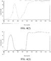
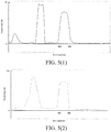
- the optical characteristics of the CF are as follows: optical characteristics of visible light wavebands remain unchanged, and in infrared light wavebands, infrared light with an infrared wavelength of ⁇ (850 nm+-50 nm) used by the fill light lamp passes.
- FIG. 4(1) is a schematic diagram of optical characteristics of a red filter before adjustment
- FIG. 4(2) is a schematic diagram of optical characteristics of a green filter before adjustment
- FIG. 4(3) is a schematic diagram of optical characteristics of a blue filter before adjustment
- FIG. 5(1) is a schematic diagram of optical characteristics of a red filter after adjustment
- FIG. 5(2) is a schematic diagram of optical characteristics of a green filter after adjustment
- FIG. 5(3) is a schematic diagram of optical characteristics of a blue filter after adjustment.
- the light-sensitive chip 200 senses a complicated spectral signal (visible light + infrared light), for the visible light, as the gain ratio of the signal processing circuit to the electric signals correspondingly generated by the light transmitting through the red, green and blue filters is A1: A2: A3, and at the same time, it is known to those skilled in the art that the red, green and blue visible light can be processed, to cause a component ratio of the red, green and blue visible light in the finally obtained image to be 1:1:1, so that the actual visible light color can be restored.
- a complicated spectral signal visible light + infrared light
- the intensity transmittance of the multiple red, green and blue filters of the color filter 100 to the particular-wavelength ( ⁇ ) infrared light is M1: M2(A1/A2): M3(A1/A3)
- the signal processing circuit when processed by the signal processing circuit, as the gain ratio of the signal processing circuit to the electric signals correspondingly generated by the light transmitting through the red, green and blue filters is A1: A2: A3, the infrared light is processed by the red, green and blue filters and the light-sensitive chip 200, and then the component ratio of red, green and blue colors under infrared in the obtained image is M1: M2: M3. Therefore, as long as the value of M1: M2: M3 is controlled in advance, color cast and the color cast degree of infrared light imaging can be controlled.
- the intensity transmittance of the multiple red, green and blue filters of the color filter 100 to the particular-wavelength ( ⁇ ) infrared light is 1: (A1/A2): (A1/A3)
- the signal processing circuit when processed by the signal processing circuit, as the gain ratio of the signal processing circuit to the electric signals correspondingly generated by the light transmitting through the red, green and blue filters is A1: A2: A3, the infrared light is processed by the red, green and blue filters and the light-sensitive chip 200, and then the component ratio of red, green and blue colors under infrared in the obtained image is 1:1:1; the ratio is gray scale of brightness, and thus incidence of the infrared light may not affect the restored color of the visible light.
- the image is brighter and has better definition.
- the light-sensitive chip 200 senses single infrared light (the wavelength is ⁇ ) emitted by the fill light lamp, because the CF allows the infrared light whose wavelength is ⁇ to transmit, the human eye cannot see an object clearly when only the fill light lamp is present in the evening, but the light-sensitive chip 200 still can sense the infrared light whose wavelength is ⁇ , after the infrared light passes through the red, green and blue filters whose intensity transmittance is 1: (A1/A2): (A1/A3), the intensity sensed by the light-sensitive units corresponding to the red, green and blue filters is 1: (A1/A2): (A1/A3), during processing of the signal processing circuit, the gain ratio of the signal processing circuit to the electric signals correspondingly generated by the light transmitting through the red, green and blue filters is A1: A2: A3, so that the component ratio of red, green and blue colors in the
- a sensing spectral range of the image sensor is wider than that of the human eye, and a silica-based material may be better sensitive to infrared rays of 940 nm.
- CMOS image sensor can provide a real color or a black-and-white image.
- the image output by the image sensor is also a redish image. The greater the value of M1 is, the redder the color of the finally obtained image is.
- the image output by the image sensor is also a greenish image. The greater the value of M2 is, the greener the color of the finally obtained image is.
- the image output by the image sensor is also a blueish image. The greater the value of M3 is, the bluer the color of the finally obtained image is.
- any color cast type can be selected according to user requirements in other embodiments of the present invention, as long as the ratio of the M value corresponding to each color is adjusted.
- the image output by the image sensor is also a light blueish image.
- M1: M2: M3 2:1:1.5
- the image output by the image sensor is also a light purpleish image.
- the image sensor according to the embodiment of the present invention can be applied in lots of fields, for example, if it is necessary to shoot a vintage-style picture in a certain application, this can be achieved by setting values of the M1, M2, ..., Mi, ..., Mj, ... and Mn to make the color of the shot picture light brownish, and then the vintage-style picture can be directly shot through the image sensor, thus avoiding problems such as image distortion caused by processing an image into a vintage style through an image processing technology and enhancing user experience.
- the gain ratios of the signal processing circuit corresponding to the image sensor of the same model to the electric signals corresponding to the light transmitting through the multiple n-color filters A1: A2: ...: Ai: ...: Aj: ...: An are the same.
- the image sensor according to the embodiment of the present invention achieves user-desired color cast or color cast degree by adjusting optical characteristics of a color filter, thus greatly increasing an application range of the image sensor and enhancing user experience.
- the image sensor 10 further includes: a micro lens 300.
- the micro lens 300 is located above the color filter 100, and the micro lens 300 is used for receiving and converging the incident light. Specifically, light passes through the micro lens 300, and the micro lens 300 converges and strengthens the light.
- the image sensor 10 may further include a light filter 400.
- the light filter 400 is located above the micro lens 300, used for filtering infrared light except the particular-wavelength infrared light, so that a filtering effect is better, and thus the effect of the shot image is also better.
- the light filter 400 may also be directly placed above the color filter 100.
- the present invention further proposes a monitoring system.
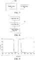
- FIG. 7 is a schematic structural diagram of a monitoring system according to one embodiment of the present invention.
- the monitoring system includes an electronic device 1000 and a fill light lamp 20.
- the electronic device 1000 has an image sensor 100, and the fill light lamp 20 emits particular-wavelength infrared light.
- the monitoring system according to the embodiment of the present invention can achieve user-desired color cast or color cast degree, thus greatly increasing an application range of the image sensor and enhancing user experience.
- FIG. 8 is a schematic structural diagram of an image sensor according to another embodiment of the present invention.
- the image sensor 30 includes: at least one light filter 500, a color filter 600 and a light-sensitive chip 700.
- the light filter 500 is used for filtering infrared light except the particular-wavelength infrared light.
- the light filter 500 allows visible light and the particular-wavelength infrared light to transmit.
- the color filter 600 is located below the light filter 500, wherein the color filter 600 includes multiple n-color filters, wherein each filter corresponds to one color, the multiple n-color filters are used for dividing visible light in incident light into n-color light, wherein n is a positive integer.
- the light-sensitive chip 700 is located below the color filter 600, wherein the light-sensitive chip 700 includes a signal processing circuit and multiple light-sensitive units one-to-one corresponding to the multiple n-color filters, the multiple light-sensitive units are respectively used for sensing intensity of light transmitting through the multiple n-color filters and generating electric signals corresponding to the light transmitting through the multiple n-color filters, the signal processing circuit is used for processing the electric signals for imaging, and a gain ratio of the signal processing circuit to the electric signals is A1: A2: ...: Ai: ...: Aj: ...: An, wherein an intensity transmittance of the multiple n-color filters of the color filter 600 to the particular-wavelength infrared light is M1: M2(A1/A2): ...: Mi(A1/Ai): ...: Mj(A1/Aj): ...: Mn(A1/An), and values of the M1, M2, ..., Mi, ..., Mj, ... and Mn are determined according to color
- the light filter 500 is an IR filter, and the light filter 500 is used for filtering infrared light except the particular-wavelength infrared light. That is, the light filter 500 allows visible light and the particular-wavelength infrared light to transmit. For example, the light filter 500 only allows visible light and infrared light whose wavelength is ⁇ (i.e., 850 nm+-50 nm), and light in other wavebands is cut off.
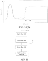
- FIG. 9 is a schematic diagram of optical characteristics of the light filter 500.
- the color cast includes a color cast type.
- a shot picture is redish, greenish or blueish in color.
- the color cast further includes a color cast degree.
- the Mi value of a filter corresponding to a target color cast type is greater than the Mj value of other filters.
- the color filter 600 includes red, green and blue filters is merely an example made for facilitating description, the color filter 600 may further include filters in other colors, for example, the color filter 600 may include cyan, carmine (or magenta) and yellow filters, and the color filter 600 may include red, green, blue and white filters.
- the light reaches the color filter 600 (which can be abbreviated as CF) which has light transmission selectivity (that is, only particular light is allowed to pass) and intensity attenuation (that is, intensity of passing light may decrease).
- the color filter 600 includes multiple red, green and blue filters used for dividing visible light in incident light into three primary colors, red, green and blue.
- the light-sensitive chip 700 conducts imaging according to light transmitting through the red, green and blue filters of the color filter 600.
- the red, green and blue filters are arranged in a certain order to form an array.
- the signal processing circuit processes corresponding electric signals in an order of arrangement of the filters, to restore actual colors and form pictures. More specifically, the light transmitting through the red, green and blue filters of the color filter 600 reaches the underlying light-sensitive unit, the light signals are converted to electric signals, and the electric signals can generate an image after being processed by the signal processing circuit, wherein the light-sensitive units may be photosensitive diodes.
- the optical characteristics of the color filter 600 are adjusted, to cause the intensity transmittance of the multiple red, green and blue filters of the color filter 600 to the particular-wavelength (e.g., 850 nm+-50 nm) infrared light to be M1: M2(A1/A2): M3(A1/A3).
- the light filter 500 can filter infrared light except the particular-wavelength infrared light, the intensity transmittance of infrared light in other wavelength ranges does not need to be specially adjusted.
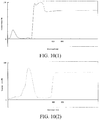
- FIG. 10(1), FIG. 10(2) and FIG. 10(3) are respectively schematic diagrams of optical characteristics of red, green and blue filters, wherein the dotted line indicates that the value may be arbitrary.
- the intensity transmittance of all the infrared light as M1: M2(A1/A2): M3(A1/A3); in fact, the infrared light in other wavelength ranges except the particular-wavelength infrared light can be adjusted arbitrarily.
- the gain ratio of the signal processing circuit to the electric signals corresponding to the light transmitting through the multiple n-color filters A1: A2: ...: Ai: ...: Aj: ...: An is obtained according to the intensity transmittance of the multiple n-color filters of the color filter to the particular-wavelength infrared light.
- the intensity transmittance of the multiple n-color filters of the color filter to the particular-wavelength infrared light is determined as M1: M2(A1/A2): ...: Mi(A1/Ai): ...: Mj(A1/Aj): ...: Mn(A1/An), wherein values of the M1, M2, ..., Mi, ..., Mj, ...
- the gain ratio of the signal processing circuit to the electric signals is determined according to the intensity transmittance of the multiple n-color filters of the color filter to the particular-wavelength infrared light, that is, the gain ratio of the signal processing circuit to the electric signals A1: A2: ...: Ai: ...: Aj: ...: An is obtained through testing.
- the red, green and blue filters are still taken as an example; in the sun, infrared light is filtered, and only visible light remains; at this point, the red, green and blue light-sensitive units sense intensity of the visible light, which is converted to electric signals and then will be processed by the signal processing circuit, and then an image in a pure color is output; at this point, the gain ratio of the signal processing circuit to the electric signals correspondingly generated by red, green and blue visible light is A1: A2: A3.
- the red, green and blue visible light can be processed, to cause a component ratio of the red, green and blue visible light in the finally obtained image to be 1:1:1, thus obtaining an image whose color is the same as that of an actual object.
- a fill light lamp in a specific application environment of the image sensor, can be selected to fill light for the image sensor, and the fill light lamp emits particular-wavelength infrared light.
- the particular wavelength matches the wavelength of the infrared light emitted by the selected fill light lamp. That is, the light filter 500 and the selected fill light lamp cooperate for use. Specifically, for example, the wavelength of the infrared light emitted by the fill light lamp is ⁇ , and the light filter 500 allows the infrared light whose wavelength is ⁇ to pass and filter other-wavelength infrared light.
- the light-sensitive chip 700 senses a complicated spectral signal (visible light + infrared light), for the visible light, as the gain ratio of the signal processing circuit to the electric signals correspondingly generated by the light transmitting through the red, green and blue filters is A1: A2: A3, and at the same time, it is known to those skilled in the art that the red, green and blue visible light can be processed, to cause a component ratio of the red, green and blue visible light in the finally obtained image to be 1:1:1, so that the actual visible light color can be restored.
- a complicated spectral signal visible light + infrared light
- the intensity transmittance of the multiple red, green and blue filters of the color filter 600 to the particular-wavelength ( ⁇ ) infrared light is M1: M2(A1/A2): M3(A1/A3)
- the signal processing circuit when processed by the signal processing circuit, as the gain ratio of the signal processing circuit to the electric signals correspondingly generated by the light transmitting through the red, green and blue filters is A1: A2: A3, the infrared light is processed by the red, green and blue filters and the light-sensitive chip 700, and then the component ratio of red, green and blue colors under infrared in the obtained image is M1: M2: M3. Therefore, as long as the value of M1: M2: M3 is controlled in advance, color cast and the color cast degree of infrared light imaging can be controlled.
- the intensity transmittance of the multiple red, green and blue filters of the color filter 600 to the particular-wavelength ( ⁇ ) infrared light is 1: (A1/A2): (A1/A3)
- the signal processing circuit when processed by the signal processing circuit, as the gain ratio of the signal processing circuit to the electric signals correspondingly generated by the light transmitting through the red, green and blue filters is A1: A2: A3, the infrared light is processed by the red, green and blue filters and the light-sensitive chip 700, and then the component ratio of red, green and blue colors under infrared in the obtained image is 1:1:1; the ratio is gray scale of brightness, and thus incidence of the infrared light may not affect the restored color of the visible light.
- the image is brighter and has better definition.
- the light-sensitive chip 700 senses single infrared light (the wavelength is ⁇ ) emitted by the fill light lamp, because the color filter 500 allows the infrared light whose wavelength is ⁇ to transmit, the human eye cannot see an object clearly when only the fill light lamp is present in the evening, but the light-sensitive chip 700 still can sense the infrared light whose wavelength is ⁇ , after the infrared light passes through the red, green and blue filters whose intensity transmittance is 1: (A1/A2): (A1/A3), the intensity sensed by the light-sensitive units corresponding to the red, green and blue filters is 1: (A1/A2): (A1/A3), during processing of the signal processing circuit, the gain ratio of the signal processing circuit to the electric signals correspondingly generated by the light transmitting through the red, green and blue filters is A1: A2: A3, so that the component ratio of red, green and blue colors in
- a sensing spectral range of the image sensor is wider than that of the human eye, and a silica-based material may be better sensitive to infrared rays of 940 nm.
- CMOS image sensor can provide a real color or a black-and-white image.
- the image output by the image sensor is also a redish image. The greater the value of M1 is, the redder the color of the finally obtained image is.
- the image output by the image sensor is also a greenish image. The greater the value of M2 is, the greener the color of the finally obtained image is.
- the image output by the image sensor is also a blueish image. The greater the value of M3 is, the bluer the color of the finally obtained image is.
- any color cast type can be selected according to user requirements in other embodiments of the present invention, as long as the ratio of the M value corresponding to each color is adjusted.
- the light-sensitive chip 700 senses a complicated spectral signal (visible light + infrared light)
- the image output by the image sensor is also a light blueish image.
- M1: M2: M3 2:1:1.5
- the image output by the image sensor is also a light purpleish image.
- the image sensor according to the embodiment of the present invention can be applied in lots of fields, for example, if it is necessary to shoot a vintage-style picture in a certain application, this can be achieved by setting values of the M1, M2, ..., Mi, ..., Mj, ... and Mn to make the color of the shot picture light brownish, and then the vintage-style picture can be directly shot through the image sensor, thus avoiding problems such as image distortion caused by processing an image into a vintage style through an image processing technology and enhancing user experience.
- the gain ratios of the signal processing circuit corresponding to the image sensor of the same model to the electric signals corresponding to the light transmitting through the multiple n-color filters A1: A2: ...: Ai: ...: Aj: ...: An are the same.
- the image sensor according to the embodiment of the present invention achieves user-desired color cast or color cast degree by adjusting optical characteristics of a color filter, thus greatly increasing an application range of the image sensor and enhancing user experience.
- the image sensor 30 further includes: a micro lens 800, wherein the micro lens 800 is located between the light filter or light filter assembly 500 and the color filter 600, and the micro lens 800 is used for receiving and converging the incident light. Specifically, light passes through the micro lens 800, and the micro lens 800 converges and strengthens the light.
- the present invention further proposes a monitoring system.
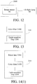
- FIG. 12 is a schematic structural diagram of a monitoring system according to one embodiment of the present invention.
- the monitoring system includes an electronic device 2000 and a fill light lamp 40.
- the electronic device 2000 has an image sensor 30, and the fill light lamp 40 emits particular-wavelength infrared light.
- the monitoring system according to the embodiment of the present invention can achieve user-desired color cast or color cast degree, thus greatly increasing an application range of the image sensor and enhancing user experience.
- FIG. 13 is a schematic structural diagram of a monitoring system according to one embodiment of the present invention.
- the image sensor according to the embodiment of the present invention is a CMOS image sensor.
- the image sensor 310 includes: a color filter 3100, and a light-sensitive chip 3200.
- the color filter 3100 allows part of the visible light to transmit; for infrared wavebands, the color filter 3100 only allows particular-wavelength infrared light to pass, an intensity transmittance of the color filter 3100 to the particular-wavelength infrared light is adjustable, and the color filter 3100 includes multiple n-color filters, wherein each filter corresponds to one color, the multiple n-color filters are used for dividing visible light in incident light into n-color light, wherein n is a positive integer.
- the color filter 3100 allows part of the visible light to transmit, which means that the color filter 3100 includes multiple-color filters, for example, when the color filter 3100 includes red, green and blue filters, the red filter only allows red light in the visible light to transmit, the green filter only allows green light in the visible light to transmit, and the blue filter only allows blue light in the visible light to transmit.
- the light-sensitive chip 3200 is located below the color filter 3100, the light-sensitive chip 3200 includes a signal processing circuit and multiple light-sensitive units one-to-one corresponding to the multiple n-color filters, the multiple light-sensitive units are respectively used for sensing intensity of light transmitting through the multiple n-color filters and generating electric signals corresponding to the light transmitting through the multiple n-color filters, the signal processing circuit is used for processing the electric signals for imaging, and a gain ratio of the signal processing circuit to the electric signals is M1A1: M2A2: ...: MiAi: ...: MjAj: ...: MnAn, wherein values of the M1, M2, ..., Mi, ..., Mj, ...
- i and j are integers greater than or equal to 1 and less than or equal to n, and i ⁇ j, wherein an intensity transmittance of the multiple n-color filters of the color filter to the particular-wavelength infrared light is 1: (A1/A2): ...: (A1/Ai): ...: (A1/Aj): ...: (A1/An).
- the color cast includes a color cast type.
- a shot picture is redish, greenish or blueish in color.
- the color cast further includes a color cast degree.
- the Mi value of a filter corresponding to a target color cast type is greater than the Mj value of other filters.
- the color filter 3100 includes red, green and blue filters is merely an example made for facilitating description, the color filter 3100 may further include filters in other colors, for example, the color filter 100 may include cyan, carmine (or magenta) and yellow filters, and the color filter 3100 may include red, green, blue and white filters.
- the light reaches the color filter 3100 (which can be abbreviated as CF) which has light transmission selectivity (that is, only particular light is allowed to pass) and intensity attenuation (that is, intensity of passing light may decrease).
- the color filter 3100 includes multiple red, green and blue filters used for dividing visible light in incident light into three primary colors, red, green and blue, and for infrared light wavebands, the red, green and blue filters only allow particular-wavelength infrared light (e.g., infrared light whose wavelength is 850 nm+-50 nm) to pass.
- the multiple light-sensitive units are respectively used for sensing intensity of light transmitting through the multiple n-color filters and generating electric signals corresponding to the light transmitting through the multiple n-color filters, and the signal processing circuit is used for processing the electric signals for imaging.
- the light-sensitive units may be photosensitive diodes.
- the light-sensitive chip 3200 conducts imaging according to light transmitting through the red, green and blue filters of the color filter 3100.
- the signal processing circuit processes corresponding electric signals in an order of arrangement of the filters, to restore actual colors and form pictures. More specifically, the light transmitting through the red, green and blue filters of the color filter 3100 passes through the photosensitive diodes, the light signals are converted to electric signals, and the electric signals can generate an image after being processed by the signal processing circuit.
- the gain ratio of the signal processing circuit to the electric signals corresponding to the light transmitting thoruhg the multiple n-color filters M1A1: M2A2: ...: MiAi: ...: MjAj: ...: MnAn is obtained according to the intensity transmittance of the multiple n-color filters of the color filter to the particular-wavelength infrared light, wherein values of the M1, M2, ..., Mi, ..., Mj, ... and Mn are determined according to color cast required by the image sensor.
- the intensity transmittance of the multiple n-color filters of the color filter to the particular-wavelength infrared light is determined as 1: (A1/A2): ...: (A1/Ai): ...: (A1/Aj): ...: (A1/An)
- the gain ratio of the signal processing circuit to the electric signals is determined according to the intensity transmittance of the multiple n-color filters of the color filter to the particular-wavelength infrared light, that is, the gain ratio of the signal processing circuit to the electric signals M1A1: M2A2: ...: MiAi: ...: MjAj: ...: MnAn is obtained through testing.
- the red, green and blue filters are still taken as an example; in the sun, infrared light is filtered, and only visible light remains; at this point, the red, green and blue light-sensitive units sense intensity of the visible light, which is converted to electric signals and then will be processed by the signal processing circuit, and then an image in a pure color is output; at this point, the gain ratio of the signal processing circuit to the electric signals correspondingly generated by red, green and blue visible light is M1A1: M2A2: M3A3.
- the red, green and blue visible light can be processed, to cause a component ratio of the red, green and blue visible light in the finally obtained image to be 1:1:1, thus obtaining an image whose color is the same as that of an actual object.
- a fill light lamp in a specific application environment of the image sensor, can be selected to fill light for the image sensor, and the fill light lamp emits particular-wavelength infrared light.
- the particular wavelength matches the wavelength of the infrared light emitted by the selected fill light lamp.
- the color filter 3100 only allows particular-wavelength infrared light to transmit, and other-wavelength infrared light cannot transmit through the color filter 3100.
- the wavelength of the infrared light emitted by the fill light lamp is ⁇ (e.g., a fill light lamp of 850 nm+-50 nm is used).
- ⁇ e.g., a fill light lamp of 850 nm+-50 nm is used.
- the optical characteristics of the CF are as follows: optical characteristics of visible light wavebands remain unchanged, and in infrared light wavebands, infrared light with an infrared wavelength of ⁇ (850 nm+-50 nm) used by the fill light lamp passes.
- the intensity transmittance of the multiple red, green and blue filters of the color filter 3100 to the particular-wavelength ( ⁇ ) infrared light is 1: (A1/A2): (A1/A3).
- the light-sensitive chip 3200 senses a complicated spectral signal (visible light + infrared light), for the visible light, as the gain ratio of the signal processing circuit to the electric signals corresponding to the light transmitting through the red, green and blue filters is M1A1: M2A2: M3A3, and at the same time, it is known to those skilled in the art that the red, green and blue visible light can be processed, to cause a component ratio of the red, green and blue visible light in the finally obtained image to be 1:1:1, so that the actual visible light color can be restored.
- a complicated spectral signal visible light + infrared light
- the intensity transmittance of the multiple red, green and blue filters of the color filter 3100 to the particular-wavelength ( ⁇ ) infrared light is 1: (A1/A2): (A1/A3)
- the signal processing circuit when processed by the signal processing circuit, as the gain ratio of the signal processing circuit to the electric signals correspondingly generated by the light transmitting through the red, green and blue filters is M1A1: M2A2: M3A3, the infrared light is processed by the red, green and blue filters and the light-sensitive chip 200, and then the component ratio of red, green and blue colors under infrared in the obtained image is M1: M2: M3. Therefore, as long as the value of M1: M2: M3 is controlled in advance, color cast and the color cast degree of infrared light imaging can be controlled.
- the intensity transmittance of the multiple red, green and blue filters of the color filter 3100 to the particular-wavelength ( ⁇ ) infrared light is 1: (A1/A2): (A1/A3)
- the signal processing circuit when processed by the signal processing circuit, as the gain ratio of the signal processing circuit to the electric signals correspondingly generated by the light transmitting through the red, green and blue filters is A1: A2: A3, the infrared light is processed by the red, green and blue filters and the light-sensitive chip 3200, and then the component ratio of red, green and blue colors under infrared in the obtained image is 1:1:1; the ratio is gray scale of brightness, and thus incidence of the infrared light may not affect the restored color of the visible light.
- the image is brighter and has better definition.
- the light-sensitive chip 3200 senses single infrared light (the wavelength is ⁇ ) emitted by the fill light lamp, because the CF allows the infrared light whose wavelength is ⁇ to transmit, the human eye cannot see an object clearly when only the fill light lamp is present in the evening, but the light-sensitive chip 3200 still can sense the infrared light whose wavelength is ⁇ , after the infrared light passes through the red, green and blue filters whose intensity transmittance is 1: (A1/A2): (A1/A3), the intensity sensed by the light-sensitive units corresponding to the red, green and blue filters is 1: (A1/A2): (A1/A3), during processing of the signal processing circuit, the gain ratio of the signal processing circuit to the electric signals correspondingly generated by the light transmitting through the red, green and blue filters is A1: A2: A3, so that the component ratio of red, green and blue colors
- a sensing spectral range of the image sensor is wider than that of the human eye, and a silica-based material may be better sensitive to infrared rays of 940 nm.
- CMOS image sensor can provide a real color or a black-and-white image.
- the image output by the image sensor is also a redish image. The greater the value of M1 is, the redder the color of the finally obtained image is.
- the image output by the image sensor is also a greenish image. The greater the value of M2 is, the greener the color of the finally obtained image is.
- the image output by the image sensor is also a blueish image. The greater the value of M3 is, the bluer the color of the finally obtained image is.
- any color cast type can be selected according to user requirements in other embodiments of the present invention, as long as the ratio of the M value corresponding to each color is adjusted.
- the light-sensitive chip 3200 senses a complicated spectral signal (visible light + infrared light)
- the image output by the image sensor is also a light blueish image.
- M1: M2: M3 2:1:1.5
- the image output by the image sensor is also a light purpleish image.
- the image sensor according to the embodiment of the present invention can be applied in lots of fields, for example, if it is necessary to shoot a vintage-style picture in a certain application, this can be achieved by setting values of the M1, M2, ..., Mi, ..., Mj, ... and Mn to make the color of the shot picture light brownish, and then the vintage-style picture can be directly shot through the image sensor, thus avoiding problems such as image distortion caused by processing an image into a vintage style through an image processing technology and enhancing user experience.
- the gain ratio of the signal processing circuit corresponding to the image sensor of the same model to the electric signals corresponding to the light transmitting through the multiple n-color filters M1A1: M2A2: ...: MiAi: ...: MjAj: ...: MnAn is the same.
- the image sensor according to the embodiment of the present invention achieves user-desired color cast or color cast degree by adjusting optical characteristics of a color filter, thus greatly increasing an application range of the image sensor and enhancing user experience.
- the image sensor 310 further includes: a micro lens 3300.
- the micro lens 3300 is located above the color filter 3100, and the micro lens 3300 is used for receiving and converging the incident light. Specifically, light passes through the micro lens 3300, and the micro lens 3300 converges and strengthens the light.
- the image sensor 310 may further include a light filter 3400.
- the light filter 3400 is located above the micro lens 3300, used for filtering infrared light except the particular-wavelength infrared light, so that a filtering effect is better, and thus the effect of the shot image is also better.
- the light filter 3400 may also be directly placed above the color filter 3100.
- the present invention further proposes a monitoring system.
- FIG. 15 is a schematic structural diagram of a monitoring system according to one embodiment of the present invention.
- the monitoring system includes an electronic device 31000 and a fill light lamp 320.
- the electronic device 31000 has an image sensor 310, and the fill light lamp 320 emits particular-wavelength infrared light.
- the monitoring system according to the embodiment of the present invention can achieve user-desired color cast or color cast degree, thus greatly increasing an application range of the image sensor and enhancing user experience.
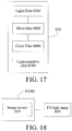
- FIG. 16 is a schematic structural diagram of an image sensor according to another embodiment of the present invention.
- the image sensor 630 includes: at least one light filter 6500, a color filter 6600 and a light-sensitive chip 6700.
- the light filter 6500 is used for filtering infrared light except the particular-wavelength infrared light.
- the light filter 6500 allows visible light and the particular-wavelength infrared light to transmit.
- the color filter 6600 is located below the light filter 6500, wherein the color filter 6600 includes multiple n-color filters, wherein each filter corresponds to one color, the multiple n-color filters are used for dividing visible light in incident light into n-color light, wherein n is a positive integer.
- the light-sensitive chip 6700 is located below the color filter 6600, wherein the light-sensitive chip 6700 includes a signal processing circuit and multiple light-sensitive units one-to-one corresponding to the multiple n-color filters, the multiple light-sensitive units are respectively used for sensing intensity of light transmitting through the multiple n-color filters and generating electric signals corresponding to the light transmitting through the multiple n-color filters, the signal processing circuit is used for processing the electric signals for imaging, and a gain ratio of the signal processing circuit to the electric signals is M1A1: M2A2: ...: MiAi: ...: MjAj: ...: MnAn, wherein values of the M1, M2, ..., Mi, ..., Mj, ...
- i and j are integers greater than or equal to 1 and less than or equal to n, and i ⁇ j, wherein an intensity transmittance of the multiple n-color filters of the color filter 6600 to the particular-wavelength infrared light is 1: (A1/A2): ...: (A1/Ai): ...: (A1/Aj): ...: (A1/An).
- the light filter 6500 is an IR filter, and the light filter 6500 is used for filtering infrared light except the particular-wavelength infrared light. That is, the light filter 6500 allows visible light and the particular-wavelength infrared light to transmit. For example, the light filter 6500 only allows visible light and infrared light whose wavelength is ⁇ (i.e., 850 nm+-50 nm), and light in other wavebands is cut off.
- ⁇ i.e., 850 nm+-50 nm
- the color cast includes a color cast type.
- a shot picture is redish, greenish or blueish in color.
- the color cast further includes a color cast degree.
- the Mi value of a filter corresponding to a target color cast type is greater than the Mj value of other filters.
- the color filter 6600 includes red, green and blue filters is merely an example made for facilitating description, the color filter 6600 may further include filters in other colors, for example, the color filter 6600 may include cyan, carmine (or magenta) and yellow filters, and the color filter 6600 may include red, green, blue and white filters.
- the light-sensitive chip 6700 conducts imaging according to light transmitting through the red, green and blue filters of the color filter 6600.
- the red, green and blue filters are arranged in a certain order to form an array.
- the signal processing circuit processes corresponding electric signals in an order of arrangement of the filters, to restore actual colors and form pictures. More specifically, the light transmitting through the red, green and blue filters of the color filter 6600 reaches the underlying light-sensitive unit, the light signals are converted to electric signals, and the electric signals can generate an image after being processed by the signal processing circuit, wherein the light-sensitive units may be photosensitive diodes.
- the optical characteristics of the color filter 6600 are adjusted, to cause the intensity transmittance of the multiple red, green and blue filters of the color filter 6600 to the particular-wavelength (e.g., 850 nm+-50 nm) infrared light to be 1: (A1/A2): (A1/A3).
- the light filter 6500 can filter infrared light except the particular-wavelength infrared light, the intensity transmittance of infrared light in other wavelength ranges does not need to be specially adjusted.
- the intensity transmittance of all the infrared light as 1: (A1/A2): (A1/A3); in fact, the infrared light in other wavelength ranges except the particular-wavelength infrared light can be adjusted arbitrarily.
- the gain ratio of the signal processing circuit to the electric signals corresponding to the light transmitting through the multiple n-color filters M1A1: M2A2: ...: MiAi: ...: MjAj: ...: MnAn is obtained according to the intensity transmittance of the multiple n-color filters of the color filter to the particular-wavelength infrared light.
- the intensity transmittance of the multiple n-color filters of the color filter to the particular-wavelength infrared light is determined as 1: (A1/A2): ....
- the gain ratio of the signal processing circuit to the electric signals is determined according to the intensity transmittance of the multiple n-color filters of the color filter to the particular-wavelength infrared light, that is, the gain ratio of the signal processing circuit to the electric signals M1A1: M2A2: ...: MiAi: ...: MjAj: ...: MnAn is obtained through testing.
- the red, green and blue filters are still taken as an example; in the sun, infrared light is filtered, and only visible light remains; at this point, the red, green and blue light-sensitive units sense intensity of the visible light, which is converted to electric signals and then will be processed by the signal processing circuit, and then an image in a pure color is output; at this point, the gain ratio of the signal processing circuit to the electric signals correspondingly generated by red, green and blue visible light is M1A1: M2A2: M3A3.
- the red, green and blue visible light can be processed, to cause a component ratio of the red, green and blue visible light in the finally obtained image to be 1:1:1, thus obtaining an image whose color is the same as that of an actual object.
- a fill light lamp in a specific application environment of the image sensor, can be selected to fill light for the image sensor, and the fill light lamp emits particular-wavelength infrared light.
- the particular wavelength matches the wavelength of the infrared light emitted by the selected fill light lamp. That is, the light filter 6500 and the selected fill light lamp cooperate for use. Specifically, for example, the wavelength of the infrared light emitted by the fill light lamp is ⁇ , and at least one light filter 6500 allows the infrared light whose wavelength is ⁇ to pass and filter other-wavelength infrared light.
- the light-sensitive chip 6700 senses a complicated spectral signal (visible light + infrared light), for the visible light, as the gain ratio of the signal processing circuit to the electric signals corresponding to the light transmitting through the red, green and blue filters is M1A1: M2A2: M3A3, and at the same time, it is known to those skilled in the art that the red, green and blue visible light can be processed, to cause a component ratio of the red, green and blue visible light in the finally obtained image to be 1:1:1, so that the actual visible light color can be restored.
- a complicated spectral signal visible light + infrared light
- the intensity transmittance of the multiple red, green and blue filters of the color filter 6600 to the particular-wavelength ( ⁇ ) infrared light is 1: (A1/A2): (A1/A3)
- the signal processing circuit when processed by the signal processing circuit, as the gain ratio of the signal processing circuit to the electric signals correspondingly generated by the light transmitting through the red, green and blue filters is M1A1: M2A2: M3A3, the infrared light is processed by the red, green and blue filters and the light-sensitive chip 6700, and then the component ratio of red, green and blue colors under infrared in the obtained image is M1: M2: M3. Therefore, as long as the value of M1: M2: M3 is controlled in advance, color cast and the color cast degree of infrared light imaging can be controlled.
- the intensity transmittance of the multiple red, green and blue filters of the color filter 6600 to the particular-wavelength ( ⁇ ) infrared light is 1: (A1/A2): (A1/A3)
- the signal processing circuit when processed by the signal processing circuit, as the gain ratio of the signal processing circuit to the electric signals correspondingly generated by the light transmitting through the red, green and blue filters is A1: A2: A3, the infrared light is processed by the red, green and blue filters and the light-sensitive chip 6700, and then the component ratio of red, green and blue colors under infrared in the obtained image is 1:1:1; the ratio is gray scale of brightness, and thus incidence of the infrared light may not affect the restored color of the visible light.
- the image is brighter and has better definition.
- the light-sensitive chip 6700 senses single infrared light (the wavelength is ⁇ ) emitted by the fill light lamp, because the color filter 6500 allows the infrared light whose wavelength is ⁇ to transmit, the human eye cannot see an object clearly when only the fill light lamp is present in the evening, but the light-sensitive chip 6700 still can sense the infrared light whose wavelength is ⁇ , after the infrared light passes through the red, green and blue filters whose intensity transmittance is 1: (A1/A2): (A1/A3), the intensity sensed by the light-sensitive units corresponding to the red, green and blue filters is 1: (A1/A2): (A1/A3), during processing of the signal processing circuit, the gain ratio of the signal processing circuit to the electric signals correspondingly generated by the light transmitting through the red, green and blue filters is A1: A2: A3, so that the component ratio of red, green and
- a sensing spectral range of the image sensor is wider than that of the human eye, and a silica-based material may be better sensitive to infrared rays of 940 nm.
- CMOS image sensor can provide a real color or a black-and-white image.
- the image output by the image sensor is also a redish image. The greater the value of M1 is, the redder the color of the finally obtained image is.
- the image output by the image sensor is also a greenish image. The greater the value of M2 is, the greener the color of the finally obtained image is.
- the image output by the image sensor is also a blueish image. The greater the value of M3 is, the bluer the color of the finally obtained image is.
- any color cast type can be selected according to user requirements in other embodiments of the present invention, as long as the ratio of the M value corresponding to each color is adjusted.
- the light-sensitive chip 6700 senses a complicated spectral signal (visible light + infrared light)
- the image output by the image sensor is also a light blueish image.
- M1: M2: M3 2:1:1.5
- the image output by the image sensor is also a light purpleish image.
- the image sensor according to the embodiment of the present invention can be applied in lots of fields, for example, if it is necessary to shoot a vintage-style picture in a certain application, this can be achieved by setting values of the M1, M2, ..., Mi, ..., Mj, ... and Mn to make the color of the shot picture light brownish, and then the vintage-style picture can be directly shot through the image sensor, thus avoiding problems such as image distortion caused by processing an image into a vintage style through an image processing technology and enhancing user experience.
- the gain ratios of the signal processing circuit corresponding to the image sensor of the same model to the electric signals corresponding to the light transmitting through the multiple n-color filters M1A1: M2A2: ...: MiAi: ...: MjAj: ...: MnAn are the same.
- the image sensor according to the embodiment of the present invention achieves user-desired color cast or color cast degree by adjusting optical characteristics of a color filter and using a light filter having particular optical characteristics, thus greatly increasing an application range of the image sensor and enhancing user experience.
- the image sensor 630 further includes: a micro lens 6800, wherein the micro lens 6800 is located between the light filter or light filter assembly 6500 and the color filter 6600, and the micro lens 6800 is used for receiving and converging the incident light. Specifically, light passes through the micro lens 6800, and the micro lens 6800 converges and strengthens the light.
- the present invention further proposes a monitoring system.
- FIG. 18 is a schematic structural diagram of a monitoring system according to one embodiment of the present invention.
- the monitoring system includes an electronic device 62000 and a fill light lamp 640.
- the electronic device 62000 has an image sensor 630, and the fill light lamp 640 emits particular-wavelength infrared light.
- the monitoring system according to the embodiment of the present invention can achieve user-desired color cast or color cast degree, thus greatly increasing an application range of the image sensor and enhancing user experience.
- a method for designing an image sensor according to an embodiment of the present invention can control influences of infrared light on the imaging color according to requirements of actual applications, thus greatly increasing the application range of the image sensor.
- the present invention further proposes an image sensor.
- the image sensor is an image sensor formed with the method for designing an image sensor according to the embodiment of the present invention.
- the image sensor according to the embodiment of the present invention can design influences of infrared light on the imaging color according to requirements of actual applications, thus greatly increasing the application range of the image sensor.
- first and second are only used for description but cannot be understood as indicating or implying relative importance or implicitly indicating the number of the indicated technical feature.
- the features defined with “first” and “second” can explicitly or implicitly include at least one of the features.
- the meaning of “multiple” is at least two, for example, two, three or the like, unless otherwise definitely and specifically defined.
- the terms “install”, “connected with”, “connect” and “fix” should be understood in a broad sense, for example, it may be a fixed connection, a detachable connection or an integral connection; may be a mechanical connection or an electrical connection; may be a direct connection or a connection through an intermediate medium, and may be communication inside two elements or an interaction relationship of two elements, unless otherwise explicitly defined.
- install may be a fixed connection, a detachable connection or an integral connection
- the specific meanings of the terms in the present invention can be understood according to specific situations.
- the first feature being “up” or “down” the second feature may be that the first and second features are in direct contact, or the first and second features are in direct contact through an intermediate medium.
- the first feature being “above”, “over” and “on” the second feature may be that the first feature is directly over or obliquely over the second feature, or merely indicates that the level height of the first feature is higher than that of the second feature.
- the first feature being “below”, “beneath” and “under” the second feature may be that the first feature is directly beneath or obliquely beneath the second feature, or merely indicates that the level height of the first feature is less than that of the second feature.
Landscapes
- Engineering & Computer Science (AREA)
- Multimedia (AREA)
- Signal Processing (AREA)
- Color Television Image Signal Generators (AREA)
- Solid State Image Pick-Up Elements (AREA)
- Optical Filters (AREA)
Applications Claiming Priority (2)
| Application Number | Priority Date | Filing Date | Title |
|---|---|---|---|
| CN201410146621.0A CN104980667B (zh) | 2014-04-13 | 2014-04-13 | 图像传感器和监控系统 |
| PCT/CN2015/075875 WO2015158211A1 (zh) | 2014-04-13 | 2015-04-03 | 图像传感器和监控系统 |
Publications (2)
| Publication Number | Publication Date |
|---|---|
| EP3133811A1 true EP3133811A1 (de) | 2017-02-22 |
| EP3133811A4 EP3133811A4 (de) | 2017-11-22 |
Family
ID=54276717
Family Applications (1)
| Application Number | Title | Priority Date | Filing Date |
|---|---|---|---|
| EP15780031.9A Withdrawn EP3133811A4 (de) | 2014-04-13 | 2015-04-03 | Bildsensor und überwachungssystem |
Country Status (5)
| Country | Link |
|---|---|
| US (1) | US20170148842A1 (de) |
| EP (1) | EP3133811A4 (de) |
| CN (1) | CN104980667B (de) |
| TW (1) | TWI554109B (de) |
| WO (1) | WO2015158211A1 (de) |
Families Citing this family (6)
| Publication number | Priority date | Publication date | Assignee | Title |
|---|---|---|---|---|
| US9952156B2 (en) | 2015-06-30 | 2018-04-24 | The United States Of America As Represented By The Secretary Of The Navy | Native fluorescence imaging direct push probe |
| US20170064220A1 (en) * | 2015-08-25 | 2017-03-02 | United States Government As Represented By The Secretary Of The Navy | Hyperspectral/Multispectral Imaging Direct Push Probe |
| CN110868509B (zh) * | 2018-08-28 | 2022-02-18 | 浙江大华技术股份有限公司 | 一种调整感光芯片板的方法和设备 |
| WO2020043116A1 (en) | 2018-08-28 | 2020-03-05 | Zhejiang Dahua Technology Co., Ltd. | Systems and methods for adjusting position of photosensitive chip of image acquisition device |
| CN109672828B (zh) * | 2019-01-04 | 2021-09-07 | 深圳英飞拓科技股份有限公司 | 基于光路白平衡的低照度提升装置及低照度提升方法 |
| CN111308239B (zh) * | 2020-02-19 | 2022-04-05 | 上海迈内能源科技有限公司 | 一种用于gis状态在线监测的无线监测系统 |
Family Cites Families (19)
| Publication number | Priority date | Publication date | Assignee | Title |
|---|---|---|---|---|
| JP4311988B2 (ja) * | 2003-06-12 | 2009-08-12 | アキュートロジック株式会社 | 固体撮像素子用カラーフィルタおよびこれを用いたカラー撮像装置 |
| JP3922238B2 (ja) * | 2003-10-22 | 2007-05-30 | ソニー株式会社 | 光量制御装置およびカメラ装置 |
| JP2006109120A (ja) * | 2004-10-06 | 2006-04-20 | Funai Electric Co Ltd | 赤外線撮像装置 |
| JP2006217441A (ja) * | 2005-02-07 | 2006-08-17 | Sanyo Electric Co Ltd | 色信号処理方法 |
| CN1971927B (zh) * | 2005-07-21 | 2012-07-18 | 索尼株式会社 | 物理信息获取方法、物理信息获取装置和半导体器件 |
| US7923801B2 (en) * | 2007-04-18 | 2011-04-12 | Invisage Technologies, Inc. | Materials, systems and methods for optoelectronic devices |
| JP2009253579A (ja) * | 2008-04-04 | 2009-10-29 | Panasonic Corp | 撮像装置、画像処理装置及び画像処理方法並びに画像処理プログラム |
| JP5178458B2 (ja) * | 2008-10-31 | 2013-04-10 | キヤノン株式会社 | 固体撮像装置、撮像システム、および、固体撮像装置の駆動方法 |
| JP2010206678A (ja) * | 2009-03-05 | 2010-09-16 | Panasonic Corp | 固体撮像装置、撮像モジュール、及び撮像システム |
| US9183425B2 (en) * | 2009-04-09 | 2015-11-10 | Hand Held Products, Inc. | Image sensor pixel array having output response curve including logarithmic pattern for image sensor based terminal |
| US8619143B2 (en) * | 2010-03-19 | 2013-12-31 | Pixim, Inc. | Image sensor including color and infrared pixels |
| JP5834386B2 (ja) * | 2010-08-20 | 2015-12-24 | ソニー株式会社 | 光学センサ、レンズモジュール、およびカメラモジュール |
| US8408821B2 (en) * | 2010-10-12 | 2013-04-02 | Omnivision Technologies, Inc. | Visible and infrared dual mode imaging system |
| TWI434404B (zh) * | 2010-12-07 | 2014-04-11 | Ind Tech Res Inst | 彩色濾光片與影像感測器 |
| JP2013041878A (ja) * | 2011-08-11 | 2013-02-28 | Sony Corp | 撮像装置およびカメラモジュール |
| CN102957917B (zh) * | 2011-08-30 | 2016-03-30 | 比亚迪股份有限公司 | 一种像素阵列、摄像头及基于该阵列的色彩处理方法 |
| US9177983B2 (en) * | 2012-01-23 | 2015-11-03 | Omnivision Technologies, Inc. | Image sensor with optical filters having alternating polarization for 3D imaging |
| FR2994282B1 (fr) * | 2012-07-31 | 2014-09-05 | Commissariat Energie Atomique | Structure de filtrage optique dans le domaine visible et/ou infrarouge |
| CN102891968A (zh) * | 2012-10-25 | 2013-01-23 | 中国兵器工业集团第二一四研究所苏州研发中心 | 基于crt驱动电路实现emccd高压驱动信号的系统 |
-
2014
- 2014-04-13 CN CN201410146621.0A patent/CN104980667B/zh active Active
- 2014-11-04 TW TW103138173A patent/TWI554109B/zh active
-
2015
- 2015-04-03 US US15/300,550 patent/US20170148842A1/en not_active Abandoned
- 2015-04-03 EP EP15780031.9A patent/EP3133811A4/de not_active Withdrawn
- 2015-04-03 WO PCT/CN2015/075875 patent/WO2015158211A1/zh not_active Ceased
Also Published As
| Publication number | Publication date |
|---|---|
| TWI554109B (zh) | 2016-10-11 |
| US20170148842A1 (en) | 2017-05-25 |
| EP3133811A4 (de) | 2017-11-22 |
| CN104980667B (zh) | 2018-11-09 |
| TW201540069A (zh) | 2015-10-16 |
| WO2015158211A1 (zh) | 2015-10-22 |
| CN104980667A (zh) | 2015-10-14 |
Similar Documents
| Publication | Publication Date | Title |
|---|---|---|
| EP3133811A1 (de) | Bildsensor und überwachungssystem | |
| US9906766B2 (en) | Imaging device | |
| US20170134669A1 (en) | Image sensor and monitoring system | |
| JP2018107817A5 (de) | ||
| JP5259381B2 (ja) | 撮像装置および撮像方法 | |
| WO2017193738A1 (zh) | 图像传感器、成像方法和成像装置 | |
| CN102144389B (zh) | 数字摄像机彩色图像的光谱改进 | |
| US20130100321A1 (en) | Color image sensor | |
| US11451719B2 (en) | Image processing apparatus, image capture apparatus, and image processing method | |
| JP2006217441A (ja) | 色信号処理方法 | |
| EP4307701A3 (de) | Bilderfassung mittels bayer-musterfilter mit mehreren bandpässen zur unterscheidung von lipid- und kollagengeweben | |
| KR101389339B1 (ko) | 불법 복제를 방지하기 위해 조건 등색 재밍을 이용하여 이미지들을 디스플레이하는 방법 | |
| JP6000133B2 (ja) | 撮像装置、撮像システム及び撮像方法 | |
| US20170085806A1 (en) | Method and apparatus for synchronizing auto exposure between chromatic pixels and panchromatic pixels in a camera system | |
| US20180041714A1 (en) | Image processing device, imaging device, image processing method, and program | |
| US9654756B1 (en) | Method and apparatus for interpolating pixel colors from color and panchromatic channels to color channels | |
| JP4874752B2 (ja) | デジタルカメラ | |
| KR20150076872A (ko) | 렌즈 쉐이딩 보정 방법, 그것을 이용하는 영상 신호 처리 장치 및 이미지 센서 시스템 | |
| WO2015008383A1 (ja) | 撮像装置 | |
| CN105323567B (zh) | 色彩处理系统及装置 | |
| JP2012010141A (ja) | 画像処理装置 | |
| JP6717660B2 (ja) | 撮像装置 | |
| JPWO2020017638A5 (de) | ||
| JP2008180520A (ja) | 色成分抽出用カメラ装置 | |
| JP2015100088A (ja) | 分光感度補正フィルタ、これを用いた撮像装置および分光感度調整方法 |
Legal Events
| Date | Code | Title | Description |
|---|---|---|---|
| STAA | Information on the status of an ep patent application or granted ep patent |
Free format text: STATUS: THE INTERNATIONAL PUBLICATION HAS BEEN MADE |
|
| PUAI | Public reference made under article 153(3) epc to a published international application that has entered the european phase |
Free format text: ORIGINAL CODE: 0009012 |
|
| STAA | Information on the status of an ep patent application or granted ep patent |
Free format text: STATUS: REQUEST FOR EXAMINATION WAS MADE |
|
| 17P | Request for examination filed |
Effective date: 20161003 |
|
| AK | Designated contracting states |
Kind code of ref document: A1 Designated state(s): AL AT BE BG CH CY CZ DE DK EE ES FI FR GB GR HR HU IE IS IT LI LT LU LV MC MK MT NL NO PL PT RO RS SE SI SK SM TR |
|
| AX | Request for extension of the european patent |
Extension state: BA ME |
|
| DAV | Request for validation of the european patent (deleted) | ||
| DAX | Request for extension of the european patent (deleted) | ||
| A4 | Supplementary search report drawn up and despatched |
Effective date: 20171023 |
|
| RIC1 | Information provided on ipc code assigned before grant |
Ipc: H01L 27/146 20060101ALI20171017BHEP Ipc: H04N 5/33 20060101ALI20171017BHEP Ipc: H04N 9/04 20060101AFI20171017BHEP Ipc: H04N 9/73 20060101ALI20171017BHEP |
|
| STAA | Information on the status of an ep patent application or granted ep patent |
Free format text: STATUS: EXAMINATION IS IN PROGRESS |
|
| 17Q | First examination report despatched |
Effective date: 20180719 |
|
| STAA | Information on the status of an ep patent application or granted ep patent |
Free format text: STATUS: THE APPLICATION HAS BEEN WITHDRAWN |
|
| 18W | Application withdrawn |
Effective date: 20181102 |