EP3134229B1 - Machine-outil portative - Google Patents
Machine-outil portative Download PDFInfo
- Publication number
- EP3134229B1 EP3134229B1 EP15714205.0A EP15714205A EP3134229B1 EP 3134229 B1 EP3134229 B1 EP 3134229B1 EP 15714205 A EP15714205 A EP 15714205A EP 3134229 B1 EP3134229 B1 EP 3134229B1
- Authority
- EP
- European Patent Office
- Prior art keywords
- sectors
- machine tool
- disc
- tool
- hand machine
- Prior art date
- Legal status (The legal status is an assumption and is not a legal conclusion. Google has not performed a legal analysis and makes no representation as to the accuracy of the status listed.)
- Active
Links
Images


Classifications
-
- B—PERFORMING OPERATIONS; TRANSPORTING
- B25—HAND TOOLS; PORTABLE POWER-DRIVEN TOOLS; MANIPULATORS
- B25D—PERCUSSIVE TOOLS
- B25D16/00—Portable percussive machines with superimposed rotation, the rotational movement of the output shaft of a motor being modified to generate axial impacts on the tool bit
- B25D16/003—Clutches specially adapted therefor
-
- F—MECHANICAL ENGINEERING; LIGHTING; HEATING; WEAPONS; BLASTING
- F16—ENGINEERING ELEMENTS AND UNITS; GENERAL MEASURES FOR PRODUCING AND MAINTAINING EFFECTIVE FUNCTIONING OF MACHINES OR INSTALLATIONS; THERMAL INSULATION IN GENERAL
- F16D—COUPLINGS FOR TRANSMITTING ROTATION; CLUTCHES; BRAKES
- F16D7/00—Slip couplings, e.g. slipping on overload, for absorbing shock
- F16D7/02—Slip couplings, e.g. slipping on overload, for absorbing shock of the friction type
- F16D7/024—Slip couplings, e.g. slipping on overload, for absorbing shock of the friction type with axially applied torque limiting friction surfaces
- F16D7/025—Slip couplings, e.g. slipping on overload, for absorbing shock of the friction type with axially applied torque limiting friction surfaces with flat clutching surfaces, e.g. discs
-
- B—PERFORMING OPERATIONS; TRANSPORTING
- B25—HAND TOOLS; PORTABLE POWER-DRIVEN TOOLS; MANIPULATORS
- B25D—PERCUSSIVE TOOLS
- B25D2250/00—General details of portable percussive tools; Components used in portable percussive tools
- B25D2250/165—Overload clutches, torque limiters
Definitions
- the present invention relates to a hand tool machine for rotating tools, in particular a drill or a hammer drill.
- a generic hand tool with the features of the preamble of claim 1 is known from DE 29 51 420 A1 known.
- An exemplary hammer drill is from the US5954457A known.
- the hammer drill has a pneumatic percussion mechanism, which is based on a motor piston moved back and forth by means of a motor and a percussion piston coupled to the exciter piston via an air spring.
- a drill can be rotated about its axis in addition to the strokes by means of a rotary drive.
- An overload clutch separates the rotary actuator from the engine.
- the overload clutch is integrated in a hollow pinion.
- a motor-side shaft is provided with spring-loaded locking elements, which engage in a form-fitting manner in the radial direction in the pinion.
- the hand tool according to the invention according to claim 1 has a tool holder for receiving a tool on a working axis, a motor and a pneumatic percussion.
- An output shaft is coupled to the tool holder for rotating the tool about the working axis.
- a slip clutch is disposed in the drive train between the engine and the output shaft.
- the slip clutch has a drive-side disc and a driven-side disc.
- the drive-side disk has first sectors with a high coefficient of friction and second sectors with a low coefficient of friction on a driving annular surface adjacent to the driven-side disk.
- the driven-side disk has third sectors with a high coefficient of friction and fourth sectors with a low coefficient of friction on the driven annular surface bearing against the driving annular surface.
- the first sectors and the third sectors have a rubberized surface and the second sectors and the fourth sectors have a polished steel surface.
- the slip clutch allows a very compact design with a small number of individual components, which simplifies assembly.
- Fig. 1 schematically shows a hammer drill 1 as an example of a chiseling hand tool .
- the hammer drill 1 has a tool holder 2, in which a shank end 3 of a tool, for example one of the drill 4, can be used.
- a primary drive of the hammer drill 1 is a motor 5, which drives a striking mechanism 6 and an output shaft 7 .
- a battery pack 8 or a power line supplies the motor 5 with power.
- a user can guide the hammer drill 1 by means of a handle 9 and be by means of a system switch 10 to the hammer drill 1 is in operation.
- the hammer drill 1 rotates the drill 4 continuously about a working axis 11 and can beat the drill 4 in the direction of impact 12 along the working axis 11 in a substrate.
- the percussion 6 is a pneumatic percussion 6.
- An exciter piston 13 and a racket 14 are movably guided in a guide tube 15 in the striking mechanism 6 along the working axis 11 .
- the excitation piston 13 is coupled via an eccentric 16 to the motor 5 and forced to a periodic, linear movement.
- a connecting rod 17 connects the eccentric 16 with the exciter piston 13.
- An air spring formed by a pneumatic chamber 18 between the excitation piston 13 and the racket 14 couples a movement of the racket 14 to the movement of the exciter piston 13 .
- the racket 14 can strike directly on a rear end of the drill 4 or indirectly transmit a portion of its pulse to the drill 4 via a substantially resting intermediate racket 19 .
- the striking mechanism 6 and preferably the further drive components are arranged within a machine housing 20 .
- the output shaft 7 is preferably a hollow tube, which merges into the guide tube 15 .
- a bevel gear 21 is arranged coaxially on the output shaft 7 .
- the bevel gear 21 may be non-rotatably connected to the output shaft 7 by means of a press fit or by means of a toothing.
- a pinion 22 meshes with the bevel gear 21.
- the pinion 22 rotates about an axis of rotation 23.
- a slip clutch 24 is arranged, which interrupts a transmission of torque during an overload briefly.
- the slip clutch 24 has a drive-side disk 25 and a driven-side disk 26, which rotate by way of example about the same axis of rotation as the pinion 22 .
- the drive-side disk 25 is, for example, a gear with a spur toothing, which meshes with a gear wheel on the motor shaft.
- a sleeve 27 decouples the drive-side disk 25 from the pinion 22.
- the output-side disk 26 is rotatably connected to the pinion 22 .
- the drive-side disk 25 has an active side with an annular surface 28.
- the driven-side disk 26 also has an active side with an annular surface 29. The two active sides touch each other, in particular the two annular surfaces 28, 29.
- a spring 30 turns that the both annular surfaces 28, 29 are permanently in contact.
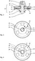
- the annular surface 28 of the drive-side disk 25 is in Fig. 3 shown in a plan view.
- the annular surface 28 has an inner radius 31 and an outer radius 32.
- the exemplary annular surface 28 has three first sectors 33 which are provided with a rubber coating.
- the first sectors 33 preferably each cover an angle of less than 45 degrees viewed from the axis of rotation 23 .
- the three first sectors 33 are distributed symmetrically about the axis of rotation 23 .
- the remaining other three second sectors 34 are polished steel surfaces.
- the annular surface 29 of the driven-side disk 26 is preferably formed equal to the annular surface 33 of the drive-side disk 25 .
- the driven-side annular surface 29 also has three (third) sectors 35 which are rubberized. Their dimensions are preferably equal to the first sectors 33.
- the remaining (fourth) sectors 36 are polished steel surfaces.
- the slip clutch 24 remains in engagement as long as the rubberized first and third sectors 33, 35 lie on each other.
- the contact pressure of the spring 30 increases the adhesion of the two sectors 33 , 35.
- the driving pulley 25 slips and the first sectors 33 increasingly and finally overlap exclusively with the fourth sectors 36.
- the driving pulley 25 can now be rotated with almost no torque against the abortive disk 26 . Accordingly, the motor 5 accelerates .
- the large angle of preferably more than 75 degrees between the first sectors 33 allows a long acceleration phase.
- the motor 5 can generate a high torque peak, for example, to release a drill 4 , which can not turn at a lower static torque and the slip clutch 24 triggers.
- the annular surfaces 28, 29 have three, two or preferably only a first w. third sector 33, 35.
- the sectors 33, 35 occupy between 25% and 40% of the annular surface 29 in order to provide sufficient adhesion for the transmission of torque.
- Fig. 4 shows a further embodiment in which the driving pulley 25 has two concentric annular surfaces 28, 37 . The two annular surfaces 28, 37 do not overlap.
- Both annular surfaces 28, 37 have first sectors 33, 38 with a rubber coating and second sectors 34, 39 with a polished steel surface.
- the first sectors 33 of the outer annular surface 28 are preferably offset from the sectors 38 of the inner annular surface 37 by half the angle between the first sectors 33 of the outer annular surface 28 .
- Fig. 5 and Fig. 6 show a further embodiment in which the second sectors 34 include one or more to the axis 23 concentric circular webs 40 .
- the roof surfaces of the webs 40 lie in a plane with the annular surface 28. Between the webs 40 is a corresponding concentric groove.
- the first sectors 33 touch completely and the second sectors touch only by means of the webs 40, the annular surface 29 of the driven pulley 26.
- the driven pulley 26 may be formed identical to the driving pulley 25 .
Landscapes
- Engineering & Computer Science (AREA)
- General Engineering & Computer Science (AREA)
- Mechanical Engineering (AREA)
- Percussive Tools And Related Accessories (AREA)
Claims (5)
- Machine-outil manuelle (1) comportant :un mandrin (2) pour recevoir un outil (4) sur un axe de travail (11),un moteur (5),un mécanisme de percussion pneumatique (6),un arbre entraîné (7) qui est couplé au mandrin (2) pour entraîner l'outil en rotation autour de l'axe de travail (11) etun accouplement à friction (24) qui est agencé dans la transmission entre le moteur (5) et l'arbre entraîné (7),dans laquelle l'accouplement à friction (24) comporte un disque côté moteur (25) et un disque côté entraîné (26),caractérisée en ce que le disque côté moteur (25) sur une surface motrice annulaire (28) adjacente au disque côté entraîné (26) comporte des premiers secteurs (33) avec une valeur de friction élevée et des deuxièmes secteurs (34) avec une valeur de friction faible, et le disque côté entraîné (26) sur la surface motrice annulaire (29) adjacente à la surface motrice annulaire (28) comporte des troisièmes secteurs (35) avec une valeur de friction élevée et des quatrièmes secteurs (36) avec une valeur de friction faible, et en ce queles premiers secteurs (33) et les troisièmes secteurs (35) comportent une surface caoutchoutée et les deuxièmes secteurs (34) et les quatrièmes secteurs (36) comportent une surface en acier polie.
- Machine-outil manuelle (1) selon la revendication 1, caractérisée en ce qu'un ressort (30) maintient les deux surfaces annulaires (28, 29) en contact permanent.
- Machine-outil manuelle (1) selon l'une des revendications précédentes, caractérisée en ce que les surfaces annulaires (28, 29) comportent respectivement au maximum trois premiers secteurs (33) et au maximum trois troisièmes secteurs (35).
- Machine-outil manuelle (1) selon la revendication 3, caractérisée en ce que les premiers secteurs (33) et les troisièmes secteurs (35) recouvrent un quart à un tiers des surfaces annulaires (28, 29).
- Machine-outil manuelle (1) selon l'une des revendications précédentes, caractérisée en ce que les deuxièmes secteurs (34) jusqu'à l'axe de travail (11) comporte des nervures concentriques (40) qui se situent dans un plan avec le premier secteur (33).
Applications Claiming Priority (2)
| Application Number | Priority Date | Filing Date | Title |
|---|---|---|---|
| EP14165357.6A EP2937186A1 (fr) | 2014-04-22 | 2014-04-22 | Machine-outil portative |
| PCT/EP2015/057158 WO2015161994A1 (fr) | 2014-04-22 | 2015-04-01 | Machine-outil à main |
Publications (2)
| Publication Number | Publication Date |
|---|---|
| EP3134229A1 EP3134229A1 (fr) | 2017-03-01 |
| EP3134229B1 true EP3134229B1 (fr) | 2018-10-24 |
Family
ID=50513759
Family Applications (2)
| Application Number | Title | Priority Date | Filing Date |
|---|---|---|---|
| EP14165357.6A Withdrawn EP2937186A1 (fr) | 2014-04-22 | 2014-04-22 | Machine-outil portative |
| EP15714205.0A Active EP3134229B1 (fr) | 2014-04-22 | 2015-04-01 | Machine-outil portative |
Family Applications Before (1)
| Application Number | Title | Priority Date | Filing Date |
|---|---|---|---|
| EP14165357.6A Withdrawn EP2937186A1 (fr) | 2014-04-22 | 2014-04-22 | Machine-outil portative |
Country Status (3)
| Country | Link |
|---|---|
| US (1) | US20170043465A1 (fr) |
| EP (2) | EP2937186A1 (fr) |
| WO (1) | WO2015161994A1 (fr) |
Families Citing this family (2)
| Publication number | Priority date | Publication date | Assignee | Title |
|---|---|---|---|---|
| US11529727B2 (en) | 2019-10-21 | 2022-12-20 | Makita Corporation | Power tool having hammer mechanism |
| JP7618477B2 (ja) | 2021-03-29 | 2025-01-21 | 日本プラスト株式会社 | 連結装置 |
Family Cites Families (4)
| Publication number | Priority date | Publication date | Assignee | Title |
|---|---|---|---|---|
| SU947416A1 (ru) * | 1978-12-27 | 1982-07-30 | Всесоюзный Научно-Исследовательский И Проектно-Конструкторский Институт Механизированного И Ручного Строительно-Монтажного Инструмента,Вибраторов И Строительно-Отделочных Машин | Машина ударно-вращательного действи |
| JPS5969529A (ja) * | 1982-10-13 | 1984-04-19 | Fuji Xerox Co Ltd | 乾式スリツプクラツチ |
| DE3942806A1 (de) * | 1989-12-23 | 1991-06-27 | Metabowerke Kg | Rutschkupplung zur begrenzung des maximalen drehmoments eines elektrowerkzeugs |
| DE19646381A1 (de) | 1996-11-11 | 1998-05-14 | Hilti Ag | Handgerät |
-
2014
- 2014-04-22 EP EP14165357.6A patent/EP2937186A1/fr not_active Withdrawn
-
2015
- 2015-04-01 EP EP15714205.0A patent/EP3134229B1/fr active Active
- 2015-04-01 WO PCT/EP2015/057158 patent/WO2015161994A1/fr not_active Ceased
- 2015-04-01 US US15/305,978 patent/US20170043465A1/en not_active Abandoned
Non-Patent Citations (1)
| Title |
|---|
| None * |
Also Published As
| Publication number | Publication date |
|---|---|
| EP2937186A1 (fr) | 2015-10-28 |
| WO2015161994A1 (fr) | 2015-10-29 |
| EP3134229A1 (fr) | 2017-03-01 |
| US20170043465A1 (en) | 2017-02-16 |
Similar Documents
| Publication | Publication Date | Title |
|---|---|---|
| DE102008022454B4 (de) | Bohrhammer | |
| EP2379281B1 (fr) | Machine-outil portative | |
| DE2242944B2 (de) | Bohrhammer | |
| DE102011084499A1 (de) | Werkzeugvorsatz | |
| DE2252951B2 (de) | Bohrhammer | |
| EP1862265A3 (fr) | Machine-outil manuelle dotée d'un dispositif d'accouplement à patinage | |
| DE202008001449U1 (de) | Schalteinrichtung für Schlagwerkzeug | |
| DE102012209874A1 (de) | Getriebevorrichtung | |
| WO2016119988A1 (fr) | Dispositif à percussion, en particulier pour clé à chocs | |
| DE2147383C2 (de) | Schlagschraubmaschine, insbesondere für Schienenbefestigungschrauben | |
| EP2612731B1 (fr) | Dispositif d'outil manuel | |
| EP3053708B1 (fr) | Dispositif auxiliaire | |
| EP2134512B1 (fr) | Système d'engrenage | |
| EP3134229B1 (fr) | Machine-outil portative | |
| WO2018024475A1 (fr) | Dispositif adaptateur | |
| EP2561962B1 (fr) | Machine-outil manuelle | |
| DE102007062248A1 (de) | Handwerkzeugmaschine mit einer, mindestens eine drehbar gelagerte Zwischenwelle umfassenden Getriebevorrichtung | |
| EP2700477B1 (fr) | Agencement d'engrenage pour une machine-outil et machine-outil | |
| EP3456479B1 (fr) | Dispositif d'entraînement pour une machine-outil motorisée | |
| WO2009092366A2 (fr) | Mécanisme de percussion pour une machine-outil, notamment pour une machine-outil manuelle telle qu'un marteau perforateur électrique ou une visseuse à percussion | |
| DE102014101827A1 (de) | Bohrmaschine und Bohrwerkzeug hierfür | |
| EP2522466B1 (fr) | Machine-outil portative et méthode d'opération d'une machine-outil portative | |
| EP2104594B1 (fr) | Machine-outil portative | |
| EP3782766A1 (fr) | Machine-outil manuelle | |
| DE102008008815A1 (de) | Werkzeugmaschine, Verfahren zur Montage einer Werkzeugmaschine |
Legal Events
| Date | Code | Title | Description |
|---|---|---|---|
| STAA | Information on the status of an ep patent application or granted ep patent |
Free format text: STATUS: THE INTERNATIONAL PUBLICATION HAS BEEN MADE |
|
| PUAI | Public reference made under article 153(3) epc to a published international application that has entered the european phase |
Free format text: ORIGINAL CODE: 0009012 |
|
| STAA | Information on the status of an ep patent application or granted ep patent |
Free format text: STATUS: REQUEST FOR EXAMINATION WAS MADE |
|
| 17P | Request for examination filed |
Effective date: 20161122 |
|
| AK | Designated contracting states |
Kind code of ref document: A1 Designated state(s): AL AT BE BG CH CY CZ DE DK EE ES FI FR GB GR HR HU IE IS IT LI LT LU LV MC MK MT NL NO PL PT RO RS SE SI SK SM TR |
|
| AX | Request for extension of the european patent |
Extension state: BA ME |
|
| DAV | Request for validation of the european patent (deleted) | ||
| DAX | Request for extension of the european patent (deleted) | ||
| GRAP | Despatch of communication of intention to grant a patent |
Free format text: ORIGINAL CODE: EPIDOSNIGR1 |
|
| STAA | Information on the status of an ep patent application or granted ep patent |
Free format text: STATUS: GRANT OF PATENT IS INTENDED |
|
| RIC1 | Information provided on ipc code assigned before grant |
Ipc: F16D 7/02 20060101ALI20180627BHEP Ipc: B25D 16/00 20060101AFI20180627BHEP |
|
| INTG | Intention to grant announced |
Effective date: 20180726 |
|
| GRAS | Grant fee paid |
Free format text: ORIGINAL CODE: EPIDOSNIGR3 |
|
| GRAA | (expected) grant |
Free format text: ORIGINAL CODE: 0009210 |
|
| STAA | Information on the status of an ep patent application or granted ep patent |
Free format text: STATUS: THE PATENT HAS BEEN GRANTED |
|
| AK | Designated contracting states |
Kind code of ref document: B1 Designated state(s): AL AT BE BG CH CY CZ DE DK EE ES FI FR GB GR HR HU IE IS IT LI LT LU LV MC MK MT NL NO PL PT RO RS SE SI SK SM TR |
|
| REG | Reference to a national code |
Ref country code: CH Ref legal event code: EP |
|
| REG | Reference to a national code |
Ref country code: IE Ref legal event code: FG4D Free format text: LANGUAGE OF EP DOCUMENT: GERMAN |
|
| REG | Reference to a national code |
Ref country code: AT Ref legal event code: REF Ref document number: 1056121 Country of ref document: AT Kind code of ref document: T Effective date: 20181115 |
|
| REG | Reference to a national code |
Ref country code: DE Ref legal event code: R096 Ref document number: 502015006570 Country of ref document: DE |
|
| REG | Reference to a national code |
Ref country code: NL Ref legal event code: MP Effective date: 20181024 |
|
| REG | Reference to a national code |
Ref country code: LT Ref legal event code: MG4D |
|
| PG25 | Lapsed in a contracting state [announced via postgrant information from national office to epo] |
Ref country code: NL Free format text: LAPSE BECAUSE OF FAILURE TO SUBMIT A TRANSLATION OF THE DESCRIPTION OR TO PAY THE FEE WITHIN THE PRESCRIBED TIME-LIMIT Effective date: 20181024 |
|
| PG25 | Lapsed in a contracting state [announced via postgrant information from national office to epo] |
Ref country code: LV Free format text: LAPSE BECAUSE OF FAILURE TO SUBMIT A TRANSLATION OF THE DESCRIPTION OR TO PAY THE FEE WITHIN THE PRESCRIBED TIME-LIMIT Effective date: 20181024 Ref country code: PL Free format text: LAPSE BECAUSE OF FAILURE TO SUBMIT A TRANSLATION OF THE DESCRIPTION OR TO PAY THE FEE WITHIN THE PRESCRIBED TIME-LIMIT Effective date: 20181024 Ref country code: HR Free format text: LAPSE BECAUSE OF FAILURE TO SUBMIT A TRANSLATION OF THE DESCRIPTION OR TO PAY THE FEE WITHIN THE PRESCRIBED TIME-LIMIT Effective date: 20181024 Ref country code: FI Free format text: LAPSE BECAUSE OF FAILURE TO SUBMIT A TRANSLATION OF THE DESCRIPTION OR TO PAY THE FEE WITHIN THE PRESCRIBED TIME-LIMIT Effective date: 20181024 Ref country code: NO Free format text: LAPSE BECAUSE OF FAILURE TO SUBMIT A TRANSLATION OF THE DESCRIPTION OR TO PAY THE FEE WITHIN THE PRESCRIBED TIME-LIMIT Effective date: 20190124 Ref country code: IS Free format text: LAPSE BECAUSE OF FAILURE TO SUBMIT A TRANSLATION OF THE DESCRIPTION OR TO PAY THE FEE WITHIN THE PRESCRIBED TIME-LIMIT Effective date: 20190224 Ref country code: BG Free format text: LAPSE BECAUSE OF FAILURE TO SUBMIT A TRANSLATION OF THE DESCRIPTION OR TO PAY THE FEE WITHIN THE PRESCRIBED TIME-LIMIT Effective date: 20190124 Ref country code: ES Free format text: LAPSE BECAUSE OF FAILURE TO SUBMIT A TRANSLATION OF THE DESCRIPTION OR TO PAY THE FEE WITHIN THE PRESCRIBED TIME-LIMIT Effective date: 20181024 Ref country code: LT Free format text: LAPSE BECAUSE OF FAILURE TO SUBMIT A TRANSLATION OF THE DESCRIPTION OR TO PAY THE FEE WITHIN THE PRESCRIBED TIME-LIMIT Effective date: 20181024 |
|
| PG25 | Lapsed in a contracting state [announced via postgrant information from national office to epo] |
Ref country code: GR Free format text: LAPSE BECAUSE OF FAILURE TO SUBMIT A TRANSLATION OF THE DESCRIPTION OR TO PAY THE FEE WITHIN THE PRESCRIBED TIME-LIMIT Effective date: 20190125 Ref country code: AL Free format text: LAPSE BECAUSE OF FAILURE TO SUBMIT A TRANSLATION OF THE DESCRIPTION OR TO PAY THE FEE WITHIN THE PRESCRIBED TIME-LIMIT Effective date: 20181024 Ref country code: PT Free format text: LAPSE BECAUSE OF FAILURE TO SUBMIT A TRANSLATION OF THE DESCRIPTION OR TO PAY THE FEE WITHIN THE PRESCRIBED TIME-LIMIT Effective date: 20190224 Ref country code: SE Free format text: LAPSE BECAUSE OF FAILURE TO SUBMIT A TRANSLATION OF THE DESCRIPTION OR TO PAY THE FEE WITHIN THE PRESCRIBED TIME-LIMIT Effective date: 20181024 Ref country code: RS Free format text: LAPSE BECAUSE OF FAILURE TO SUBMIT A TRANSLATION OF THE DESCRIPTION OR TO PAY THE FEE WITHIN THE PRESCRIBED TIME-LIMIT Effective date: 20181024 |
|
| REG | Reference to a national code |
Ref country code: DE Ref legal event code: R097 Ref document number: 502015006570 Country of ref document: DE |
|
| PG25 | Lapsed in a contracting state [announced via postgrant information from national office to epo] |
Ref country code: DK Free format text: LAPSE BECAUSE OF FAILURE TO SUBMIT A TRANSLATION OF THE DESCRIPTION OR TO PAY THE FEE WITHIN THE PRESCRIBED TIME-LIMIT Effective date: 20181024 Ref country code: CZ Free format text: LAPSE BECAUSE OF FAILURE TO SUBMIT A TRANSLATION OF THE DESCRIPTION OR TO PAY THE FEE WITHIN THE PRESCRIBED TIME-LIMIT Effective date: 20181024 Ref country code: IT Free format text: LAPSE BECAUSE OF FAILURE TO SUBMIT A TRANSLATION OF THE DESCRIPTION OR TO PAY THE FEE WITHIN THE PRESCRIBED TIME-LIMIT Effective date: 20181024 |
|
| PG25 | Lapsed in a contracting state [announced via postgrant information from national office to epo] |
Ref country code: RO Free format text: LAPSE BECAUSE OF FAILURE TO SUBMIT A TRANSLATION OF THE DESCRIPTION OR TO PAY THE FEE WITHIN THE PRESCRIBED TIME-LIMIT Effective date: 20181024 Ref country code: SK Free format text: LAPSE BECAUSE OF FAILURE TO SUBMIT A TRANSLATION OF THE DESCRIPTION OR TO PAY THE FEE WITHIN THE PRESCRIBED TIME-LIMIT Effective date: 20181024 Ref country code: EE Free format text: LAPSE BECAUSE OF FAILURE TO SUBMIT A TRANSLATION OF THE DESCRIPTION OR TO PAY THE FEE WITHIN THE PRESCRIBED TIME-LIMIT Effective date: 20181024 Ref country code: SM Free format text: LAPSE BECAUSE OF FAILURE TO SUBMIT A TRANSLATION OF THE DESCRIPTION OR TO PAY THE FEE WITHIN THE PRESCRIBED TIME-LIMIT Effective date: 20181024 |
|
| PLBE | No opposition filed within time limit |
Free format text: ORIGINAL CODE: 0009261 |
|
| STAA | Information on the status of an ep patent application or granted ep patent |
Free format text: STATUS: NO OPPOSITION FILED WITHIN TIME LIMIT |
|
| 26N | No opposition filed |
Effective date: 20190725 |
|
| PG25 | Lapsed in a contracting state [announced via postgrant information from national office to epo] |
Ref country code: SI Free format text: LAPSE BECAUSE OF FAILURE TO SUBMIT A TRANSLATION OF THE DESCRIPTION OR TO PAY THE FEE WITHIN THE PRESCRIBED TIME-LIMIT Effective date: 20181024 |
|
| REG | Reference to a national code |
Ref country code: CH Ref legal event code: PL |
|
| REG | Reference to a national code |
Ref country code: BE Ref legal event code: MM Effective date: 20190430 |
|
| GBPC | Gb: european patent ceased through non-payment of renewal fee |
Effective date: 20190401 |
|
| PG25 | Lapsed in a contracting state [announced via postgrant information from national office to epo] |
Ref country code: MC Free format text: LAPSE BECAUSE OF FAILURE TO SUBMIT A TRANSLATION OF THE DESCRIPTION OR TO PAY THE FEE WITHIN THE PRESCRIBED TIME-LIMIT Effective date: 20181024 Ref country code: LU Free format text: LAPSE BECAUSE OF NON-PAYMENT OF DUE FEES Effective date: 20190401 |
|
| PG25 | Lapsed in a contracting state [announced via postgrant information from national office to epo] |
Ref country code: LI Free format text: LAPSE BECAUSE OF NON-PAYMENT OF DUE FEES Effective date: 20190430 Ref country code: CH Free format text: LAPSE BECAUSE OF NON-PAYMENT OF DUE FEES Effective date: 20190430 Ref country code: GB Free format text: LAPSE BECAUSE OF NON-PAYMENT OF DUE FEES Effective date: 20190401 |
|
| PG25 | Lapsed in a contracting state [announced via postgrant information from national office to epo] |
Ref country code: BE Free format text: LAPSE BECAUSE OF NON-PAYMENT OF DUE FEES Effective date: 20190430 Ref country code: FR Free format text: LAPSE BECAUSE OF NON-PAYMENT OF DUE FEES Effective date: 20190430 |
|
| PG25 | Lapsed in a contracting state [announced via postgrant information from national office to epo] |
Ref country code: TR Free format text: LAPSE BECAUSE OF FAILURE TO SUBMIT A TRANSLATION OF THE DESCRIPTION OR TO PAY THE FEE WITHIN THE PRESCRIBED TIME-LIMIT Effective date: 20181024 |
|
| PG25 | Lapsed in a contracting state [announced via postgrant information from national office to epo] |
Ref country code: IE Free format text: LAPSE BECAUSE OF NON-PAYMENT OF DUE FEES Effective date: 20190401 |
|
| PG25 | Lapsed in a contracting state [announced via postgrant information from national office to epo] |
Ref country code: CY Free format text: LAPSE BECAUSE OF FAILURE TO SUBMIT A TRANSLATION OF THE DESCRIPTION OR TO PAY THE FEE WITHIN THE PRESCRIBED TIME-LIMIT Effective date: 20181024 |
|
| REG | Reference to a national code |
Ref country code: AT Ref legal event code: MM01 Ref document number: 1056121 Country of ref document: AT Kind code of ref document: T Effective date: 20200401 |
|
| PG25 | Lapsed in a contracting state [announced via postgrant information from national office to epo] |
Ref country code: HU Free format text: LAPSE BECAUSE OF FAILURE TO SUBMIT A TRANSLATION OF THE DESCRIPTION OR TO PAY THE FEE WITHIN THE PRESCRIBED TIME-LIMIT; INVALID AB INITIO Effective date: 20150401 Ref country code: MT Free format text: LAPSE BECAUSE OF FAILURE TO SUBMIT A TRANSLATION OF THE DESCRIPTION OR TO PAY THE FEE WITHIN THE PRESCRIBED TIME-LIMIT Effective date: 20181024 |
|
| PG25 | Lapsed in a contracting state [announced via postgrant information from national office to epo] |
Ref country code: AT Free format text: LAPSE BECAUSE OF NON-PAYMENT OF DUE FEES Effective date: 20200401 |
|
| PG25 | Lapsed in a contracting state [announced via postgrant information from national office to epo] |
Ref country code: MK Free format text: LAPSE BECAUSE OF FAILURE TO SUBMIT A TRANSLATION OF THE DESCRIPTION OR TO PAY THE FEE WITHIN THE PRESCRIBED TIME-LIMIT Effective date: 20181024 |
|
| PGFP | Annual fee paid to national office [announced via postgrant information from national office to epo] |
Ref country code: DE Payment date: 20250422 Year of fee payment: 11 |