EP3134757B1 - Système de ciblage - Google Patents
Système de ciblage Download PDFInfo
- Publication number
- EP3134757B1 EP3134757B1 EP15719940.7A EP15719940A EP3134757B1 EP 3134757 B1 EP3134757 B1 EP 3134757B1 EP 15719940 A EP15719940 A EP 15719940A EP 3134757 B1 EP3134757 B1 EP 3134757B1
- Authority
- EP
- European Patent Office
- Prior art keywords
- channel
- fiber
- measurement
- sample
- channels
- Prior art date
- Legal status (The legal status is an assumption and is not a legal conclusion. Google has not performed a legal analysis and makes no representation as to the accuracy of the status listed.)
- Active
Links
Images

Classifications
-
- G—PHYSICS
- G01—MEASURING; TESTING
- G01N—INVESTIGATING OR ANALYSING MATERIALS BY DETERMINING THEIR CHEMICAL OR PHYSICAL PROPERTIES
- G01N21/00—Investigating or analysing materials by the use of optical means, i.e. using sub-millimetre waves, infrared, visible or ultraviolet light
- G01N21/01—Arrangements or apparatus for facilitating the optical investigation
-
- G—PHYSICS
- G01—MEASURING; TESTING
- G01J—MEASUREMENT OF INTENSITY, VELOCITY, SPECTRAL CONTENT, POLARISATION, PHASE OR PULSE CHARACTERISTICS OF INFRARED, VISIBLE OR ULTRAVIOLET LIGHT; COLORIMETRY; RADIATION PYROMETRY
- G01J3/00—Spectrometry; Spectrophotometry; Monochromators; Measuring colours
- G01J3/02—Details
- G01J3/0289—Field-of-view determination; Aiming or pointing of a spectrometer; Adjusting alignment; Encoding angular position; Size of measurement area; Position tracking
-
- G—PHYSICS
- G01—MEASURING; TESTING
- G01J—MEASUREMENT OF INTENSITY, VELOCITY, SPECTRAL CONTENT, POLARISATION, PHASE OR PULSE CHARACTERISTICS OF INFRARED, VISIBLE OR ULTRAVIOLET LIGHT; COLORIMETRY; RADIATION PYROMETRY
- G01J1/00—Photometry, e.g. photographic exposure meter
- G01J1/02—Details
- G01J1/04—Optical or mechanical part supplementary adjustable parts
- G01J1/0407—Optical elements not provided otherwise, e.g. manifolds, windows, holograms, gratings
- G01J1/0425—Optical elements not provided otherwise, e.g. manifolds, windows, holograms, gratings using optical fibers
-
- G—PHYSICS
- G01—MEASURING; TESTING
- G01J—MEASUREMENT OF INTENSITY, VELOCITY, SPECTRAL CONTENT, POLARISATION, PHASE OR PULSE CHARACTERISTICS OF INFRARED, VISIBLE OR ULTRAVIOLET LIGHT; COLORIMETRY; RADIATION PYROMETRY
- G01J1/00—Photometry, e.g. photographic exposure meter
- G01J1/02—Details
- G01J1/04—Optical or mechanical part supplementary adjustable parts
- G01J1/0407—Optical elements not provided otherwise, e.g. manifolds, windows, holograms, gratings
- G01J1/0462—Slit arrangements
-
- G—PHYSICS
- G01—MEASURING; TESTING
- G01J—MEASUREMENT OF INTENSITY, VELOCITY, SPECTRAL CONTENT, POLARISATION, PHASE OR PULSE CHARACTERISTICS OF INFRARED, VISIBLE OR ULTRAVIOLET LIGHT; COLORIMETRY; RADIATION PYROMETRY
- G01J3/00—Spectrometry; Spectrophotometry; Monochromators; Measuring colours
- G01J3/02—Details
-
- G—PHYSICS
- G01—MEASURING; TESTING
- G01J—MEASUREMENT OF INTENSITY, VELOCITY, SPECTRAL CONTENT, POLARISATION, PHASE OR PULSE CHARACTERISTICS OF INFRARED, VISIBLE OR ULTRAVIOLET LIGHT; COLORIMETRY; RADIATION PYROMETRY
- G01J3/00—Spectrometry; Spectrophotometry; Monochromators; Measuring colours
- G01J3/02—Details
- G01J3/0205—Optical elements not provided otherwise, e.g. optical manifolds, diffusers, windows
- G01J3/021—Optical elements not provided otherwise, e.g. optical manifolds, diffusers, windows using plane or convex mirrors, parallel phase plates, or particular reflectors
-
- G—PHYSICS
- G01—MEASURING; TESTING
- G01J—MEASUREMENT OF INTENSITY, VELOCITY, SPECTRAL CONTENT, POLARISATION, PHASE OR PULSE CHARACTERISTICS OF INFRARED, VISIBLE OR ULTRAVIOLET LIGHT; COLORIMETRY; RADIATION PYROMETRY
- G01J3/00—Spectrometry; Spectrophotometry; Monochromators; Measuring colours
- G01J3/02—Details
- G01J3/0205—Optical elements not provided otherwise, e.g. optical manifolds, diffusers, windows
- G01J3/0218—Optical elements not provided otherwise, e.g. optical manifolds, diffusers, windows using optical fibers
-
- G—PHYSICS
- G01—MEASURING; TESTING
- G01J—MEASUREMENT OF INTENSITY, VELOCITY, SPECTRAL CONTENT, POLARISATION, PHASE OR PULSE CHARACTERISTICS OF INFRARED, VISIBLE OR ULTRAVIOLET LIGHT; COLORIMETRY; RADIATION PYROMETRY
- G01J3/00—Spectrometry; Spectrophotometry; Monochromators; Measuring colours
- G01J3/02—Details
- G01J3/04—Slit arrangements slit adjustment
-
- G—PHYSICS
- G02—OPTICS
- G02B—OPTICAL ELEMENTS, SYSTEMS OR APPARATUS
- G02B6/00—Light guides; Structural details of arrangements comprising light guides and other optical elements, e.g. couplings
- G02B6/24—Coupling light guides
- G02B6/42—Coupling light guides with opto-electronic elements
Definitions
- the present disclosure relates to a targeting system for a spectrophotometer.
- Spectrophotometers are commonly used for measuring color samples.
- U.S. Pat. No. 7,773,221B2 the "'221 Patent”
- the '221 Patent discloses a color measurement device for use at various stages of industrial processes.
- the device of the '221 Patent offers enhanced insensitivity to ambient light, measurement depth variations, and/or ambient temperature variations.
- the device of the '221 Patent may be embodied as an LED- based color measurement spectrophotometer.
- One issue that arises in testing samples with a spectrophotometer is the need to verify that the proper region of interest (ROI) of a sample is being measured.
- ROI region of interest
- a sample may have different portions with different colors, and a particular ROI may be desired to be measured by a user. It would be desirable for a user to have an easy way to determine the precise location of the sample to be measured.
- GB 2 479 012 A discloses devices and methods for aligning a collection fibre with a sampling region in particular for a Raman-scattering measurement system.
- An illumination source projects an illumination signal onto a sample space.
- a collection fibre receives a signal emitted from the sample space.
- An alignment fibre projects an alignment signal onto the sample space.
- the ends of the alignment and collection fibres are positioned in a known configuration.
- the collection fibre may be a central optical fibre within an optical fibre bundle surrounded by six alignment fibres.
- a camera detects the position of the projected alignment and illumination signals in the sample space.
- An adjuster adjusts the position of at least one of the projected illumination or alignment signal so that the signals can be positioned with a selected configuration in the sample space.
- the ends of the collection fibre and illumination fibre may be positioned adjacent one another with a known offset for example positioned concentrically within a fibre bundle.
- the present disclosure provides a targeting system for a spectrophotometer.
- the targeting system uses a light source to illuminate a sample at the same location that the spectrometer measures the properties of the sample (the specific ROI). Light is projected onto the sample plane with the pickup optics, precisely defining the area that is measured with the instrument. Thus, a user can ensure that the spectrometer is taking measurements at the desired location on a sample.
- the targeting system for a spectrophotometer includes a plurality of fiber channels, including at least one measurement channel and at least one illumination channel.
- a slit assembly includes a translucent layer disposed adjacent the plurality of fiber channels, and reflective portion disposed adjacent the translucent layer. Each fiber channel includes a first end, the first end offset from the reflective portion of the slit assembly to allow light transfer from one fiber channel to an adjacent fiber channel.
- a light source is in optical communication with at least one illumination channel.
- a sample plane is in optical communication with a second end of the measurement channel. The system is configured such that light is transmitted from the light source, through the at least one illumination channel, reflected off the slit assembly, transmitted through the measurement channel, and onto the sample plane.
- a method of targeting a sample for a spectrophotometer includes providing a plurality of fiber channels, including at least one measurement channel and at least one illumination channel.
- a slit assembly includes a translucent layer disposed adjacent the plurality of fiber channels and reflective portion disposed adjacent the translucent layer. Each fiber channel includes a first end offset from the reflective portion of the slit assembly to allow light transfer from one fiber channel to an adjacent fiber channel.
- a light source is in optical communication with the at least one illumination channel.
- a sample is in a sample plane in optical communication with a second end of the measurement channel.
- a targeting step light is transmitted from the light source, through the at least one illumination channel, reflected off the slit assembly, transmitted through the measurement channel, and onto the sample plane, such that the sample plane is illuminated in at the ROI.
- a measurement step light is transmitted from a second light source, onto the sample, and through the at least one measurement channel to a spectrophotometer, wherein the first light source illuminates the sample in a same location where measurements are taken by the spectrophotometer.
- the present disclosure provides a targeting system for a spectrophotometer.
- the targeting system uses a light source to illuminate a sample at the same location that the spectrometer measures the properties of the sample. Light is projected onto the sample plane with the pickup optics, precisely defining the area that is measured with the instrument. Thus, a user can ensure that the spectrometer is taking measurements at the desired location on a sample.
- FIG. 1 is a schematic view of an embodiment of a targeting system 1 for a spectrophotometer 9 in a targeting mode.
- FIG. 2 shows the same system in a measurement mode.
- the system 1 includes a plurality of fiber channels 3, 4.
- the fiber channels may be any optical fiber suitable for conveying light.
- the fiber channels include at least one illumination channel 3 and at least one measurement channel 4.
- the illumination channel 3 extends from illumination source 11 to slit assembly 8.
- the measurement channel 4 extends from slit assembly 8, through ferrule 22, through measurement optics 5, to sample 6.
- the ferrules 12 and 22 are disposed at the ends of the respective fiber channels and serve to hold them in place.
- measurement channel 4 serves as an illumination channel during targeting mode and a measurement channel during measurement mode. Because of this, the same location on the sample that is illuminated during targeting mode is measured during measurement mode.
- light source 11 is in optical communication with the illumination channel 3.
- Light source 11 may be a green laser light (532nm) from a laser diode. Of course, other light sources are possible.
- the sample plane 6 is in optical communication with a second end of the measurement channel 4. The system is configured such that light is transmitted from the light source 11, through the illumination channel 3, reflected off the slit assembly 8, transmitted through the measurement channel 4, and onto the sample plane 6.
- the spectrophotometer 9 is in optical communication with the measurement channel 4.
- the sample plane 6 is illuminated in the same location where measurements are taken by the spectrophotometer 9.
- the spot size of the sample plane preferably ranges from 2.5 mm to 20 mm, 5 mm to 15 mm, or 7 mm to 12 mm.
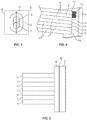
- FIG. 3 is a cross sectional view of the interface between the ends of the fiber channel and the optical slit assembly 8.
- the slit assembly 8 includes a mirror coating 10 and a slit 11.
- the slit assembly 8 processes the light entering the spectrophotometer 9.
- the mirror coating 10 acts to reflect light from the illumination channel 3 into the adjacent measurement channel 4.
- the measurement channels 4 may include at least one reference channel, a specular included channel, and a specular excluded channel. Specular included reflectance and specular excluded reflectance are terms known in the art.
- the specular included reflectance also known as the "total reflectance” includes both the diffuse and specular components.
- the specular excluded reflectance also known as the "diffuse reflectance” includes only the diffuse component; the specular component is completely excluded.
- the diameter of the optical fiber is generally between 200 um and 1 mm, preferably between 400 and 600 um, most preferably around 500 um.
- FIG. 4 is a perspective illustration of the interface between the ends of the fiber channels and the optical slit assembly 8.
- Each fiber channel includes an end offset from the reflective portion of the slit assembly to allow light transfer from one fiber channel to an adjacent fiber channel.
- Illumination channel fibers 3 include ends 13 offset from mirror portion 10 of the optical slit assembly 8.
- Measurement channel fibers 4 include ends 14 offset from mirror portion 10 of the optical slit assembly 8.
- a translucent layer 16 is disposed adjacent the ends of the plurality of fiber channels, and a reflective portion 10 is disposed adjacent the translucent or clear layer 16, opposite the ends of the fiber channels.
- the ends of the fiber channels may either be offset from the clear layer of the slit assembly 8, or touching it, as long as the ends of the channel are offset from the reflective layer 10.
- a small air gap may be present between ends of the channels and the translucent layer 16 of the slit assembly 8.
- Another possibility is to use an index matching optical gel or cement and have the fibers essentially in contact with the translucent layer 16 of the slit assembly 8.
- a third option is not to have any clear layer, and simply create a gap that allows light to reflect from the reflective slit 10 and back into appropriate the measurement fiber.
- the translucent layer 16 serves several purposes: 1) if it is in contact with the ends of the fibers, it ensures a consistent gap between the ends of the fibers and the reflective slit 11, and 2) the translucent layer 16 protects the reflective layer 10 from oxidation or dulling of the high reflectance coating.
- the displacement of the slit assembly 8 from the end of the fiber channels is preferably between 0.5 mm and 1.2 mm, preferably around 0.8 mm.
- light is transmitted from each illumination channel 3 to the adjacent illumination measurement channel(s) 4.
- the offset of the reflective portion 10 from the ends of the channels allows optical spread to enable this light transfer.
- the present system provides a targeting system for a spectrophotometer that easily allows a user to select the precise location of a sample that is desired to be measured.
- the system uses the same optical fiber channels for both targeting and measurement, thus allowing precise sample area selection.
Landscapes
- Physics & Mathematics (AREA)
- Spectroscopy & Molecular Physics (AREA)
- General Physics & Mathematics (AREA)
- Optics & Photonics (AREA)
- Analytical Chemistry (AREA)
- Chemical & Material Sciences (AREA)
- Life Sciences & Earth Sciences (AREA)
- Biochemistry (AREA)
- General Health & Medical Sciences (AREA)
- Immunology (AREA)
- Pathology (AREA)
- Health & Medical Sciences (AREA)
- Investigating Or Analysing Materials By Optical Means (AREA)
Claims (15)
- Système de ciblage (1) pour un spectrophotomètre, comprenant:une pluralité de canaux de fibre (3, 4), comprenant :au moins un canal de mesure (4) ; etau moins un canal d'éclairage (3) ;un ensemble fente (8) comprenant :une couche translucide (16) disposée de manière adjacente à la pluralité de canaux de fibre (3, 4), etune partie réfléchissante (10) disposée de manière adjacente à la couche translucide (16);dans lequel chaque canal de fibre (3, 4) comprend une première extrémité, la première extrémité étant décalée de la partie réfléchissante (10) de l'ensemble fente (8) pour permettre un transfert de lumière d'un canal de fibre (3, 4) à un canal de fibre adjacent (3,4) ;une source de lumière (11) en communication optique avec l'au moins un canal d'éclairage (3) ; etun plan d'échantillon (6) en communication optique avec une deuxième extrémité du canal de mesure (4), dans lequel le système (1) est configuré de sorte que la lumière est transmise depuis la source de lumière (11), à travers l'au moins un canal d'éclairage (3), réfléchie par l'ensemble fente (8), transmise à travers l'au moins un canal de mesure (4), et sur le plan d'échantillon (6),caractérisé en ce quele système de ciblage (1) comprend en outre un spectrophotomètre (9) en communication optique avec l'au moins un canal de mesure (4), dans lequel le plan d'échantillon (6) est éclairé au même endroit où des mesures sont prises par le spectrophotomètre (9).Système de ciblage (1) selon la revendication 1, dans lequel la pluralité de canaux de fibre (3, 4) comprend au moins trois canaux de mesure (4) et au moins deux canaux d'éclairage (3).
- Système de ciblage (1) selon la revendication 1, dans lequel chaque extrémité du canal de fibre (3, 4) est déplacée entre 0,5 mm et 1,2 mm de la partie réfléchissante (10) de l'ensemble fente (8).
- Système de ciblage (1) selon la revendication 1, dans lequel l'au moins un canal de mesure (4) comprend au moins un canal de référence, un canal spéculaire inclus et un canal spéculaire exclus.
- Système de ciblage (1) selon la revendication 1, dans lequel le diamètre de la pluralité de canaux de fibre (3, 4) mesure entre 200 µm et 1 mm.
- Système de ciblage (1) selon la revendication 1, comprenant en outre une virole pour connecter les canaux d'éclairage (3) à la source de lumière (11).
- Système de ciblage (1) selon la revendication 1, dans lequel la taille du point du plan d'échantillon (8) varie de 2,5 mm à 20 mm.
- Procédé pour le ciblage d'un échantillon pour un spectrophotomètre (9), comprenant : la fourniture d'une pluralité de canaux de fibre (3, 4), comprenant :au moins un canal de mesure (4) ; etau moins un canal d'éclairage (3) ;la fourniture d'un ensemble fente (8) comprenant :une couche translucide (16) disposée de manière adjacente à la pluralité de canaux de fibre (3, 4), et une partie réfléchissante (10) disposée de manière adjacente à la couche translucide (16) ;dans lequel chaque canal de fibre (3, 4) comprend une première extrémité, la première extrémité étant décalée de la partie réfléchissante (10) de l'ensemble fente (8) pour permettre un transfert de lumière d'un canal de fibre (3, 4) à un canal de fibre adjacent (3,4) ;la fourniture d'une première source de lumière (11) en communication optique avec l'au moins un canal d'éclairage (3) ;la fourniture d'un échantillon dans un plan d'échantillon (6) en communication optique avec une deuxième extrémité du canal de mesure (4) ; etdans une étape de ciblage, la transmission de lumière depuis la première source de lumière (11), à travers l'au moins un canal d'éclairage (3), la réflexion par l'ensemble fente (8), la transmission à travers le canal de mesure (4), et sur le plan d'échantillon (6), de sorte que le plan d'échantillon (6) est éclairé dans un emplacement d'échantillon,caractérisé en ce quedans une étape de mesure, la lumière est transmise depuis une deuxième source de lumière (11) sur l'échantillon, et à travers l'au moins un canal de mesure (4) à un spectrophotomètre (9) en communication optique avec l'au moins un canal de mesure,dans lequel la première source de lumière (11) éclaire l'échantillon au même endroit où des mesures sont prises par le spectrophotomètre (9).
- Procédé selon la revendication 8, dans lequel la pluralité de canaux de fibre (3, 4) comprend au moins trois canaux de mesure (4) et au moins deux canaux d'éclairage (3).
- Procédé selon la revendication 8, dans lequel chaque extrémité du canal de fibre (3, 4) est déplacée entre 0,5 mm et 1,2 mm de la partie réfléchissante de l'ensemble fente (8).
- Procédé selon la revendication 8, dans lequel l'au moins un canal de mesure (4) comprend au moins un canal de référence, un canal spéculaire inclus et un canal spéculaire exclus.
- Procédé selon la revendication 8, dans lequel le diamètre de la pluralité de canaux de fibre (3, 4) mesure entre 200 µm et 1 mm.
- Procédé selon la revendication 8, comprenant en outre une virole pour connecter les canaux d'éclairage (3) à la source de lumière (11).
- Procédé selon la revendication 8, dans lequel la taille du point du plan d'échantillon (6) varie de 2,5 mm à 20 mm.
- Procédé selon la revendication 8, comprenant en outre la mesure de propriétés optiques de l'échantillon.
- Procédé selon la revendication 8, comprenant en outre la mesure de propriétés optiques de l'échantillon.
Applications Claiming Priority (2)
| Application Number | Priority Date | Filing Date | Title |
|---|---|---|---|
| US201461984349P | 2014-04-25 | 2014-04-25 | |
| PCT/US2015/026146 WO2015164177A1 (fr) | 2014-04-25 | 2015-04-16 | Système de ciblage |
Publications (2)
| Publication Number | Publication Date |
|---|---|
| EP3134757A1 EP3134757A1 (fr) | 2017-03-01 |
| EP3134757B1 true EP3134757B1 (fr) | 2018-08-29 |
Family
ID=53039628
Family Applications (1)
| Application Number | Title | Priority Date | Filing Date |
|---|---|---|---|
| EP15719940.7A Active EP3134757B1 (fr) | 2014-04-25 | 2015-04-16 | Système de ciblage |
Country Status (5)
| Country | Link |
|---|---|
| US (1) | US10190911B2 (fr) |
| EP (1) | EP3134757B1 (fr) |
| JP (1) | JP6588083B2 (fr) |
| CN (1) | CN106255874B (fr) |
| WO (1) | WO2015164177A1 (fr) |
Families Citing this family (1)
| Publication number | Priority date | Publication date | Assignee | Title |
|---|---|---|---|---|
| CN109459847B (zh) * | 2017-09-06 | 2021-08-24 | 信泰光学(深圳)有限公司 | 光学指示结构 |
Family Cites Families (16)
| Publication number | Priority date | Publication date | Assignee | Title |
|---|---|---|---|---|
| GB8727875D0 (en) * | 1987-11-27 | 1987-12-31 | Cogent Ltd | Ultrasonic probe |
| JP2932529B2 (ja) * | 1989-09-30 | 1999-08-09 | 株式会社島津製作所 | 分光光度計 |
| JPH063401B2 (ja) * | 1989-12-29 | 1994-01-12 | 株式会社島津製作所 | 干渉分光光度計 |
| JPH076839B2 (ja) * | 1991-03-29 | 1995-01-30 | 株式会社島津製作所 | 分光光度計 |
| US5716324A (en) * | 1992-08-25 | 1998-02-10 | Fuji Photo Film Co., Ltd. | Endoscope with surface and deep portion imaging systems |
| EP0781404A4 (fr) * | 1994-09-14 | 1999-07-21 | X Rite Inc | Spectrophotometre compact |
| JP3790630B2 (ja) * | 1998-09-21 | 2006-06-28 | 大塚電子株式会社 | 分光光度計及び分光波長校正方法 |
| US6195477B1 (en) * | 1998-11-12 | 2001-02-27 | Delphi Technologies, Inc. | Hybrid fiber optic lighting distribution system |
| US6419405B1 (en) * | 2000-10-25 | 2002-07-16 | Bogie Boscha | Optical fiber/optical component assembly |
| JP3952364B2 (ja) * | 2001-11-27 | 2007-08-01 | 富士ゼロックス株式会社 | 光配線回路積層体および光電気配線装置 |
| US7262853B2 (en) | 2003-09-23 | 2007-08-28 | X-Rite, Inc. | Color measurement instrument |
| US7148963B2 (en) * | 2003-12-10 | 2006-12-12 | Kaiser Optical Systems | Large-collection-area optical probe |
| ES2402796T3 (es) * | 2005-10-11 | 2013-05-09 | Duke University | Sistemas y método para interferometría endoscópica de baja coherencia resuelta en ángulo |
| GB0812712D0 (en) * | 2008-07-10 | 2008-08-20 | Imp Innovations Ltd | Improved endoscope |
| US8139220B2 (en) | 2008-09-16 | 2012-03-20 | X-Rite, Inc. | Point-of purchase (POP) spectrophotometer for open-view measurement of a color sample |
| GB201005075D0 (en) * | 2010-03-25 | 2010-05-12 | Avalon Instr Ltd | Alignment methods and systems and devices using them |
-
2015
- 2015-04-16 WO PCT/US2015/026146 patent/WO2015164177A1/fr not_active Ceased
- 2015-04-16 JP JP2017507683A patent/JP6588083B2/ja active Active
- 2015-04-16 CN CN201580022108.3A patent/CN106255874B/zh active Active
- 2015-04-16 EP EP15719940.7A patent/EP3134757B1/fr active Active
- 2015-04-16 US US14/782,461 patent/US10190911B2/en active Active
Also Published As
| Publication number | Publication date |
|---|---|
| WO2015164177A1 (fr) | 2015-10-29 |
| US10190911B2 (en) | 2019-01-29 |
| EP3134757A1 (fr) | 2017-03-01 |
| JP6588083B2 (ja) | 2019-10-09 |
| CN106255874B (zh) | 2018-09-21 |
| US20170052066A1 (en) | 2017-02-23 |
| CN106255874A (zh) | 2016-12-21 |
| JP2017514153A (ja) | 2017-06-01 |
Similar Documents
| Publication | Publication Date | Title |
|---|---|---|
| CN110260799B (zh) | 一种光谱共焦位移传感器 | |
| CN106255908B (zh) | 光纤校准连接器 | |
| US20120236303A1 (en) | Filtered fiber optic probe | |
| EP3126821B1 (fr) | Appareil et procédé de lecture d'une puce optique | |
| CA2402230A1 (fr) | Sondes optiques et procedes d'analyse spectrale | |
| JP2008522145A (ja) | 光源内における出力信号の不安定度を測定するための方法及び装置 | |
| EP2896350A1 (fr) | Sonde de mesure et système de mesure optique biologique | |
| US8933417B2 (en) | Combined lens and reflector, and an optical apparatus using the same | |
| KR20060022413A (ko) | 다채널 다중 컬러 측정을 위한 광검출장치 및 이를 채용한다채널 시료 분석기 | |
| US4930865A (en) | Optical transmission spectrometer | |
| US9618393B2 (en) | Apparatus for measuring hexavalent chromium in water | |
| JP2015137910A (ja) | 挿入型ガス濃度測定装置 | |
| US8675194B2 (en) | Apparatus for measuring the retroreflectance of materials | |
| CN106415243B (zh) | 表面特性测定装置 | |
| JP2013538375A (ja) | 屈折表面部と反射表面部とを備えた透明なモノリシック構造体を有する光学プローブ | |
| US10190911B2 (en) | Targeting system for color measurement device | |
| EP1484600A3 (fr) | Sondes optiques et procédés d'analyse spectrale | |
| CN105510296B (zh) | 便携式消荧光拉曼光谱检测系统 | |
| JP2007155477A (ja) | 表面プラズモン共鳴センサ | |
| JP7741072B2 (ja) | バイオセンサを作動させるためのアレンジメント並びに血液中のグルコース含有量を特定するためのアレンジメント | |
| US20170328770A1 (en) | Food integrity probe head | |
| JP2017514153A5 (fr) | ||
| JPH04138326A (ja) | 測光装置 | |
| JP2015064514A (ja) | マルチコア光ファイバ用調芯装置および調芯方法 | |
| JP2008286530A (ja) | 反射特性測定装置 |
Legal Events
| Date | Code | Title | Description |
|---|---|---|---|
| STAA | Information on the status of an ep patent application or granted ep patent |
Free format text: STATUS: THE INTERNATIONAL PUBLICATION HAS BEEN MADE |
|
| PUAI | Public reference made under article 153(3) epc to a published international application that has entered the european phase |
Free format text: ORIGINAL CODE: 0009012 |
|
| STAA | Information on the status of an ep patent application or granted ep patent |
Free format text: STATUS: REQUEST FOR EXAMINATION WAS MADE |
|
| 17P | Request for examination filed |
Effective date: 20161021 |
|
| AK | Designated contracting states |
Kind code of ref document: A1 Designated state(s): AL AT BE BG CH CY CZ DE DK EE ES FI FR GB GR HR HU IE IS IT LI LT LU LV MC MK MT NL NO PL PT RO RS SE SI SK SM TR |
|
| AX | Request for extension of the european patent |
Extension state: BA ME |
|
| RAP1 | Party data changed (applicant data changed or rights of an application transferred) |
Owner name: X-RITE, INC. |
|
| DAV | Request for validation of the european patent (deleted) | ||
| DAX | Request for extension of the european patent (deleted) | ||
| STAA | Information on the status of an ep patent application or granted ep patent |
Free format text: STATUS: EXAMINATION IS IN PROGRESS |
|
| 17Q | First examination report despatched |
Effective date: 20180118 |
|
| GRAP | Despatch of communication of intention to grant a patent |
Free format text: ORIGINAL CODE: EPIDOSNIGR1 |
|
| STAA | Information on the status of an ep patent application or granted ep patent |
Free format text: STATUS: GRANT OF PATENT IS INTENDED |
|
| INTG | Intention to grant announced |
Effective date: 20180418 |
|
| GRAS | Grant fee paid |
Free format text: ORIGINAL CODE: EPIDOSNIGR3 |
|
| GRAA | (expected) grant |
Free format text: ORIGINAL CODE: 0009210 |
|
| STAA | Information on the status of an ep patent application or granted ep patent |
Free format text: STATUS: THE PATENT HAS BEEN GRANTED |
|
| AK | Designated contracting states |
Kind code of ref document: B1 Designated state(s): AL AT BE BG CH CY CZ DE DK EE ES FI FR GB GR HR HU IE IS IT LI LT LU LV MC MK MT NL NO PL PT RO RS SE SI SK SM TR |
|
| REG | Reference to a national code |
Ref country code: GB Ref legal event code: FG4D |
|
| REG | Reference to a national code |
Ref country code: CH Ref legal event code: EP |
|
| REG | Reference to a national code |
Ref country code: AT Ref legal event code: REF Ref document number: 1035795 Country of ref document: AT Kind code of ref document: T Effective date: 20180915 |
|
| REG | Reference to a national code |
Ref country code: IE Ref legal event code: FG4D |
|
| REG | Reference to a national code |
Ref country code: DE Ref legal event code: R096 Ref document number: 602015015550 Country of ref document: DE |
|
| REG | Reference to a national code |
Ref country code: NL Ref legal event code: MP Effective date: 20180829 |
|
| REG | Reference to a national code |
Ref country code: LT Ref legal event code: MG4D |
|
| PG25 | Lapsed in a contracting state [announced via postgrant information from national office to epo] |
Ref country code: FI Free format text: LAPSE BECAUSE OF FAILURE TO SUBMIT A TRANSLATION OF THE DESCRIPTION OR TO PAY THE FEE WITHIN THE PRESCRIBED TIME-LIMIT Effective date: 20180829 Ref country code: NO Free format text: LAPSE BECAUSE OF FAILURE TO SUBMIT A TRANSLATION OF THE DESCRIPTION OR TO PAY THE FEE WITHIN THE PRESCRIBED TIME-LIMIT Effective date: 20181129 Ref country code: IS Free format text: LAPSE BECAUSE OF FAILURE TO SUBMIT A TRANSLATION OF THE DESCRIPTION OR TO PAY THE FEE WITHIN THE PRESCRIBED TIME-LIMIT Effective date: 20181229 Ref country code: RS Free format text: LAPSE BECAUSE OF FAILURE TO SUBMIT A TRANSLATION OF THE DESCRIPTION OR TO PAY THE FEE WITHIN THE PRESCRIBED TIME-LIMIT Effective date: 20180829 Ref country code: SE Free format text: LAPSE BECAUSE OF FAILURE TO SUBMIT A TRANSLATION OF THE DESCRIPTION OR TO PAY THE FEE WITHIN THE PRESCRIBED TIME-LIMIT Effective date: 20180829 Ref country code: LT Free format text: LAPSE BECAUSE OF FAILURE TO SUBMIT A TRANSLATION OF THE DESCRIPTION OR TO PAY THE FEE WITHIN THE PRESCRIBED TIME-LIMIT Effective date: 20180829 Ref country code: BG Free format text: LAPSE BECAUSE OF FAILURE TO SUBMIT A TRANSLATION OF THE DESCRIPTION OR TO PAY THE FEE WITHIN THE PRESCRIBED TIME-LIMIT Effective date: 20181129 Ref country code: NL Free format text: LAPSE BECAUSE OF FAILURE TO SUBMIT A TRANSLATION OF THE DESCRIPTION OR TO PAY THE FEE WITHIN THE PRESCRIBED TIME-LIMIT Effective date: 20180829 Ref country code: GR Free format text: LAPSE BECAUSE OF FAILURE TO SUBMIT A TRANSLATION OF THE DESCRIPTION OR TO PAY THE FEE WITHIN THE PRESCRIBED TIME-LIMIT Effective date: 20181130 |
|
| REG | Reference to a national code |
Ref country code: AT Ref legal event code: MK05 Ref document number: 1035795 Country of ref document: AT Kind code of ref document: T Effective date: 20180829 |
|
| PG25 | Lapsed in a contracting state [announced via postgrant information from national office to epo] |
Ref country code: AL Free format text: LAPSE BECAUSE OF FAILURE TO SUBMIT A TRANSLATION OF THE DESCRIPTION OR TO PAY THE FEE WITHIN THE PRESCRIBED TIME-LIMIT Effective date: 20180829 Ref country code: HR Free format text: LAPSE BECAUSE OF FAILURE TO SUBMIT A TRANSLATION OF THE DESCRIPTION OR TO PAY THE FEE WITHIN THE PRESCRIBED TIME-LIMIT Effective date: 20180829 Ref country code: LV Free format text: LAPSE BECAUSE OF FAILURE TO SUBMIT A TRANSLATION OF THE DESCRIPTION OR TO PAY THE FEE WITHIN THE PRESCRIBED TIME-LIMIT Effective date: 20180829 |
|
| PG25 | Lapsed in a contracting state [announced via postgrant information from national office to epo] |
Ref country code: AT Free format text: LAPSE BECAUSE OF FAILURE TO SUBMIT A TRANSLATION OF THE DESCRIPTION OR TO PAY THE FEE WITHIN THE PRESCRIBED TIME-LIMIT Effective date: 20180829 Ref country code: ES Free format text: LAPSE BECAUSE OF FAILURE TO SUBMIT A TRANSLATION OF THE DESCRIPTION OR TO PAY THE FEE WITHIN THE PRESCRIBED TIME-LIMIT Effective date: 20180829 Ref country code: PL Free format text: LAPSE BECAUSE OF FAILURE TO SUBMIT A TRANSLATION OF THE DESCRIPTION OR TO PAY THE FEE WITHIN THE PRESCRIBED TIME-LIMIT Effective date: 20180829 Ref country code: RO Free format text: LAPSE BECAUSE OF FAILURE TO SUBMIT A TRANSLATION OF THE DESCRIPTION OR TO PAY THE FEE WITHIN THE PRESCRIBED TIME-LIMIT Effective date: 20180829 Ref country code: IT Free format text: LAPSE BECAUSE OF FAILURE TO SUBMIT A TRANSLATION OF THE DESCRIPTION OR TO PAY THE FEE WITHIN THE PRESCRIBED TIME-LIMIT Effective date: 20180829 Ref country code: CZ Free format text: LAPSE BECAUSE OF FAILURE TO SUBMIT A TRANSLATION OF THE DESCRIPTION OR TO PAY THE FEE WITHIN THE PRESCRIBED TIME-LIMIT Effective date: 20180829 Ref country code: EE Free format text: LAPSE BECAUSE OF FAILURE TO SUBMIT A TRANSLATION OF THE DESCRIPTION OR TO PAY THE FEE WITHIN THE PRESCRIBED TIME-LIMIT Effective date: 20180829 |
|
| PG25 | Lapsed in a contracting state [announced via postgrant information from national office to epo] |
Ref country code: SM Free format text: LAPSE BECAUSE OF FAILURE TO SUBMIT A TRANSLATION OF THE DESCRIPTION OR TO PAY THE FEE WITHIN THE PRESCRIBED TIME-LIMIT Effective date: 20180829 Ref country code: DK Free format text: LAPSE BECAUSE OF FAILURE TO SUBMIT A TRANSLATION OF THE DESCRIPTION OR TO PAY THE FEE WITHIN THE PRESCRIBED TIME-LIMIT Effective date: 20180829 Ref country code: SK Free format text: LAPSE BECAUSE OF FAILURE TO SUBMIT A TRANSLATION OF THE DESCRIPTION OR TO PAY THE FEE WITHIN THE PRESCRIBED TIME-LIMIT Effective date: 20180829 |
|
| REG | Reference to a national code |
Ref country code: DE Ref legal event code: R097 Ref document number: 602015015550 Country of ref document: DE |
|
| PLBE | No opposition filed within time limit |
Free format text: ORIGINAL CODE: 0009261 |
|
| STAA | Information on the status of an ep patent application or granted ep patent |
Free format text: STATUS: NO OPPOSITION FILED WITHIN TIME LIMIT |
|
| 26N | No opposition filed |
Effective date: 20190531 |
|
| PG25 | Lapsed in a contracting state [announced via postgrant information from national office to epo] |
Ref country code: SI Free format text: LAPSE BECAUSE OF FAILURE TO SUBMIT A TRANSLATION OF THE DESCRIPTION OR TO PAY THE FEE WITHIN THE PRESCRIBED TIME-LIMIT Effective date: 20180829 |
|
| REG | Reference to a national code |
Ref country code: BE Ref legal event code: MM Effective date: 20190430 |
|
| PG25 | Lapsed in a contracting state [announced via postgrant information from national office to epo] |
Ref country code: MC Free format text: LAPSE BECAUSE OF FAILURE TO SUBMIT A TRANSLATION OF THE DESCRIPTION OR TO PAY THE FEE WITHIN THE PRESCRIBED TIME-LIMIT Effective date: 20180829 Ref country code: LU Free format text: LAPSE BECAUSE OF NON-PAYMENT OF DUE FEES Effective date: 20190416 |
|
| PG25 | Lapsed in a contracting state [announced via postgrant information from national office to epo] |
Ref country code: FR Free format text: LAPSE BECAUSE OF NON-PAYMENT OF DUE FEES Effective date: 20190430 Ref country code: BE Free format text: LAPSE BECAUSE OF NON-PAYMENT OF DUE FEES Effective date: 20190430 |
|
| PG25 | Lapsed in a contracting state [announced via postgrant information from national office to epo] |
Ref country code: TR Free format text: LAPSE BECAUSE OF FAILURE TO SUBMIT A TRANSLATION OF THE DESCRIPTION OR TO PAY THE FEE WITHIN THE PRESCRIBED TIME-LIMIT Effective date: 20180829 |
|
| PG25 | Lapsed in a contracting state [announced via postgrant information from national office to epo] |
Ref country code: IE Free format text: LAPSE BECAUSE OF NON-PAYMENT OF DUE FEES Effective date: 20190416 |
|
| PG25 | Lapsed in a contracting state [announced via postgrant information from national office to epo] |
Ref country code: PT Free format text: LAPSE BECAUSE OF FAILURE TO SUBMIT A TRANSLATION OF THE DESCRIPTION OR TO PAY THE FEE WITHIN THE PRESCRIBED TIME-LIMIT Effective date: 20181229 |
|
| PGFP | Annual fee paid to national office [announced via postgrant information from national office to epo] |
Ref country code: CH Payment date: 20200420 Year of fee payment: 6 |
|
| PG25 | Lapsed in a contracting state [announced via postgrant information from national office to epo] |
Ref country code: CY Free format text: LAPSE BECAUSE OF FAILURE TO SUBMIT A TRANSLATION OF THE DESCRIPTION OR TO PAY THE FEE WITHIN THE PRESCRIBED TIME-LIMIT Effective date: 20180829 |
|
| PG25 | Lapsed in a contracting state [announced via postgrant information from national office to epo] |
Ref country code: MT Free format text: LAPSE BECAUSE OF FAILURE TO SUBMIT A TRANSLATION OF THE DESCRIPTION OR TO PAY THE FEE WITHIN THE PRESCRIBED TIME-LIMIT Effective date: 20180829 Ref country code: HU Free format text: LAPSE BECAUSE OF FAILURE TO SUBMIT A TRANSLATION OF THE DESCRIPTION OR TO PAY THE FEE WITHIN THE PRESCRIBED TIME-LIMIT; INVALID AB INITIO Effective date: 20150416 |
|
| PG25 | Lapsed in a contracting state [announced via postgrant information from national office to epo] |
Ref country code: CH Free format text: LAPSE BECAUSE OF NON-PAYMENT OF DUE FEES Effective date: 20210430 Ref country code: LI Free format text: LAPSE BECAUSE OF NON-PAYMENT OF DUE FEES Effective date: 20210430 |
|
| PG25 | Lapsed in a contracting state [announced via postgrant information from national office to epo] |
Ref country code: MK Free format text: LAPSE BECAUSE OF FAILURE TO SUBMIT A TRANSLATION OF THE DESCRIPTION OR TO PAY THE FEE WITHIN THE PRESCRIBED TIME-LIMIT Effective date: 20180829 |
|
| PGFP | Annual fee paid to national office [announced via postgrant information from national office to epo] |
Ref country code: DE Payment date: 20250422 Year of fee payment: 11 |
|
| PGFP | Annual fee paid to national office [announced via postgrant information from national office to epo] |
Ref country code: GB Payment date: 20250423 Year of fee payment: 11 |