EP3134848B1 - Verfahren zur detektion von mikrokolonien, die auf einer membran oder einem agarosemedium einer probe wachsen, und eine sterilitätsüberprüfungsvorrichtung - Google Patents
Verfahren zur detektion von mikrokolonien, die auf einer membran oder einem agarosemedium einer probe wachsen, und eine sterilitätsüberprüfungsvorrichtung Download PDFInfo
- Publication number
- EP3134848B1 EP3134848B1 EP15722049.2A EP15722049A EP3134848B1 EP 3134848 B1 EP3134848 B1 EP 3134848B1 EP 15722049 A EP15722049 A EP 15722049A EP 3134848 B1 EP3134848 B1 EP 3134848B1
- Authority
- EP
- European Patent Office
- Prior art keywords
- sample
- membrane
- light
- micro
- colonies
- Prior art date
- Legal status (The legal status is an assumption and is not a legal conclusion. Google has not performed a legal analysis and makes no representation as to the accuracy of the status listed.)
- Active
Links
Images


Classifications
-
- G—PHYSICS
- G06—COMPUTING OR CALCULATING; COUNTING
- G06V—IMAGE OR VIDEO RECOGNITION OR UNDERSTANDING
- G06V20/00—Scenes; Scene-specific elements
- G06V20/60—Type of objects
- G06V20/69—Microscopic objects, e.g. biological cells or cellular parts
- G06V20/693—Acquisition
-
- C—CHEMISTRY; METALLURGY
- C12—BIOCHEMISTRY; BEER; SPIRITS; WINE; VINEGAR; MICROBIOLOGY; ENZYMOLOGY; MUTATION OR GENETIC ENGINEERING
- C12Q—MEASURING OR TESTING PROCESSES INVOLVING ENZYMES, NUCLEIC ACIDS OR MICROORGANISMS; COMPOSITIONS OR TEST PAPERS THEREFOR; PROCESSES OF PREPARING SUCH COMPOSITIONS; CONDITION-RESPONSIVE CONTROL IN MICROBIOLOGICAL OR ENZYMOLOGICAL PROCESSES
- C12Q1/00—Measuring or testing processes involving enzymes, nucleic acids or microorganisms; Compositions therefor; Processes of preparing such compositions
- C12Q1/02—Measuring or testing processes involving enzymes, nucleic acids or microorganisms; Compositions therefor; Processes of preparing such compositions involving viable microorganisms
- C12Q1/04—Determining presence or kind of microorganism; Use of selective media for testing antibiotics or bacteriocides; Compositions containing a chemical indicator therefor
-
- C—CHEMISTRY; METALLURGY
- C12—BIOCHEMISTRY; BEER; SPIRITS; WINE; VINEGAR; MICROBIOLOGY; ENZYMOLOGY; MUTATION OR GENETIC ENGINEERING
- C12Q—MEASURING OR TESTING PROCESSES INVOLVING ENZYMES, NUCLEIC ACIDS OR MICROORGANISMS; COMPOSITIONS OR TEST PAPERS THEREFOR; PROCESSES OF PREPARING SUCH COMPOSITIONS; CONDITION-RESPONSIVE CONTROL IN MICROBIOLOGICAL OR ENZYMOLOGICAL PROCESSES
- C12Q1/00—Measuring or testing processes involving enzymes, nucleic acids or microorganisms; Compositions therefor; Processes of preparing such compositions
- C12Q1/02—Measuring or testing processes involving enzymes, nucleic acids or microorganisms; Compositions therefor; Processes of preparing such compositions involving viable microorganisms
- C12Q1/22—Testing for sterility conditions
-
- G—PHYSICS
- G01—MEASURING; TESTING
- G01N—INVESTIGATING OR ANALYSING MATERIALS BY DETERMINING THEIR CHEMICAL OR PHYSICAL PROPERTIES
- G01N21/00—Investigating or analysing materials by the use of optical means, i.e. using sub-millimetre waves, infrared, visible or ultraviolet light
- G01N21/17—Systems in which incident light is modified in accordance with the properties of the material investigated
- G01N21/47—Scattering, i.e. diffuse reflection
-
- G—PHYSICS
- G01—MEASURING; TESTING
- G01N—INVESTIGATING OR ANALYSING MATERIALS BY DETERMINING THEIR CHEMICAL OR PHYSICAL PROPERTIES
- G01N21/00—Investigating or analysing materials by the use of optical means, i.e. using sub-millimetre waves, infrared, visible or ultraviolet light
- G01N21/17—Systems in which incident light is modified in accordance with the properties of the material investigated
- G01N21/55—Specular reflectivity
-
- G—PHYSICS
- G06—COMPUTING OR CALCULATING; COUNTING
- G06T—IMAGE DATA PROCESSING OR GENERATION, IN GENERAL
- G06T7/00—Image analysis
- G06T7/0002—Inspection of images, e.g. flaw detection
- G06T7/0012—Biomedical image inspection
-
- G—PHYSICS
- G01—MEASURING; TESTING
- G01N—INVESTIGATING OR ANALYSING MATERIALS BY DETERMINING THEIR CHEMICAL OR PHYSICAL PROPERTIES
- G01N21/00—Investigating or analysing materials by the use of optical means, i.e. using sub-millimetre waves, infrared, visible or ultraviolet light
- G01N21/17—Systems in which incident light is modified in accordance with the properties of the material investigated
- G01N2021/1765—Method using an image detector and processing of image signal
-
- G—PHYSICS
- G01—MEASURING; TESTING
- G01N—INVESTIGATING OR ANALYSING MATERIALS BY DETERMINING THEIR CHEMICAL OR PHYSICAL PROPERTIES
- G01N21/00—Investigating or analysing materials by the use of optical means, i.e. using sub-millimetre waves, infrared, visible or ultraviolet light
- G01N21/17—Systems in which incident light is modified in accordance with the properties of the material investigated
- G01N21/47—Scattering, i.e. diffuse reflection
- G01N2021/4704—Angular selective
-
- G—PHYSICS
- G01—MEASURING; TESTING
- G01N—INVESTIGATING OR ANALYSING MATERIALS BY DETERMINING THEIR CHEMICAL OR PHYSICAL PROPERTIES
- G01N21/00—Investigating or analysing materials by the use of optical means, i.e. using sub-millimetre waves, infrared, visible or ultraviolet light
- G01N21/17—Systems in which incident light is modified in accordance with the properties of the material investigated
- G01N21/47—Scattering, i.e. diffuse reflection
- G01N2021/4704—Angular selective
- G01N2021/4709—Backscatter
-
- G—PHYSICS
- G01—MEASURING; TESTING
- G01N—INVESTIGATING OR ANALYSING MATERIALS BY DETERMINING THEIR CHEMICAL OR PHYSICAL PROPERTIES
- G01N21/00—Investigating or analysing materials by the use of optical means, i.e. using sub-millimetre waves, infrared, visible or ultraviolet light
- G01N21/17—Systems in which incident light is modified in accordance with the properties of the material investigated
- G01N21/47—Scattering, i.e. diffuse reflection
- G01N2021/4704—Angular selective
- G01N2021/4711—Multiangle measurement
-
- G—PHYSICS
- G01—MEASURING; TESTING
- G01N—INVESTIGATING OR ANALYSING MATERIALS BY DETERMINING THEIR CHEMICAL OR PHYSICAL PROPERTIES
- G01N2201/00—Features of devices classified in G01N21/00
- G01N2201/10—Scanning
- G01N2201/103—Scanning by mechanical motion of stage
-
- G—PHYSICS
- G06—COMPUTING OR CALCULATING; COUNTING
- G06T—IMAGE DATA PROCESSING OR GENERATION, IN GENERAL
- G06T2207/00—Indexing scheme for image analysis or image enhancement
- G06T2207/10—Image acquisition modality
- G06T2207/10004—Still image; Photographic image
- G06T2207/10012—Stereo images
-
- G—PHYSICS
- G06—COMPUTING OR CALCULATING; COUNTING
- G06T—IMAGE DATA PROCESSING OR GENERATION, IN GENERAL
- G06T2207/00—Indexing scheme for image analysis or image enhancement
- G06T2207/10—Image acquisition modality
- G06T2207/10056—Microscopic image
-
- G—PHYSICS
- G06—COMPUTING OR CALCULATING; COUNTING
- G06T—IMAGE DATA PROCESSING OR GENERATION, IN GENERAL
- G06T2207/00—Indexing scheme for image analysis or image enhancement
- G06T2207/30—Subject of image; Context of image processing
- G06T2207/30004—Biomedical image processing
- G06T2207/30024—Cell structures in vitro; Tissue sections in vitro
Definitions
- the present invention is directed to a method for detecting micro-colonies on a membrane or an agarose medium.
- Adenosine triphosphate (ATP) bioluminescence is a well-established rapid method utilising a specific substrate and enzyme combination, luciferin/luciferase, to break down microbial ATP from growing cells and produce visible light, which can be measured using a luminometer.
- ATP ATP
- Several commercial systems have been developed for a range of pharmaceutical test applications, including sterility testing, especially for filterable samples where non-microbial ATP in the sample is less of a concern.
- the test time can be reduced considerably because detection of microbial growth in culture media is accomplished by ATP-bioluminescence, rather than by visible turbidity.
- results equivalent to those of compendial tests are available within 7 days or less.
- the Milliflex® Rapid Microbiology Detection and Enumeration system from Merck Millipore also uses ATP- bioluminescence to detect microbial cells and is designed specifically for monitoring microbial contamination in filterable samples. It is automated, employing image analysis technology to detect micro-colonies growing directly on the surface of a membrane filter after the addition of bioluminescence reagents. The system is designed to be quantitative, but a method has been developed and validated to use it for a rapid sterility test.
- Colorimetric growth detection methods rely on a color change being produced in a growth medium as a result of microbial metabolism during growth, often as a result of CO 2 production.
- An example of a commercial colorimetric assay system, which can be used for sterility testing is the BacT/ALERT® 3D Dual-T Microbial Detection System from bioMerieux. The system is automated and employs sensitive color detection and analysis technology. It can detect both aerobic and anaerobic bacteria, as well as yeasts and molds.
- Autofluorescence detection has been commercialized by Rapid Micro Biosystems as Growth Direct, which uses a large area CCD imaging system without magnification to detect developing micro-colonies. Although not yet validated for testing sterile products, "proof of concept" has been established.
- the system is automated and employs sensitive color detection and analysis technology. It can detect both aerobic and anaerobic bacteria, as well as yeasts and molds.
- cytometry does not rely on microbial growth to detect contamination, but instead uses cell labelling techniques to detect viable microorganisms. This approach has the potential to detect a wide range of organisms, including yeasts and molds, within minutes.
- Commercial systems utilize combined fluorescent cell labelling and flow cytometry or solid phase cytometry to detect viable microbial cells. Typically, the cells are labelled using a fluorescent dye or a non-fluorescent substrate, which is converted to a fluorochrome in viable cells. Detection of the labelled cells occurs by laser scanning in either a flow cell (flow cytometry), or on a solid phase platform such as a membrane filter (solid phase cytometry). AES Chemunex has developed solid phase cytometry detection systems.
- WO 2011/125033 A1 discloses a method for detecting clusters of biological particles on a membrane or an agarose medium.
- the method of this state of the art document discloses determining a topographical representation of the surface and detecting on the topographical representation at least one contour defining a region that is likely to correspond to a cluster of biological particles, i.e. a micro-colony.
- the method aims to detect micro-colonies at an early stage in their growth, when they are of a diameter that is too small for them to be visible to the naked eye (diameter of a few tenths of micrometers, e.g. 30 ⁇ m or less).
- the membrane For obtaining the topographical representation of the surface the membrane is placed in an open petri dish and scanned while being exposed to the environment. This might lead to additional contamination of the membrane.
- EP 1428018 B1 discloses a method for numeration of living cells by detecting micro-colonies derived from in situ cell division using large area imaging. Microbial enumeration tests based on this document include non-destructive aseptic methods for detecting cellular micro-colonies without labeling reagents. These methods allow for the generation of pure cultures which can be used for microbial identification and determination of antimicrobial resistance.
- the company COPAN has presented in April 2011 a device for determining the growth of micro-colonies under the trademark WASPLab.
- An image of a membrane is taken by a plan view photography as well as laser topographic mapping. Then, the data are obtained while the membrane is exposed to the environment. The method is therefore not suitable for sterility testing.
- WO 2014/005669 A has disclosed a sample preparation device, preferably for sterility testing, comprising a manifold including one or more receptacles for filtration units, preferably one or more additional receptacles for media containers/vials, and at least one inlet and/or outlet port.
- the receptacle(s) is/are respectively provided with one or more connectors for establishing a fluid connection with mating ports of the filtration units and media containers/vials upon insertion of the same into the respective receptacles.
- the connectors are in fluid communication with the inlet and outlet port(s) via channels defined in the manifold to allow a desired fluid transfer through the manifold.
- the filtration units comprise a base part that defines a membrane support, a removable lid for defining a membrane chamber with the base part and sealing the membrane chamber from the environment, and at least one inlet port and at least one outlet port respectively accessible from outside of the filtration unit and communicating with the membrane chamber at positions upstream and downstream of a membrane when the same is provided on the membrane support.
- the inlet and outlet port(s) are respectively provided with a sealing mechanism formed so as to be opened upon connection with a mating connector on an external receptacle, preferably the connector of the manifold of the sample preparation device, and so as to be automatically re-sealable upon disconnection.
- the object of the present invention is to provide a new method and a corresponding apparatus for sterility testing allowing a rapid detection of micro-colonies and micro-organisms in a closed device without the risk of contamination through the environment and without the use of additional reagents.
- a method for detecting micro-colonies growing on a membrane or an agarose medium of a sample in a closed device comprising the steps:
- the above method is intended to use an electric powered light source, with a pattern illuminating the sample being a point, a line, a plurality of lines, a square pattern, an arc or circle pattern, a cross pattern, a multi-(square/round) pattern, a grid pattern or a two-dimensional area, a circle spot, a rectangular spot, or a square spot and wherein the light receiving element contains an array of pixel sensors.
- the above method comprises the step of determining variations in the height of the incident area of the membrane or the surface of the agarose medium based on the position of the image of the incident light on the light receiving element using a triangulation method.
- the above method is intended to detect contaminants like micro-colonies by determining a variation in the reflected, scattered and/or diffused light from the membrane or the surface of the agarose by using the number of pixels receiving a signal level above a threshold value around a light intensity peak for each line or column of an array of pixels of the pixel sensor.
- the above method is intended to detect micro-colonies by determining a variation in the peak intensity value of the light reflected, scattered and/ or diffused from the membrane or the surface of the agarose by using the highest signal level of each line or column of an array of pixels of the pixel sensor.
- the above method is intended to detect micro-colonies by determining a variation in the intensity value of the light reflected, scattered and/or diffused from the membrane or the surface of the agarose by using the signal level of the array of pixel sensor.
- the above method comprises scanning the membrane or the surface of the agarose medium and/or the micro-colonies on the membrane and/or the micro-colonies on the agarose medium by a linear and/or rotational movement of the sample relative to the light receiving element.
- the relative movement of the sample relative to the light receiving element is formed by a succession of a linear movement - displacing the incident area from the center of the sample towards the border thereof - followed by a rotational movement of the sample around a center axis thereof - displacing the incident area from the border of the sample towards the center thereof, or displacing the incident area from the center of the sample towards the border thereof - displacing the incident area from the border of the sample towards the center thereof - followed by a rotational movement of the sample around a center axis thereof.
- the above method comprises arranging a light source and the light receiving element so as to illuminate and to image the entire membrane or the entire surface of the agarose medium while performing a relative motion of the sample in respect to the light source and the light receiving element.
- an angle ⁇ between the direction of the linear movement displacing the incident area from the center to the border and an imaging direction of the light receiving element is set to exceed an angle ⁇ between the direction of the linear movement displacing the incident area from the center to the border and the irradiation direction of the laser light.
- the angle ⁇ between the direction of the linear movement displacing the incident area from the center to the border and the irradiation direction of the laser light is set to exceed the angle ⁇ between the direction of the linear movement displacing the incident area from the center to the border and an imaging direction of the light receiving element.
- the invention can make use of a 3D camera for the topography itself.
- the 2D imaging capability of the 3D camera can be used to provide additional information.
- a "quality map” i.e. the highest grey value inside the line
- a "width map” i.e. the line width
- the invention is directed to a method for universally detecting micro-colonies growing on membranes (or an agarose medium) in a closed device, like the ones described in WO 2014/005669 A , by a topographic measurement implemented in order to avoid any "dead area” and "artifacts", and suitable for sterility testing application.
- any "dead area” is an increased risk of false negative results and would state the detection method as not being relevant for a sterility test application.
- "artifacts” would promote false positive rate and then would reduce the customer acceptance as the financial consequence would be the scrap of non-contaminated batches.
- topographic measurement is performed on usual membranes used for sterility application, i.e. mixed esters of celluloses membrane (HA membrane) and PolyVinyliDene Fluoride (PVDF or HV membrane) membranes for product with antibiotics or antimicrobial agents.
- membranes used for sterility application i.e. mixed esters of celluloses membrane (HA membrane) and PolyVinyliDene Fluoride (PVDF or HV membrane) membranes for product with antibiotics or antimicrobial agents.
- the topographic measurement uses the triangulation method with the help of a light, preferably LED light or laser light, and a camera. It avoids artifacts due to multi-reflexion of the light at the border of the closed device (vertical edges) and the light is always visible by the camera.
- a light preferably LED light or laser light
- a "LED Light” is used as a light source, since it prevents speckle effects which might be disturbing when using laser light sources.
- the LED Light can be arranged as an LED line.
- the typical wavelength available with LED are near UV, i.e. 405 nm, blue, i.e. 465 nm, or green, i.e. 525 nm.
- the invention is not limited to these wavelengths.
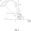
- Figs. 1 and 2 show a membrane 1 which is provided in a closed device 3, comprising a transparent lid 15 forming together a sample 5.
- the sample 5 is irradiated with light from a light emitting device 13, for example a laser light source.
- the laser light source 13 irradiates the laser light towards the membrane 1 in the closed device 3 of the sample 5 through the transparent lid 15, so as to obtain an incident area 7 on the membrane.
- the light receiving element 9 can be for example a CCD camera, CMOS camera, active pixel sensors, etc.
- the light incident area 7 can be any of a point, a line, one, two, three, etc. line pattern, square pattern, arc or circle pattern, cross pattern, Multi-(square/round) pattern, grid pattern or surface (circle spot, rectangular spot, square spot).
- the laser light source 13 and the camera 9 are mounted together on a supporting structure 17 so as to have a defined and fixed positional relationship with respect to each other.
- a Keyence LJ-V 7060 line laser scanner having a wavelength of 405 nm and a CMOS as light receiving element with a sampling rate of 8 kHz.
- the length of a laser line i.e. the incident area 7, obtained by the scanner is around 15 mm.
- the scanner can be used at a distance of 60 mm from the membrane 1.
- the sample 5 will be placed on a motion table comprising a rotation table and a linear table, which might be provided with a gripper to grab the sample 5 and to place it on a stage.
- the irradiation angle ⁇ and the imaging angle ⁇ which are formed by the optical axis of the camera with regard to the normal on the surface of the membrane, or the irradiation direction of the laser light and the normal on the surface of the membrane, respectively, are preferably different from zero. Furthermore, these angles should be different from each other.
- ⁇ and ⁇ can be selected in a wide range.
- the position of the laser light source 13 and the camera 9 can be inverted.
- the camera 9 is connected with a micro-colony detecting unit (not shown), which will receive the image information obtained from the 3D camera and process this information to detect any micro-colonies. Therefore, by detecting the light reflected, scattered and/or diffused from the membrane or the surface of the agarose medium and/or the micro-colonies on the membrane and/or the micro-colonies on the agarose medium, and by processing and evaluating the position information of the detected reflected, scattered and/ or diffused light on the 3D camera it is possible to determine the presence of micro-colonies.
- a micro-colony will have a certain growth in a direction perpendicular to the surface of the membrane. This can be detected.
- dZ dX cos ⁇ / sin ⁇ ⁇ ⁇
- dX is the variation of the position of the image of the incident area on the light-receiving element 9.
- the laser or LED light source 13 emits light so as to form a light incident area 7 in form of a line in Y direction on a flat portion of the membrane. Therefore, by performing a relative movement between the membrane 1 and the supporting structure 17 of laser light source 13 and camera 9 it is possible to scan a defined surface area of the membrane 1.
- the sample 5 is prepared as follows. At first, a membrane 1 is used in a filtration process of a liquid in, for example, a pharmaceutical process. Thereafter, the sample is used for sterility testing by scanning the entire surface of the membrane without leaving any dead areas while maintaining the closed device 3 in a closed state in order to prevent contaminations at that stage. In an alternative embodiment of the present invention, after filtration and before sterility testing, the sample 5 is placed in an adequate environment to promote the growth of micro-colonies for a period of, for example, 5 days.
- the border of the membrane is often immediately adjacent to the edge or rim 11 of the closed device 3.
- this edge or rim 11 does not block neither the laser light nor the imaging of the light incident area 7 during the scanning procedure, so that no dead areas remain and so that no artefacts due to the edge or rim 11 occur.
- Fig. 2 shows a case of approaching such an edge or rim 11 with the imaging system of Fig. 1 .
- the angle ⁇ between the incident light and the actual scanning direction is larger than 90°.
- the same relation applies for the angle ⁇ between the optical axis of the camera 9 and the scanning direction in case of approaching an edge or rim 11 of the closed device 3.
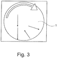
- Fig. 3 shows an example of the preferred relative movements of the sample with regard to the light source 13 and the 3D camera 9 during scanning using the device shown in Figs. 1 or 2 .
- the scanning sequence consists in scanning strips using a linear stage displacement of the sample 5.
- the rotation stage rotates the sample 5 in order to place the laser on the next sector and start the scan to the next strip, and then moves the sample in the opposite direction, that is so as to displace the incident area 7 from the border of the closed device toward the center thereof.
- the number of scans depends on the width of each scan, respectively on the width of the incident area and the field of view of the camera. Due to the positioning errors of rotating tables, the minimum number of scanned stripes should be three or more.
- a membrane scan is fast, e.g. a 47 mm membrane scan might take less than 1 min with at least a spatial resolution of 20 ⁇ m.
- the usual signal to noise ratio allows to start detecting of micro-colonies at a size of 50 ⁇ m for a setup giving a spatial pitch of 25 ⁇ m according to the Nyquist-Shannon sampling theorem.
- This theorem states, with regard to the analysis of images, that the smallest detail to be resolved has to be sampled using at least two pixels.
- the topography measurement does not matter of color and contrast but only on the shape, i.e. height and diameter.
- the present invention has the ability to detect all kind of germs, like Methylobacterium extorquens, Propionibacterium acnes, Aspergillus brasiliensis, Dekkera anomala, Pseudomonas aeruginosa.
- the incident area had been described as a line.
- the closed device 3 In order to perform the scanning through the closed lid 15 of the closed device 3, and have a light reflected from a transparent, semi-transparent or opaque membrane, the closed device 3 is arranged so as to have a determined distance between the lid 15 and the membrane 1, to have a light wavelength of ⁇ 600nm, for example 465 nm, and to perform a masking of the reflected, scattered and/or diffused light of the lid 15.
- the "far" distance between the lid 15 of the closed device 3 and the membrane 1 allows to detect any micro-colony on either HA and HV membranes or other types of membrane though the transparent lid 15 even if these membranes become semi-transparent on an agar medium (liquid or solid).
- agar medium liquid or solid
- the camera 9 can be used for taking a grey scale two-dimensional picture of an area of interest in order to diagnose the cause of each artefact.
- micro-colonies presenting a low contrast regarding the membranes for example white micro-colonies on a white membrane, it means that it will be possible to detect these micro-colonies with the scanner before a naked eye detection would be possible.
- the invention therefore allows to detect the micro-colonies with high reliability after an incubation time of typically 5 days or less.
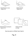
- FIG. 4 Examples of the topography given by some of micro-colonies on respective membranes 1 are depicted in Fig. 4 .
- the areas of interest can be determined.
- two-dimensional images taken by the camera 9 of the areas of interest in a gray-scale or color form can be used to further distinguish between real areas of interest, where micro-colonies are growing on the membrane 1, and artefacts, which might be caused by dust, scratches or droplets at the lid 15.
- an evaluation of the sterility of the membrane can be done in a reliable and fast manner.
- additional image information obtained by the camera is involved in the determining of the presence or absence of any micro-colony.
- the micro-colony detecting unit makes use of the color or grey scale image obtained by the camera 9, in order to distinguish more securely between artefacts and real micro-colonies.
- the detection of micro-colonies is performed by determining variation in the peak intensity value of the incident light on the membrane or the surface of the agarose or the micro-colonies on the membrane or the micro-colonies on the agarose medium by using the highest signal level for each column of the array of pixel sensor.
- the detection of contaminants is performed by determining variation in the intensity value of the incident light on the membrane or the surface of the agarose medium or the micro-colonies on the membrane or the micro-colonies on the agarose medium by using the signal level of the array of pixel sensor.
- the variation in the form of the reflected light pattern might be used.
- the detection of micro-colonies is performed by determining variation in the width (e.g. thickness of the line) of the incident light on the membrane or the surface of the agarose medium or the micro-colonies on the membrane or the micro-colonies on the agarose medium by using the number of pixels that have a signal level above a given value around the light intensity peak for each column of the array of pixel sensor.
- the wavelength of the laser is not limited to 405 nm.
- Other laser light wavelengths like 450, 465, 525, 532 nm might be used as well, although it is preferred that the laser light wavelengths should be below 600 nm.
- the angle of the incident relate respectively to the normal of the membrane is set to 5° in the illustrated first embodiment. This value can, however, be larger or smaller as long as it is different from zero.
- the angle of the optical axis of the camera in the preferred first embodiment is set to 40°. This angle might have a different value also.
- it is important that the angle is different from zero with regard to the normal to the membrane surface.
- the two above angles should be different.
- the movement of the sample in the stage was a sequence of linear and rotational movements. This has the advantage that the form of a micro-colony detected during the linear movement will be imaged accurately, without distortions due to a rotational movement.
Landscapes
- Engineering & Computer Science (AREA)
- Health & Medical Sciences (AREA)
- Life Sciences & Earth Sciences (AREA)
- Chemical & Material Sciences (AREA)
- General Health & Medical Sciences (AREA)
- Physics & Mathematics (AREA)
- General Physics & Mathematics (AREA)
- Organic Chemistry (AREA)
- Theoretical Computer Science (AREA)
- Molecular Biology (AREA)
- Zoology (AREA)
- Analytical Chemistry (AREA)
- Immunology (AREA)
- Biochemistry (AREA)
- Proteomics, Peptides & Aminoacids (AREA)
- Wood Science & Technology (AREA)
- Radiology & Medical Imaging (AREA)
- Medical Informatics (AREA)
- Nuclear Medicine, Radiotherapy & Molecular Imaging (AREA)
- Computer Vision & Pattern Recognition (AREA)
- Quality & Reliability (AREA)
- Biomedical Technology (AREA)
- Multimedia (AREA)
- Pathology (AREA)
- Bioinformatics & Cheminformatics (AREA)
- Genetics & Genomics (AREA)
- Biotechnology (AREA)
- General Engineering & Computer Science (AREA)
- Biophysics (AREA)
- Microbiology (AREA)
- Epidemiology (AREA)
- Toxicology (AREA)
- Public Health (AREA)
- Measuring Or Testing Involving Enzymes Or Micro-Organisms (AREA)
- Apparatus Associated With Microorganisms And Enzymes (AREA)
- Investigating Or Analysing Materials By Optical Means (AREA)
- Length Measuring Devices By Optical Means (AREA)
Claims (9)
- Verfahren zur Detektion von Mikro-Kolonien, die auf einer Membran (1) einer Probe (5) in einer geschlossenen Vorrichtung oder einem Agarose-Medium einer Probe (5) in einer geschlossenen Vorrichtung (3) wachsen, wobei das Verfahren die Schritte umfasst:Bestrahlen der Probe (5) mit einem Licht, das mit einem von Null verschiedenen Winkel (β) in Bezug auf die Normale zu der Membran (1) oder der Oberfläche des Agarose-Mediums von außerhalb der Vorrichtung (3) einfällt;Abbilden eines abgebildeten Einfallsbereiches (7) des Lichtes auf der Membran (1) oder der Oberfläche des Agarose-Mediums mittels eines Lichtempfangselementes (9) unter Verwendung eines Aufnahmewinkels (a), der sich von dem Lichteinfallswinkel (β) unterscheidet, in Bezug auf die Normale der Membran (1) oder die Oberfläche des Agarose-Mediums von der Außenseite der Vorrichtung (3), wobei der Bildaufnahmewinkel (α) unterschiedlich von 0 ist;Erfassen des Lichts, das von der Membran oder der Oberfläche des Agarose-Mediums und/oder den Mikro-Kolonien auf der Membran und/oder den Mikro-Kolonien auf dem Agarose-Medium reflektiert, gestreut oder zerstreut wird;wobei das Verfahren dadurch gekennzeichnet ist, dass es des Weiteren umfasst:Abtasten der Membran (1) oder der Oberfläche des Agarose-Mediums durch eine lineare und Rotationsbewegung der Probe relativ zu dem Lichtempfangselement (9); wobeidie relative Bewegung der Probe (5) relativ zu dem Lichtempfangselement (9) zumindest eine Folge umfasst mit:einer linearen Bewegung zur Verschiebung des abgebildeten Einfallsbereiches (7) von der Mitte der Probe (5) hin zu deren Rand, gefolgt durch eine Drehbewegung der Probe um deren Mittelachse und einer linearen Bewegung zur Verschiebung des abgebildeten Einfallsbereiches (7) von dem Rand der Probe (5) hin zu deren Mitte; odereiner linearen Bewegung zur Verschiebung des abgebildeten Einfallsbereichs (7) von dem Rand der Probe (5) hin zu deren Mitte, gefolgt durch eine Drehbewegung der Probe (5) um deren Mittelachse und einer linearen Bewegung zur Verschiebung des abgebildeten Einfallsbereichs (7) von der Mitte der Probe (5) hin zu deren Rand; undwobei ein Winkel (γ) zwischen dem Einfallslicht und der Richtung der linearen Bewegung zur Verschiebung des abgebildeten Einfallsbereichs (7) von der Mitte der Probe (5) hin zu deren Rand und einen Winkel () zwischen der Richtung der linearen Bewegung zur Verschiebung des abgebildeten Einfallsbereichs (7) von der Mitte der Probe (5) hin zu deren Rand und einer Bildrichtung des Lichtempfangselementes (9) eingestellt werden, um 90 Grad zu übersteigen,

- Verfahren nach Anspruch 1 unter Verwendung einer elektrisch betriebenen Lichtquelle mit einem Muster, das die Probe beleuchtet, wobei das Muster ein Punkt, eine Linie, eine Mehrzahl von Linien, ein Quadratmuster, ein Bogen- oder Kreismuster, ein Kreuzmuster, ein Mehrfach-Quadrat-/Kreismuster, ein Gittermuster oder ein zweidimensionaler Bereich, ein kreisförmiger Spot, ein rechteckiger Spot oder ein quadratischer Spot ist und wobei das Lichtempfangselement (9) einen Array von Pixelsensoren umfasst.
- Verfahren nach Anspruch 1 oder 2, mit dem Schritt des Bestimmens von Änderungen in der Höhe des abgebildeten Einfallsbereichs (7) oder der Membran (1) oder der Oberfläche des Agarose-Mediums beruhend auf der Position des Bildes des Einfallsbereiches auf dem Lichtempfangselement (9) unter Verwendung eines Triangulationsverfahrens.
- Verfahren nach Anspruch 1 oder 2, bei dem die Erfassung der Mikro-Kolonien durch Bestimmen einer Änderung in dem Licht unter Verwendung der Anzahl von Pixeln durchgeführt wird, die ein Signalpegel oberhalb eines Schwellwertes empfangen, um einen Lichtintensitätsgipfel für jede Linie oder jede Spalte eines Arrays von Pixeln des Pixelsensors.
- Verfahren nach einem der Ansprüche 1 bis 4, bei dem das Erfassen der Mikro-Kolonien durch Bestimmen der Änderung in dem Spitzenintensitätswert des Lichtes unter Verwendung des höchsten Signalpegels für jede Linie oder jede Spalte eines Arrays von Pixeln des Pixelsensors erfolgt.
- Verfahren nach einem der Ansprüche 1 bis 4, bei dem das Erfassen der Mikro-Kolonien durch Bestimmen der Änderung des Intensitätswertes des Lichts unter Verwendung des Signalpegels des Arrays des Pixelsensors erfolgt.
- Verfahren nach einem der Ansprüche 1 bis 6, mit:
Durchführen der Relativbewegung der Probe relativ zu der Lichtquelle (13) und des Lichtempfangselementes (9), um so die gesamte Membran (1) oder die gesamte Oberfläche des Agarose-Mediums zu beleuchten und abzubilden. - Verfahren nach Anspruch 1, bei dem der Winkel (6) eingestellt wird, um größer als der Winkel (γ) zu sein.
- Verfahren nach Anspruch 1, bei dem der Winkel (γ) eingestellt wird, um größer als der Winkel (ö) zu sein.
Priority Applications (1)
| Application Number | Priority Date | Filing Date | Title |
|---|---|---|---|
| PL15722049T PL3134848T3 (pl) | 2014-04-22 | 2015-03-30 | Sposób wykrywania mikrokolonii rosnących na membranie lub na pożywce agarozowej próbki oraz urządzenie do badania sterylności |
Applications Claiming Priority (2)
| Application Number | Priority Date | Filing Date | Title |
|---|---|---|---|
| EP14290114 | 2014-04-22 | ||
| PCT/EP2015/000679 WO2015161914A2 (en) | 2014-04-22 | 2015-03-30 | Method for detecting micro-colonies growing on a membrane or an agarose medium of a sample and a sterility testing apparatus |
Publications (2)
| Publication Number | Publication Date |
|---|---|
| EP3134848A2 EP3134848A2 (de) | 2017-03-01 |
| EP3134848B1 true EP3134848B1 (de) | 2019-09-04 |
Family
ID=50774791
Family Applications (1)
| Application Number | Title | Priority Date | Filing Date |
|---|---|---|---|
| EP15722049.2A Active EP3134848B1 (de) | 2014-04-22 | 2015-03-30 | Verfahren zur detektion von mikrokolonien, die auf einer membran oder einem agarosemedium einer probe wachsen, und eine sterilitätsüberprüfungsvorrichtung |
Country Status (7)
| Country | Link |
|---|---|
| US (1) | US20170044588A1 (de) |
| EP (1) | EP3134848B1 (de) |
| JP (1) | JP6550076B2 (de) |
| CN (1) | CN106462730B (de) |
| ES (1) | ES2757958T3 (de) |
| PL (1) | PL3134848T3 (de) |
| WO (1) | WO2015161914A2 (de) |
Families Citing this family (11)
| Publication number | Priority date | Publication date | Assignee | Title |
|---|---|---|---|---|
| WO2017045741A1 (en) * | 2015-09-16 | 2017-03-23 | Merck Patent Gmbh | A method for early detection and identification of microbial-colonies, apparatus for performing the method and computer program |
| CA3075267C (en) * | 2017-09-07 | 2021-01-26 | Eagle Analytical Services, Inc. | Process and system for flow cytometry fluorescent detection of reactive materials in viscous non-filterable materials |
| JP7154005B2 (ja) * | 2017-09-15 | 2022-10-17 | 株式会社島津製作所 | 菌体量測定装置、分析装置および菌体量測定方法 |
| US11867603B2 (en) * | 2018-12-31 | 2024-01-09 | Robert Bosch Gmbh | Mold detecting device using electromagnetic waves |
| EP3779882B1 (de) * | 2019-08-16 | 2022-07-20 | Sick IVP AB | Bereitstellen einer intensitätsspitzenposition in bilddaten aus der lichttriangulation in einem system zur dreidimensionalen bildgebung |
| EP4065958B1 (de) * | 2019-11-29 | 2025-04-09 | Intubio ApS | Verfahren zur analyse einer flüssigkeitsprobe für eine biologische aktivität |
| EP4083181A1 (de) * | 2021-04-26 | 2022-11-02 | Sartorius Stedim Biotech GmbH | Sterilitätsprüfungsmodul |
| JP2024515779A (ja) * | 2021-04-26 | 2024-04-10 | ザルトリウス ステディム バイオテック ゲゼルシャフト ミット ベシュレンクテル ハフツング | 無菌試験のための方法 |
| IT202200005669A1 (it) | 2022-03-22 | 2023-09-22 | Copan Italia Spa | Dispositivo e metodo per l’acquisizione di immagini di campioni biologici |
| JP2024027673A (ja) * | 2022-08-18 | 2024-03-01 | キヤノンメディカルシステムズ株式会社 | 画像処理装置、画像処理システム、画像処理方法及び画像処理プログラム |
| IT202200019200A1 (it) | 2022-09-19 | 2024-03-19 | Copan Italia Spa | Dispositivo per l’acquisizione di immagini di campioni di materiale biologico e metodo associato |
Citations (1)
| Publication number | Priority date | Publication date | Assignee | Title |
|---|---|---|---|---|
| WO2008137746A1 (en) * | 2007-05-04 | 2008-11-13 | Aperio Technologies, Inc. | Rapid microscope scanner for volume image acquisition |
Family Cites Families (11)
| Publication number | Priority date | Publication date | Assignee | Title |
|---|---|---|---|---|
| US3736432A (en) * | 1971-03-22 | 1973-05-29 | Varian Associates | Bacterial colony counting method and apparatus |
| DK2184346T3 (en) * | 2001-09-06 | 2017-06-26 | Rapid Micro Biosystems Inc | Rapid detection of replicating cells |
| US20030059866A1 (en) * | 2001-09-26 | 2003-03-27 | Kim Lewis | Isolation and cultivation of microorganisms from natural environments and drug discovery based thereon |
| JP2007139622A (ja) * | 2005-11-18 | 2007-06-07 | Olympus Corp | 3次元形状計測装置 |
| FR2958298B1 (fr) | 2010-04-06 | 2014-10-17 | Commissariat Energie Atomique | Procede de detection d'amas de particules biologiques |
| DE102010052975A1 (de) * | 2010-11-30 | 2012-05-31 | Bruker Daltonik Gmbh | Verfahren und Probenträger für die Unterstützung der händischen Präparation von Proben für eine Ionisierung mit matrix-unterstützter Laserdesorption |
| JP5692790B2 (ja) * | 2011-02-02 | 2015-04-01 | オプテックス・エフエー株式会社 | 錠剤の外観検査装置及びptp包装機 |
| JP5992456B2 (ja) * | 2011-03-03 | 2016-09-14 | カリフォルニア インスティチュート オブ テクノロジー | 装置、システム及び方法 |
| JP5857858B2 (ja) * | 2012-04-13 | 2016-02-10 | 新日鐵住金株式会社 | 形状計測装置及び形状計測方法 |
| EP2869924A1 (de) | 2012-07-03 | 2015-05-13 | Merck Patent GmbH | Vorrichtung zur probenvorbereitung |
| FR2997502B1 (fr) * | 2012-10-29 | 2014-12-26 | Commissariat Energie Atomique | Procede d'observation d'especes biologiques. |
-
2015
- 2015-03-30 ES ES15722049T patent/ES2757958T3/es active Active
- 2015-03-30 CN CN201580021046.4A patent/CN106462730B/zh active Active
- 2015-03-30 JP JP2016564204A patent/JP6550076B2/ja active Active
- 2015-03-30 WO PCT/EP2015/000679 patent/WO2015161914A2/en not_active Ceased
- 2015-03-30 EP EP15722049.2A patent/EP3134848B1/de active Active
- 2015-03-30 PL PL15722049T patent/PL3134848T3/pl unknown
- 2015-03-30 US US15/305,703 patent/US20170044588A1/en not_active Abandoned
Patent Citations (1)
| Publication number | Priority date | Publication date | Assignee | Title |
|---|---|---|---|---|
| WO2008137746A1 (en) * | 2007-05-04 | 2008-11-13 | Aperio Technologies, Inc. | Rapid microscope scanner for volume image acquisition |
Also Published As
| Publication number | Publication date |
|---|---|
| PL3134848T3 (pl) | 2020-04-30 |
| CN106462730B (zh) | 2020-10-27 |
| WO2015161914A2 (en) | 2015-10-29 |
| US20170044588A1 (en) | 2017-02-16 |
| JP2017514473A (ja) | 2017-06-08 |
| WO2015161914A8 (en) | 2016-01-21 |
| EP3134848A2 (de) | 2017-03-01 |
| ES2757958T3 (es) | 2020-04-30 |
| WO2015161914A3 (en) | 2016-03-10 |
| CN106462730A (zh) | 2017-02-22 |
| JP6550076B2 (ja) | 2019-07-24 |
Similar Documents
| Publication | Publication Date | Title |
|---|---|---|
| EP3134848B1 (de) | Verfahren zur detektion von mikrokolonien, die auf einer membran oder einem agarosemedium einer probe wachsen, und eine sterilitätsüberprüfungsvorrichtung | |
| JP5878874B2 (ja) | 生物学的有機体の時間関連顕微鏡検査のためのシステムおよび方法 | |
| JP4842473B2 (ja) | 微生物を検出し、定量し、特徴付けする装置および方法 | |
| EP2935612B1 (de) | Verfahren zur differenzierung von mikrobenkolonien auf einem bild | |
| JP6186414B2 (ja) | 固体又は半固体培地上の微生物のキャラクタリゼーション方法 | |
| CN104871177B (zh) | 检测产气微生物菌落的方法 | |
| RU2666816C2 (ru) | Оптическая система и способ для анализа в реальном времени жидкого образца | |
| KR20130038345A (ko) | 미생물 검출 시스템 및 방법 | |
| JP6608423B2 (ja) | 培養および検出装置 | |
| Ogawa et al. | Noise-free accurate count of microbial colonies by time-lapse shadow image analysis | |
| JP2017521069A (ja) | 生物学的粒子の有無を検出する方法 | |
| JP2021093951A (ja) | 微生物の判別システム | |
| JP2000069994A (ja) | 微生物検出方法および微生物検出システム | |
| JP2007097582A (ja) | 微生物計数装置 | |
| JP2009247331A (ja) | 微生物検出方法および微生物計量装置 | |
| ES2893198T3 (es) | Un método de cuantificación de la capacidad de cultivo celular bacteriano individuales usando parámetros independientes del cultivo | |
| HK1178257A (en) | System and method for time-related microscopy of biological organisms |
Legal Events
| Date | Code | Title | Description |
|---|---|---|---|
| STAA | Information on the status of an ep patent application or granted ep patent |
Free format text: STATUS: THE INTERNATIONAL PUBLICATION HAS BEEN MADE |
|
| PUAI | Public reference made under article 153(3) epc to a published international application that has entered the european phase |
Free format text: ORIGINAL CODE: 0009012 |
|
| STAA | Information on the status of an ep patent application or granted ep patent |
Free format text: STATUS: REQUEST FOR EXAMINATION WAS MADE |
|
| 17P | Request for examination filed |
Effective date: 20160912 |
|
| AK | Designated contracting states |
Kind code of ref document: A2 Designated state(s): AL AT BE BG CH CY CZ DE DK EE ES FI FR GB GR HR HU IE IS IT LI LT LU LV MC MK MT NL NO PL PT RO RS SE SI SK SM TR |
|
| AX | Request for extension of the european patent |
Extension state: BA ME |
|
| RIN1 | Information on inventor provided before grant (corrected) |
Inventor name: OLIVIER, STEPHANE Inventor name: WOEHL, PIERRE Inventor name: BOUTHILLON, MARINE Inventor name: FELDEN, LUC Inventor name: ALLARD, FLORIAN Inventor name: GUEDON, PIERRE |
|
| RIN1 | Information on inventor provided before grant (corrected) |
Inventor name: BOUTHILLON, MARINE Inventor name: ALLARD, FLORIAN Inventor name: GUEDON, PIERRE Inventor name: WOEHL, PIERRE Inventor name: OLIVIER, STEPHANE Inventor name: FELDEN, LUC |
|
| DAV | Request for validation of the european patent (deleted) | ||
| DAX | Request for extension of the european patent (deleted) | ||
| STAA | Information on the status of an ep patent application or granted ep patent |
Free format text: STATUS: EXAMINATION IS IN PROGRESS |
|
| 17Q | First examination report despatched |
Effective date: 20180518 |
|
| GRAP | Despatch of communication of intention to grant a patent |
Free format text: ORIGINAL CODE: EPIDOSNIGR1 |
|
| STAA | Information on the status of an ep patent application or granted ep patent |
Free format text: STATUS: GRANT OF PATENT IS INTENDED |
|
| INTG | Intention to grant announced |
Effective date: 20190325 |
|
| GRAS | Grant fee paid |
Free format text: ORIGINAL CODE: EPIDOSNIGR3 |
|
| GRAA | (expected) grant |
Free format text: ORIGINAL CODE: 0009210 |
|
| STAA | Information on the status of an ep patent application or granted ep patent |
Free format text: STATUS: THE PATENT HAS BEEN GRANTED |
|
| AK | Designated contracting states |
Kind code of ref document: B1 Designated state(s): AL AT BE BG CH CY CZ DE DK EE ES FI FR GB GR HR HU IE IS IT LI LT LU LV MC MK MT NL NO PL PT RO RS SE SI SK SM TR |
|
| REG | Reference to a national code |
Ref country code: GB Ref legal event code: FG4D |
|
| REG | Reference to a national code |
Ref country code: CH Ref legal event code: EP |
|
| REG | Reference to a national code |
Ref country code: AT Ref legal event code: REF Ref document number: 1176417 Country of ref document: AT Kind code of ref document: T Effective date: 20190915 |
|
| REG | Reference to a national code |
Ref country code: DE Ref legal event code: R096 Ref document number: 602015037139 Country of ref document: DE Ref country code: IE Ref legal event code: FG4D |
|
| REG | Reference to a national code |
Ref country code: CH Ref legal event code: NV Representative=s name: E. BLUM AND CO. AG PATENT- UND MARKENANWAELTE , CH |
|
| REG | Reference to a national code |
Ref country code: SE Ref legal event code: TRGR |
|
| REG | Reference to a national code |
Ref country code: NL Ref legal event code: FP |
|
| REG | Reference to a national code |
Ref country code: LT Ref legal event code: MG4D |
|
| PG25 | Lapsed in a contracting state [announced via postgrant information from national office to epo] |
Ref country code: FI Free format text: LAPSE BECAUSE OF FAILURE TO SUBMIT A TRANSLATION OF THE DESCRIPTION OR TO PAY THE FEE WITHIN THE PRESCRIBED TIME-LIMIT Effective date: 20190904 Ref country code: NO Free format text: LAPSE BECAUSE OF FAILURE TO SUBMIT A TRANSLATION OF THE DESCRIPTION OR TO PAY THE FEE WITHIN THE PRESCRIBED TIME-LIMIT Effective date: 20191204 Ref country code: BG Free format text: LAPSE BECAUSE OF FAILURE TO SUBMIT A TRANSLATION OF THE DESCRIPTION OR TO PAY THE FEE WITHIN THE PRESCRIBED TIME-LIMIT Effective date: 20191204 Ref country code: HR Free format text: LAPSE BECAUSE OF FAILURE TO SUBMIT A TRANSLATION OF THE DESCRIPTION OR TO PAY THE FEE WITHIN THE PRESCRIBED TIME-LIMIT Effective date: 20190904 Ref country code: LT Free format text: LAPSE BECAUSE OF FAILURE TO SUBMIT A TRANSLATION OF THE DESCRIPTION OR TO PAY THE FEE WITHIN THE PRESCRIBED TIME-LIMIT Effective date: 20190904 |
|
| PG25 | Lapsed in a contracting state [announced via postgrant information from national office to epo] |
Ref country code: RS Free format text: LAPSE BECAUSE OF FAILURE TO SUBMIT A TRANSLATION OF THE DESCRIPTION OR TO PAY THE FEE WITHIN THE PRESCRIBED TIME-LIMIT Effective date: 20190904 Ref country code: LV Free format text: LAPSE BECAUSE OF FAILURE TO SUBMIT A TRANSLATION OF THE DESCRIPTION OR TO PAY THE FEE WITHIN THE PRESCRIBED TIME-LIMIT Effective date: 20190904 Ref country code: AL Free format text: LAPSE BECAUSE OF FAILURE TO SUBMIT A TRANSLATION OF THE DESCRIPTION OR TO PAY THE FEE WITHIN THE PRESCRIBED TIME-LIMIT Effective date: 20190904 Ref country code: GR Free format text: LAPSE BECAUSE OF FAILURE TO SUBMIT A TRANSLATION OF THE DESCRIPTION OR TO PAY THE FEE WITHIN THE PRESCRIBED TIME-LIMIT Effective date: 20191205 |
|
| REG | Reference to a national code |
Ref country code: AT Ref legal event code: MK05 Ref document number: 1176417 Country of ref document: AT Kind code of ref document: T Effective date: 20190904 |
|
| REG | Reference to a national code |
Ref country code: ES Ref legal event code: FG2A Ref document number: 2757958 Country of ref document: ES Kind code of ref document: T3 Effective date: 20200430 |
|
| PG25 | Lapsed in a contracting state [announced via postgrant information from national office to epo] |
Ref country code: EE Free format text: LAPSE BECAUSE OF FAILURE TO SUBMIT A TRANSLATION OF THE DESCRIPTION OR TO PAY THE FEE WITHIN THE PRESCRIBED TIME-LIMIT Effective date: 20190904 Ref country code: PT Free format text: LAPSE BECAUSE OF FAILURE TO SUBMIT A TRANSLATION OF THE DESCRIPTION OR TO PAY THE FEE WITHIN THE PRESCRIBED TIME-LIMIT Effective date: 20200106 Ref country code: RO Free format text: LAPSE BECAUSE OF FAILURE TO SUBMIT A TRANSLATION OF THE DESCRIPTION OR TO PAY THE FEE WITHIN THE PRESCRIBED TIME-LIMIT Effective date: 20190904 Ref country code: AT Free format text: LAPSE BECAUSE OF FAILURE TO SUBMIT A TRANSLATION OF THE DESCRIPTION OR TO PAY THE FEE WITHIN THE PRESCRIBED TIME-LIMIT Effective date: 20190904 |
|
| PG25 | Lapsed in a contracting state [announced via postgrant information from national office to epo] |
Ref country code: SK Free format text: LAPSE BECAUSE OF FAILURE TO SUBMIT A TRANSLATION OF THE DESCRIPTION OR TO PAY THE FEE WITHIN THE PRESCRIBED TIME-LIMIT Effective date: 20190904 Ref country code: SM Free format text: LAPSE BECAUSE OF FAILURE TO SUBMIT A TRANSLATION OF THE DESCRIPTION OR TO PAY THE FEE WITHIN THE PRESCRIBED TIME-LIMIT Effective date: 20190904 Ref country code: CZ Free format text: LAPSE BECAUSE OF FAILURE TO SUBMIT A TRANSLATION OF THE DESCRIPTION OR TO PAY THE FEE WITHIN THE PRESCRIBED TIME-LIMIT Effective date: 20190904 Ref country code: IS Free format text: LAPSE BECAUSE OF FAILURE TO SUBMIT A TRANSLATION OF THE DESCRIPTION OR TO PAY THE FEE WITHIN THE PRESCRIBED TIME-LIMIT Effective date: 20200224 |
|
| REG | Reference to a national code |
Ref country code: DE Ref legal event code: R097 Ref document number: 602015037139 Country of ref document: DE |
|
| PLBE | No opposition filed within time limit |
Free format text: ORIGINAL CODE: 0009261 |
|
| STAA | Information on the status of an ep patent application or granted ep patent |
Free format text: STATUS: NO OPPOSITION FILED WITHIN TIME LIMIT |
|
| PG2D | Information on lapse in contracting state deleted |
Ref country code: IS |
|
| PG25 | Lapsed in a contracting state [announced via postgrant information from national office to epo] |
Ref country code: DK Free format text: LAPSE BECAUSE OF FAILURE TO SUBMIT A TRANSLATION OF THE DESCRIPTION OR TO PAY THE FEE WITHIN THE PRESCRIBED TIME-LIMIT Effective date: 20190904 Ref country code: IS Free format text: LAPSE BECAUSE OF FAILURE TO SUBMIT A TRANSLATION OF THE DESCRIPTION OR TO PAY THE FEE WITHIN THE PRESCRIBED TIME-LIMIT Effective date: 20200105 |
|
| 26N | No opposition filed |
Effective date: 20200605 |
|
| PG25 | Lapsed in a contracting state [announced via postgrant information from national office to epo] |
Ref country code: SI Free format text: LAPSE BECAUSE OF FAILURE TO SUBMIT A TRANSLATION OF THE DESCRIPTION OR TO PAY THE FEE WITHIN THE PRESCRIBED TIME-LIMIT Effective date: 20190904 |
|
| PG25 | Lapsed in a contracting state [announced via postgrant information from national office to epo] |
Ref country code: MC Free format text: LAPSE BECAUSE OF FAILURE TO SUBMIT A TRANSLATION OF THE DESCRIPTION OR TO PAY THE FEE WITHIN THE PRESCRIBED TIME-LIMIT Effective date: 20190904 |
|
| PG25 | Lapsed in a contracting state [announced via postgrant information from national office to epo] |
Ref country code: LU Free format text: LAPSE BECAUSE OF NON-PAYMENT OF DUE FEES Effective date: 20200330 |
|
| REG | Reference to a national code |
Ref country code: DE Ref legal event code: R079 Ref document number: 602015037139 Country of ref document: DE Free format text: PREVIOUS MAIN CLASS: G06K0009000000 Ipc: G06V0010000000 |
|
| PG25 | Lapsed in a contracting state [announced via postgrant information from national office to epo] |
Ref country code: TR Free format text: LAPSE BECAUSE OF FAILURE TO SUBMIT A TRANSLATION OF THE DESCRIPTION OR TO PAY THE FEE WITHIN THE PRESCRIBED TIME-LIMIT Effective date: 20190904 Ref country code: MT Free format text: LAPSE BECAUSE OF FAILURE TO SUBMIT A TRANSLATION OF THE DESCRIPTION OR TO PAY THE FEE WITHIN THE PRESCRIBED TIME-LIMIT Effective date: 20190904 Ref country code: CY Free format text: LAPSE BECAUSE OF FAILURE TO SUBMIT A TRANSLATION OF THE DESCRIPTION OR TO PAY THE FEE WITHIN THE PRESCRIBED TIME-LIMIT Effective date: 20190904 |
|
| PG25 | Lapsed in a contracting state [announced via postgrant information from national office to epo] |
Ref country code: MK Free format text: LAPSE BECAUSE OF FAILURE TO SUBMIT A TRANSLATION OF THE DESCRIPTION OR TO PAY THE FEE WITHIN THE PRESCRIBED TIME-LIMIT Effective date: 20190904 |
|
| P01 | Opt-out of the competence of the unified patent court (upc) registered |
Effective date: 20230518 |
|
| PGFP | Annual fee paid to national office [announced via postgrant information from national office to epo] |
Ref country code: ES Payment date: 20250403 Year of fee payment: 11 |
|
| PGFP | Annual fee paid to national office [announced via postgrant information from national office to epo] |
Ref country code: CH Payment date: 20250401 Year of fee payment: 11 |
|
| PGFP | Annual fee paid to national office [announced via postgrant information from national office to epo] |
Ref country code: NL Payment date: 20260219 Year of fee payment: 12 |
|
| REG | Reference to a national code |
Ref country code: CH Ref legal event code: U11 Free format text: ST27 STATUS EVENT CODE: U-0-0-U10-U11 (AS PROVIDED BY THE NATIONAL OFFICE) Effective date: 20260401 |
|
| PGFP | Annual fee paid to national office [announced via postgrant information from national office to epo] |
Ref country code: SE Payment date: 20260219 Year of fee payment: 12 |
|
| PGFP | Annual fee paid to national office [announced via postgrant information from national office to epo] |
Ref country code: GB Payment date: 20260220 Year of fee payment: 12 |
|
| PGFP | Annual fee paid to national office [announced via postgrant information from national office to epo] |
Ref country code: DE Payment date: 20260219 Year of fee payment: 12 Ref country code: IE Payment date: 20260223 Year of fee payment: 12 |
|
| PGFP | Annual fee paid to national office [announced via postgrant information from national office to epo] |
Ref country code: BE Payment date: 20260219 Year of fee payment: 12 Ref country code: IT Payment date: 20260219 Year of fee payment: 12 |
|
| PGFP | Annual fee paid to national office [announced via postgrant information from national office to epo] |
Ref country code: FR Payment date: 20260219 Year of fee payment: 12 |
|
| PGFP | Annual fee paid to national office [announced via postgrant information from national office to epo] |
Ref country code: PL Payment date: 20260227 Year of fee payment: 12 |