EP3134876B1 - Appareil équipé d'un capteur d'empreinte digitale - Google Patents
Appareil équipé d'un capteur d'empreinte digitale Download PDFInfo
- Publication number
- EP3134876B1 EP3134876B1 EP15720644.2A EP15720644A EP3134876B1 EP 3134876 B1 EP3134876 B1 EP 3134876B1 EP 15720644 A EP15720644 A EP 15720644A EP 3134876 B1 EP3134876 B1 EP 3134876B1
- Authority
- EP
- European Patent Office
- Prior art keywords
- handle
- fingerprint sensor
- axis
- thumb
- hand
- Prior art date
- Legal status (The legal status is an assumption and is not a legal conclusion. Google has not performed a legal analysis and makes no representation as to the accuracy of the status listed.)
- Active
Links
Images


Classifications
-
- G—PHYSICS
- G06—COMPUTING OR CALCULATING; COUNTING
- G06V—IMAGE OR VIDEO RECOGNITION OR UNDERSTANDING
- G06V40/00—Recognition of biometric, human-related or animal-related patterns in image or video data
- G06V40/10—Human or animal bodies, e.g. vehicle occupants or pedestrians; Body parts, e.g. hands
- G06V40/12—Fingerprints or palmprints
- G06V40/1382—Detecting the live character of the finger, i.e. distinguishing from a fake or cadaver finger
- G06V40/1394—Detecting the live character of the finger, i.e. distinguishing from a fake or cadaver finger using acquisition arrangements
-
- G—PHYSICS
- G06—COMPUTING OR CALCULATING; COUNTING
- G06V—IMAGE OR VIDEO RECOGNITION OR UNDERSTANDING
- G06V40/00—Recognition of biometric, human-related or animal-related patterns in image or video data
- G06V40/10—Human or animal bodies, e.g. vehicle occupants or pedestrians; Body parts, e.g. hands
- G06V40/12—Fingerprints or palmprints
-
- A—HUMAN NECESSITIES
- A63—SPORTS; GAMES; AMUSEMENTS
- A63F—CARD, BOARD, OR ROULETTE GAMES; INDOOR GAMES USING SMALL MOVING PLAYING BODIES; VIDEO GAMES; GAMES NOT OTHERWISE PROVIDED FOR
- A63F13/00—Video games, i.e. games using an electronically generated display having two or more dimensions
- A63F13/70—Game security or game management aspects
- A63F13/73—Authorising game programs or game devices, e.g. checking authenticity
-
- G—PHYSICS
- G01—MEASURING; TESTING
- G01L—MEASURING FORCE, STRESS, TORQUE, WORK, MECHANICAL POWER, MECHANICAL EFFICIENCY, OR FLUID PRESSURE
- G01L5/00—Apparatus for, or methods of, measuring force, work, mechanical power, or torque, specially adapted for specific purposes
- G01L5/0028—Force sensors associated with force applying means
- G01L5/0038—Force sensors associated with force applying means applying a pushing force
-
- G—PHYSICS
- G06—COMPUTING OR CALCULATING; COUNTING
- G06V—IMAGE OR VIDEO RECOGNITION OR UNDERSTANDING
- G06V10/00—Arrangements for image or video recognition or understanding
- G06V10/10—Image acquisition
- G06V10/12—Details of acquisition arrangements; Constructional details thereof
-
- G—PHYSICS
- G06—COMPUTING OR CALCULATING; COUNTING
- G06V—IMAGE OR VIDEO RECOGNITION OR UNDERSTANDING
- G06V40/00—Recognition of biometric, human-related or animal-related patterns in image or video data
- G06V40/10—Human or animal bodies, e.g. vehicle occupants or pedestrians; Body parts, e.g. hands
- G06V40/12—Fingerprints or palmprints
- G06V40/13—Sensors therefor
-
- G—PHYSICS
- G06—COMPUTING OR CALCULATING; COUNTING
- G06V—IMAGE OR VIDEO RECOGNITION OR UNDERSTANDING
- G06V40/00—Recognition of biometric, human-related or animal-related patterns in image or video data
- G06V40/40—Spoof detection, e.g. liveness detection
- G06V40/45—Detection of the body part being alive
-
- G—PHYSICS
- G07—CHECKING-DEVICES
- G07C—TIME OR ATTENDANCE REGISTERS; REGISTERING OR INDICATING THE WORKING OF MACHINES; GENERATING RANDOM NUMBERS; VOTING OR LOTTERY APPARATUS; ARRANGEMENTS, SYSTEMS OR APPARATUS FOR CHECKING NOT PROVIDED FOR ELSEWHERE
- G07C9/00—Individual registration on entry or exit
- G07C9/30—Individual registration on entry or exit not involving the use of a pass
- G07C9/32—Individual registration on entry or exit not involving the use of a pass in combination with an identity check
- G07C9/37—Individual registration on entry or exit not involving the use of a pass in combination with an identity check using biometric data, e.g. fingerprints, iris scans or voice recognition
-
- G—PHYSICS
- G07—CHECKING-DEVICES
- G07F—COIN-FREED OR LIKE APPARATUS
- G07F17/00—Coin-freed apparatus for hiring articles; Coin-freed facilities or services
- G07F17/32—Coin-freed apparatus for hiring articles; Coin-freed facilities or services for games, toys, sports, or amusements
- G07F17/3241—Security aspects of a gaming system, e.g. detecting cheating, device integrity, surveillance
-
- H—ELECTRICITY
- H04—ELECTRIC COMMUNICATION TECHNIQUE
- H04M—TELEPHONIC COMMUNICATION
- H04M1/00—Substation equipment, e.g. for use by subscribers
- H04M1/02—Constructional features of telephone sets
- H04M1/0202—Portable telephone sets, e.g. cordless phones, mobile phones or bar type handsets
-
- H—ELECTRICITY
- H04—ELECTRIC COMMUNICATION TECHNIQUE
- H04M—TELEPHONIC COMMUNICATION
- H04M2250/00—Details of telephonic subscriber devices
- H04M2250/12—Details of telephonic subscriber devices including a sensor for measuring a physical value, e.g. temperature or motion
Definitions
- the present invention relates generally to devices having a fingerprint sensor.
- the present invention relates to devices in which the fingerprint sensor is associated with a handle or palm rest.
- Such devices with a fingerprint sensor can in particular be gaming and/or entertainment and/or betting machines, such as those used in casinos or amusement arcades, or devices such as vending machines that operate with money or monetary value, where goods or Game chips can be bought, or access control systems such as turnstiles or access barrier systems.
- the fingerprint sensor generally serves to identify the user of the respective device, with the biometric data recorded by the fingerprint sensor, for example of the thumb or a fingertip, being able to be used in various ways.
- an enabling device that can be connected to the fingerprint sensor can enable a device function depending on the recorded fingerprint, for example unlocking a device lock or releasing an access barrier if the recorded fingerprint corresponds to a stored fingerprint or is sufficiently close or conversely sufficiently different from a stored fingerprint, i.e
- the fingerprint can be used to check whether an authorized or a blocked person is trying to operate the device.
- the fingerprint sensor can also be connected to a device setting device, with the help of which personal device settings such as screen position, character and/or letter size or other image display options or, for example, a game preselection based on the captured fingerprint can be customized for the user can be preconfigured.
- the fingerprint sensor can also be connected to a user detection device, which is detected as a function of the fingerprint in each case Attributes usage data to an individual user account - such as storing usage times or winnings in a user account or debiting stakes from a user account depending on the respective fingerprint.
- a coin-operated device in the form of a slot machine in which a fingerprint sensor is integrated into the start switch of the device, with which a game can be started on the entertainment device.
- a miniature camera or a CCD area sensor provided in the touch surface of said start button captures the fingerprint of the user pressing the start button, which fingerprint captured is then compared with previously stored fingerprints to check whether an authorized user activates the entertainment device. Since the start switch is simultaneously pressed when the finger or thumb is placed on the fingerprint sensor, placing it on the fingerprint sensor is sometimes too impetuous or the finger can slip, so that the biometric data cannot be recorded properly.
- a door handle is also known in which a fingerprint sensor is integrated in order to unlock an electronic door lock as a function of the detected fingerprint.
- the fingerprint sensor is provided on a front side of the handle facing the user in the region of the axis of rotation of the door handle.
- similar problems can arise here. When turning the door handle, the thumb to be placed on the fingerprint sensor can slip so that the biometric data cannot be recorded properly.
- a gaming machine which comprises a separate operating tablet which can be connected to a gaming computer system by cable.
- a magnetic stripe card laser should be provided on the control tablet, which should be assigned a fingerprint sensor in order to increase security.
- the present invention is therefore based on the object of an improved device to create the type mentioned above, which avoids the disadvantages of the prior art and develops the latter in an advantageous manner.
- the handling and usability of the fingerprint sensor on the device should be simplified.
- the fingerprint sensor is arranged at a distance from the handle in the vicinity of the handle in such a way that when the handle is gripped with the index and/or middle and/or ring and/or little finger of one hand, the thumb of this hand opens next to the handle the fingerprint sensor can be placed.
- a longitudinal axis of the thumbtip of the thumb essentially coincides with a main axis of the fingerprint sensor.
- the fingerprint sensor can be arranged directly on a device housing that adjoins the handle or extends in the vicinity of the handle, with the device housing being able, for example, to enclose a body part of the device surrounding the handle and/or to form a mounting base for the handle can.
- the fingerprint sensor can be placed on the device housing.
- the fingerprint sensor can also be embedded in the device housing or sunk into the housing. That is, the fingerprint sensor is set back or recessed from the surrounding housing surface.
- the fingerprint sensor can also be provided on a device part that is separate from the device housing - e.g .
- the fingerprint sensor can be arranged offset from the handle, in particular transversely to the longitudinal axis of the handle. If the handle is aligned horizontally in a development of the invention, the fingerprint sensor can advantageously be arranged below the handle. If the handle is alternatively aligned upright, the fingerprint sensor can be arranged to the left of the handle for right-handed gripping and to the right of the handle for left-handed gripping, with such a fingerprint sensor being able to be provided on both sides of the handle for gripping the handle on both sides.
- the handle is designed to be position-changeable in the invention so that the handle can be brought into two different working positions relative to the fingerprint sensor.
- One of these working positions with regard to the fingerprint sensor is such that the right thumb can be placed on the fingerprint sensor.
- the other working position is such that the left thumb can be placed on the fingerprint sensor.
- the handle can be locked in the respective working position, so that one hand can be stably supported.
- the handle can, for example, be designed or mounted so that it can be repositioned so that it can be brought into two different positions by repositioning.
- the handle can also be pivotably mounted so that it can be pivoted back and forth between the two aforementioned working positions.
- the handle can also be slidably mounted, for example along its longitudinal axis, so that it comes to rest primarily on the left and on the other hand primarily on the right of the fingerprint sensor and accordingly can be used either for the left hand or the right hand to match the fingerprint sensor. sensor is positioned.
- a parking position or non-working position of the handle in addition to at least one working position in which the thumb can be placed on the fingerprint sensor, can also be provided, in which the handle is lowered into the body of the device, for example, or placed directly in a non-interfering place.
- the fingerprint sensor can also be in the longitudinal direction of the handle from the handle or a gripping section of the handle that is for the ball of the hand or index and/or middle and/or ring and/or little finger is provided, be arranged spaced apart, in particular be shifted a little beyond the end of the handle or gripping section, which is intended to be gripped by the index finger, so that the ball of the hand extends obliquely beyond the end of the handle protruding thumb comes to rest with the tip of the thumb or the last phalanx of the thumb on the fingerprint sensor when the hand grips the handle with the fingers.
- the spacing of the fingerprint sensor from the handle or its gripping section is advantageously limited to the usual thumb reach of an average-sized hand and can be a few centimeters transverse to the longitudinal axis of the handle and/or in the direction of the longitudinal axis of the handle.
- the fingerprint sensor can be arranged with a main axis tilted relative to the longitudinal axis of the handle, in particular inclined at an acute angle .
- the named main axis of the fingerprint sensor can be a longitudinal central axis of the bearing surface of the fingerprint sensor and/or a main axis of the image sensor system of the fingerprint sensor, in which the evaluation device of the fingerprint sensor expects a main axis of the print image, in particular the longitudinal axis of the thumb pad .
- the fingerprint sensor can be arranged uniaxially or multiaxially tilted or inclined at an acute angle relative to the longitudinal axis of the handle, it also being possible for said main axis of the fingerprint sensor to be aligned crookedly relative to the handle.
- the main axis of the fingerprint sensor can be tilted at an acute angle relative to the longitudinal axis of the handle about a tilting axis that is aligned essentially perpendicularly to the bearing surface of the fingerprint sensor and/or perpendicularly to the device housing surrounding the fingerprint sensor.
- said main axis of the fingerprint sensor can also be tilted relative to the longitudinal axis of the handle about a tilting axis that extends at least approximately parallel to the bearing surface of the fingerprint sensor and/or parallel to the device housing surrounding the fingerprint sensor.
- the inclination or tilting of said main axis relative to the longitudinal axis of the handle can in principle be dimensioned differently, with the inclination relative to the longitudinal axis of the handle or the axes mentioned being in the range of 5 degrees to 35 degrees in order to achieve an ergonomically natural contact of the thumb on the fingerprint sensor.
- the contouring of the handle which, for example, can be slightly curved—other inclinations can also be advantageous.
- the fingerprint sensor can have an upright support surface for the thumb.
- the fingerprint sensor can have a contact surface that lies in a plane or nestles against a plane, which plane can be inclined at an acute angle to the longitudinal axis of the handle, e.g. inclined at an angle of 10-30 degrees.
- Said plane and the handle can define a wedge that converges approximately in the area of the ball of the hand, ie the contact surface spreads further away from the handle as the distance from the handle increases.
- the fingerprint sensor can be arranged on an at least approximately upright front side of the device facing the user of the device, so that the fingerprint sensor faces a user standing in front of the device and a thumb tip facing away from the user's body points to the Fingerprint sensor can be placed.
- slot machines or other devices of the type mentioned at the outset also have a storage area for the fingers of an open hand, i.e. the index, middle, ring and/or little fingers, as an alternative or in addition to the handles mentioned, so that the user of the device the flat hand can be placed on the support surface mentioned.
- Operating buttons can be provided on this support surface - such as a push button switch or a rocker switch, with which device functions can be controlled.
- Such a support surface may be provided on a prone housing section, such as a prone oriented keyboard section.
- such a support surface for the outstretched fingers of one hand can also be arranged on an upright side surface, for example in order to be able to actuate the pinball wings on a pinball machine on which the actuating buttons for the pinball wings are attached on the right and left side .
- the fingerprint sensor can be on a side of the device housing that faces a side of the device housing on which a support surface for the index and/or middle and/or ring and/or little finger is provided. inclined at an acute or obtuse angle, be arranged in such a way that when you place your index and/or middle finger and/or ring finger and/or little finger on the storage surface on one side of the device housing, your thumb can be placed on the fingerprint sensor on the other side of the device housing .
- the fingerprint sensor and the storage area for the index and/or middle and/or ring and/or little fingers are separated from one another by a housing edge, which can optionally be rounded, and are arranged on housing sides oriented towards different sides. While the outstretched fingers of a hand rest on one side of the device housing, the thumb can grip around a corner of the housing in a natural position, so to speak, and rest on the fingerprint sensor around the edge of the housing, so to speak.
- the two sides of the housing on which the support surface mentioned is arranged on the one hand and the fingerprint sensor on the other hand can be aligned at least approximately at right angles to one another.
- the fingerprint sensor can be arranged on an upright side of the housing.
- the other side of the housing, on which the resting surface for the remaining fingers of the hand is provided, can be aligned lying down, but can also extend upright.
- Said support surface can be smooth and flat or also contoured in a slightly relief-like manner like a fingerprint bed, in order to promote an intuitive placing of the outstretched fingers in the right place.
- An actuating button or an actuating element for inputting control commands or other information can be attached to the device on the named support surface for the index and/or middle finger and/or ring finger and/or little finger, so that the hand that is placed on it on the contact surface can simultaneously activate the actuating element while the thumb gripping around the edge is being scanned by the fingerprint sensor.
- the fingerprint sensor can have a main axis - which in the aforementioned manner can be a central longitudinal axis of the bearing surface of the fingerprint sensor or an expected main axis of the fingerprint image in the aforementioned manner - inclined at an acute angle to the longitudinal direction of the housing edge separating or connecting the two housing sides be aligned, whereby the acute-angled inclination of the main axis of the fingerprint sensor can be uniaxially or biaxially tilted in relation to said device edge, in which case the tilting can be analogous to the tilting described above in relation to the longitudinal axis of the handle, so that in order to avoid Repetitions may be referred to the previous description.
- the fingerprint sensor is not rigidly arranged or aligned in a fixed position relative to the handle or relative to the finger support surface, but is movably arranged or movably mounted in order to individually - that is, for the respective user and his hand - suitable positions to be able to be spent.
- the fingerprint sensor can be mounted such that it can be rotated or tilted about at least one axis of rotation, with an advantageous development of the invention being able to tilt about a tilting axis that is oriented at least approximately perpendicular to the contact surface of the fingerprint sensor and/or about a tilting axis that can be provided at least approximately parallel to a plane in which the storage surface of the fingerprint sensor lies or against which the storage surface nestles.
- the fingerprint sensor when arranged on an upright side of the housing, can be tiltable about an upright tilting axis and/or tiltable or rotatable about a horizontal tilting axis that extends parallel to the upright side of the housing on which the fingerprint sensor is arranged.
- the fingerprint sensor can also be tiltable or rotatable about a horizontal tilting axis extending essentially perpendicularly to the side of the housing on which the fingerprint sensor is arranged.
- the fingerprint sensor can also be mounted in a translationally displaceable manner, in particular in a plane approximately parallel to the side of the housing on which the fingerprint sensor is provided.
- the fingerprint sensor can be moved up and down and/or to the right and left on an upright device housing front side in order to be in an optimal position relative to the handle or the previously described contact surface for the fingers. If the fingerprint sensor is arranged on a side of the device housing that is aligned in a horizontal position, the fingerprint sensor can be displaced to the right and left and/or to the front and back.
- the fingerprint sensor and said handle or said finger support surface can be arranged directly on the device housing of the slot machine or the main device.
- the device having a finger rest surface can also be designed as a separate input device that has an interface for connecting to the main device, for example in the form of a slot machine or a PC.
- Said interface can, for example, include a serial interface, for example in the form of a USB interface or a LAN or WLAN interface.
- a device embodying the invention can be designed, for example, as a gaming and/or entertainment device such as is used in casinos or amusement arcades, the device being e.g. can be designed as a stand-alone device.
- the device 1 can include a device housing 2 which—roughly speaking—can be designed approximately in the form of a cube, but it can also be sculptural.
- a screen 3 can be arranged, but also other display means such as rotating rollers can be provided.
- a device housing section 4 which is advantageously aligned horizontally and can be shaped like a panel, for example, can function as an operating section, with input means being provided on said device housing section 4, for example in the form of control buttons or touchscreen elements.
- said device housing section 4 which viewed as a whole can be aligned lying down, comprise a handle 6, which can be arranged lying on a front side of the device housing section 4.
- said handle 6 - roughly speaking - be rod-shaped and / or be arranged on a housing edge 19, which connects a lying top 8 and an upright front 9 of the device housing section 4.
- the device housing section 4 can include a recess 10 around the handle 6, so that a hand 20 can grip the handle 6 with the index, middle, ring and little fingers.
- the necessary free space for gripping around the handle 6 can also be achieved, for example, by an arcuate or projecting contouring of the handle 6, so that the mentioned recess 10 is not mandatory.
- the handle 6 can be assigned a fingerprint sensor 5 which is arranged at a distance from one end of the handle 6 transversely to the longitudinal axis 11 of the handle 6 and also in the direction of said longitudinal axis 11 .
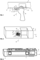
- said fingerprint sensor 5 can be arranged on the upright front side 9 of the device housing section 4, with the fingerprint sensor 5 being a little way below the handle 6 to one side of the handle 6 away - according to figure 2 to the left - can be arranged, so that a thumb 12 which does not grip the handle 6 but spreads away from the handle 6 comes to rest on the named fingerprint sensor 5 with a natural, intuitive thumb position.
- the distance of the fingerprint sensor 5 from said handle 6 transversely to the longitudinal axis 11 of the handle and/or in the direction of the longitudinal axis 11 of the handle from the end of the handle is advantageously the distance between the tip of the thumb and the root joint of the index finger, ie the usual thumb reach with the thumb spread and can be a few centimetres.
- the fingerprint sensor 5 can be arranged with a main axis 13 tilted at an acute angle relative to the longitudinal axis 11 of the handle by an angle ⁇ , wherein said angle ⁇ can be 5 to 35 degrees, for example, and is in particular dimensioned such that the main axis 13 of the Corresponds to the longitudinal axis of the thumb with a natural thumb position.
- the fingerprint sensor 5 can advantageously have a thumb guide 25 for easier positioning of the thumb on the fingerprint sensor 5 .
- lateral walls or elevations can be present that run parallel to the main axis 13 and thus guide the thumb laterally (left and right), so that the thumb is optimally oriented in relation to a bearing surface 21 of the fingerprint sensor 5 .
- a front guide wall can be present, which is arranged transversely to the main axis 13 and forms a stop for the thumb, ie the stop prevents the thumb from being pushed further into the fingerprint sensor 5 in the direction of the main axis 13 .
- the thumb guide 25 is designed in one piece as a thumb recess, insofar as the thumb is guided laterally (left and right) and at the same time the thumb is limited at the front, ie the tip of the thumb.
- the fingerprint sensor 5 can be tilted out of the front side 9 with its bearing surface 21 or its main axis 13.
- This tilting with respect to an upright tilting axis 15 parallel to the front side is shown in FIG figure 1 seen acute angle ⁇ with respect to the longitudinal axis of the handle 11.
- This tilt can also be in the range of about two (2) to 35 degrees.
- the contact surface of the fingerprint sensor 5 can also be tilted about a horizontal tilting axis 16 with respect to the front side 9 of the device housing or the longitudinal axis 11 of the handle.
- the fingerprint sensor 5 is not rigidly fixed in its alignment with respect to the handle 6, but is mounted such that it can rotate or tilt.
- a rotatability or tiltability can be provided with respect to one, several or all of the aforementioned tilting axes 14, 15 and 16, whereby the rotatability can be such that the fingerprint sensor 5 can be brought into different rotational or tilted positions, in which he then automatically or self-locking holds his position or can be fixed by fixing means.
- a return to a neutral starting position is also possible, for example by means of spring means assigned to the tilting axes 14, 15 and 16. It can be mentioned that the ability to tilt or, in particular, the ability to rotate can be supported by a thumb guide arranged on the fingerprint sensor 5 .
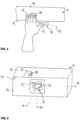
- the fingerprint sensor 5 can also be assigned to a storage area 17 on which the index and/or middle finger and/or ring finger and/or little finger of the hand can be placed, with said storage area 17 e.g. can be contoured in the form of a slight trough in order to guide the hand intuitively into the correct position.
- the storage area 17 can also be assigned an input means, for example in the form of an operating button 18, with the aid of which, for example, control commands for the device can be entered.
- Said storage surface 17 is provided on a first side of the device housing, which can form the lying upper side 8 of the device housing section 4 .
- the fingerprint sensor 5, on the other hand, is arranged on a second side of the device housing, which can be inclined, in particular arranged approximately perpendicularly, to the first side of the device housing mentioned.
- the fingerprint sensor 5 can be provided on an upright front side 9 of the device housing section 4 .
- the fingerprint sensor 5 is spaced from the support surface 17 for the fingers transversely to the housing edge 19, which connects the two aforementioned device housing sides, and/or is spaced from the support surface 17 in the longitudinal direction of the housing edge 19 mentioned, in particular in such a way that the thumb 12 Hand whose index to little fingers are intended to rest on the support surface 17 intuitively comes to rest on the fingerprint sensor 5 in a natural posture, cf. figure 4 .
- the fingerprint sensor 5 can advantageously be arranged such that it can be rotated or tilted, as well as for the embodiment according to FIGS Figures 1 to 3 was described.
- the corresponding tilting axes 14 to 15 are in the Figures 4 and 5 also registered.
- the fingerprint sensor 5 with its main axis 13 is correspondingly inclined at an acute angle to the longitudinal axis of the edge 19 of the device housing, as was explained above for the acute-angled inclination relative to the longitudinal axis 11 of the handle. To avoid repetition, reference is made to the previous description.
- the handle 6 is also designed such that its position can be changed, in particular in such a way that the handle 6 can be brought into two different working positions relative to the fingerprint sensor 5 .
- One working position can be used in particular for left-handed operation and the other working position for right-handed operation of the fingerprint sensor 5 .
- the ability to change the position of the handle 6 can in particular have a mirror image or symmetry with respect to the fingerprint sensor 5 , in particular such that the two working positions mentioned are symmetrical with respect to a plane of symmetry 24 passing through the fingerprint sensor 5 .
- the handle 6 can have a first working position in which at least a larger part of the handle 6 is on a right side of the fingerprint sensor 5, while in a second working position an at least larger part of the handle 6 is on a left side of the fingerprint sensor lies.
- the handle 6 can be pivoted like this figure 6 shows, wherein the handle can have a pivot axis perpendicular to the longitudinal direction of the handle 6, which can extend approximately centrally with respect to the fingerprint sensor 5, for example, can be arranged centrally above said fingerprint sensor 5.
- the handle 6 can also be movable or variable in position in another way, for example by reconnecting between two or more working positions, and/or by the handle 6 being displaceable, for example in the form of a displaceable Storage of the handle 6 parallel to its longitudinal axis. If you look at figure 6 , the handle 6 could also be moved in the longitudinal direction from the right-handed working position shown in solid lines to the left-handed working position shown in dashed lines.
- the handle 6 In its working positions, the handle 6 is positioned relative to the fingerprint sensor 5 in such a way that the thumb of the right or left hand can be positioned on the fingerprint sensor 5 in the manner mentioned.
- the fingerprint sensor 5 can be mounted such that it can be rotated or tilted in a suitable manner, as has already been described in principle.
- the handle 6 can be arranged not only directly on the device housing 2 of the main device 1 or the gaming machine, but also on a device housing section 4 of a control device that is separate from the main device and has an interface 22 so that it can be connected to the main device 1 can.
- This interface 22 can be a wired parallel or serial interface, for example in the form of a USB interface or RS-232 interface, or a wireless interface, for example in the form of a WLAN interface or Bluetooth or IrDA working on the basis of infrared signals interface or a combination of these interfaces.
- the handle 6 can also be designed in several parts, for example in order to be able to assume a parking position or non-operating position in addition to the two working positions figure 9 is shown.
- the handle 6 can comprise a handle element 6a, which forms the actual handle on which the ball of the hand rests and which can be gripped by the fingers of one hand, wherein said handle element can be embodied, for example, as an elongate or rod-shaped element.
- Said handle element 6 can be supported on a support member 6b, which support member 6b can be movably mounted on the device housing section 4.
- said support member 6b of the handle 6 can be pivoted about a pivot axis 23 which extends perpendicularly to the longitudinal direction of the support member 6b.
- the handle element 6a of the handle 6 can in turn be pivoted to said support member 6b, wherein the pivot axis 21 of the handle element 6a can again extend perpendicularly to the longitudinal direction of said handle element.
- Said support member 6b forms, so to speak, a link for the articulated articulation of the handle element 6a on the device housing section 4, which can be part of the device housing of the main device or of a separate operating device.
- the mobility of the handle 6 can be designed in such a way that the handle 6 can be brought into a parking position in which the handle 6, preferably including its grip element 6a and its support member 6b, nestles against the device housing section 4 or is adjacent to this housing section extends along it and is tidied up to save space, so to speak.
- the support member 6b In order to bring the handle 6 into its working position, the support member 6b is erected or positioned so that it cantilevers (e.g. vertically) from the device housing section 4 and, if necessary, is fixed, for example by a detachable plug-in form-fit connection or screw clamp connection or a self-locking snap-in connection.
- the grip element 6a can be angled towards the support member 6b, with the two different working positions, i.e. a first working position in which an at least larger part of the grip element 6a lies on a right-hand side of the fingerprint sensor 5, while in a second working position an at least larger Part of the grip element 6a is on a left side of the fingerprint sensor 5 can be adjusted.
- the fingerprint sensor 5 can advantageously be arranged on said support member 6b and thus on the handle 6, the arrangement in turn being made such that when the index, middle, ring and/or little fingers grip around the handle element 6a Hand the thumb of this hand next to the handle element 6a on the fingerprint sensor 5 can be placed.
- the gripping element 6a of the handle 6 can be brought into two different working positions relative to the support member 6b and thus to the fingerprint sensor 5 in order to optionally grip the handle 6 with the left hand or the right hand and operate the fingerprint sensor 5 to be able to
- Pivotability shown can also be provided in a different way with a multi-part design of the handle 6 a position variability, for example by reconnecting or moving.
- the grip element 6a can be plugged onto the support member 6b in different positions and the support member 6b can be fixed in different positions from the device housing section 4 .
Landscapes
- Engineering & Computer Science (AREA)
- Physics & Mathematics (AREA)
- General Physics & Mathematics (AREA)
- Human Computer Interaction (AREA)
- Multimedia (AREA)
- Theoretical Computer Science (AREA)
- Computer Security & Cryptography (AREA)
- General Engineering & Computer Science (AREA)
- Business, Economics & Management (AREA)
- General Business, Economics & Management (AREA)
- Chemical & Material Sciences (AREA)
- Analytical Chemistry (AREA)
- Software Systems (AREA)
- Signal Processing (AREA)
- Image Input (AREA)
- Measurement Of The Respiration, Hearing Ability, Form, And Blood Characteristics Of Living Organisms (AREA)
- Measurement Of Length, Angles, Or The Like Using Electric Or Magnetic Means (AREA)
- Collating Specific Patterns (AREA)
- User Interface Of Digital Computer (AREA)
Claims (15)
- Appareil équipé d'un capteur d'empreinte digitale (5), dans lequel le capteur d'empreinte digitale (5) est disposé à distance d'une poignée (6) de l'appareil, au voisinage de la poignée (6), de telle sorte que, lorsque l'on passe l'index, et/ou le majeur, et/ou l'annulaire et/ou l'auriculaire d'une main (20) autour de la poignée (6), le pouce (12) de cette main (20) peut être posé sur le capteur d'empreinte digitale (5) à côté de la poignée (6), de sorte qu'un axe longitudinal de pointe de pouce du pouce (12) coïncide sensiblement avec un axe principal (13) du capteur d'empreinte digitale (5), caractérisé en ce que la poignée (6) peut changer de position par rapport au capteur d'empreinte digitale (5) et peut être amenée dans deux positions de travail, dont une position de travail est prévue pour une utilisation de la main gauche du capteur d'empreinte digitale (5) et une autre position de travail pour une utilisation de la main droite du capteur d'empreinte digitale (5), et en ce que le capteur d'empreinte digitale (5) est logé de manière à pouvoir tourner ou basculer.
- Appareil selon la revendication 1, dans lequel le capteur d'empreinte digitale (5) est décalé transversalement par rapport à un axe longitudinal de poignée (11) de la poignée (6) et/ou est disposé à distance dans la direction de l'axe longitudinal de poignée (11) de la poignée (6) et/ou d'une section de préhension de la poignée (6).
- Appareil selon la revendication 1 ou 2, dans lequel le capteur d'empreinte digitale (5) est logé de manière à pouvoir être déplacé en translation par rapport à la poignée (6).
- Appareil selon l'une des revendications 1 à 3, dans lequel le capteur d'empreinte digitale (5) peut être basculé autour d'un axe de basculement (14) qui s'étend approximativement perpendiculairement à une surface d'appui (21) du capteur d'empreinte digitale (5) et/ou approximativement perpendiculairement à un côté de boîtier adjacent au capteur d'empreinte digitale (5), et/ou autour d'un axe de basculement vertical (15) et/ou autour d'un axe de basculement horizontal (16) qui s'étend approximativement parallèlement à la surface d'appui du capteur d'empreinte digitale (5).
- Appareil selon l'une des revendications 1 à 4, dans lequel le capteur d'empreinte digitale (5) peut être amené avec l'axe principal (13) du capteur d'empreinte digitale (5) dans une orientation inclinée à angle aigu par rapport à l'axe longitudinal de poignée (11).
- Appareil selon la revendication 5, dans lequel le capteur d'empreinte digitale (5) peut être amené avec son axe principal (13) dans une orientation basculée à angle aigu sur deux axes par rapport à la poignée (6) et/ou dans une orientation inclinée angulaire par rapport à la poignée (6).
- Appareil selon l'une des revendications 1 à 6, dans lequel la poignée (6) est orientée horizontalement et le capteur d'empreinte digitale (5) est disposé en dessous de la poignée (6).
- Appareil selon l'une des revendications 1 à 7, dans lequel le capteur d'empreinte digitale (5) possède une surface d'appui (21) orientée verticalement.
- Appareil selon l'une des revendications 1 à 8, dans lequel une surface d'appui du capteur d'empreinte digitale (5) se trouve dans un plan ou épouse un plan, lequel plan est incliné à un angle aigu par rapport à l'axe longitudinal de poignée (11).
- Appareil selon l'une des revendications 1 à 9, dans lequel la poignée (6) est logée mobile en va-et-vient entre les deux positions de travail, et les deux positions de travail sont disposées symétriquement par rapport à un plan de symétrie (24) et/ou un axe de symétrie passant par le capteur d'empreinte digitale (5).
- Appareil selon l'une des revendications 1 à 10, dans lequel la poignée (6) est logée mobile entre au moins l'une des deux positions de travail et une position de stationnement et/ou de non-fonctionnement.
- Appareil selon l'une des revendications 1 à 11, dans lequel la poignée (6) est logée pivotante autour d'au moins un axe de pivotement (21), lequel axe de pivotement (21) s'étend de préférence sur une section d'extrémité de la poignée (6) perpendiculairement à la direction longitudinale de la poignée (6).
- Appareil selon l'une des revendications 1 à 12, dans lequel la poignée (6) est formée de plusieurs éléments et comprend des parties de poignée dont la position peut être modifiée les unes par rapport aux autres, le capteur d'empreinte digitale (5) étant monté sur l'une des parties de poignée (6b).
- Appareil selon la revendication 13, dans lequel la poignée (6) présente un élément de poignée (6a) pivotant sur plusieurs axes, qui peut pivoter par rapport à au moins un élément de support (6b) de la poignée (6) autour d'un axe de pivotement (21), lequel élément de support (6b) est lui-même logé pivotant autour d'un axe de pivotement (23) par rapport à la section de boîtier d'appareil (4).
- Appareil selon l'une des revendications 1 à 14, dans lequel l'appareil est formé comme un appareil de commande séparé d'un appareil principal, lequel appareil de commande possède une interface pour la connexion avec l'appareil principal.
Applications Claiming Priority (3)
| Application Number | Priority Date | Filing Date | Title |
|---|---|---|---|
| AT503002014 | 2014-04-23 | ||
| DE102014008160.5A DE102014008160A1 (de) | 2014-05-30 | 2014-05-30 | Gerät mit Fingerabdruck-Sensor |
| PCT/EP2015/058783 WO2015162203A1 (fr) | 2014-04-23 | 2015-04-23 | Appareil équipé d'un capteur d'empreinte digitale |
Publications (3)
| Publication Number | Publication Date |
|---|---|
| EP3134876A1 EP3134876A1 (fr) | 2017-03-01 |
| EP3134876B1 true EP3134876B1 (fr) | 2023-06-07 |
| EP3134876C0 EP3134876C0 (fr) | 2023-06-07 |
Family
ID=53051807
Family Applications (2)
| Application Number | Title | Priority Date | Filing Date |
|---|---|---|---|
| EP15720296.1A Active EP3134846B1 (fr) | 2014-04-23 | 2015-04-22 | Système et procédé d'identification d'empreintes digitales |
| EP15720644.2A Active EP3134876B1 (fr) | 2014-04-23 | 2015-04-23 | Appareil équipé d'un capteur d'empreinte digitale |
Family Applications Before (1)
| Application Number | Title | Priority Date | Filing Date |
|---|---|---|---|
| EP15720296.1A Active EP3134846B1 (fr) | 2014-04-23 | 2015-04-22 | Système et procédé d'identification d'empreintes digitales |
Country Status (12)
| Country | Link |
|---|---|
| US (2) | US10223569B2 (fr) |
| EP (2) | EP3134846B1 (fr) |
| KR (1) | KR102222169B1 (fr) |
| CN (2) | CN106462741B (fr) |
| AU (2) | AU2015250829B2 (fr) |
| CA (2) | CA2946668C (fr) |
| CL (2) | CL2016002696A1 (fr) |
| MX (2) | MX360985B (fr) |
| PH (2) | PH12016502108B1 (fr) |
| RU (2) | RU2683622C2 (fr) |
| WO (2) | WO2015162189A1 (fr) |
| ZA (2) | ZA201607536B (fr) |
Families Citing this family (19)
| Publication number | Priority date | Publication date | Assignee | Title |
|---|---|---|---|---|
| RU2683622C2 (ru) | 2014-04-23 | 2019-03-29 | Новоматик Аг | Приспособление и способ для идентификации отпечатков пальцев |
| TWI647584B (zh) | 2016-04-12 | 2019-01-11 | 速博思股份有限公司 | 手持裝置的操作權限啟用/停用方法 |
| GB2552131A (en) * | 2016-05-06 | 2018-01-17 | Zwipe As | Electrical validation of a purported finger |
| WO2017191328A1 (fr) * | 2016-05-06 | 2017-11-09 | Zwipe As | Validation électrique d'un doigt prétendu |
| CN107437014B (zh) * | 2016-05-27 | 2022-08-26 | 富泰华工业(深圳)有限公司 | 具有指纹识别功能的电子装置及指纹识别方法 |
| TWM542219U (zh) * | 2016-12-01 | 2017-05-21 | 勁永國際股份有限公司 | 指紋隨身碟 |
| US11962702B2 (en) * | 2017-02-24 | 2024-04-16 | REAL IZvest llc | Biometric sensor |
| US10169631B2 (en) | 2017-03-06 | 2019-01-01 | International Business Machines Corporation | Recognizing fingerprints and fingerprint combinations as inputs |
| CN108847586A (zh) * | 2017-07-09 | 2018-11-20 | 杭州力谱科技有限公司 | 一种户外防雨开关柜 |
| CN107633218B (zh) * | 2017-09-08 | 2021-06-08 | 百度在线网络技术(北京)有限公司 | 用于生成图像的方法和装置 |
| SE1751355A1 (en) * | 2017-10-31 | 2019-05-01 | Fingerprint Cards Ab | Method of controlling an electronic device |
| CN108376250B (zh) * | 2018-02-26 | 2020-06-02 | 京东方科技集团股份有限公司 | 一种指纹识别器件及其制备方法、触控面板 |
| FR3095062B1 (fr) * | 2019-04-12 | 2021-03-19 | Idemia Identity & Security France | Carte à puce comportant un capteur d’empreintes digitales |
| CN110278305B (zh) * | 2019-06-29 | 2021-05-04 | Oppo广东移动通信有限公司 | 模式识别方法及相关产品 |
| KR102728412B1 (ko) * | 2019-10-02 | 2024-11-08 | 효성티앤에스 주식회사 | 금융자동화기기 |
| RU2750859C1 (ru) * | 2020-05-14 | 2021-07-05 | Виктор Борисович Наумов | Способ многофакторной динамической идентификации |
| US11802426B1 (en) * | 2022-04-20 | 2023-10-31 | Woven By Toyota, U.S., Inc. | Systems and methods for an identification panel to measure hand static and/or dynamic characteristics |
| FR3137480B1 (fr) * | 2022-06-30 | 2024-10-25 | Banks And Acquirers Int Holding | Dispositif de captation de données biométrique multifonctions et terminal correspondant |
| WO2026024232A1 (fr) * | 2024-07-24 | 2026-01-29 | Secur Solutions Group Pte. Ltd. | Systèmes et appareil d'inscription et d'authentification biométriques |
Citations (1)
| Publication number | Priority date | Publication date | Assignee | Title |
|---|---|---|---|---|
| US20020081005A1 (en) * | 1999-09-17 | 2002-06-27 | Black Gerald R. | Data security system |
Family Cites Families (50)
| Publication number | Priority date | Publication date | Assignee | Title |
|---|---|---|---|---|
| US4467545A (en) * | 1982-08-12 | 1984-08-28 | Shaw Jr Frederic A | Personalized safety method and apparatus for a hand held weapon |
| US5729334A (en) * | 1992-03-10 | 1998-03-17 | Van Ruyven; Lodewijk Johan | Fraud-proof identification system |
| US5546471A (en) * | 1994-10-28 | 1996-08-13 | The National Registry, Inc. | Ergonomic fingerprint reader apparatus |
| US5812252A (en) * | 1995-01-31 | 1998-09-22 | Arete Associates | Fingerprint--Acquisition apparatus for access control; personal weapon and other systems controlled thereby |
| HU214533B (hu) | 1995-10-06 | 1998-03-30 | Dermo Corporation Ltd. | Detektor ujj élő jellegének felismerésére |
| US6100811A (en) * | 1997-12-22 | 2000-08-08 | Trw Inc. | Fingerprint actuation of customized vehicle features |
| AU5341398A (en) | 1997-12-26 | 1999-07-19 | Enix Corporation | Lock and switch using pressure-type fingerprint sensor |
| EA001521B1 (ru) * | 1997-12-26 | 2001-04-23 | Эникс Корпорейшн | Замок и выключатель, в которых используются датчики давления для распознавания отпечатка пальца |
| US6980672B2 (en) * | 1997-12-26 | 2005-12-27 | Enix Corporation | Lock and switch using pressure-type fingerprint sensor |
| US6307956B1 (en) * | 1998-04-07 | 2001-10-23 | Gerald R. Black | Writing implement for identity verification system |
| DE19830830C2 (de) | 1998-07-09 | 2000-11-23 | Siemens Ag | Verfahren zur Lebenderkennung menschlicher Haut |
| US6260300B1 (en) * | 1999-04-21 | 2001-07-17 | Smith & Wesson Corp. | Biometrically activated lock and enablement system |
| KR200169069Y1 (ko) * | 1999-08-20 | 2000-02-15 | 금양전자산업주식회사 | 지문인식 도어록손잡이 |
| DE19944140A1 (de) | 1999-09-15 | 2001-03-29 | Schulze Loewen Automaten | Geldbetätigtes Gerät |
| CN2462476Y (zh) * | 2000-12-27 | 2001-11-28 | 昆明昆船信息产业有限公司 | 指纹键盘 |
| KR200243685Y1 (ko) | 2001-05-19 | 2001-10-29 | 주식회사 케이코하이텍 | 지문인식 기능을 갖는 도어록 손잡이 |
| US6544124B2 (en) * | 2001-08-29 | 2003-04-08 | Radica China Ltd. | Handheld steering wheel game controller |
| JP2003108949A (ja) | 2001-09-28 | 2003-04-11 | Rohm Co Ltd | 認証システム及び半導体装置 |
| CN2522547Y (zh) * | 2001-12-24 | 2002-11-27 | 张七利 | 指纹防盗门锁 |
| WO2003063054A2 (fr) * | 2002-01-17 | 2003-07-31 | Cross Match Technologies, Inc. | Station de travail pour empreintes digitales et procedes |
| DE10232634A1 (de) * | 2002-07-18 | 2004-02-05 | Heckler & Koch Gmbh | Waffe mit elektronischer Waffensicherung |
| KR20040079845A (ko) * | 2003-03-05 | 2004-09-16 | 이주현 | 전류감지를 이용한 지문인식장치 및 그 제조방법 |
| US7113070B2 (en) | 2003-03-21 | 2006-09-26 | Sheng Bill Deng | Door lock and operation mechanism |
| US7161185B2 (en) * | 2003-06-27 | 2007-01-09 | Semiconductor Energy Laboratory Co., Ltd. | Display device and electronic device |
| EP1708135B1 (fr) * | 2004-01-13 | 2011-05-11 | Fujitsu Ltd. | Unite d'authentification utilisant des informations relatives a l'organisme |
| US7539329B2 (en) | 2004-07-01 | 2009-05-26 | Hewlett-Packard Development Company, L.P. | Method and apparatus for enhancing the usability of an electronic device having an integrated fingerprint sensor |
| JP2006077508A (ja) * | 2004-09-10 | 2006-03-23 | Denso Corp | スマートエントリーシステム |
| US7590269B2 (en) * | 2005-04-22 | 2009-09-15 | Microsoft Corporation | Integrated control for navigation, authentication, power on and rotation |
| US7961914B1 (en) * | 2005-07-12 | 2011-06-14 | Smith Robert J D | Portable storage apparatus with integral biometric-based access control system |
| US20070137267A1 (en) | 2005-12-16 | 2007-06-21 | Newfrey Llc | Lock set to deadbolt interlock |
| RU2306393C1 (ru) * | 2005-12-29 | 2007-09-20 | Скробот Владимир Георгиевич | Замок |
| US8628416B2 (en) * | 2007-03-28 | 2014-01-14 | Igt | Device embedded in gaming machine handle |
| US8775238B2 (en) * | 2007-04-03 | 2014-07-08 | International Business Machines Corporation | Generating customized disincentive marketing content for a customer based on customer risk assessment |
| US20100109838A1 (en) | 2008-09-08 | 2010-05-06 | Sherard Fisher | Fingerprint unlocking system |
| EP2364484A4 (fr) * | 2008-11-03 | 2012-05-09 | Cross Match Technologies Inc | Appareil et procédé d'identification de fausses empreintes digitales |
| US20100156594A1 (en) * | 2008-12-19 | 2010-06-24 | Jason Chaikin | Biometric Lock |
| US20100246902A1 (en) * | 2009-02-26 | 2010-09-30 | Lumidigm, Inc. | Method and apparatus to combine biometric sensing and other functionality |
| KR101067189B1 (ko) | 2009-09-07 | 2011-09-22 | 삼성전기주식회사 | 생체인증 장치 |
| US8460099B2 (en) | 2009-10-01 | 2013-06-11 | Wms Gaming, Inc. | Integrating chat and wagering games |
| CN201627408U (zh) * | 2010-02-22 | 2010-11-10 | 浙江圣非格科技有限公司 | 一种可让锁具手柄左右互换的机构 |
| KR101063100B1 (ko) * | 2010-07-06 | 2011-09-07 | 이주협 | 데이터 입력장치 |
| CN101968680B (zh) * | 2010-09-21 | 2012-11-21 | 孟宪超 | 一种无限操控器及其操控方法 |
| US9633247B2 (en) * | 2012-03-01 | 2017-04-25 | Apple Inc. | Electronic device with shared near field communications and sensor structures |
| US20140028439A1 (en) * | 2012-07-27 | 2014-01-30 | Jack Lien | Sensor-embedded door handle with fingerprint identification function |
| US10092669B2 (en) | 2012-08-14 | 2018-10-09 | Strategic Partnerships Alliance, LLC | Sterilizing radiation system for use with door handle |
| US20140196636A1 (en) | 2013-01-16 | 2014-07-17 | Timothy Deweese | Safe weapon container for securely releasing a defense weapon |
| US9441403B2 (en) | 2013-05-15 | 2016-09-13 | Trimark Corporation | Power locking door handles with integrated keypad |
| RU2683622C2 (ru) * | 2014-04-23 | 2019-03-29 | Новоматик Аг | Приспособление и способ для идентификации отпечатков пальцев |
| US20150337571A1 (en) | 2014-04-30 | 2015-11-26 | STRATTEC Advanced Logic | Handle with integrated biometrics and vehicular biometric device |
| US9867513B1 (en) * | 2016-09-06 | 2018-01-16 | David R. Hall | Medical toilet with user authentication |
-
2015
- 2015-04-22 RU RU2016142447A patent/RU2683622C2/ru active
- 2015-04-22 KR KR1020167032272A patent/KR102222169B1/ko active Active
- 2015-04-22 MX MX2016013865A patent/MX360985B/es active IP Right Grant
- 2015-04-22 CN CN201580030549.8A patent/CN106462741B/zh active Active
- 2015-04-22 US US15/305,942 patent/US10223569B2/en active Active
- 2015-04-22 EP EP15720296.1A patent/EP3134846B1/fr active Active
- 2015-04-22 WO PCT/EP2015/058742 patent/WO2015162189A1/fr not_active Ceased
- 2015-04-22 CA CA2946668A patent/CA2946668C/fr active Active
- 2015-04-22 AU AU2015250829A patent/AU2015250829B2/en active Active
- 2015-04-23 CA CA2946673A patent/CA2946673C/fr active Active
- 2015-04-23 WO PCT/EP2015/058783 patent/WO2015162203A1/fr not_active Ceased
- 2015-04-23 AU AU2015250843A patent/AU2015250843B2/en active Active
- 2015-04-23 US US15/305,947 patent/US10074001B2/en active Active
- 2015-04-23 RU RU2016142446A patent/RU2683621C2/ru active
- 2015-04-23 EP EP15720644.2A patent/EP3134876B1/fr active Active
- 2015-04-23 MX MX2016013866A patent/MX360986B/es active IP Right Grant
- 2015-04-23 CN CN201580030557.2A patent/CN106462742B/zh active Active
-
2016
- 2016-10-21 PH PH12016502108A patent/PH12016502108B1/en unknown
- 2016-10-24 CL CL2016002696A patent/CL2016002696A1/es unknown
- 2016-10-24 CL CL2016002697A patent/CL2016002697A1/es unknown
- 2016-10-24 PH PH12016502127A patent/PH12016502127B1/en unknown
- 2016-11-01 ZA ZA2016/07536A patent/ZA201607536B/en unknown
- 2016-11-01 ZA ZA2016/07537A patent/ZA201607537B/en unknown
Patent Citations (1)
| Publication number | Priority date | Publication date | Assignee | Title |
|---|---|---|---|---|
| US20020081005A1 (en) * | 1999-09-17 | 2002-06-27 | Black Gerald R. | Data security system |
Also Published As
Similar Documents
| Publication | Publication Date | Title |
|---|---|---|
| EP3134876B1 (fr) | Appareil équipé d'un capteur d'empreinte digitale | |
| EP0840910B1 (fr) | Appareil de programmation | |
| DE69425608T2 (de) | Tragbarer Rechner mit Tastatur oder Stift zur Dateneingabe | |
| EP2186068B1 (fr) | Appareil de jeu électronique | |
| DE20214045U1 (de) | Maus für Computer mit ergonomisch geformten und platzierten Tasten | |
| WO2014108141A1 (fr) | Appareil électronique de jeu et/ou divertissement | |
| DE102018117790A1 (de) | Maschinenbedienpanel mit integriertem Bedienterminal, und externes Gerät | |
| CH707230A2 (de) | Türsystem mit berührungsloser Zutrittskontrolle und berührungsloser Türbedienung. | |
| DE60105896T2 (de) | Druckereinheit für Transaktionsvorrichtung | |
| EP0845133B1 (fr) | Caisse enregistreuse | |
| EP3931806B1 (fr) | Machine à sous en forme de siège | |
| WO2015180998A1 (fr) | Appareil pourvu d'un élément de commande associé à une poignée | |
| DE102014008160A1 (de) | Gerät mit Fingerabdruck-Sensor | |
| DE202017105701U1 (de) | Funkfernsteuergerät zur Funkfernsteuerung einer Maschine, insbesondere eines Kranes | |
| EP2110200B1 (fr) | Emplacement d'utilisation libre destiné à la commande d'un centre de traitement | |
| DE19834699B4 (de) | Vorrichtung zur Steuerung von Datenverarbeitungsgeräten | |
| DE29919297U1 (de) | Handauflage mit integrierter Maus | |
| DE29511863U1 (de) | Programmiergerät mit Steuerorgan | |
| DE3611240C2 (fr) | ||
| DE8709863U1 (de) | Steuerteil für Computerspiele | |
| DE20022794U1 (de) | Mobiltelefon | |
| DE202010007673U1 (de) | Datenverarbeitungsvorrichtungeingabeeinheiten | |
| EP2474285A1 (fr) | Dispositif de conservation de spatules médicales | |
| DE7509268U (de) | Kassenbox fuer geldinstitute | |
| DE29619928U1 (de) | Ergonomische Computertastatur |
Legal Events
| Date | Code | Title | Description |
|---|---|---|---|
| STAA | Information on the status of an ep patent application or granted ep patent |
Free format text: STATUS: THE INTERNATIONAL PUBLICATION HAS BEEN MADE |
|
| PUAI | Public reference made under article 153(3) epc to a published international application that has entered the european phase |
Free format text: ORIGINAL CODE: 0009012 |
|
| STAA | Information on the status of an ep patent application or granted ep patent |
Free format text: STATUS: REQUEST FOR EXAMINATION WAS MADE |
|
| 17P | Request for examination filed |
Effective date: 20161121 |
|
| AK | Designated contracting states |
Kind code of ref document: A1 Designated state(s): AL AT BE BG CH CY CZ DE DK EE ES FI FR GB GR HR HU IE IS IT LI LT LU LV MC MK MT NL NO PL PT RO RS SE SI SK SM TR |
|
| AX | Request for extension of the european patent |
Extension state: BA ME |
|
| DAV | Request for validation of the european patent (deleted) | ||
| DAX | Request for extension of the european patent (deleted) | ||
| STAA | Information on the status of an ep patent application or granted ep patent |
Free format text: STATUS: EXAMINATION IS IN PROGRESS |
|
| 17Q | First examination report despatched |
Effective date: 20190411 |
|
| REG | Reference to a national code |
Ref country code: DE Ref legal event code: R079 Ref document number: 502015016394 Country of ref document: DE Free format text: PREVIOUS MAIN CLASS: G07C0009000000 Ipc: G07F0017320000 |
|
| RIC1 | Information provided on ipc code assigned before grant |
Ipc: G06V 40/12 20220101ALI20220810BHEP Ipc: G07C 9/37 20200101ALI20220810BHEP Ipc: G07F 17/32 20060101AFI20220810BHEP |
|
| GRAP | Despatch of communication of intention to grant a patent |
Free format text: ORIGINAL CODE: EPIDOSNIGR1 |
|
| STAA | Information on the status of an ep patent application or granted ep patent |
Free format text: STATUS: GRANT OF PATENT IS INTENDED |
|
| INTG | Intention to grant announced |
Effective date: 20220929 |
|
| GRAS | Grant fee paid |
Free format text: ORIGINAL CODE: EPIDOSNIGR3 |
|
| GRAA | (expected) grant |
Free format text: ORIGINAL CODE: 0009210 |
|
| STAA | Information on the status of an ep patent application or granted ep patent |
Free format text: STATUS: THE PATENT HAS BEEN GRANTED |
|
| AK | Designated contracting states |
Kind code of ref document: B1 Designated state(s): AL AT BE BG CH CY CZ DE DK EE ES FI FR GB GR HR HU IE IS IT LI LT LU LV MC MK MT NL NO PL PT RO RS SE SI SK SM TR |
|
| REG | Reference to a national code |
Ref country code: GB Ref legal event code: FG4D Free format text: NOT ENGLISH |
|
| REG | Reference to a national code |
Ref country code: CH Ref legal event code: EP Ref country code: AT Ref legal event code: REF Ref document number: 1577328 Country of ref document: AT Kind code of ref document: T Effective date: 20230615 |
|
| REG | Reference to a national code |
Ref country code: DE Ref legal event code: R096 Ref document number: 502015016394 Country of ref document: DE |
|
| U01 | Request for unitary effect filed |
Effective date: 20230703 |
|
| U07 | Unitary effect registered |
Designated state(s): AT BE BG DE DK EE FI FR IT LT LU LV MT NL PT SE SI Effective date: 20230710 |
|
| REG | Reference to a national code |
Ref country code: LT Ref legal event code: MG9D |
|
| PG25 | Lapsed in a contracting state [announced via postgrant information from national office to epo] |
Ref country code: NO Free format text: LAPSE BECAUSE OF FAILURE TO SUBMIT A TRANSLATION OF THE DESCRIPTION OR TO PAY THE FEE WITHIN THE PRESCRIBED TIME-LIMIT Effective date: 20230907 Ref country code: ES Free format text: LAPSE BECAUSE OF FAILURE TO SUBMIT A TRANSLATION OF THE DESCRIPTION OR TO PAY THE FEE WITHIN THE PRESCRIBED TIME-LIMIT Effective date: 20230607 |
|
| PG25 | Lapsed in a contracting state [announced via postgrant information from national office to epo] |
Ref country code: RS Free format text: LAPSE BECAUSE OF FAILURE TO SUBMIT A TRANSLATION OF THE DESCRIPTION OR TO PAY THE FEE WITHIN THE PRESCRIBED TIME-LIMIT Effective date: 20230607 Ref country code: HR Free format text: LAPSE BECAUSE OF FAILURE TO SUBMIT A TRANSLATION OF THE DESCRIPTION OR TO PAY THE FEE WITHIN THE PRESCRIBED TIME-LIMIT Effective date: 20230607 Ref country code: GR Free format text: LAPSE BECAUSE OF FAILURE TO SUBMIT A TRANSLATION OF THE DESCRIPTION OR TO PAY THE FEE WITHIN THE PRESCRIBED TIME-LIMIT Effective date: 20230908 |
|
| PG25 | Lapsed in a contracting state [announced via postgrant information from national office to epo] |
Ref country code: SK Free format text: LAPSE BECAUSE OF FAILURE TO SUBMIT A TRANSLATION OF THE DESCRIPTION OR TO PAY THE FEE WITHIN THE PRESCRIBED TIME-LIMIT Effective date: 20230607 |
|
| PG25 | Lapsed in a contracting state [announced via postgrant information from national office to epo] |
Ref country code: IS Free format text: LAPSE BECAUSE OF FAILURE TO SUBMIT A TRANSLATION OF THE DESCRIPTION OR TO PAY THE FEE WITHIN THE PRESCRIBED TIME-LIMIT Effective date: 20231007 |
|
| PG25 | Lapsed in a contracting state [announced via postgrant information from national office to epo] |
Ref country code: SM Free format text: LAPSE BECAUSE OF FAILURE TO SUBMIT A TRANSLATION OF THE DESCRIPTION OR TO PAY THE FEE WITHIN THE PRESCRIBED TIME-LIMIT Effective date: 20230607 Ref country code: SK Free format text: LAPSE BECAUSE OF FAILURE TO SUBMIT A TRANSLATION OF THE DESCRIPTION OR TO PAY THE FEE WITHIN THE PRESCRIBED TIME-LIMIT Effective date: 20230607 Ref country code: RO Free format text: LAPSE BECAUSE OF FAILURE TO SUBMIT A TRANSLATION OF THE DESCRIPTION OR TO PAY THE FEE WITHIN THE PRESCRIBED TIME-LIMIT Effective date: 20230607 Ref country code: IS Free format text: LAPSE BECAUSE OF FAILURE TO SUBMIT A TRANSLATION OF THE DESCRIPTION OR TO PAY THE FEE WITHIN THE PRESCRIBED TIME-LIMIT Effective date: 20231007 Ref country code: CZ Free format text: LAPSE BECAUSE OF FAILURE TO SUBMIT A TRANSLATION OF THE DESCRIPTION OR TO PAY THE FEE WITHIN THE PRESCRIBED TIME-LIMIT Effective date: 20230607 |
|
| PG25 | Lapsed in a contracting state [announced via postgrant information from national office to epo] |
Ref country code: PL Free format text: LAPSE BECAUSE OF FAILURE TO SUBMIT A TRANSLATION OF THE DESCRIPTION OR TO PAY THE FEE WITHIN THE PRESCRIBED TIME-LIMIT Effective date: 20230607 |
|
| REG | Reference to a national code |
Ref country code: DE Ref legal event code: R097 Ref document number: 502015016394 Country of ref document: DE |
|
| PLBE | No opposition filed within time limit |
Free format text: ORIGINAL CODE: 0009261 |
|
| STAA | Information on the status of an ep patent application or granted ep patent |
Free format text: STATUS: NO OPPOSITION FILED WITHIN TIME LIMIT |
|
| 26N | No opposition filed |
Effective date: 20240308 |
|
| U20 | Renewal fee for the european patent with unitary effect paid |
Year of fee payment: 10 Effective date: 20240417 |
|
| PG25 | Lapsed in a contracting state [announced via postgrant information from national office to epo] |
Ref country code: MC Free format text: LAPSE BECAUSE OF FAILURE TO SUBMIT A TRANSLATION OF THE DESCRIPTION OR TO PAY THE FEE WITHIN THE PRESCRIBED TIME-LIMIT Effective date: 20230607 |
|
| PG25 | Lapsed in a contracting state [announced via postgrant information from national office to epo] |
Ref country code: MC Free format text: LAPSE BECAUSE OF FAILURE TO SUBMIT A TRANSLATION OF THE DESCRIPTION OR TO PAY THE FEE WITHIN THE PRESCRIBED TIME-LIMIT Effective date: 20230607 |
|
| REG | Reference to a national code |
Ref country code: CH Ref legal event code: PL |
|
| PG25 | Lapsed in a contracting state [announced via postgrant information from national office to epo] |
Ref country code: CH Free format text: LAPSE BECAUSE OF NON-PAYMENT OF DUE FEES Effective date: 20240430 |
|
| PG25 | Lapsed in a contracting state [announced via postgrant information from national office to epo] |
Ref country code: IE Free format text: LAPSE BECAUSE OF NON-PAYMENT OF DUE FEES Effective date: 20240423 |
|
| U20 | Renewal fee for the european patent with unitary effect paid |
Year of fee payment: 11 Effective date: 20250424 |
|
| PG25 | Lapsed in a contracting state [announced via postgrant information from national office to epo] |
Ref country code: CY Free format text: LAPSE BECAUSE OF FAILURE TO SUBMIT A TRANSLATION OF THE DESCRIPTION OR TO PAY THE FEE WITHIN THE PRESCRIBED TIME-LIMIT; INVALID AB INITIO Effective date: 20150423 |
|
| PG25 | Lapsed in a contracting state [announced via postgrant information from national office to epo] |
Ref country code: HU Free format text: LAPSE BECAUSE OF FAILURE TO SUBMIT A TRANSLATION OF THE DESCRIPTION OR TO PAY THE FEE WITHIN THE PRESCRIBED TIME-LIMIT; INVALID AB INITIO Effective date: 20150423 |
|
| PGFP | Annual fee paid to national office [announced via postgrant information from national office to epo] |
Ref country code: GB Payment date: 20260324 Year of fee payment: 12 |