EP3135126B1 - Verbesserungen an einer entsaftermaschine - Google Patents
Verbesserungen an einer entsaftermaschine Download PDFInfo
- Publication number
- EP3135126B1 EP3135126B1 EP15782960.7A EP15782960A EP3135126B1 EP 3135126 B1 EP3135126 B1 EP 3135126B1 EP 15782960 A EP15782960 A EP 15782960A EP 3135126 B1 EP3135126 B1 EP 3135126B1
- Authority
- EP
- European Patent Office
- Prior art keywords
- fruit
- machine
- peeler
- juice extraction
- rack
- Prior art date
- Legal status (The legal status is an assumption and is not a legal conclusion. Google has not performed a legal analysis and makes no representation as to the accuracy of the status listed.)
- Active
Links
Images







Classifications
-
- A—HUMAN NECESSITIES
- A23—FOODS OR FOODSTUFFS; TREATMENT THEREOF, NOT COVERED BY OTHER CLASSES
- A23N—MACHINES OR APPARATUS FOR TREATING HARVESTED FRUIT, VEGETABLES OR FLOWER BULBS IN BULK, NOT OTHERWISE PROVIDED FOR; PEELING VEGETABLES OR FRUIT IN BULK; APPARATUS FOR PREPARING ANIMAL FEEDING- STUFFS
- A23N1/00—Machines or apparatus for extracting juice
- A23N1/02—Machines or apparatus for extracting juice combined with disintegrating or cutting
-
- A—HUMAN NECESSITIES
- A23—FOODS OR FOODSTUFFS; TREATMENT THEREOF, NOT COVERED BY OTHER CLASSES
- A23N—MACHINES OR APPARATUS FOR TREATING HARVESTED FRUIT, VEGETABLES OR FLOWER BULBS IN BULK, NOT OTHERWISE PROVIDED FOR; PEELING VEGETABLES OR FRUIT IN BULK; APPARATUS FOR PREPARING ANIMAL FEEDING- STUFFS
- A23N1/00—Machines or apparatus for extracting juice
Definitions
- This application requests a Patent of Invention for improvements to a juice extraction machine, particularly an extremely compact commercial-scale fruit juice extraction machine, capable of being handled and transported very easily and which stands out for a differentiated constructive configuration that, among other items, for using a tilting basket at the front that, when completely closed, keeps its side walls close to the peeler cups and, when opened, facilitates the removal of peel and bagasse wastes.
- the invention also stands out for having arranged on the mobile peeler and connect thereto a fruit-rack, intended for receiving the fruit during the second stage (when the fruit is on the mobile peeler) with this rack having a smooth and slightly curved surface (with a broad radius), serving as a waiting stage for the fruit (before it falls in the peelers) without damaging the fruit and ensuring that it slides easily, in addition to significantly enhancing the efficiency of the machine, which is small compared to others, although highly productive.
- a machine developed for processing citrus fruit in general with no manual contact comprised of a tubular chassis attached to an extraction compartment in which is installed the geared motor actuating a crankshaft that in turn axially displaces a peeler cup against another peeler cup in order to press the fruit released by a trigger located on a mouth of a fruit tray, there being a central shaft in one of the above-mentioned peeler cups and a perforation tube for juice extraction in the other, such that all solid wastes are discharged into a basket while the liquid runs through a filter, flowing sequentially through a tube in a horizontal "S" shape.
- N° MU7501780-6 for the machine's feeding system, describing the steady supply into the machine in a synchronized manner through a feeding arm positioned transversely in the feeding mouth, preventing the fruit from passing, and as the mobile peeler cup moves towards the static, i.e fixed, peeler cup, there is a displacement of said arm allowing a fruit to fall into the container, and so on successively, such that, in each cycle a fruit falls directly into the peelers.
- the second issue to be addressed consists of the so-called second stage of the fruit, which is when it is positioned over the mobile peeler, since, as it is formed by blades its outer shape does not favor the sliding of fruit during linear movement.
- another technical issue noted by the inventor relates to the fruit wastes, which are thrown towards the top part of the machine, as the peeler is hollow.
- the inventor designed a surrounding tilting basket that takes advantage not only of the distance factor but also of its constructive form.
- the walls of the surrounding tilting basket are close to the peelers which, in addition to helping to solve the waste removal, also makes the machine very compact, yet highly productive.
- the side walls of the above-mentioned surrounding tilting basket have semicircular conformations, thus allowing a rotational displacement so that the waste can be very easily removed.
- the inventor introduced a fruit-rack, such rack being positioned on the outer top face of the mobile peeler and having movements consistent with it.
- This fruit-rack also serves as a deflector for waste, not allowing them to fly upwards in order to keep the top part of the machine clean.
- the fruit goes through three stages, all synchronized by the mobile peeler movement.
- the fruit rests on the transverse spring, still inside the feeder;
- the second stage by the contact action of the spring release means during the linear movement of the mobile peeler towards the fixed peeler, the fruit falls on the fruit-rack being kept above the mobile peeler by the action of the transverse spring;
- the third stage the fruit falls between the fixed and mobile peelers, promoting the peeling of the fruit and the extraction of the juice itself almost simultaneously.
- a helical transverse spring is arranged between the feeder tube and the fruit-rack set, which at first retains the fruit present in the (vertical) feeder, or dispenser (first stage), with the activation of this spring being done by means inserted in the above-mentioned fruit-rack set that is actuated by the same axle that moves the mobile peeler, such that the fruit waiting on the rounded fruit-rack constitutes the second stage, wherefrom such fruit will be released into the peeler set only when the fruit movement component (present on the fruit-rack set) touches such fruit during the linear movement, making it fall to the third stage, between the peelers, which is the act of peeling the fruit and extracting the juice simultaneously.
- the helical transverse spring is touched by the spring actuators, releasing the fruit lined up in the feeder to fall on the above-mentioned fruit-rack.
- the fruit going through the dispenser falls on the top part of the mobile peeler and then on the inside of the peeler during the next cycle, when the juice is extracted. Assuming that the dispenser or feeder tube is full, at each cycle there will be one fruit in each of the mentioned stages.
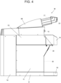
- the improvements to a juice extraction machine addressed by this application for a Patent of Invention are improvements to be implemented in a juice extraction machine (M), comprising a fruit-rack set (1) with arched cross-section and whose movement is synchronized with the drive axle of the mobile peeler (2), said fruit-rack (1) being coupled to the mobile peeler set (2) through fittings (3), including in the machine a transverse spring (4) fixed at the bottom of the feeder/dispenser tube (5), said transverse spring (4) whose means of actuation (51) are provided on the fruit-rack set (1);
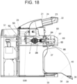
- the improved machine (M) comprises a tilting waste basket (7) in its front side, said tilting waste basket (7) having substantially semi-circular sides (8) close to the mobile (2) and fixed (2B) peelers aligned with each other, with the latter being concatenated with the filter and piston set (67), that is mounted inside the fixed peeler (2B) ( FIGURES 6 , 7 and 18 ).
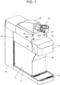
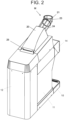
- the machine (M) presents a flat and leveled support base (9) that is rectangular in the version herein presented, that receives, in its bottom front part, a housing for a drip tray (10), in addition to flat vertical side-cowlings (11), rear vertical cowlings (12), top cowlings (13) that form a top front surface (14) for receiving actuation buttons or displays, one of which is an emergency button (15), a general switch (16), an on-switch (17), an off-switch (18), in addition to LED indicator lights (19) for peels and (19B) open ( FIGURES 1 , 2 and 5 ).
- a drip tray (10) in addition to flat vertical side-cowlings (11), rear vertical cowlings (12), top cowlings (13) that form a top front surface (14) for receiving actuation buttons or displays, one of which is an emergency button (15), a general switch (16), an on-switch (17), an off-switch (18), in addition to LED indicator lights (19) for peels and (19B) open ( FIGURE
- a cowling (20) that receives a fruit funnel (21), containing in a front plane a sizer element (22) of the maximum and minimum sizes of fruit, said fruit funnel (21) consisting of a wired element that communicates with the feeder/dispenser (5) inside the machine, with this funnel having an receiving rim (23) and a cylindrical wire conduit (24) projecting towards the inside of the machine, at a slight slant that is sufficient to allow the fruit to move forward through gravity.
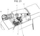
- the electro-electronic part of the machine is a commonplace solution and is not object of this protection, with the components listed for clarification purposes and for allowing a person skilled in the matter to reproduce the product, with a market solution ( FIGURES 1 , 2 , 3 , 6 , 18 , 19 , 20 and 21 ).
- the top cowling (20) has in the rear part thereof an articulation mechanism (25) that moves it into the open or closed position, while internally a metal structure is configured in rectangular sheeting sections (26) that apply to the sides, that are supported on the bottom metal frame (27) of the support base (9), with the latter receiving the sheet metal sections (28), with the rear ones (29) having openings (30) in order to provide a means of ventilation for the gear-motor set (31) that drives the mobile peeler (2) and fruit-rack set (1), while the front section is a solid metal sheet (32) with curved edges (33) attached to the sheet metal structure (26), said solid metal sheet (32) surmounted by a thin metal sheet with front slots (34), above which are the pivot points (35) of the tilting basket (7) whose sides are approximately semicircular (8), with such basket having a free end in flap projected in transversal extension (36) that acts in a spring-pin locking device (37) to keep it latched in the closed position, while the front metal sheet (38) of said basket includes a pulling element (39) made from plastic or
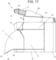
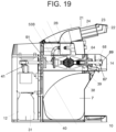
- the front metal sheet (38) has an inverted ramp surface (convex) such that when articulated to the open position the tilting basket (7), forms a ramp surface (40) that allows easier waste cleaning ( FIGURES 10 , 17 , 18 and 19 ).
- gear-motor set (31) In the rear part of the machine is the gear-motor set (31), which is in turn fixed to the base in sheet metal sections affixed to the structure (27) of the metal base (9) and to the structure in rectangular metal sheet sections (26), this fixation being done by means of screws or other conventional means ( FIGURE 6 and 7 ).
- a crank arm (41) Projecting from the top end of the gear-motor set (31) is a crank arm (41) whose pivotable end (42) couples to an axle (43) with a pulley (45) that in turn operates inside a guide (44) in a transverse position to the machine, with such guide (44) receiving, at the opposite ends, the fitting of opposing cylindrical axles (46) passing through the metal sheet side guides (47) and the guide (44) and supported on the front ends (47B) of the structural part of the machine, said metal sheet side guides (47) having recessed rectangular areas (48) where the helical springs (49) with plastic stoppers (50) act, whose extended linear movements are limited by the recessed rectangular areas (48), thus defining the maximum extension of displacement of said plastic stoppers (50), through converting the rotating movement of the crank arm (41) into the linear movement of the guide (44).
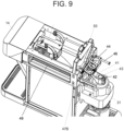
- the opposing parallel axles (51) of the mobile peeler (2) are coupled to the guide (44), said opposing parallel axles (51) being integrally coupled to the guide (44) and passing through the structure of the machine in bushings (52) incorporated into the structural sheet (53), and with such opposing parallel axles (51) extending to the opposite sides of the mobile peeler (2), where they are attached to the diamond-shaped base (53B) in order to endow the latter with alternating linear to-and-fro movements ( FIGURES 8 , 9 , 18 and 19 ).
- Said substantially diamond-shaped base (53B) has opposing vertices along the largest direction of the diamond with holes (54) for the passage of said axles (51); with said base providing vertical housings (55) that receive the fittings (3) of the fruit-rack set (1), with the latter comprising a base/support (56) provided with a concave arch (57) whose radius is larger than that of the fruit (F) that it will receive, with substantially "C"-shaped arms (58) projecting on both opposite sides from the rear part of such fruit-rack, with internal reinforcement elements (59) whose ends are fitted with substantially "U”-shaped supports that receive axles with pulleys (60) for actuating the helical transverse spring (4) for releasing or retaining the fruit (F) during the operating stages of the machine (M) ( FIGURES 11, 12 , 13, 14 and 15 ).
- the substantially "C"-shaped arms (58) with the pulleys (60), adjacent to the mobile peeler set (2) reach the transverse spring (4) that runs through an axial cross-section (4B) of the feeder/dispenser (5), with said transverse spring (4) being supported by the spring supported pulleys (61) parallel and fixed to the sides of the machine casing, releasing the fruit (F) that falls by gravity into the cradle base/support (56);
- said cradle base/support (56) consists of a smooth surface (62) with an elongated cross-section whose center (63) is slightly recessed into a "V"-shape forming an arch (57) such that it prevents damage to the fruit (F) and favors its slipping; on the front part of the smooth surface (62) is a rounded cut-out (63B) whose linear movement either limits the passage of the fruit or releases it into the next stage ( FIGURES 11 , 20 and 21 ).
- the filter (64) arranged on the front part of the machine (M) communicates with the inner part of the fixed peeler (2B) and with the "S"-shaped liquid releasing tube (65) through the actuator (66).
- the fixation of the filter and piston set (67) to the machine (M) is made by a transverse blade (68) affixed to the axles (46) by conventional means and with a front lid (69) capable of being removed when necessary ( FIGURES 6 , 18 and 19 ).
- the fruit (F) goes through three stages, all synchronized by the movement of the mobile peeler (2).
- the fruit (F) rests on the transverse spring (4), still inside the feeder/dispenser (5);
- the fruit (F) falls on the fruit-rack set (1) being kept above the mobile peeler (2) by the action of the transverse spring (4);
- the fruit (F) falls between the fixed (2B) and mobile (2) peelers promoting the extraction of the juice.
Landscapes
- Life Sciences & Earth Sciences (AREA)
- Chemical & Material Sciences (AREA)
- Engineering & Computer Science (AREA)
- Food Science & Technology (AREA)
- Polymers & Plastics (AREA)
- Apparatuses For Bulk Treatment Of Fruits And Vegetables And Apparatuses For Preparing Feeds (AREA)
Claims (12)
- Eine Entsaftermaschine (M), umfassend:eine feststehende Schälvorrichtung (2B) und eine bewegliche Schälvorrichtung (2), die von einer Getriebemotoreinheit (31) mit einem Antriebshebel (41) angetrieben wird, wobei die bewegliche Schälvorrichtung (2) mit der Getriebemotoreinheit (31) verbunden ist;eine Haube (20) mit einem Fruchttrichter (21), der mit einem Zufuhr- und Ausgaberohr (5) in der Maschine verbunden ist;eine bogenförmige Fruchtschiene (1), deren Bewegung mit der Antriebsachse einer beweglichen Schälvorrichtung (2) synchronisiert ist;wobei der Trichter einen Aufnahmekranz (23) und einen zylindrischen Drahtkanal (24) auf einer geneigten Ebene aufweist, um die Früchte durch die Schwerkraft vorwärtszubefördern;wobei das Zufuhr- und Ausgaberohr (5) eine Querfeder (4) umfasst, die am Boden des Zufuhr- und Ausgaberohrs (5) angebracht ist, um die Frucht zurückzuhalten;wobei die Fruchtschiene (1) an einer äußeren Oberseite der mobilen Schälvorrichtung positioniert und so angeordnet ist, dass sie als Wartestufe dient, bevor die Frucht auf die Schälvorrichtungen fällt;wobei die Fruchtschiene (1) durch Verbindungsstücke (3) an der beweglichen Schälvorrichtung (2) befestigt ist; und wobei die Querfeder zwischen dem Zufuhr- und Ausgaberohr und der Fruchtschiene angeordnet ist;wobei eine Einrichtung zur Freigabe der Feder (6) zum Betätigen der an der Fruchtschiene (1) angebrachten Querfeder (4) angebracht ist, um die Frucht aus dem Inneren des Zufuhr- und Ausgaberohrs freizugeben, damit sie durch eine lineare Bewegung der beweglichen Schälvorrichtung in Richtung des feststehenden Schälvorrichtung auf die Fruchtschiene fällt.
- Die Entsaftermaschine nach Anspruch 1, wobei die Fruchtschiene (1) einen Basisträger (56) umfasst, der eine glatte Oberfläche (62) mit einem länglichen Querschnitt umfasst, dessen Mitte (63) leicht zu einer "V"-Form abgesenkt ist, die einen konkaven Bogen (57) bildet; wobei sich am oberen Teil der glatten Oberfläche (62) ein abgerundeter Ausschnitt (63B) befindet.
- Die Entsaftermaschine nach Anspruch 1, wobei die Querfeder (4) eine Querfeder ist, die durch eine axiale Aussparung des Zufuhr- und Ausgaberohrs (5) verläuft.
- Die Entsaftermaschine nach Anspruch 1, wobei die Entsaftermaschine einen kippbaren Abfallbehälter (7) umfasst, der in der Nähe der beweglichen Schälvorrichtung (2) und der feststehenden Schälvorrichtung (2B) angeordnet ist, wobei der kippbare Abfallbehälter (7) halbkreisförmig ausgebildete Seiten (8) aufweist.
- Die Entsaftermaschine nach den Ansprüchen 1 und 4, wobei der kippbare Abfallbehälter (7) eine Klappe aufweist, die von der Querverlängerung (36) vorsteht und in eine Verriegelungsvorrichtung mit Federstift (37) eingreift, um diese in der geschlossenen Position verriegelt zu halten, während ein vorderes Blech (38) des genannten kippbaren Abfallbehälters ein Zugelement (39) aufweist.
- Die Entsaftermaschine nach den Ansprüchen 1 und 5, wobei die Oberfläche des vorderen Blechs (38) eine umgekehrt geneigte Ebene aufweist, die eine Oberfläche einer geneigten Ebene (40) bildet, wenn sich der kippbare Abfallbehälter (7) in der geöffneten Position befindet.
- Die Entsaftermaschine nach Anspruch 1, umfassend eine Getriebemotoreinheit (31) auf der Rückseite der Maschine, die an einer Basis aus Blechprofilen befestigt ist, die an einer Struktur (27) einer Metallbasis (9) und an einer Struktur aus rechteckigen Blechprofilen (26) angebracht sind.
- Die Entsaftermaschine nach den Ansprüchen 1 und 7, umfassend einen Antriebshebel (41), der von einem oberen Ende der Getriebemotoreinheit (31) vorsteht und dessen schwenkbares Ende (42) mit einer Achse (43) mit einer Rolle (45) verbunden ist, die in einer Führung (44) quer zur Maschine arbeitet, wobei diese Führung (44) an den gegenüberliegenden Enden den Sitz der gegenüberliegenden zylindrischen Achsen (46) aufnimmt, die durch die seitlichen Blechführungen (47) und die Führung (44) hindurchgehen und von den vorderen Enden (47b) des strukturellen Teils der Maschine gehalten werden, wobei die seitlichen Blechführungen (47) Bereiche mit rechteckigen Vertiefungen (48) aufweisen, in denen Schraubenfedern (49) mit Kunststoffanschlägen (50) wirken, deren verlängerte lineare Bewegungen durch einen vertieften rechteckigen Bereich (48) begrenzt sind; und mit der Führung (44) der gegenüberliegenden parallelen Achsen (51) der beweglichen Schälvorrichtung (2) gekoppelt sind, wobei die so gegenüberliegenden parallelen Achsen (51) vollständig an der Führung (44) befestigt sind und durch die Struktur der Maschine auf Buchsen (52) laufen, die in ein Strukturblech (53) eingearbeitet sind, wobei sich solche gegenüberliegenden parallelen Achsen (51) zu den gegenüberliegenden Seiten der beweglichen Schälvorrichtung (2) erstrecken, wo sie an einer rautenförmigen Basis (53b) befestigt sind.
- Die Entsaftermaschine nach den Ansprüchen 1 und 8, wobei die rautenförmige Basis (53b) gegenüberliegende Scheitelpunkte entlang der breitesten Richtung der Rautenform mit Öffnungen (54) für den Durchgang der genannten gegenüberliegenden parallelen Achsen (51) aufweist; wobei die genannte Basis vertikale Gehäuse (55) aufweist, die die Verbindungsstücke (3) der Fruchtschiene (1) aufnehmen, wobei letztere einen gebogenen (57) Basisträger (56) mit einem Radius, der größer ist als der Radius der aufzunehmenden Frucht (f) mit im wesentlichen "C"-förmigen Armen (58) aufweist, die von der Rückseite auf gegenüberliegenden Seiten mit inneren Verstärkungselementen (59) hervorstehen, deren Enden mit im wesentlichen "U"-förmigen Trägern versehen sind, welche die Rollenachsen (60) zur Betätigung der Querfeder (4) aufnehmen.
- Die Entsaftermaschine nach den Ansprüchen 1 und 9, mit im wesentlichen "C"-förmigen Armen (58) mit Rollen (60) neben der beweglichen Schälvorrichtung (2), die mit der Querfeder (4) zusammenwirken, die durch den axialen Ausschnitt (4b) des Zufuhr- und Abgaberohrs (5) verläuft, wobei die genannte Querfeder (4) von federgelagerten Rollen (61) gehalten wird und parallel zu den Seiten des Maschinengehäuses im Bereich oberhalb des Basisträgers (56) befestigt ist.
- Die Entsaftermaschine nach Anspruch 1, umfassend einen Filter (64), der an der Vorderseite der Maschine (m) angeordnet ist und mit dem inneren Teil der feststehenden Schälvorrichtung (2b) und mit einem "S"-förmigen Flüssigkeitsabgaberohr (65) verbunden ist, das den flüssigen Saft durch den Aktuator (66) abgibt und eine Filter- und Kolbenuntergruppe (67) bildet.
- Die Entsaftermaschine nach den Ansprüchen 1 und 11, mit einer Filter- und Kolbenanordnung (67), die im Inneren der feststehenden Schälvorrichtung (2b) und der Maschine (m) angebracht ist und aus einer an den Achsen (46) befestigten Querplatte (68) mit abnehmbarem Frontdeckel (69) besteht.
Applications Claiming Priority (2)
| Application Number | Priority Date | Filing Date | Title |
|---|---|---|---|
| BR102014009594A BR102014009594B1 (pt) | 2014-04-22 | 2014-04-22 | aperfeiçoamentos em máquina extratora de suco |
| PCT/IB2015/052482 WO2015162512A1 (pt) | 2014-04-22 | 2015-04-06 | Aperfeiçoamentos em máquina extratora de suco |
Publications (4)
| Publication Number | Publication Date |
|---|---|
| EP3135126A1 EP3135126A1 (de) | 2017-03-01 |
| EP3135126A4 EP3135126A4 (de) | 2018-02-07 |
| EP3135126C0 EP3135126C0 (de) | 2024-11-20 |
| EP3135126B1 true EP3135126B1 (de) | 2024-11-20 |
Family
ID=54331811
Family Applications (1)
| Application Number | Title | Priority Date | Filing Date |
|---|---|---|---|
| EP15782960.7A Active EP3135126B1 (de) | 2014-04-22 | 2015-04-06 | Verbesserungen an einer entsaftermaschine |
Country Status (5)
| Country | Link |
|---|---|
| US (2) | US10729165B2 (de) |
| EP (1) | EP3135126B1 (de) |
| BR (1) | BR102014009594B1 (de) |
| PL (1) | PL3135126T3 (de) |
| WO (1) | WO2015162512A1 (de) |
Families Citing this family (4)
| Publication number | Priority date | Publication date | Assignee | Title |
|---|---|---|---|---|
| GR1009364B (el) * | 2017-07-13 | 2018-09-20 | Χρηστος Αθανασιος Καλαματας | Διασπαστης ροδιου που διαχωριζει σπορους-φλοιους-κουκουτσια και αποχυμωτης που παρασκευαζει χυμο και μαρμελαδα ροδι |
| CN107536432B (zh) * | 2017-09-07 | 2020-06-30 | 浙江顺敬工贸有限公司 | 一种低能耗脐橙快速榨汁装置 |
| CN110507147B (zh) * | 2019-10-09 | 2020-12-29 | 李怡怡 | 小型智能果蔬成酱装置 |
| CN115918918B (zh) * | 2022-12-01 | 2025-05-16 | 桂林三棱生物科技有限公司 | 一种罗汉果甜苷制备方法和加工装置 |
Family Cites Families (43)
| Publication number | Priority date | Publication date | Assignee | Title |
|---|---|---|---|---|
| US1116604A (en) * | 1914-01-26 | 1914-11-10 | Lena Mcdonald | Waste-receptacle. |
| US1256437A (en) * | 1917-09-27 | 1918-02-12 | John T Careaga | Hat-box. |
| US1920485A (en) * | 1929-05-27 | 1933-08-01 | Sanitary Garbage Body Mfg Co | Vehicle for collection and hauling of garbage |
| US2339360A (en) * | 1943-03-24 | 1944-01-18 | Sicard Irenee | Load gathering, pressing, and expelling device |
| US2649216A (en) * | 1949-04-07 | 1953-08-18 | Leach Corp | Material collecting vehicle |
| US2705388A (en) * | 1950-04-17 | 1955-04-05 | Structo Mfg Company | Toy utility or dump truck |
| US2723618A (en) * | 1951-04-23 | 1955-11-15 | Turbo Machine Co | Fruit juice extractors |
| US3086455A (en) | 1958-11-17 | 1963-04-23 | Fmc Corp | Fruit processing apparatus |
| US3593908A (en) * | 1969-01-17 | 1971-07-20 | Container Corp | Dispenser bin carton |
| US3747833A (en) * | 1971-10-13 | 1973-07-24 | Lamson & Sessions Co | Stackable dispenser container |
| US4154163A (en) * | 1977-05-23 | 1979-05-15 | Fmc Corporation | CCX extractor |
| US4310279A (en) * | 1979-01-22 | 1982-01-12 | Johnston J L | Trash handling system |
| US4309944A (en) * | 1980-02-13 | 1982-01-12 | Fmc Corporation | High speed fruit feeding apparatus |
| MX152697A (es) * | 1982-05-17 | 1985-08-16 | Justo Ramirez Flores | Mejoras en extractor de jugos |
| FR2587188B1 (fr) * | 1985-09-18 | 1988-04-15 | Allibert Sa | Corbeille a papier et bride adaptee a la fixation de la corbeille |
| US4905586A (en) | 1988-09-12 | 1990-03-06 | Fmc Corporation | Single head juice extractor |
| IT1247629B (it) * | 1990-11-08 | 1994-12-28 | Antonio Cimenti | Macchina per l'estrazione del succo da agrumi |
| ZA92550B (en) * | 1991-03-01 | 1992-10-28 | Fmc Corp | Fruit juice extraction press |
| ES2037576B1 (es) * | 1991-03-15 | 1994-01-16 | Instazum S L | Maquina para la preparacion instantanea de zumos de frutas. |
| US5361978A (en) * | 1993-01-19 | 1994-11-08 | Monroe Thomas L | Waste receptacle |
| IT1280374B1 (it) * | 1995-02-24 | 1998-01-20 | Aid Agricolture Ind Dev | Macchina autoamtica per la spremitura di agrumi |
| US5483870A (en) * | 1995-05-12 | 1996-01-16 | Anderson; David N. | Countertop citrus juicer |
| US7628108B2 (en) | 1995-06-19 | 2009-12-08 | Carlos Mendes Neto | Large scale modular fruit juice extraction system |
| US7086328B1 (en) | 1995-06-19 | 2006-08-08 | Carlos Neto Mendes | Filtering device for a citrus juice extraction machine |
| BR7502994U (pt) | 1995-12-15 | 1996-07-23 | Neto Carlos Mendes | Aperfeiçoamento em sistema agitador/dosador para máquina extratora de suco citrico |
| BR7501779U (pt) | 1995-08-01 | 1996-12-10 | Neto Carlos Mendes | Sistema de acionamento da cuba de corte e prensagem para máquina extratora de suco citrico |
| BR9502244A (pt) | 1995-06-19 | 1995-11-07 | Neto Carlos Mendes | Disposição em máquina extratora de suco de frutas |
| US5720218A (en) | 1995-08-01 | 1998-02-24 | Mendes; Carlos Neto | Configuration of a concave and radially cut hemisphere for the cutting and pressing of fruit for the extraction of juice |
| BR7502785U (pt) | 1995-12-08 | 1996-07-23 | Neto Carlos Mendes | Aperfeiçoamento em máquina extratora de suco de frutas |
| BR9600402A (pt) | 1996-01-02 | 1998-03-03 | Cicero Piccinato | Processador de sucos |
| ES2148056B1 (es) * | 1998-01-05 | 2001-03-01 | Innovaciones Mecanicas S A | Alimentador de frutos para maquinas exprimidoras. |
| US5984134A (en) * | 1998-04-01 | 1999-11-16 | Vincent P. Mario And Richard Haskel, Dba Ezmt, A Ca General Partnership | Trash container |
| US7000534B1 (en) * | 1999-08-20 | 2006-02-21 | Carlos Neto Mendes | Modular fruit juice extraction system and configuration for a self-cleaning filter for the extraction of fruit juice |
| US10420362B2 (en) * | 2003-07-02 | 2019-09-24 | Breville Pty Limited | Juicer |
| AU2003903367A0 (en) * | 2003-07-02 | 2003-07-17 | Breville Pty. Ltd. | Juicer |
| BRPI0400635B1 (pt) | 2004-02-09 | 2014-11-11 | Carlos Mendes Neto | Sistema de acionamento linear a partir da conversão de movimento circular conjugado em linear, aplicado a máquinas de extração de suco cítrico e outros equipamentos |
| ITBO20060640A1 (it) | 2006-09-19 | 2008-03-20 | A A T Agroindustry Advanced Technologies Spa | Macchina automatica per la spremitura di agrumi con organi operativi di pulizia agevolata. |
| US8047130B2 (en) | 2007-04-13 | 2011-11-01 | Carlos Mendes Neto | Opposing paired peeling cups for fruit juice extraction devices, and said devices comprising said cups |
| GB2458926B (en) * | 2008-04-01 | 2010-03-03 | Peter Bernt Forbes | Compacting bin |
| BR112015010353A2 (pt) * | 2012-11-12 | 2017-07-11 | Koninklijke Philips Nv | dispositivo para espremer frutas cítricas e método para espremer suco de uma unidade de fruta cítrica |
| US9675101B2 (en) * | 2013-03-15 | 2017-06-13 | Whirlpool Corporation | High performance adjustable juicer with whole foods feed chute |
| CN106488711A (zh) * | 2014-05-13 | 2017-03-08 | 皇家飞利浦有限公司 | 柑橘类水果压榨装置和用于从成个柑橘类水果压榨果汁的方法 |
| CA2980181C (en) * | 2016-09-29 | 2024-06-11 | Recover Energy Services Inc. | Hinged baffle transport trailer container |
-
2014
- 2014-04-22 BR BR102014009594A patent/BR102014009594B1/pt not_active IP Right Cessation
-
2015
- 2015-04-06 EP EP15782960.7A patent/EP3135126B1/de active Active
- 2015-04-06 US US15/305,812 patent/US10729165B2/en active Active
- 2015-04-06 PL PL15782960.7T patent/PL3135126T3/pl unknown
- 2015-04-06 WO PCT/IB2015/052482 patent/WO2015162512A1/pt not_active Ceased
-
2020
- 2020-08-03 US US16/984,082 patent/US11800888B2/en active Active
Also Published As
| Publication number | Publication date |
|---|---|
| EP3135126A1 (de) | 2017-03-01 |
| WO2015162512A1 (pt) | 2015-10-29 |
| EP3135126C0 (de) | 2024-11-20 |
| US20210045425A1 (en) | 2021-02-18 |
| US20170042210A1 (en) | 2017-02-16 |
| BR102014009594B1 (pt) | 2019-12-10 |
| PL3135126T3 (pl) | 2025-05-26 |
| US10729165B2 (en) | 2020-08-04 |
| EP3135126A4 (de) | 2018-02-07 |
| BR102014009594A2 (pt) | 2015-12-22 |
| US11800888B2 (en) | 2023-10-31 |
Similar Documents
| Publication | Publication Date | Title |
|---|---|---|
| US11800888B2 (en) | Juice extraction machine | |
| CN101516215B (zh) | 具有易清洗功能元件的柑桔果汁提取自动机械 | |
| US5199348A (en) | Machine for extracting juice from citrus fruit | |
| CN100396202C (zh) | 小尺寸柑橘类水果榨汁机 | |
| US2667118A (en) | Fruit juicer | |
| US5097757A (en) | Machine for extracting juice from citrus fruit, particularly oranges | |
| JP5690330B2 (ja) | キッチン用品 | |
| US20240090559A1 (en) | Juice extraction machine | |
| CN110693325B (zh) | 一种自动泡茶设备及自动泡茶方法 | |
| CN110355811A (zh) | 一种土豆切片收集设备 | |
| CN115970862A (zh) | 一种竹笋的处理方法及装置 | |
| US5396838A (en) | Can liquid extractor with can inverting means | |
| CN110693324A (zh) | 一种自动泡茶机 | |
| CN100544651C (zh) | 一种烤架 | |
| KR101584744B1 (ko) | 탈유장치 | |
| EP4397219A1 (de) | Automatische eierbratmaschine | |
| US20070295219A1 (en) | Brewed-Beverage Vending Machine Provided With Means for Cleaning the Brewing Filter | |
| WO2009044104A1 (en) | Domestic appliance | |
| CN112189681B (zh) | 一种用于食品加工用油条炸制设备 | |
| CN212117867U (zh) | 快速抖勺的烹饪锅 | |
| WO2009044108A1 (en) | Domestic appliance | |
| CN113331666A (zh) | 一种蛋白固体饮料制备用蔬果汁榨取设备 | |
| WO2009044101A1 (en) | Domestic appliance | |
| WO2010012219A1 (zh) | 投料装置及应用该投料装置的烹调设备 | |
| ES3009753T3 (en) | Improvements to a juice extractor machine |
Legal Events
| Date | Code | Title | Description |
|---|---|---|---|
| STAA | Information on the status of an ep patent application or granted ep patent |
Free format text: STATUS: THE INTERNATIONAL PUBLICATION HAS BEEN MADE |
|
| PUAI | Public reference made under article 153(3) epc to a published international application that has entered the european phase |
Free format text: ORIGINAL CODE: 0009012 |
|
| STAA | Information on the status of an ep patent application or granted ep patent |
Free format text: STATUS: REQUEST FOR EXAMINATION WAS MADE |
|
| 17P | Request for examination filed |
Effective date: 20161109 |
|
| AK | Designated contracting states |
Kind code of ref document: A1 Designated state(s): AL AT BE BG CH CY CZ DE DK EE ES FI FR GB GR HR HU IE IS IT LI LT LU LV MC MK MT NL NO PL PT RO RS SE SI SK SM TR |
|
| AX | Request for extension of the european patent |
Extension state: BA ME |
|
| DAV | Request for validation of the european patent (deleted) | ||
| DAX | Request for extension of the european patent (deleted) | ||
| A4 | Supplementary search report drawn up and despatched |
Effective date: 20180109 |
|
| RIC1 | Information provided on ipc code assigned before grant |
Ipc: A23N 1/00 20060101AFI20180102BHEP Ipc: A23N 1/02 20060101ALI20180102BHEP Ipc: A47J 19/02 20060101ALI20180102BHEP |
|
| STAA | Information on the status of an ep patent application or granted ep patent |
Free format text: STATUS: EXAMINATION IS IN PROGRESS |
|
| 17Q | First examination report despatched |
Effective date: 20200729 |
|
| GRAP | Despatch of communication of intention to grant a patent |
Free format text: ORIGINAL CODE: EPIDOSNIGR1 |
|
| STAA | Information on the status of an ep patent application or granted ep patent |
Free format text: STATUS: GRANT OF PATENT IS INTENDED |
|
| INTG | Intention to grant announced |
Effective date: 20231208 |
|
| RAP3 | Party data changed (applicant data changed or rights of an application transferred) |
Owner name: MENDES, CARLOS NETO |
|
| RIN1 | Information on inventor provided before grant (corrected) |
Inventor name: MENDES, CARLOS NETO |
|
| GRAS | Grant fee paid |
Free format text: ORIGINAL CODE: EPIDOSNIGR3 |
|
| GRAA | (expected) grant |
Free format text: ORIGINAL CODE: 0009210 |
|
| STAA | Information on the status of an ep patent application or granted ep patent |
Free format text: STATUS: THE PATENT HAS BEEN GRANTED |
|
| AK | Designated contracting states |
Kind code of ref document: B1 Designated state(s): AL AT BE BG CH CY CZ DE DK EE ES FI FR GB GR HR HU IE IS IT LI LT LU LV MC MK MT NL NO PL PT RO RS SE SI SK SM TR |
|
| REG | Reference to a national code |
Ref country code: GB Ref legal event code: FG4D |
|
| REG | Reference to a national code |
Ref country code: CH Ref legal event code: EP |
|
| REG | Reference to a national code |
Ref country code: DE Ref legal event code: R096 Ref document number: 602015090459 Country of ref document: DE |
|
| REG | Reference to a national code |
Ref country code: IE Ref legal event code: FG4D |
|
| U01 | Request for unitary effect filed |
Effective date: 20241213 |
|
| U07 | Unitary effect registered |
Designated state(s): AT BE BG DE DK EE FI FR IT LT LU LV MT NL PT RO SE SI Effective date: 20250102 |
|
| REG | Reference to a national code |
Ref country code: GR Ref legal event code: EP Ref document number: 20250400291 Country of ref document: GR Effective date: 20250314 |
|
| REG | Reference to a national code |
Ref country code: ES Ref legal event code: FG2A Ref document number: 3009753 Country of ref document: ES Kind code of ref document: T3 Effective date: 20250331 |
|
| PG25 | Lapsed in a contracting state [announced via postgrant information from national office to epo] |
Ref country code: IS Free format text: LAPSE BECAUSE OF FAILURE TO SUBMIT A TRANSLATION OF THE DESCRIPTION OR TO PAY THE FEE WITHIN THE PRESCRIBED TIME-LIMIT Effective date: 20250320 Ref country code: HR Free format text: LAPSE BECAUSE OF FAILURE TO SUBMIT A TRANSLATION OF THE DESCRIPTION OR TO PAY THE FEE WITHIN THE PRESCRIBED TIME-LIMIT Effective date: 20241120 |
|
| PG25 | Lapsed in a contracting state [announced via postgrant information from national office to epo] |
Ref country code: NO Free format text: LAPSE BECAUSE OF FAILURE TO SUBMIT A TRANSLATION OF THE DESCRIPTION OR TO PAY THE FEE WITHIN THE PRESCRIBED TIME-LIMIT Effective date: 20250220 |
|
| PG25 | Lapsed in a contracting state [announced via postgrant information from national office to epo] |
Ref country code: RS Free format text: LAPSE BECAUSE OF FAILURE TO SUBMIT A TRANSLATION OF THE DESCRIPTION OR TO PAY THE FEE WITHIN THE PRESCRIBED TIME-LIMIT Effective date: 20250220 |
|
| PG25 | Lapsed in a contracting state [announced via postgrant information from national office to epo] |
Ref country code: SM Free format text: LAPSE BECAUSE OF FAILURE TO SUBMIT A TRANSLATION OF THE DESCRIPTION OR TO PAY THE FEE WITHIN THE PRESCRIBED TIME-LIMIT Effective date: 20241120 |
|
| PG25 | Lapsed in a contracting state [announced via postgrant information from national office to epo] |
Ref country code: SK Free format text: LAPSE BECAUSE OF FAILURE TO SUBMIT A TRANSLATION OF THE DESCRIPTION OR TO PAY THE FEE WITHIN THE PRESCRIBED TIME-LIMIT Effective date: 20241120 |
|
| PLBE | No opposition filed within time limit |
Free format text: ORIGINAL CODE: 0009261 |
|
| STAA | Information on the status of an ep patent application or granted ep patent |
Free format text: STATUS: NO OPPOSITION FILED WITHIN TIME LIMIT |
|
| U21 | Renewal fee for the european patent with unitary effect paid with additional fee |
Year of fee payment: 11 Effective date: 20250828 |
|
| PGFP | Annual fee paid to national office [announced via postgrant information from national office to epo] |
Ref country code: ES Payment date: 20250829 Year of fee payment: 11 |
|
| PGFP | Annual fee paid to national office [announced via postgrant information from national office to epo] |
Ref country code: GR Payment date: 20250901 Year of fee payment: 11 |
|
| PGFP | Annual fee paid to national office [announced via postgrant information from national office to epo] |
Ref country code: PL Payment date: 20250828 Year of fee payment: 11 Ref country code: TR Payment date: 20250829 Year of fee payment: 11 |
|
| PGFP | Annual fee paid to national office [announced via postgrant information from national office to epo] |
Ref country code: GB Payment date: 20250829 Year of fee payment: 11 |
|
| 26N | No opposition filed |
Effective date: 20250821 |
|
| PGFP | Annual fee paid to national office [announced via postgrant information from national office to epo] |
Ref country code: CZ Payment date: 20250908 Year of fee payment: 11 |
|
| REG | Reference to a national code |
Ref country code: CH Ref legal event code: H13 Free format text: ST27 STATUS EVENT CODE: U-0-0-H10-H13 (AS PROVIDED BY THE NATIONAL OFFICE) Effective date: 20251125 |
|
| PG25 | Lapsed in a contracting state [announced via postgrant information from national office to epo] |
Ref country code: MC Free format text: LAPSE BECAUSE OF FAILURE TO SUBMIT A TRANSLATION OF THE DESCRIPTION OR TO PAY THE FEE WITHIN THE PRESCRIBED TIME-LIMIT Effective date: 20241120 |
|
| PG25 | Lapsed in a contracting state [announced via postgrant information from national office to epo] |
Ref country code: CH Free format text: LAPSE BECAUSE OF NON-PAYMENT OF DUE FEES Effective date: 20250430 |
|
| PG25 | Lapsed in a contracting state [announced via postgrant information from national office to epo] |
Ref country code: IE Free format text: LAPSE BECAUSE OF NON-PAYMENT OF DUE FEES Effective date: 20250406 |