EP3135206A1 - Vorrichtung zur behandlung der varikose - Google Patents
Vorrichtung zur behandlung der varikose Download PDFInfo
- Publication number
- EP3135206A1 EP3135206A1 EP15183162.5A EP15183162A EP3135206A1 EP 3135206 A1 EP3135206 A1 EP 3135206A1 EP 15183162 A EP15183162 A EP 15183162A EP 3135206 A1 EP3135206 A1 EP 3135206A1
- Authority
- EP
- European Patent Office
- Prior art keywords
- catheter
- side openings
- degrees
- balloon
- proximal end
- Prior art date
- Legal status (The legal status is an assumption and is not a legal conclusion. Google has not performed a legal analysis and makes no representation as to the accuracy of the status listed.)
- Granted
Links
Images

Classifications
-
- A—HUMAN NECESSITIES
- A61—MEDICAL OR VETERINARY SCIENCE; HYGIENE
- A61M—DEVICES FOR INTRODUCING MEDIA INTO, OR ONTO, THE BODY; DEVICES FOR TRANSDUCING BODY MEDIA OR FOR TAKING MEDIA FROM THE BODY; DEVICES FOR PRODUCING OR ENDING SLEEP OR STUPOR
- A61M25/00—Catheters; Hollow probes
- A61M25/10—Balloon catheters
-
- A—HUMAN NECESSITIES
- A61—MEDICAL OR VETERINARY SCIENCE; HYGIENE
- A61B—DIAGNOSIS; SURGERY; IDENTIFICATION
- A61B17/00—Surgical instruments, devices or methods
- A61B17/00008—Vein tendon strippers
-
- A—HUMAN NECESSITIES
- A61—MEDICAL OR VETERINARY SCIENCE; HYGIENE
- A61B—DIAGNOSIS; SURGERY; IDENTIFICATION
- A61B17/00—Surgical instruments, devices or methods
- A61B17/00491—Surgical glue applicators
-
- A—HUMAN NECESSITIES
- A61—MEDICAL OR VETERINARY SCIENCE; HYGIENE
- A61B—DIAGNOSIS; SURGERY; IDENTIFICATION
- A61B17/00—Surgical instruments, devices or methods
- A61B17/22—Implements for squeezing-off ulcers or the like on inner organs of the body; Implements for scraping-out cavities of body organs, e.g. bones; for invasive removal or destruction of calculus using mechanical vibrations; for removing obstructions in blood vessels, not otherwise provided for
-
- A—HUMAN NECESSITIES
- A61—MEDICAL OR VETERINARY SCIENCE; HYGIENE
- A61B—DIAGNOSIS; SURGERY; IDENTIFICATION
- A61B17/00—Surgical instruments, devices or methods
- A61B17/32—Surgical cutting instruments
-
- A—HUMAN NECESSITIES
- A61—MEDICAL OR VETERINARY SCIENCE; HYGIENE
- A61B—DIAGNOSIS; SURGERY; IDENTIFICATION
- A61B17/00—Surgical instruments, devices or methods
- A61B17/32—Surgical cutting instruments
- A61B17/320016—Endoscopic cutting instruments, e.g. arthroscopes, resectoscopes
-
- A—HUMAN NECESSITIES
- A61—MEDICAL OR VETERINARY SCIENCE; HYGIENE
- A61B—DIAGNOSIS; SURGERY; IDENTIFICATION
- A61B17/00—Surgical instruments, devices or methods
- A61B17/32—Surgical cutting instruments
- A61B17/3205—Excision instruments
- A61B17/3207—Atherectomy devices working by cutting or abrading; Similar devices specially adapted for non-vascular obstructions
- A61B17/320725—Atherectomy devices working by cutting or abrading; Similar devices specially adapted for non-vascular obstructions with radially expandable cutting or abrading elements
-
- A—HUMAN NECESSITIES
- A61—MEDICAL OR VETERINARY SCIENCE; HYGIENE
- A61M—DEVICES FOR INTRODUCING MEDIA INTO, OR ONTO, THE BODY; DEVICES FOR TRANSDUCING BODY MEDIA OR FOR TAKING MEDIA FROM THE BODY; DEVICES FOR PRODUCING OR ENDING SLEEP OR STUPOR
- A61M25/00—Catheters; Hollow probes
- A61M25/0067—Catheters; Hollow probes characterised by the distal end, e.g. tips
- A61M25/0068—Static characteristics of the catheter tip, e.g. shape, atraumatic tip, curved tip or tip structure
- A61M25/007—Side holes, e.g. their profiles or arrangements; Provisions to keep side holes unblocked
-
- A—HUMAN NECESSITIES
- A61—MEDICAL OR VETERINARY SCIENCE; HYGIENE
- A61B—DIAGNOSIS; SURGERY; IDENTIFICATION
- A61B17/00—Surgical instruments, devices or methods
- A61B2017/00743—Type of operation; Specification of treatment sites
- A61B2017/00778—Operations on blood vessels
-
- A—HUMAN NECESSITIES
- A61—MEDICAL OR VETERINARY SCIENCE; HYGIENE
- A61B—DIAGNOSIS; SURGERY; IDENTIFICATION
- A61B17/00—Surgical instruments, devices or methods
- A61B2017/00831—Material properties
- A61B2017/00893—Material properties pharmaceutically effective
-
- A—HUMAN NECESSITIES
- A61—MEDICAL OR VETERINARY SCIENCE; HYGIENE
- A61B—DIAGNOSIS; SURGERY; IDENTIFICATION
- A61B17/00—Surgical instruments, devices or methods
- A61B17/22—Implements for squeezing-off ulcers or the like on inner organs of the body; Implements for scraping-out cavities of body organs, e.g. bones; for invasive removal or destruction of calculus using mechanical vibrations; for removing obstructions in blood vessels, not otherwise provided for
- A61B2017/22051—Implements for squeezing-off ulcers or the like on inner organs of the body; Implements for scraping-out cavities of body organs, e.g. bones; for invasive removal or destruction of calculus using mechanical vibrations; for removing obstructions in blood vessels, not otherwise provided for with an inflatable part, e.g. balloon, for positioning, blocking, or immobilisation
-
- A—HUMAN NECESSITIES
- A61—MEDICAL OR VETERINARY SCIENCE; HYGIENE
- A61B—DIAGNOSIS; SURGERY; IDENTIFICATION
- A61B17/00—Surgical instruments, devices or methods
- A61B17/22—Implements for squeezing-off ulcers or the like on inner organs of the body; Implements for scraping-out cavities of body organs, e.g. bones; for invasive removal or destruction of calculus using mechanical vibrations; for removing obstructions in blood vessels, not otherwise provided for
- A61B2017/22051—Implements for squeezing-off ulcers or the like on inner organs of the body; Implements for scraping-out cavities of body organs, e.g. bones; for invasive removal or destruction of calculus using mechanical vibrations; for removing obstructions in blood vessels, not otherwise provided for with an inflatable part, e.g. balloon, for positioning, blocking, or immobilisation
- A61B2017/22065—Functions of balloons
-
- A—HUMAN NECESSITIES
- A61—MEDICAL OR VETERINARY SCIENCE; HYGIENE
- A61B—DIAGNOSIS; SURGERY; IDENTIFICATION
- A61B17/00—Surgical instruments, devices or methods
- A61B17/32—Surgical cutting instruments
- A61B2017/320004—Surgical cutting instruments abrasive
-
- A—HUMAN NECESSITIES
- A61—MEDICAL OR VETERINARY SCIENCE; HYGIENE
- A61B—DIAGNOSIS; SURGERY; IDENTIFICATION
- A61B17/00—Surgical instruments, devices or methods
- A61B17/32—Surgical cutting instruments
- A61B2017/320004—Surgical cutting instruments abrasive
- A61B2017/320008—Scrapers
-
- A—HUMAN NECESSITIES
- A61—MEDICAL OR VETERINARY SCIENCE; HYGIENE
- A61B—DIAGNOSIS; SURGERY; IDENTIFICATION
- A61B17/00—Surgical instruments, devices or methods
- A61B17/32—Surgical cutting instruments
- A61B2017/32006—Surgical cutting instruments with a cutting strip, band or chain, e.g. like a chainsaw
-
- A—HUMAN NECESSITIES
- A61—MEDICAL OR VETERINARY SCIENCE; HYGIENE
- A61B—DIAGNOSIS; SURGERY; IDENTIFICATION
- A61B17/00—Surgical instruments, devices or methods
- A61B17/32—Surgical cutting instruments
- A61B17/3205—Excision instruments
- A61B17/3207—Atherectomy devices working by cutting or abrading; Similar devices specially adapted for non-vascular obstructions
- A61B2017/320741—Atherectomy devices working by cutting or abrading; Similar devices specially adapted for non-vascular obstructions for stripping the intima or the internal plaque from a blood vessel, e.g. for endarterectomy
-
- A—HUMAN NECESSITIES
- A61—MEDICAL OR VETERINARY SCIENCE; HYGIENE
- A61M—DEVICES FOR INTRODUCING MEDIA INTO, OR ONTO, THE BODY; DEVICES FOR TRANSDUCING BODY MEDIA OR FOR TAKING MEDIA FROM THE BODY; DEVICES FOR PRODUCING OR ENDING SLEEP OR STUPOR
- A61M25/00—Catheters; Hollow probes
- A61M25/0043—Catheters; Hollow probes characterised by structural features
- A61M2025/0057—Catheters delivering medicament other than through a conventional lumen, e.g. porous walls or hydrogel coatings
-
- A—HUMAN NECESSITIES
- A61—MEDICAL OR VETERINARY SCIENCE; HYGIENE
- A61M—DEVICES FOR INTRODUCING MEDIA INTO, OR ONTO, THE BODY; DEVICES FOR TRANSDUCING BODY MEDIA OR FOR TAKING MEDIA FROM THE BODY; DEVICES FOR PRODUCING OR ENDING SLEEP OR STUPOR
- A61M25/00—Catheters; Hollow probes
- A61M25/0067—Catheters; Hollow probes characterised by the distal end, e.g. tips
- A61M25/0082—Catheter tip comprising a tool
- A61M2025/0096—Catheter tip comprising a tool being laterally outward extensions or tools, e.g. hooks or fibres
-
- A—HUMAN NECESSITIES
- A61—MEDICAL OR VETERINARY SCIENCE; HYGIENE
- A61M—DEVICES FOR INTRODUCING MEDIA INTO, OR ONTO, THE BODY; DEVICES FOR TRANSDUCING BODY MEDIA OR FOR TAKING MEDIA FROM THE BODY; DEVICES FOR PRODUCING OR ENDING SLEEP OR STUPOR
- A61M25/00—Catheters; Hollow probes
- A61M25/10—Balloon catheters
- A61M2025/1043—Balloon catheters with special features or adapted for special applications
- A61M2025/1086—Balloon catheters with special features or adapted for special applications having a special balloon surface topography, e.g. pores, protuberances, spikes or grooves
-
- A—HUMAN NECESSITIES
- A61—MEDICAL OR VETERINARY SCIENCE; HYGIENE
- A61M—DEVICES FOR INTRODUCING MEDIA INTO, OR ONTO, THE BODY; DEVICES FOR TRANSDUCING BODY MEDIA OR FOR TAKING MEDIA FROM THE BODY; DEVICES FOR PRODUCING OR ENDING SLEEP OR STUPOR
- A61M25/00—Catheters; Hollow probes
- A61M25/10—Balloon catheters
- A61M2025/1043—Balloon catheters with special features or adapted for special applications
- A61M2025/109—Balloon catheters with special features or adapted for special applications having balloons for removing solid matters, e.g. by grasping or scraping plaque, thrombus or other matters that obstruct the flow
-
- A—HUMAN NECESSITIES
- A61—MEDICAL OR VETERINARY SCIENCE; HYGIENE
- A61M—DEVICES FOR INTRODUCING MEDIA INTO, OR ONTO, THE BODY; DEVICES FOR TRANSDUCING BODY MEDIA OR FOR TAKING MEDIA FROM THE BODY; DEVICES FOR PRODUCING OR ENDING SLEEP OR STUPOR
- A61M2202/00—Special media to be introduced, removed or treated
- A61M2202/04—Liquids
- A61M2202/0468—Liquids non-physiological
-
- A—HUMAN NECESSITIES
- A61—MEDICAL OR VETERINARY SCIENCE; HYGIENE
- A61M—DEVICES FOR INTRODUCING MEDIA INTO, OR ONTO, THE BODY; DEVICES FOR TRANSDUCING BODY MEDIA OR FOR TAKING MEDIA FROM THE BODY; DEVICES FOR PRODUCING OR ENDING SLEEP OR STUPOR
- A61M2210/00—Anatomical parts of the body
- A61M2210/12—Blood circulatory system
-
- A—HUMAN NECESSITIES
- A61—MEDICAL OR VETERINARY SCIENCE; HYGIENE
- A61M—DEVICES FOR INTRODUCING MEDIA INTO, OR ONTO, THE BODY; DEVICES FOR TRANSDUCING BODY MEDIA OR FOR TAKING MEDIA FROM THE BODY; DEVICES FOR PRODUCING OR ENDING SLEEP OR STUPOR
- A61M25/00—Catheters; Hollow probes
- A61M25/0067—Catheters; Hollow probes characterised by the distal end, e.g. tips
- A61M25/0082—Catheter tip comprising a tool
-
- A—HUMAN NECESSITIES
- A61—MEDICAL OR VETERINARY SCIENCE; HYGIENE
- A61M—DEVICES FOR INTRODUCING MEDIA INTO, OR ONTO, THE BODY; DEVICES FOR TRANSDUCING BODY MEDIA OR FOR TAKING MEDIA FROM THE BODY; DEVICES FOR PRODUCING OR ENDING SLEEP OR STUPOR
- A61M31/00—Devices for introducing or retaining media, e.g. remedies, in cavities of the body
Definitions
- the invention relates to a device for the treatment of varicosis.
- the device according to claim 1 comprises a catheter having a balloon with at least one cutting element ("cutting balloon") and which side openings.
- a sclerosing agent can enter the vein via these.
- the "Cutting Balloon” at least a part of the venous inner wall can be cut, so as to bring about the destruction of the intima and media of the vein.
- the device thus allows treatment in the form of endovenous chemo-mechanical catheter ablation. Due to the combination of sclerotherapy with mechanical destruction of the deficient vein, the efficacy of treatment over sclerotherapy alone can be increased. Compared to the conventional endovenous method, no additional use of complex equipment is necessary. Overall, in the inventive Device of the construction relatively simple and the expenditure on equipment can be reduced, with an effective and timely and cost-effective treatment is possible.
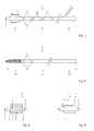
- Fig. 1 shows a first catheter 1 (hereinafter also “outer catheter”), which serves as a device for the endovenous treatment of varicosis and which is insertable into a vein.
- the catheter 1 has a proximal end portion 1a with a balloon 2, which in the Fig. 1 is shown in a sectional view and in the expanded state and which carries cutting elements 3, and a distal end portion 1 b having an inlet opening 4 and a port 5, which via a side channel 1 e (“lumen”) is fluidly connected to the balloon 2 (see. Fig. 5 ).
- a syringe or the like can be connected to the connection 5, in order to pump a fluid into the balloon 2 via the secondary passage 1e or to discharge it again, thus allowing the balloon 2 to be deflated and deflated.
- air is not used as the inflation fluid, but a liquid such as a sodium chloride solution.
- the proximal end portion 1a includes a tapered end provided with a continuous end opening 6. This is fluidically connected to the inlet opening 4 via a main channel 1d ("lumen") (cf. Fig. 5 ).
- the catheter 1 is fenestrated. For this purpose, it has between the two end portions 1a and 1b on an intermediate part 1c, which is provided with side openings 7a-7c ("catheter window"). These are distributed around the circumference of the catheter 1 around and fluidly connected to the inlet opening 4 via the main channel 1d.
- a sclerosant is injectable into the vein to be treated via the side openings 7a-7c.
- Two adjacent side openings 7a-7c are arranged axially and radially offset from one another. The offset allows the most homogeneous possible distribution of sclerosant in the vein.
- marks 8 are provided on the catheter shaft, which are for example mounted at regular intervals and provide, inter alia, information about how far the catheter 1 is inserted into a vein.
- Marks 8 are shown in the form of dashes and numbers 0, 10, 20, 30. Of course, other types of markings are possible.
- the side openings 7a-7c are arranged in groups so that the intermediate part 1c is divided into sections each having the same arrangement on side openings 7a-7c.
- a group with three side openings 7a can be seen.
- the same arrangement of side openings is repeated in sections 10 to 20 and 20 to 30, respectively.
- the side openings 7a, 7b, 7c in FIG the respective group are arranged radially offset by an angle. In the example with three side openings, this angle can be 120 degrees. However, it is also an uneven radial distribution conceivable.
- the number of side openings 7a-7c per group or section other than in Fig. 1 be shown and be one, two or more.
- the number and arrangement are chosen so that there is sufficient space to provide at least one sealed side channel from the connection 5 to the balloon 2 (cf., side channel 1 e in FIG Fig. 5 ).
- a second catheter 20 (hereinafter also “inner catheter”) can be inserted, as in Fig. 2 is shown.
- the catheter 20 has a proximal end portion 20 a and a distal end portion 20 b with a port 24.
- the proximal end portion 20a is formed by a closed wall.
- the tapered end 26 is free of an end opening.
- the closed end 26 of the inner catheter 20 allows occlusion of the lumen at the tip of the outer catheter 1, thereby preventing proximal leakage when sclerosant is applied.
- the catheter 20 has an intermediate part 20c, which has an inner channel (“lumen”) and which is provided with side openings 27. These are fluidly connected to the port 24 via the inner channel.
- the catheter 20 is then provided to the proximal end portion 20a only on a portion with side openings 27, while the rest of the catheter shaft has no openings.
- only one group of lateral openings 27 is provided.
- the number and / or arrangement of the side openings 27 corresponds to the number or arrangement of the first group of side openings 7a in the outer catheter 1.
- three side openings 27 can be seen, which are arranged radially and axially offset from each other similar to the side openings 7a in Fig. 1 , Depending on the design, the number of side openings 27 may be one, two or more.
- markers 28 are provided, which are for example mounted at regular intervals and provide, inter alia, information about how far the catheter 20 is inserted into the outer catheter 1.
- markings 28 are used, for example, dashes, numbers, etc.
- the inner catheter 20 is received in the outer catheter 1 and is then partially withdrawn.
- the side openings 28 are first in the vicinity of the side openings 7a, then at the side openings 7b, etc.
- the sealed end portion 20a of the inner catheter 20 seals the main channel 1 d of the outer catheter 1 between the ends 6 and 26.
- a sclerosing agent can thus be introduced in sections into the vein to be treated.
- FIG 3 and 4 show the configuration of the proximal end portion 1a of the outer catheter 1 in detail, wherein the balloon 2 is shown in the expanded state.
- the direction in which the axis A extends, along which the outer catheter 1 extends from the end section 1a to the end section 1b, while “radially” is transverse to the axis A is referred to as "axial".
- the balloon 2 is a "Cutting Balloon" and for this purpose has one or more cutting elements 3 ("blades").
- blades a plurality of cutting elements 3 are shown, which extend parallel to each other in the axial direction and which are arranged around the balloon 2 around.
- a respective cutting element 3 does not run straight in the axial direction A, but its cutting edge 3c has a curved course at least along a section.
- the cutting edge 3c may be curved so that it winds around the axis A, e.g. helically. It is also conceivable that viewed in the direction of the axis A, the cutting edge 2a has a section with a straight axial course, which merges again into a straight section via a curved intermediate section. It is also conceivable to provide only a single cutting element 3, which extends around the axis A.
- the odd course of a cutting element 3 causes seen in the axial direction A, the ends 3a and 3b of a cutting element 3 are arranged radially offset by an angle which is greater than 0 degrees.
- the angle is at least 10 degrees, and more preferably at least 20 degrees.
- the course may be such that said angle is less than 360 degrees. It is preferably at most 180 degrees, and more preferably at most 90 degrees.
- a cutting element 3 also changes transversely to the axis A, in that the cutting edge 3c extends at a height which decreases in the direction towards the distal end section 1b.
- the distal end 3b of the cutting element 3 is thus closer to the center of the axis A than the proximal end 3a.
- the cutting element 3 is wedge-shaped.
- the maximum height H of a cutting element 3 is typically in the range of 0.5 - 1.5 mm.
- the balloon 2 extends axially for a length L which is typically in the range of 5 to 30 mm.
- a cutting element 3 allows a comprehensive mechanical action on a venous inner wall, when the introduced into the vein catheter 1 is pulled out again.
- the tapered cutting edges 3c gradually dig into the internal wall of the vein, similar to a plow. Therefore, an abrupt mechanical action is avoided so that a painless treatment is possible, which under certain circumstances can also take place without local anesthesia in the form of tumescent anesthesia. This is for example the case when Aethoxysklerol ® is used as a sclerosing agent, which indeed is also a local anesthetic.
- Fig. 5 shows the proximal end portion 1a of the outer catheter 1 in a partially sectioned longitudinal section, wherein the balloon 2 is shown in the unexpanded state.
- the catheter 1 comprises an outer wall 1f defining the main channel 1d.
- a wire is previously used as a guide, which is inserted into the vein and over which the outer catheter 1 is pushed, so that the wire passes through the end opening 6, the main channel 1 d and the inlet opening 4.
- the balloon 2 is formed by a shell which extends around the outer wall 1f and which surrounds a chamber 2a. This is connected via at least one through opening 1 g formed in the outer wall 1 f to the auxiliary channel 1 e, which leads to the inlet opening 4. On the shell 2, the cutting elements 3 are attached. The shell of the balloon 2 is folded in the deflated state that results in the smallest possible extent in the radial direction.
- the device with the catheters 1 and 20 according to Fig. 1 and 2 is particularly suitable for the treatment of large-caliber veins, eg trunk veins.
- 6 and 7 show Another embodiment of the device with catheters 1 ', 20', which is especially for smaller veins, eg side branches, can be used.
- Fig. 6 shows a part of the outer catheter 1 ', which has the same elements 2-8 as the outer catheter 1 according Fig. 1 ,
- a one-way valve 11 for example in the form of a non-return valve, is additionally arranged at the proximal end section 1a 'in the main channel 1d.
- the one-way valve 11 is used to close the end opening 6, so that in the caudal direction, ie from the outside into the main channel 1 d in (see arrow K in Fig. 6 ) is passable, but not in the opposite direction.
- a wire which has been introduced as a guide in a vein to be treated, in the direction K via the inlet opening 6 in the main channel 1 d of the outer catheter 1 'receivable, while sclerosant, which is located in the main channel 1 d, not via the end opening 6 can go outside.
- Fig. 7 shows the inner catheter 20 ', wherein the distal end portion 20b with the terminal 24 that of the inner catheter 20 according to Fig. 2 equivalent.
- the inner catheter 20 ' is free from side openings 27.
- the proximal end 26 'of the inner catheter 20' opens into a continuous outlet opening 27 '.
- sclerosant can be introduced via the connection 24 into the main channel 30, from where it can reach the vein to be treated via the outlet opening 27 'and via the side openings 7a-7c of the outer catheter 1' can.
- a vein is treatable in sections by alternately injecting sclerosant and the inner catheter 20 'is pulled back a bit.
- the outlet opening 27 ' comes successively in the vicinity of the side openings 7a, 7b, 7c, etc. to lie.
- the catheters 1, 1, 20, 20 ' For the manufacture of the catheters 1, 1, 20, 20 ', common materials can be used which can be sterilized.
- the catheters 1, 20 and 1, '20' are designed for disposable use and are provided in packages in sterile form.
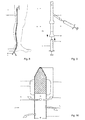
- Fig. 8 shows a leg with the saphenous vein VSM and a sluice S, which was introduced into the vein by means of Sedlinger technique.
- the catheter 1 is introduced via the sluice S, ultrasonographically advanced over the trunk vein VSM and the tip is placed 1.5 cm caudal to the crosse. Subsequently, the balloon 2 is inflated by means of a syringe S1 attached to the connection 5. He stays that way throughout the sclerotherapy phase (step 2).
- the wire, if any, is removed and the inner catheter 20 is inserted into the main channel 1d. If no wire is used, the inner catheter 20 may already be inserted at the beginning in the outer catheter 1, so that both catheters 1, 20 can be introduced together into the vein.
- connection 24 attached to the syringe S2 is transferred to the inner catheter 20, the sclerosing agent (preferably as a foam, for example Aethoxysklerol ® 1% polidocanol or other containing means), respectively.
- the inner catheter 20 is pulled out in 10 cm increments. Per 10 cm in each case 1 ml is applied Aethoxysklerol ® 1% as a foam, and maintained for about 1 minute. It will continue to process until the entire inner catheter 20 is removed.
- Fig. 9 the application is indicated by the arrow P1 and the retraction of the inner catheter 20 by the arrow P2.
- Fig. 10 in which the outer catheter 1 is shown in section and the inner catheter 20 is inserted completely therein, the arrows P3 indicate the escape of the sclerosing agent from the side openings 27 and 7a.
- the lumen of the inner catheter 20 is formed closed at the proximal end. This closed area, which goes up to the 0 mark, for example, is in Fig. 10 indicated by the double arrow at 20a
- the action of the sclerosant has led to vasospasm.
- the sensitivity to pain should be reduced.
- the balloon 2 is deflated for about 20 seconds and then inflated again.
- the vein VSM can "empty" itself. Now the catheter 1 with the inflated balloon 2 is slowly withdrawn (about 3 seconds for 10 cm). When pulling back, the resistance should be well felt, but a "tearing" should be avoided.
- the mechanical action of a cutting element 3 on the balloon 2 destroys the intima and media of the vein.
- the special shaping of a cutting element 3 allows effective destruction of the internal wall of the vein, which is cut into multiple fragments when the balloon 2 is withdrawn.
- the device according to the second embodiment can be used analogously as described above.
- the inner catheter 20 'can already be used at the beginning in the outer catheter 1', since during insertion of the catheter 1 ', 20' into a vein, the wire through the end openings 6, 27 'and the one-way valve 11 into the interior the catheter 20 'can pass.
Landscapes
- Health & Medical Sciences (AREA)
- Life Sciences & Earth Sciences (AREA)
- Surgery (AREA)
- Heart & Thoracic Surgery (AREA)
- General Health & Medical Sciences (AREA)
- Engineering & Computer Science (AREA)
- Animal Behavior & Ethology (AREA)
- Public Health (AREA)
- Veterinary Medicine (AREA)
- Biomedical Technology (AREA)
- Medical Informatics (AREA)
- Molecular Biology (AREA)
- Nuclear Medicine, Radiotherapy & Molecular Imaging (AREA)
- Orthopedic Medicine & Surgery (AREA)
- Vascular Medicine (AREA)
- Biophysics (AREA)
- Pulmonology (AREA)
- Anesthesiology (AREA)
- Hematology (AREA)
- Rheumatology (AREA)
- Child & Adolescent Psychology (AREA)
- Media Introduction/Drainage Providing Device (AREA)
Abstract
Description
- Die Erfindung betrifft eine Vorrichtung zur Behandlung der Varikose.
- Neben chirurgischen Verfahren und der Sklerotherapie zur Behandlung der Varikose gewannen in den letzten Jahren endovenöse Verfahren (Laser, Radiofrequenz, ClariVein®) zunehmend an Bedeutung. Zur Ablation von Stammvenen entpuppen sich diese Verfahren als effizient und für den Patienten weniger belastend als die herkömmlichen operativen Verfahren. Sowohl Laser, Radiofrequenz als auch ClariVein® brauchen jedoch ein relativ teures Equipment. Neben den Kathetern sind Apparate zur Erzeugung des Lasers bzw. der Radiofrequenzwellen notwendig. Bei ClariVein® (vgl. z.B.
WO 2013/090563 A1 ) wird durch einen sehr schnell rotierenden Draht mit einer speziell abgewinkelten Spitze innerhalb des Katheters, der gegen die Gefässinnenwand schlägt, ein Gefässspasmus erzeugt. Gleichzeitig wird flüssiges Verödungsmittel, Polidocanol, injiziert. Die sehr schnell rotierende Spitze führt ausserdem zu einem Verwirbeln des Verödungsmittels und damit zu einem gleichmässigen Kontakt mit der gesamten Veneninnenwand und verödet diese. - Insgesamt kommen bei den bekannten endovenösen Verfahren aufwändige Vorrichtungen zum Einsatz, welche die Behandlung teuer machen.
- Es ist daher Aufgabe der vorliegenden Erfindung, eine Vorrichtung mit einfacherem Aufbau anzugeben, die eine wirksame Behandlung der Varikose ermöglicht.
- Eine Vorrichtung, die diese Aufgabe löst, ist im Patentanspruch 1 angegeben. Die weiteren Patentansprüche geben bevorzugte Ausführungen an.
- Die Vorrichtung gemäss Anspruch 1 umfasst einen Katheter, welcher einen Ballon mit mindestens einem Schneidelement ("Cutting Balloon") und welcher Seitenöffnungen aufweist. Über diese kann ein Sklerosierungsmittel in die Vene gelangen. Mittels des "Cutting Balloon" kann zumindest ein Teil der Veneninnenwand zerschnitten werden, um so die Zerstörung der Intima und Media der Vene herbeizuführen. Die Vorrichtung erlaubt somit eine Behandlung in Form einer endovenösen chemomechanischen Katheterablation. Aufgrund der Kombination einer Sklerotherapie mit einer mechanischen Zerstörung der insuffizienten Vene ist die Behandlungswirksamkeit gegenüber einer alleinigen Sklerotherapie heraufsetzbar. Im Vergleich zu den herkömmlichen endovenösen Verfahren ist kein zusätzlicher Einsatz von aufwändigen apparativen Hilfsmitteln notwendig. Insgesamt ist bei der erfindungsgemässen Vorrichtung der Aufbau relativ einfach und der apparative Aufwand reduzierbar, wobei eine wirksame sowie zeit- und kostengünstige Behandlung ermöglicht wird.
- Weitere spezifische Konstruktionsmerkmale der Vorrichtung und deren Vorteile sind aus folgender Beschreibung und Zeichnungen von Ausführungsbeispielen ersichtlich. Es zeigen
-
Fig. 1 ein erstes Ausführungsbeispiel eines Aussenkatheters einer Vorrichtung zur Behandlung der Varikose in einer teilweise geschnittenen Seitenansicht, -
Fig. 2 eine Seitenansicht eines Innenkatheters, der im Aussenkatheter gemässFig. 1 aufnehmbar ist, -
Fig. 3 den proximalen Endabschnitt des Aussenkatheters gemässFig. 1 in einer Ansicht von oben, -
Fig. 4 den proximalen Endabschnitt gemässFig. 3 in einem Längsschnitt, so dass ein Schneidelement von der Seite zu sehen ist, -
Fig. 5 den proximalen Endabschnitt des Aussenkatheters gemässFig. 1 in einer teilweise geschnittenen Seitenansicht, -
Fig. 6 ein zweites Ausführungsbeispiel eines Aussenkatheters einer Vorrichtung in einer teilweise geschnittenen Seitenansicht, -
Fig. 7 einen Innenkatheter in einer teilweise geschnittenen Seitenansicht, der im Aussenkatheter gemässFig. 6 aufnehmbar ist, -
Fig. 8 schematisch ein Bein mit der Stammvene, in welche die Katheter ausFig. 1 und 2 eingefügt sind, -
Fig. 9 das distale Ende der zusammengefügten Katheter ausFig. 1 und 2 mit angeschlossenen Spritzen, und -
Fig. 10 das proximale Ende der zusammengefügten Katheter ausFig. 1 und 2 , wobei der Aussenkatheter geschnitten dargestellt ist. -
Fig. 1 zeigt einen ersten Katheter 1 (im Folgenden auch "Aussenkatheter"), der als Vorrichtung zur endovenösen Behandlung der Varikose dient und der in eine Vene einführbar ist. Der Katheter 1 weist einen proximalen Endabschnitt 1a mit einem Ballon 2 auf, welcher in derFig. 1 in einer Schnittansicht und im expandierten Zustand gezeigt ist und welcher Schneidelemente 3 trägt, und einen distalen Endabschnitt 1 b mit einer Eingangsöffnung 4 und einem Anschluss 5, welcher über einen Nebenkanal 1e ("Lumen") fluidisch mit dem Ballon 2 verbunden ist (vgl.Fig. 5 ). Am Anschluss 5 ist z.B. eine Spritze oder drgl. anschliessbar, um über den Nebenkanal 1e ein Fluid in den Ballon 2 zu pumpen bzw. aus diesem wieder abzulassen und so ein In- und Deflatieren des Ballons 2 zu ermöglichen. Um einen Patienten durch eine etwaige Undichtigkeit des in die Vene eingeführten Ballons 2 nicht zu gefährden, wird nicht Luft als Fluid zum Inflatieren verwendet, sondern eine Flüssigkeit, beispielsweise eine Natriumchloridlösung. Der proximale Endabschnitt 1a umfasst ein sich verjüngendes Ende, welches mit einer durchgehenden Endöffnung 6 versehen ist. Diese ist über einen Hauptkanal 1d ("Lumen") fluidisch mit der Eingangsöffnung 4 verbunden (vgl.Fig. 5 ). - Der Katheter 1 ist fenestriert. Zu diesem Zweck weist er zwischen den beiden Endabschnitten 1a und 1b einen Zwischenteil 1c auf, der mit Seitenöffnungen 7a-7c ("Katheterfenster") versehen ist. Diese sind um den Umfang des Katheters 1 herum verteilt angeordnet und über den Hauptkanal 1d mit der Eingangsöffnung 4 fluidisch verbunden. Bei der Anwendung ist über die Seitenöffnungen 7a-7c ein Sklerosierungsmittel in die zu behandelnde Vene injizierbar. Zwei benachbarte Seitenöffnungen 7a-7c sind axial und radial versetzt zueinander angeordnet. Der Versatz erlaubt eine möglichst homogene Verteilung von Sklerosierungsmittel in der Vene.
- Entlang des Zwischenteils 1 c sind auf dem Katheterschaft Markierungen 8 vorgesehen, die beispielsweise in regelmässigen Abständen angebracht sind und u.a. Angaben darüber liefern, wie weit der Katheter 1 in eine Vene eingeführt ist. In der Variante gemäss
Fig. 1 sind Markierungen 8 in Form von Strichen und Zahlen 0, 10, 20, 30 zu sehen. Natürlich sind auch andere Arten von Markierungen möglich. - Die Seitenöffnungen 7a-7c sind in Gruppen angeordnet, so dass der Zwischenteil 1c in Abschnitte unterteilt ist, die jeweils die gleiche Anordnung an Seitenöffnungen 7a-7c aufweist. In der Variante gemäss
Fig. 1 ist z.B. zwischen dem Abschnitt 0 bis 10 eine Gruppe mit drei Seitenöffnungen 7a zu sehen. Dieselbe Anordnung an Seitenöffnungen wiederholt sich im Abschnitt 10 bis 20 bzw. 20 bis 30. Die Seitenöffnungen 7a, 7b, 7c in der jeweiligen Gruppe sind radial um einen Winkel versetzt angeordnet. Beim Beispiel mit drei Seitenöffnungen kann dieser Winkel 120 Grad betragen. Es ist jedoch auch eine ungleichmässige radiale Verteilung denkbar. Im Weiteren kann die Anzahl der Seitenöffnungen 7a-7c pro Gruppe bzw. Abschnitt anders als inFig. 1 gezeigt sein und eins, zwei oder mehr betragen. Da die Seitenöffnungen 7a-7c durch die Aussenwandung des Katheters 1 hindurchreichen, sind Anzahl und Anordnung so gewählt, dass genügend Platz bleibt, um zumindest einen abgeschlossenen Nebenkanal vom Anschluss 5 zum Ballon 2 vorsehen zu können (vgl. Nebenkanal 1 e inFig. 5 ). - Über die Eingangsöffnung 4 des Aussenkatheters 1 ist ein zweiter Katheter 20 (im Folgenden auch "Innenkatheter") einführbar, wie er in
Fig. 2 gezeigt ist. Der Katheter 20 weist einen proximalen Endabschnitt 20a und einen distalen Endabschnitt 20b mit einem Anschluss 24 auf. Der proximale Endabschnitt 20a ist durch eine geschlossene Wandung gebildet. Insbesondere ist im Gegensatz zum Aussenkatheter 1 das sich verjüngende Ende 26 frei von einer Endöffnung. Das geschlossene Ende 26 des Innenkatheters 20 erlaubt ein Verschliessen des Lumen an der Spitze des Aussenkatheters 1, wodurch bei der Anwendung von Sklerosierungsmittel ein Wegfliessen nach proximal verhindert wird. - Zwischen den beiden Endabschnitten 20a und 20b weist der Katheter 20 einen Zwischenteil 20c auf, der einen Innenkanal ("Lumen") aufweist und der mit Seitenöffnungen 27 versehen ist. Diese sind über den Innenkanal fluidisch mit dem Anschluss 24 verbunden. Wie aus
Fig. 2 ersichtlich, ist der Katheter 20 anschliessend zum proximalen Endabschnitt 20a lediglich auf einem Teilabschnitt mit Seitenöffnungen 27 versehen, während der übrige Katheterschaft keine Öffnungen aufweist. Es ist somit im Gegensatz zum Aussenkatheter 1 nur eine Gruppe an Seitenöffnungen 27 vorgesehen. Vorzugsweise entspricht die Anzahl und/oder Anordnung der Seitenöffnungen 27 der Anzahl bzw. Anordnung der ersten Gruppe an Seitenöffnungen 7a beim Aussenkatheter 1. Im Beispiel gemässFig. 2 sind drei Seitenöffnungen 27 zu sehen, die radial und axial versetzt zueinander angeordnet sind ähnlich wie die Seitenöffnungen 7a inFig. 1 . Je nach Auslegung kann die Anzahl der Seitenöffnungen 27 eins, zwei oder mehr betragen. - Entlang des Zwischenteils 20c des Katheters 20 sind Markierungen 28 vorgesehen, die beispielsweise in regelmässigen Abständen angebracht sind und u.a. Angaben darüber liefern, wie weit der Katheter 20 in den Aussenkatheter 1 eingeführt ist. Als Markierungen 28 dienen z.B. Striche, Zahlen, etc.
- Bei der Anwendung ist der Innenkatheter 20 im Aussenkatheter 1 aufgenommen und wird dann abschnittsweise zurückgezogen. Dabei befinden sich die Seitenöffnungen 28 zuerst in der Nähe der Seitenöffnungen 7a, anschliessend bei den Seitenöffnungen 7b, usw. Der verschlossene Endabschnitt 20a des Innenkatheters 20 dichtet dabei den Hauptkanal 1 d des Aussenkatheters 1 zwischen den Enden 6 und 26 ab. Über den Anschluss 24 und die Seitenöffnungen 27 und 7a-7c ist somit ein Sklerosierungsmittel abschnittsweise in die zu behandelnde Vene einleitbar.
-
Fig. 3 und 4 zeigen die Ausgestaltung des proximalen Endabschnitts 1a des Aussenkatheters 1 im Detail, wobei der Ballon 2 im expandierten Zustand dargestellt ist. Im Folgenden wird als "axial" die Richtung bezeichnet, in welcher die Achse A verläuft, entlang welcher sich der Aussenkatheter 1 vom Endabschnitt 1 a zum Endabschnitt 1 b erstreckt, während "radial" quer zur Achse A ist. - Der Ballon 2 ist ein "Cutting Balloon" und weist zu diesem Zweck ein oder mehrere Schneidelemente 3 ("Klingen") auf. In
Fig. 3 sind mehrere Schneidelemente 3 gezeigt, die sich parallel zueinander in axialer Richtung erstrecken und die um den Ballon 2 herum angeordnet sind. Wie ersichtlich, verläuft ein jeweiliges Schneidelement 3 in axialer Richtung A gesehen nicht gerade, sondern seine Schnittkante 3c weist zumindest entlang eines Abschnitts einen gekrümmten Verlauf auf. - Es sind vielfältige Formen an Verläufen denkbar. Beispielsweise kann die Schnittkante 3c so gekrümmt sein, dass sie sich um die Achse A windet, z.B. schraubenförmig. Es ist auch denkbar, dass in Richtung der Achse A gesehen die Schnittkante 2a einen Abschnitt mit einem geraden axialen Verlauf aufweist, der über einen gekrümmten Zwischenabschnitt wieder in einen geraden Abschnitt übergeht. Es ist auch denkbar, nur ein einzelnes Schneidelement 3 vorzusehen, welches um die Achse A verläuft.
- Der ungerade Verlauf eines Schneidelements 3 führt dazu, dass gesehen in der axialen Richtung A die Enden 3a und 3b eines Schneidelements 3 um einen Winkel radial versetzt angeordnet sind, der grösser als 0 Grad ist. Bevorzugt beträgt der Winkel mindestens 10 Grad und besonders bevorzugt mindestens 20 Grad. Im Weiteren kann der Verlauf so sein, dass besagter Winkel weniger als 360 Grad ist. Bevorzugt beträgt er höchstens 180 Grad und besonders bevorzugt höchstens 90 Grad.
- Wie aus
Fig. 4 ersichtlich, verändert sich die Form eines Schneidelements 3 auch quer zur Achse A, indem die Schneidkante 3c auf einer Höhe verläuft, die in Richtung zum distalen Endabschnitt 1 b hin abnimmt. Das distale Ende 3b des Schneidelements 3 befindet sich somit näher bei der Mitte der Achse A als das proximale Ende 3a. Im vorliegenden Ausführungsbeispiel ist das Schneidelement 3 keilförmig ausgebildet. Die maximale Höhe H eines Schneidelements 3 ist typischerweise im Bereich von 0.5 - 1.5 mm. - Der Ballon 2 erstreckt sich axial auf einer Länge L, welche typischerweise im Bereich von 5 - 30 mm liegt.
- Die sich axial bzw. radial veränderliche Formgebung eines Schneidelements 3 erlaubt eine umfassende mechanische Einwirkung auf eine Veneninnenwand, wenn der in die Vene eingeführte Katheter 1 wieder herausgezogen wird. Dabei graben sich die sich verjüngenden Schneidkanten 3c ähnlich eines Pflugs allmählich in die Veneninnenwand ein. Es wird daher eine abrupte mechanische Einwirkung vermieden, so dass eine schmerzfreiere Behandlung möglich ist, die unter Umständen auch ohne örtliche Betäubung in Form einer Tumeszenzanästhesie erfolgen kann. Dies ist z.B. dann der Fall, wenn Aethoxysklerol® als Sklerosierungsmittel eingesetzt wird, das ja auch ein Lokalanästhetikum ist.
-
Fig. 5 zeigt den proximalen Endabschnitts 1a des Aussenkatheters 1 in einem teilweise geschnittenen Längsschnitt, wobei der Ballon 2 im unaufgeblähten Zustand dargestellt ist. Der Katheter 1 umfasst eine Aussenwandung 1f, die den Hauptkanal 1d definiert. In diesen ist bei der Behandlung der Innenkatheter 20 aufnehmbar. Bei Bedarf kommt vorgängig ein Draht als Führungshilfe zum Einsatz, der in die Vene eingeführt wird und über welchen der Aussenkatheter 1 geschoben wird, so dass der Draht durch die Endöffnung 6, den Hauptkanal 1d und die Eingangsöffnung 4 hindurch verläuft. - Der Ballon 2 ist durch eine Hülle gebildet, welche um die Aussenwandung 1f herum verläuft und welche eine Kammer 2a umgibt. Diese ist über mindestens eine in der Aussenwandung 1f gebildete Durchgangsöffnung 1 g mit dem Nebenkanal 1 e verbunden, der zur Eingangsöffnung 4 führt. An der Hülle 2 sind die Schneidelemente 3 befestigt. Die Hülle des Ballons 2 ist im unaufgeblähten Zustand so zusammengefaltet, dass sich in radialer Richtung eine möglichst geringe Ausdehnung ergibt.
- Die Vorrichtung mit den Kathetern 1 und 20 gemäss
Fig. 1 und 2 ist besonders geeignet zur Behandlung von grosskalibrigen Venen, z.B. Stammvenen.Fig. 6 und 7 zeigen ein anderes Ausführungsbeispiel der Vorrichtung mit Kathetern 1', 20', welche besonders bei kleineren Venen, z.B. Seitenästen, einsetzbar ist. -
Fig. 6 zeigt einen Teil des Aussenkatheters 1', der dieselben Elemente 2-8 aufweist wie der Aussenkatheter 1 gemässFig. 1 . Im Unterschied zu diesem ist beim proximalen Endabschnitt 1a' im Hauptkanal 1d zusätzlich ein Einwegventil 11 z.B. in Form einer Rückschlagklappe angeordnet. Das Einwegventil 11 dient zum Verschliessen der Endöffnung 6, so dass diese in der kaudalen Richtung, d.h. von aussen in den Hauptkanal 1 d hinein (vgl. Pfeil K inFig. 6 ) passierbar ist, jedoch nicht in der Gegenrichtung. Somit ist z.B. ein Draht, der als Führungshilfe in eine zu behandelnde Vene eingeführt worden ist, in der Richtung K über die Eingangsöffnung 6 im Hauptkanal 1d des Aussenkatheters 1' aufnehmbar, währenddessen Sklerosierungsmittel, welches sich im Hauptkanal 1 d befindet, nicht über die Endöffnung 6 nach aussen gelangen kann. -
Fig. 7 zeigt den Innenkatheter 20', wobei der distale Endabschnitt 20b mit dem Anschluss 24 jenem des Innenkatheters 20 gemässFig. 2 entspricht. Im Unterschied zu diesem ist der Innenkatheter 20' frei von Seitenöffnungen 27. Somit ist die Aussenwandung 29, welche den zum Anschluss 24 führenden Kanal 30 umgibt, geschlossen ausgebildet. Das proximale Ende 26' des Innenkatheters 20' mündet in einer durchgehenden Austrittsöffnung 27'. - Ist der Innenkatheter 20' im Aussenkatheter 1' aufgenommen, so ist Sklerosierungsmittel über den Anschluss 24 in den Hauptkanal 30 einleitbar, von wo aus es über die Austrittsöffnung 27' und über die Seitenöffnungen 7a-7c des Aussenkatheters 1' in die zu behandelnde Vene gelangen kann. So wie beim ersten Ausführungsbeispiel ist eine Vene abschnittsweise behandelbar, indem abwechselnd Sklerosierungsmittel injiziert und der Innenkatheter 20' ein Stück weit zurückgezogen wird. Dabei kommt nacheinander die Austrittsöffnung 27' in der Nähe der Seitenöffnungen 7a, 7b, 7c, etc. zu liegen.
- Zur Fertigung der Katheter 1, 1, 20, 20' sind gängige Materialien einsetzbar, die sterilisierbar sind. Die Wandungen, welche die Kanäle der Katheter 1, 1, 20, 20' definieren, sind z.B. aus Kunststoff fertigbar, so dass ein flexibler Schlauch ausbildbar ist. Vorzugsweise sind die Katheter 1, 20 bzw. 1,' 20' für einen Einweggebrauch ausgelegt und werden in steriler Form in Verpackungen bereitgestellt.
- Nachfolgend wird anhand der
Fig. 8-10 eine mögliche Anwendung der Vorrichtung mit den Kathetern 1 und 20 genauer erläutert. -
Fig. 8 zeigt ein Bein mit der Vena saphena magna VSM und einer Schleuse S, die mittels Sedlinger-Technik in die Vene eingeführt wurde. - Der Katheter 1 wird über die Schleuse S eingeführt, ultraschall-kontrolliert über die Stammvene VSM vorgeschoben und die Spitze 1.5 cm kaudal der Crosse platziert. Anschliessend wird mittels einer am Anschluss 5 angebrachten Spritze S1 der Ballon 2 inflatiert. Er bleibt dies während der gesamten Sklerosierungsphase (2. Schritt).
- Ist ein direktes Vorschieben des Katheters 1 erschwert, kann vorgängig ein (in den
Fig. 8-10 nicht dargestellter) Draht als Führungshilfe in die Vene VSM eingeführt und anschliessend der Katheter 1 über diesen eingeschoben werden. - Eine etwaige Dissektion beim Anbringen des Katheters 1 und/oder des Drahtes ist unproblematisch, da ja die Vene sowieso zerstört werden soll.
- Nach Setzen des Aussenkatheters 1 wird der Draht, sofern vorhanden, entfernt und der Innenkatheter 20 in den Hauptkanal 1d eingeführt. Wird kein Draht verwendet, so kann der Innenkatheter 20 bereits zu Beginn im Aussenkatheter 1 eingesetzt sein, so dass beide Katheter 1, 20 zusammen in die Vene einführbar sind.
- Es folgt die Sklerosierung. Mittels einer am Anschluss 24 angebrachten Spritze S2 wird über den Innenkatheter 20 das Sklerosierungsmittel (vorzugsweise als Schaum, z.B. Aethoxysklerol® 1% oder ein anderes Polidocanol enthaltendes Mittel) zugeführt. Der Innenkatheter 20 wird in 10 cm-Schritten herausgezogen. Pro 10 cm wird jeweils 1 ml Aethoxysklerol® 1% als Schaum appliziert und ca. 1 Minute gewartet. Es wird so weiterverfahren, bis der gesamte Innenkatheter 20 entfernt ist.
- In
Fig. 9 ist das Applizieren durch den Pfeil P1 und das Zurückziehen des Innenkatheters 20 durch den Pfeil P2 angedeutet. - In
Fig. 10 , in welcher der Aussenkatheter 1 geschnitten dargestellt und der Innenkatheter 20 ganz darin eingeführt ist, sind durch die Pfeile P3 der Austritt des Sklerosierungsmittels aus den Seitenöffnungen 27 sowie 7a angedeutet. Wie weiter oben erläutert, ist das Lumen des Innenkatheters 20 am proximalen Ende verschlossen ausgebildet. Dieser verschlossene Bereich, der z.B. bis zur 0-Marke geht, ist inFig. 10 mit dem Doppelpfeil bei 20a angedeutet - Die Einwirkung des Sklerosierungsmittels hat zu einem Vasospasmus geführt. Zudem sollte auch die Schmerzempfindlichkeit vermindert sein. Der Ballon 2 wird für ca. 20 Sekunden deflatiert und anschliessend wieder inflatiert. Die Vene VSM kann sich so "entleeren". Nun wird der Katheter 1 mit dem inflatierten Ballon 2 langsam zurückgezogen (ca. 3 Sekunden für 10 cm). Beim Zurückziehen sollte der Widerstand gut spürbar sein, ein "Herausreissen" sollte aber vermieden werden. Durch die mechanische Einwirkung eines Schneidelements 3 auf dem Ballon 2 wird die Intima und Media der Vene zerstört. Die spezielle Formgebung eines Schneidelements 3 erlaubt eine wirksame Zerstörung der Veneninnenwand, die beim Zurückziehen des Ballons 2 in multiple Fragmente zerschnitten wird.
- Die Vorrichtung gemäss dem zweiten Ausführungsbeispiel ist analog einsetzbar wie oben beschrieben. Hier kann auch bei Verwendung eines Drahtes der Innenkatheter 20' bereits zu Beginn im Aussenkatheter 1' eingesetzt sein, da beim Einführen der Katheter 1', 20' in eine Vene der Draht durch die Endöffnungen 6, 27' und das Einwegventil 11 in das Innere das Katheters 20' gelangen kann.
- Aus der vorangehenden Beschreibung sind dem Fachmann zahlreiche Abwandlungen zugänglich, ohne den Schutzbereich der Erfindung zu verlassen, der durch die Ansprüche definiert ist.
- In einer einfacheren Ausführungsform ist es z.B. denkbar, den Innenkatheter 20, 20' wegzulassen und nur einen Katheter mit einem "Cutting Balloon" 2, 3 und den Seitenöffnungen 7a-7c vorzusehen.
Claims (16)
- Vorrichtung zur Behandlung der Varikose, umfassend einen Katheter (1, 1'), welcher in eine zu behandelnde Vene einführbar ist, wobei am proximalen Ende (1 a, 1 a') des Katheters ein Ballon (2) mit mindestens einem Schneidelement (3) zum Zerschneiden zumindest eines Teils der Veneninnenwand angeordnet ist und wobei der Katheter Seitenöffnungen (7a-7c) aufweist, durch welche hindurch ein Sklerosierungsmittel in die Vene einleitbar ist.
- Vorrichtung nach Anspruch 1, wobei sich der Katheter (1, 1') in der axialen Richtung (A) erstreckt und wobei das mindestens eine Schneidelement (3) eine Schneidkante (3c) aufweist, die zumindest im inflatierten Zustand des Ballons (2) einen Verlauf aufweist, der sich in axialer und/oder radialer Richtung verändert.
- Vorrichtung nach einem der vorangehenden Ansprüche, wobei das Schneidelement (3) zumindest auf einem Teilabschnitt gekrümmt ist und/oder eine Höhe aufweist, die zum distalen Ende (1b) hin gesehen abnimmt.
- Vorrichtung nach einem der vorangehenden Ansprüche, wobei gesehen in der axialen Richtung (A), in welcher sich der Katheter (1, 1') erstreckt, die Enden (3a, 3b) des Schneidelements (3) um einen Winkel radial versetzt angeordnet sind, der grösser als 0 Grad und/oder kleiner als 360 Grad ist, bevorzugt beträgt der Winkel mindestens 10 Grad und/oder höchstens 180 Grad, besonders bevorzugt beträgt der Winkel mindestens 20 Grad und/oder höchstens 90 Grad.
- Vorrichtung nach einem der vorangehenden Ansprüche, wobei zwei benachbarte Seitenöffnungen (7a-7c) axial und/oder radial versetzt zueinander angeordnet sind.
- Vorrichtung nach einem der vorangehenden Ansprüche, wobei der Katheter (1, 1') in Abschnitte unterteilt ist, die jeweils die gleiche Anzahl und/oder Anordnung der Seitenöffnungen (7a-7c) aufweist.
- Vorrichtung nach einem der vorangehenden Ansprüche, wobei der Katheter (1, 1') mindestens einen Nebenkanal (1e) aufweist, der radial versetzt zu einem Hauptkanal (1d) angeordnet ist und der den Ballon (2) fluidisch mit einem Anschluss (5) verbindet.
- Vorrichtung nach einem der vorangehenden Ansprüche, wobei das proximale Ende (1 a, 1 a') des Katheters (1, 1') eine Endöffnung (6) aufweist.
- Vorrichtung nach einem der vorangehenden Ansprüche, wobei der Katheter (1') am proximalen Ende (1a') ein Einwegventil (11) aufweist.
- Vorrichtung nach einem der vorangehenden Ansprüche, wobei der Katheter ein Aussenkatheter (1, 1') ist, in welchen zumindest ein Teil eines Innenkatheters (20, 20') aufnehmbar ist.
- Vorrichtung nach Anspruch 10, wobei der Innenkatheter (20, 20') einen Anschluss (24) zum Einleiten von Sklerosierungsmittel und mindestens eine Öffnung (27, 27') aufweist, durch welche hindurch Sklerosierungsmittel zu den Seitenöffnungen (7a-7c) des Aussenkatheters (1, 1') leitbar ist, wenn der Innenkatheter (20, 20') im Aussenkatheter (1, 1') eingeführt ist.
- Vorrichtung nach einem der Ansprüche 10-11, wobei der Innenkatheter (20) ein verschlossenes proximales Ende (20a) und anschliessend dazu einen Teilabschnitt mit mindestens einer Seitenöffnung (27) aufweist.
- Vorrichtung nach Anspruch 12, wobei anschliessend zum Teilabschnitt der Innenkatheter (20) bis zum distalen Ende (20b) verschlossen ausgebildet ist.
- Vorrichtung nach einem der Ansprüche 10-13, wobei der Innenkatheter (20) Seitenöffnungen (27) mit einer Anzahl aufweist, die kleiner als die Anzahl der Seitenöffnungen (7a-7c) des Aussenkatheters (1) ist, vorzugsweise stimmt die Anzahl und besonders bevorzugt auch die Anordnung der Seitenöffnungen (27) des Innenkatheters (20) mit auf einem Abschnitt des Aussenkatheters (1) angeordneten Seitenöffnungen (7a-7c) überein.
- Vorrichtung nach einem der Ansprüche 10-14, wobei der Innenkatheter (20') am proximalen Ende (26') eine Endöffnung aufweist (27') und vorzugsweise vom proximalen bis zum distalen Ende verschlossen ausgebildet ist.
- Vorrichtung nach einem der vorangehenden Ansprüche, wobei der Aussenkatheter (1, 1') und/oder Innenkatheter (20, 20') Markierungen (8, 28) zur Längenangabe aufweist, die vorzugsweise in regelmässigen Abständen angeordnet sind.
Priority Applications (2)
| Application Number | Priority Date | Filing Date | Title |
|---|---|---|---|
| EP15183162.5A EP3135206B1 (de) | 2015-08-31 | 2015-08-31 | Vorrichtung zur behandlung der varikose |
| US15/252,320 US10300250B2 (en) | 2015-08-31 | 2016-08-31 | Device for the treatment of varicose veins |
Applications Claiming Priority (1)
| Application Number | Priority Date | Filing Date | Title |
|---|---|---|---|
| EP15183162.5A EP3135206B1 (de) | 2015-08-31 | 2015-08-31 | Vorrichtung zur behandlung der varikose |
Publications (2)
| Publication Number | Publication Date |
|---|---|
| EP3135206A1 true EP3135206A1 (de) | 2017-03-01 |
| EP3135206B1 EP3135206B1 (de) | 2020-01-15 |
Family
ID=54014652
Family Applications (1)
| Application Number | Title | Priority Date | Filing Date |
|---|---|---|---|
| EP15183162.5A Active EP3135206B1 (de) | 2015-08-31 | 2015-08-31 | Vorrichtung zur behandlung der varikose |
Country Status (2)
| Country | Link |
|---|---|
| US (1) | US10300250B2 (de) |
| EP (1) | EP3135206B1 (de) |
Cited By (1)
| Publication number | Priority date | Publication date | Assignee | Title |
|---|---|---|---|---|
| US12295586B2 (en) | 2020-05-07 | 2025-05-13 | Gefässpraxis Dr. Erpen AG | Device for closing a vein juncture in the treatment of varicose veins |
Families Citing this family (22)
| Publication number | Priority date | Publication date | Assignee | Title |
|---|---|---|---|---|
| US11357533B2 (en) | 2011-09-13 | 2022-06-14 | Venturemed Group, Inc. | Intravascular catheter having an expandable incising portion and abrasive surfaces |
| US10610255B2 (en) | 2011-09-13 | 2020-04-07 | John P. Pigott | Intravascular catheter having an expandable incising portion and medication delivery system |
| US11413062B2 (en) | 2011-09-13 | 2022-08-16 | Venturemed Group, Inc. | Methods for preparing a zone of attention within a vascular system for subsequent angioplasty with an intravascular catheter device having an expandable incising portion and an integrated embolic protection device |
| US10463387B2 (en) | 2011-09-13 | 2019-11-05 | John P. Pigott | Intravascular catheter having an expandable incising portion for incising atherosclerotic material located in a blood vessel |
| ES2791766T3 (es) | 2011-09-13 | 2020-11-05 | Pigott John P | Catéter intravascular que tiene una porción de incisión expansible |
| US12324603B2 (en) | 2011-09-13 | 2025-06-10 | Venturemed Group, Inc. | Intravascular catheter having an expandable incising portion |
| US11559325B2 (en) | 2011-09-13 | 2023-01-24 | Venturemed Group, Inc. | Intravascular catheter having an expandable incising portion and grating tool |
| US10130798B2 (en) | 2013-07-15 | 2018-11-20 | John P. Pigott | Balloon catheter having a retractable sheath and locking mechanism |
| US10315014B2 (en) | 2013-07-15 | 2019-06-11 | John P. Pigott | Balloon catheter having a retractable sheath and locking mechanism with balloon recapture element |
| US10828471B2 (en) | 2013-07-15 | 2020-11-10 | John P. Pigott | Balloon catheter having a retractable sheath |
| US11202892B2 (en) | 2013-07-15 | 2021-12-21 | John P. Pigott | Balloon catheter having a retractable sheath |
| EP3244815B1 (de) | 2015-01-13 | 2020-04-22 | Pigott, John, P. | Intravaskulärer katheter mit einem expandierbaren teil |
| US10603069B2 (en) | 2015-01-13 | 2020-03-31 | John P. Pigott | Intravascular catheter balloon device having a tool for atherectomy or an incising portion for atheromatous plaque scoring |
| US12569327B2 (en) | 2016-07-01 | 2026-03-10 | Venturemed Group, Inc. | Intravascular catheter having an expandable incising portion and embolic protection device |
| EP3366239B1 (de) | 2017-02-24 | 2020-08-12 | Pigott, John, P. | Intravaskulärer katheter mit einem ausdehnbaren schneidenden anteil und abrasiven flächen |
| EP3793459B1 (de) | 2018-05-18 | 2024-07-10 | National University of Ireland Galway | Vorrichtung zur denudation eines körperlumens |
| WO2021030380A1 (en) * | 2019-08-14 | 2021-02-18 | Lsi Solutions, Inc. | Device for vessel support and harvesting |
| CN111588442A (zh) * | 2020-06-11 | 2020-08-28 | 安徽省立医院(中国科学技术大学附属第一医院) | 一种球囊辅助下腔静脉穿刺针及其使用方法 |
| US12408932B2 (en) | 2022-03-23 | 2025-09-09 | Venturemed Group, Inc. | Intravascular device having feedback elements |
| US12558116B2 (en) | 2022-03-23 | 2026-02-24 | Venturemed Group, Inc. | Intravascular device for treating fistulas |
| WO2024105430A1 (es) | 2022-11-15 | 2024-05-23 | Fundacion Santa Fe De Bogota | Dispositivo de tratamiento de safena y várices asociadas y un procedimiento para su empleo en el cuerpo humano |
| CN121843741A (zh) * | 2023-07-14 | 2026-04-10 | 波士顿科学国际有限公司 | 血管刻痕装置 |
Citations (10)
| Publication number | Priority date | Publication date | Assignee | Title |
|---|---|---|---|---|
| EP1169970A1 (de) * | 2000-07-04 | 2002-01-09 | Transgene S.A. | Gerät zur Abreichung von einer Zusammensetzung in einem Kanal des menschlichen oder tierischen Körpers |
| US20030120256A1 (en) * | 2001-07-03 | 2003-06-26 | Syntheon, Llc | Methods and apparatus for sclerosing the wall of a varicose vein |
| US6726677B1 (en) * | 1995-10-13 | 2004-04-27 | Transvascular, Inc. | Stabilized tissue penetrating catheters |
| WO2004112569A2 (en) * | 2003-05-21 | 2004-12-29 | Yale University | Vascular ablation apparatus and method |
| EP1997443A2 (de) * | 2007-05-31 | 2008-12-03 | Olympus Medical Systems Corp. | Schneideinstrument |
| WO2009109967A1 (en) * | 2008-03-02 | 2009-09-11 | V.V.T. Medical Ltd. | Method and device for vein ablation |
| US20110218494A1 (en) * | 2008-11-12 | 2011-09-08 | Gerrans Lawrence J | Multi-Balloon Catheter for Extravasated Drug Delivery |
| EP2508223A1 (de) * | 2011-04-08 | 2012-10-10 | Sanovas, Inc. | Ballonkatheter mit Arzneimittelabgabesonde |
| WO2013090563A1 (en) | 2011-12-13 | 2013-06-20 | Vascular Insights, Llc | Adhesive-based varicose vein treatment |
| WO2015052703A2 (en) * | 2013-10-13 | 2015-04-16 | V.V.T. Med Ltd. | Vein ablation device and method |
Family Cites Families (5)
| Publication number | Priority date | Publication date | Assignee | Title |
|---|---|---|---|---|
| US5282484A (en) * | 1989-08-18 | 1994-02-01 | Endovascular Instruments, Inc. | Method for performing a partial atherectomy |
| EP0819014B1 (de) * | 1995-03-30 | 2003-02-05 | Heartport, Inc. | Endovaskulärerkatheter zum ableiten aus dem herz |
| US5908407A (en) * | 1997-07-25 | 1999-06-01 | Neuroperfusion, Inc. | Retroperfusion catheter apparatus and method |
| US8377083B2 (en) * | 2010-04-27 | 2013-02-19 | Medtronic Vascular, Inc. | Percutaneous methods and apparatus for creating native tissue venous valves |
| US20130030410A1 (en) * | 2010-11-23 | 2013-01-31 | William Joseph Drasler | Venous heated ablation catheter |
-
2015
- 2015-08-31 EP EP15183162.5A patent/EP3135206B1/de active Active
-
2016
- 2016-08-31 US US15/252,320 patent/US10300250B2/en active Active
Patent Citations (10)
| Publication number | Priority date | Publication date | Assignee | Title |
|---|---|---|---|---|
| US6726677B1 (en) * | 1995-10-13 | 2004-04-27 | Transvascular, Inc. | Stabilized tissue penetrating catheters |
| EP1169970A1 (de) * | 2000-07-04 | 2002-01-09 | Transgene S.A. | Gerät zur Abreichung von einer Zusammensetzung in einem Kanal des menschlichen oder tierischen Körpers |
| US20030120256A1 (en) * | 2001-07-03 | 2003-06-26 | Syntheon, Llc | Methods and apparatus for sclerosing the wall of a varicose vein |
| WO2004112569A2 (en) * | 2003-05-21 | 2004-12-29 | Yale University | Vascular ablation apparatus and method |
| EP1997443A2 (de) * | 2007-05-31 | 2008-12-03 | Olympus Medical Systems Corp. | Schneideinstrument |
| WO2009109967A1 (en) * | 2008-03-02 | 2009-09-11 | V.V.T. Medical Ltd. | Method and device for vein ablation |
| US20110218494A1 (en) * | 2008-11-12 | 2011-09-08 | Gerrans Lawrence J | Multi-Balloon Catheter for Extravasated Drug Delivery |
| EP2508223A1 (de) * | 2011-04-08 | 2012-10-10 | Sanovas, Inc. | Ballonkatheter mit Arzneimittelabgabesonde |
| WO2013090563A1 (en) | 2011-12-13 | 2013-06-20 | Vascular Insights, Llc | Adhesive-based varicose vein treatment |
| WO2015052703A2 (en) * | 2013-10-13 | 2015-04-16 | V.V.T. Med Ltd. | Vein ablation device and method |
Cited By (1)
| Publication number | Priority date | Publication date | Assignee | Title |
|---|---|---|---|---|
| US12295586B2 (en) | 2020-05-07 | 2025-05-13 | Gefässpraxis Dr. Erpen AG | Device for closing a vein juncture in the treatment of varicose veins |
Also Published As
| Publication number | Publication date |
|---|---|
| US20170056048A1 (en) | 2017-03-02 |
| EP3135206B1 (de) | 2020-01-15 |
| US10300250B2 (en) | 2019-05-28 |
Similar Documents
| Publication | Publication Date | Title |
|---|---|---|
| EP3135206B1 (de) | Vorrichtung zur behandlung der varikose | |
| DE69310498T2 (de) | Longitudinal hin- und herbewegliches Einschneidegerät | |
| DE69219878T2 (de) | Vorrichtung zur Aufweiten einer Stenose | |
| DE69533943T2 (de) | Vorrichtung zur durchführung von diagnostischen oder therapeutischen verfahren innerhalb der gallengänge | |
| DE69512030T2 (de) | Cerebral-dilator | |
| DE60204258T2 (de) | Feder zum Falten eines Katheterballons | |
| DE69434853T2 (de) | Radial expandierbarer Dilatator | |
| DE69518320T2 (de) | Örtlich biegsame dilatorhülse | |
| DE69703077T2 (de) | Vorrichtung zum Einscheiden und Aufdehnen von Bluttgefässen, mit einem sich verjüngenden Ballon | |
| EP2054118B1 (de) | Vorrichtung zur verringerung oder entfernung von stenosen | |
| DE102011009482B4 (de) | Sicherheitskanüle | |
| EP3072463B1 (de) | Medizinisches Kit bzw. Set zur Behandlung eines krankhaft veränderten Hohlorgans | |
| EP0630617A1 (de) | Aspirationskatheteranordnung | |
| DE102012204166A1 (de) | Mikrozugangs-Ausrüstung, welche eine angeschrägte Nadel umfasst | |
| EP0679408A2 (de) | Vorrichtung zum Einführen eines Katheters in einen Körperhohlraum | |
| DE3422597A1 (de) | Chirurgisches geraet zum einfuehren eines draenagerohres in koerperhohlraeume | |
| EP2606919A1 (de) | Schleuseneinrichtung zum Einführen eines Katheters | |
| DE102005021470A1 (de) | Einführhilfe für die perkutane Tracheostomie | |
| DE8910603U1 (de) | Vorrichtung zum Ausbringen von Blutgerinnseln aus Arterien und Venen | |
| EP3025760B1 (de) | Design für eine vereinfachte entfernung eines ballon applikators | |
| WO2016146640A1 (de) | Infusions -, dilatations- und aspirations - catheter (idac) | |
| EP3197530A1 (de) | Dehnbare einführschleuse | |
| DE3525917A1 (de) | Chirurgisches instrument fuer die entfernung von kleinen krampfadern | |
| EP3473197A1 (de) | Ballonkatheter | |
| DE102013104021B4 (de) | Medizinischer Katheter zum endovaskulären Temperieren von Blut, Behandlungssystem und Herstellungsverfahren |
Legal Events
| Date | Code | Title | Description |
|---|---|---|---|
| PUAI | Public reference made under article 153(3) epc to a published international application that has entered the european phase |
Free format text: ORIGINAL CODE: 0009012 |
|
| STAA | Information on the status of an ep patent application or granted ep patent |
Free format text: STATUS: THE APPLICATION HAS BEEN PUBLISHED |
|
| AK | Designated contracting states |
Kind code of ref document: A1 Designated state(s): AL AT BE BG CH CY CZ DE DK EE ES FI FR GB GR HR HU IE IS IT LI LT LU LV MC MK MT NL NO PL PT RO RS SE SI SK SM TR |
|
| AX | Request for extension of the european patent |
Extension state: BA ME |
|
| STAA | Information on the status of an ep patent application or granted ep patent |
Free format text: STATUS: REQUEST FOR EXAMINATION WAS MADE |
|
| 17P | Request for examination filed |
Effective date: 20170825 |
|
| RBV | Designated contracting states (corrected) |
Designated state(s): AL AT BE BG CH CY CZ DE DK EE ES FI FR GB GR HR HU IE IS IT LI LT LU LV MC MK MT NL NO PL PT RO RS SE SI SK SM TR |
|
| GRAP | Despatch of communication of intention to grant a patent |
Free format text: ORIGINAL CODE: EPIDOSNIGR1 |
|
| STAA | Information on the status of an ep patent application or granted ep patent |
Free format text: STATUS: GRANT OF PATENT IS INTENDED |
|
| INTG | Intention to grant announced |
Effective date: 20190731 |
|
| GRAS | Grant fee paid |
Free format text: ORIGINAL CODE: EPIDOSNIGR3 |
|
| GRAA | (expected) grant |
Free format text: ORIGINAL CODE: 0009210 |
|
| STAA | Information on the status of an ep patent application or granted ep patent |
Free format text: STATUS: THE PATENT HAS BEEN GRANTED |
|
| AK | Designated contracting states |
Kind code of ref document: B1 Designated state(s): AL AT BE BG CH CY CZ DE DK EE ES FI FR GB GR HR HU IE IS IT LI LT LU LV MC MK MT NL NO PL PT RO RS SE SI SK SM TR |
|
| REG | Reference to a national code |
Ref country code: GB Ref legal event code: FG4D Free format text: NOT ENGLISH Ref country code: CH Ref legal event code: EP |
|
| REG | Reference to a national code |
Ref country code: IE Ref legal event code: FG4D Free format text: LANGUAGE OF EP DOCUMENT: GERMAN |
|
| REG | Reference to a national code |
Ref country code: DE Ref legal event code: R096 Ref document number: 502015011512 Country of ref document: DE |
|
| REG | Reference to a national code |
Ref country code: AT Ref legal event code: REF Ref document number: 1224461 Country of ref document: AT Kind code of ref document: T Effective date: 20200215 |
|
| REG | Reference to a national code |
Ref country code: CH Ref legal event code: NV Representative=s name: AMMANN PATENTANWAELTE AG BERN, CH |
|
| REG | Reference to a national code |
Ref country code: NL Ref legal event code: MP Effective date: 20200115 |
|
| REG | Reference to a national code |
Ref country code: LT Ref legal event code: MG4D |
|
| PG25 | Lapsed in a contracting state [announced via postgrant information from national office to epo] |
Ref country code: PT Free format text: LAPSE BECAUSE OF FAILURE TO SUBMIT A TRANSLATION OF THE DESCRIPTION OR TO PAY THE FEE WITHIN THE PRESCRIBED TIME-LIMIT Effective date: 20200607 Ref country code: NO Free format text: LAPSE BECAUSE OF FAILURE TO SUBMIT A TRANSLATION OF THE DESCRIPTION OR TO PAY THE FEE WITHIN THE PRESCRIBED TIME-LIMIT Effective date: 20200415 Ref country code: FI Free format text: LAPSE BECAUSE OF FAILURE TO SUBMIT A TRANSLATION OF THE DESCRIPTION OR TO PAY THE FEE WITHIN THE PRESCRIBED TIME-LIMIT Effective date: 20200115 Ref country code: RS Free format text: LAPSE BECAUSE OF FAILURE TO SUBMIT A TRANSLATION OF THE DESCRIPTION OR TO PAY THE FEE WITHIN THE PRESCRIBED TIME-LIMIT Effective date: 20200115 Ref country code: NL Free format text: LAPSE BECAUSE OF FAILURE TO SUBMIT A TRANSLATION OF THE DESCRIPTION OR TO PAY THE FEE WITHIN THE PRESCRIBED TIME-LIMIT Effective date: 20200115 |
|
| PG25 | Lapsed in a contracting state [announced via postgrant information from national office to epo] |
Ref country code: BG Free format text: LAPSE BECAUSE OF FAILURE TO SUBMIT A TRANSLATION OF THE DESCRIPTION OR TO PAY THE FEE WITHIN THE PRESCRIBED TIME-LIMIT Effective date: 20200415 Ref country code: SE Free format text: LAPSE BECAUSE OF FAILURE TO SUBMIT A TRANSLATION OF THE DESCRIPTION OR TO PAY THE FEE WITHIN THE PRESCRIBED TIME-LIMIT Effective date: 20200115 Ref country code: IS Free format text: LAPSE BECAUSE OF FAILURE TO SUBMIT A TRANSLATION OF THE DESCRIPTION OR TO PAY THE FEE WITHIN THE PRESCRIBED TIME-LIMIT Effective date: 20200515 Ref country code: LV Free format text: LAPSE BECAUSE OF FAILURE TO SUBMIT A TRANSLATION OF THE DESCRIPTION OR TO PAY THE FEE WITHIN THE PRESCRIBED TIME-LIMIT Effective date: 20200115 Ref country code: GR Free format text: LAPSE BECAUSE OF FAILURE TO SUBMIT A TRANSLATION OF THE DESCRIPTION OR TO PAY THE FEE WITHIN THE PRESCRIBED TIME-LIMIT Effective date: 20200416 Ref country code: HR Free format text: LAPSE BECAUSE OF FAILURE TO SUBMIT A TRANSLATION OF THE DESCRIPTION OR TO PAY THE FEE WITHIN THE PRESCRIBED TIME-LIMIT Effective date: 20200115 |
|
| REG | Reference to a national code |
Ref country code: DE Ref legal event code: R097 Ref document number: 502015011512 Country of ref document: DE |
|
| PG25 | Lapsed in a contracting state [announced via postgrant information from national office to epo] |
Ref country code: SM Free format text: LAPSE BECAUSE OF FAILURE TO SUBMIT A TRANSLATION OF THE DESCRIPTION OR TO PAY THE FEE WITHIN THE PRESCRIBED TIME-LIMIT Effective date: 20200115 Ref country code: DK Free format text: LAPSE BECAUSE OF FAILURE TO SUBMIT A TRANSLATION OF THE DESCRIPTION OR TO PAY THE FEE WITHIN THE PRESCRIBED TIME-LIMIT Effective date: 20200115 Ref country code: EE Free format text: LAPSE BECAUSE OF FAILURE TO SUBMIT A TRANSLATION OF THE DESCRIPTION OR TO PAY THE FEE WITHIN THE PRESCRIBED TIME-LIMIT Effective date: 20200115 Ref country code: ES Free format text: LAPSE BECAUSE OF FAILURE TO SUBMIT A TRANSLATION OF THE DESCRIPTION OR TO PAY THE FEE WITHIN THE PRESCRIBED TIME-LIMIT Effective date: 20200115 Ref country code: LT Free format text: LAPSE BECAUSE OF FAILURE TO SUBMIT A TRANSLATION OF THE DESCRIPTION OR TO PAY THE FEE WITHIN THE PRESCRIBED TIME-LIMIT Effective date: 20200115 Ref country code: RO Free format text: LAPSE BECAUSE OF FAILURE TO SUBMIT A TRANSLATION OF THE DESCRIPTION OR TO PAY THE FEE WITHIN THE PRESCRIBED TIME-LIMIT Effective date: 20200115 Ref country code: CZ Free format text: LAPSE BECAUSE OF FAILURE TO SUBMIT A TRANSLATION OF THE DESCRIPTION OR TO PAY THE FEE WITHIN THE PRESCRIBED TIME-LIMIT Effective date: 20200115 Ref country code: SK Free format text: LAPSE BECAUSE OF FAILURE TO SUBMIT A TRANSLATION OF THE DESCRIPTION OR TO PAY THE FEE WITHIN THE PRESCRIBED TIME-LIMIT Effective date: 20200115 |
|
| PLBE | No opposition filed within time limit |
Free format text: ORIGINAL CODE: 0009261 |
|
| STAA | Information on the status of an ep patent application or granted ep patent |
Free format text: STATUS: NO OPPOSITION FILED WITHIN TIME LIMIT |
|
| 26N | No opposition filed |
Effective date: 20201016 |
|
| PG25 | Lapsed in a contracting state [announced via postgrant information from national office to epo] |
Ref country code: IT Free format text: LAPSE BECAUSE OF FAILURE TO SUBMIT A TRANSLATION OF THE DESCRIPTION OR TO PAY THE FEE WITHIN THE PRESCRIBED TIME-LIMIT Effective date: 20200115 |
|
| PG25 | Lapsed in a contracting state [announced via postgrant information from national office to epo] |
Ref country code: PL Free format text: LAPSE BECAUSE OF FAILURE TO SUBMIT A TRANSLATION OF THE DESCRIPTION OR TO PAY THE FEE WITHIN THE PRESCRIBED TIME-LIMIT Effective date: 20200115 Ref country code: SI Free format text: LAPSE BECAUSE OF FAILURE TO SUBMIT A TRANSLATION OF THE DESCRIPTION OR TO PAY THE FEE WITHIN THE PRESCRIBED TIME-LIMIT Effective date: 20200115 |
|
| PG25 | Lapsed in a contracting state [announced via postgrant information from national office to epo] |
Ref country code: MC Free format text: LAPSE BECAUSE OF FAILURE TO SUBMIT A TRANSLATION OF THE DESCRIPTION OR TO PAY THE FEE WITHIN THE PRESCRIBED TIME-LIMIT Effective date: 20200115 |
|
| REG | Reference to a national code |
Ref country code: BE Ref legal event code: MM Effective date: 20200831 |
|
| PG25 | Lapsed in a contracting state [announced via postgrant information from national office to epo] |
Ref country code: BE Free format text: LAPSE BECAUSE OF NON-PAYMENT OF DUE FEES Effective date: 20200831 |
|
| PG25 | Lapsed in a contracting state [announced via postgrant information from national office to epo] |
Ref country code: TR Free format text: LAPSE BECAUSE OF FAILURE TO SUBMIT A TRANSLATION OF THE DESCRIPTION OR TO PAY THE FEE WITHIN THE PRESCRIBED TIME-LIMIT Effective date: 20200115 Ref country code: MT Free format text: LAPSE BECAUSE OF FAILURE TO SUBMIT A TRANSLATION OF THE DESCRIPTION OR TO PAY THE FEE WITHIN THE PRESCRIBED TIME-LIMIT Effective date: 20200115 Ref country code: CY Free format text: LAPSE BECAUSE OF FAILURE TO SUBMIT A TRANSLATION OF THE DESCRIPTION OR TO PAY THE FEE WITHIN THE PRESCRIBED TIME-LIMIT Effective date: 20200115 |
|
| PG25 | Lapsed in a contracting state [announced via postgrant information from national office to epo] |
Ref country code: MK Free format text: LAPSE BECAUSE OF FAILURE TO SUBMIT A TRANSLATION OF THE DESCRIPTION OR TO PAY THE FEE WITHIN THE PRESCRIBED TIME-LIMIT Effective date: 20200115 Ref country code: AL Free format text: LAPSE BECAUSE OF FAILURE TO SUBMIT A TRANSLATION OF THE DESCRIPTION OR TO PAY THE FEE WITHIN THE PRESCRIBED TIME-LIMIT Effective date: 20200115 |
|
| P01 | Opt-out of the competence of the unified patent court (upc) registered |
Effective date: 20230501 |
|
| PGFP | Annual fee paid to national office [announced via postgrant information from national office to epo] |
Ref country code: LU Payment date: 20250822 Year of fee payment: 11 |
|
| PGFP | Annual fee paid to national office [announced via postgrant information from national office to epo] |
Ref country code: DE Payment date: 20250820 Year of fee payment: 11 |
|
| PGFP | Annual fee paid to national office [announced via postgrant information from national office to epo] |
Ref country code: GB Payment date: 20250820 Year of fee payment: 11 |
|
| PGFP | Annual fee paid to national office [announced via postgrant information from national office to epo] |
Ref country code: FR Payment date: 20250829 Year of fee payment: 11 Ref country code: AT Payment date: 20250821 Year of fee payment: 11 |
|
| PGFP | Annual fee paid to national office [announced via postgrant information from national office to epo] |
Ref country code: CH Payment date: 20250901 Year of fee payment: 11 |
|
| PGFP | Annual fee paid to national office [announced via postgrant information from national office to epo] |
Ref country code: IE Payment date: 20250820 Year of fee payment: 11 |