EP3135548B1 - Dispositif de frein - Google Patents
Dispositif de frein Download PDFInfo
- Publication number
- EP3135548B1 EP3135548B1 EP15783276.7A EP15783276A EP3135548B1 EP 3135548 B1 EP3135548 B1 EP 3135548B1 EP 15783276 A EP15783276 A EP 15783276A EP 3135548 B1 EP3135548 B1 EP 3135548B1
- Authority
- EP
- European Patent Office
- Prior art keywords
- parking brake
- brake
- mechanisms
- parking
- actuation
- Prior art date
- Legal status (The legal status is an assumption and is not a legal conclusion. Google has not performed a legal analysis and makes no representation as to the accuracy of the status listed.)
- Not-in-force
Links
Images







Classifications
-
- B—PERFORMING OPERATIONS; TRANSPORTING
- B60—VEHICLES IN GENERAL
- B60T—VEHICLE BRAKE CONTROL SYSTEMS OR PARTS THEREOF; BRAKE CONTROL SYSTEMS OR PARTS THEREOF, IN GENERAL; ARRANGEMENT OF BRAKING ELEMENTS ON VEHICLES IN GENERAL; PORTABLE DEVICES FOR PREVENTING UNWANTED MOVEMENT OF VEHICLES; VEHICLE MODIFICATIONS TO FACILITATE COOLING OF BRAKES
- B60T7/00—Brake-action initiating means
- B60T7/02—Brake-action initiating means for personal initiation
- B60T7/08—Brake-action initiating means for personal initiation hand actuated
- B60T7/10—Disposition of hand control
- B60T7/107—Disposition of hand control with electrical power assistance
-
- F—MECHANICAL ENGINEERING; LIGHTING; HEATING; WEAPONS; BLASTING
- F16—ENGINEERING ELEMENTS AND UNITS; GENERAL MEASURES FOR PRODUCING AND MAINTAINING EFFECTIVE FUNCTIONING OF MACHINES OR INSTALLATIONS; THERMAL INSULATION IN GENERAL
- F16D—COUPLINGS FOR TRANSMITTING ROTATION; CLUTCHES; BRAKES
- F16D65/00—Parts or details
- F16D65/14—Actuating mechanisms for brakes; Means for initiating operation at a predetermined position
- F16D65/16—Actuating mechanisms for brakes; Means for initiating operation at a predetermined position arranged in or on the brake
- F16D65/18—Actuating mechanisms for brakes; Means for initiating operation at a predetermined position arranged in or on the brake adapted for drawing members together, e.g. for disc brakes
-
- B—PERFORMING OPERATIONS; TRANSPORTING
- B60—VEHICLES IN GENERAL
- B60T—VEHICLE BRAKE CONTROL SYSTEMS OR PARTS THEREOF; BRAKE CONTROL SYSTEMS OR PARTS THEREOF, IN GENERAL; ARRANGEMENT OF BRAKING ELEMENTS ON VEHICLES IN GENERAL; PORTABLE DEVICES FOR PREVENTING UNWANTED MOVEMENT OF VEHICLES; VEHICLE MODIFICATIONS TO FACILITATE COOLING OF BRAKES
- B60T13/00—Transmitting braking action from initiating means to ultimate brake actuator with power assistance or drive; Brake systems incorporating such transmitting means, e.g. air-pressure brake systems
- B60T13/74—Transmitting braking action from initiating means to ultimate brake actuator with power assistance or drive; Brake systems incorporating such transmitting means, e.g. air-pressure brake systems with electrical assistance or drive
-
- B—PERFORMING OPERATIONS; TRANSPORTING
- B60—VEHICLES IN GENERAL
- B60T—VEHICLE BRAKE CONTROL SYSTEMS OR PARTS THEREOF; BRAKE CONTROL SYSTEMS OR PARTS THEREOF, IN GENERAL; ARRANGEMENT OF BRAKING ELEMENTS ON VEHICLES IN GENERAL; PORTABLE DEVICES FOR PREVENTING UNWANTED MOVEMENT OF VEHICLES; VEHICLE MODIFICATIONS TO FACILITATE COOLING OF BRAKES
- B60T13/00—Transmitting braking action from initiating means to ultimate brake actuator with power assistance or drive; Brake systems incorporating such transmitting means, e.g. air-pressure brake systems
- B60T13/74—Transmitting braking action from initiating means to ultimate brake actuator with power assistance or drive; Brake systems incorporating such transmitting means, e.g. air-pressure brake systems with electrical assistance or drive
- B60T13/741—Transmitting braking action from initiating means to ultimate brake actuator with power assistance or drive; Brake systems incorporating such transmitting means, e.g. air-pressure brake systems with electrical assistance or drive acting on an ultimate actuator
-
- B—PERFORMING OPERATIONS; TRANSPORTING
- B60—VEHICLES IN GENERAL
- B60T—VEHICLE BRAKE CONTROL SYSTEMS OR PARTS THEREOF; BRAKE CONTROL SYSTEMS OR PARTS THEREOF, IN GENERAL; ARRANGEMENT OF BRAKING ELEMENTS ON VEHICLES IN GENERAL; PORTABLE DEVICES FOR PREVENTING UNWANTED MOVEMENT OF VEHICLES; VEHICLE MODIFICATIONS TO FACILITATE COOLING OF BRAKES
- B60T13/00—Transmitting braking action from initiating means to ultimate brake actuator with power assistance or drive; Brake systems incorporating such transmitting means, e.g. air-pressure brake systems
- B60T13/74—Transmitting braking action from initiating means to ultimate brake actuator with power assistance or drive; Brake systems incorporating such transmitting means, e.g. air-pressure brake systems with electrical assistance or drive
- B60T13/746—Transmitting braking action from initiating means to ultimate brake actuator with power assistance or drive; Brake systems incorporating such transmitting means, e.g. air-pressure brake systems with electrical assistance or drive and mechanical transmission of the braking action
-
- B—PERFORMING OPERATIONS; TRANSPORTING
- B60—VEHICLES IN GENERAL
- B60T—VEHICLE BRAKE CONTROL SYSTEMS OR PARTS THEREOF; BRAKE CONTROL SYSTEMS OR PARTS THEREOF, IN GENERAL; ARRANGEMENT OF BRAKING ELEMENTS ON VEHICLES IN GENERAL; PORTABLE DEVICES FOR PREVENTING UNWANTED MOVEMENT OF VEHICLES; VEHICLE MODIFICATIONS TO FACILITATE COOLING OF BRAKES
- B60T8/00—Arrangements for adjusting wheel-braking force to meet varying vehicular or ground-surface conditions, e.g. limiting or varying distribution of braking force
- B60T8/17—Using electrical or electronic regulation means to control braking
-
- F—MECHANICAL ENGINEERING; LIGHTING; HEATING; WEAPONS; BLASTING
- F16—ENGINEERING ELEMENTS AND UNITS; GENERAL MEASURES FOR PRODUCING AND MAINTAINING EFFECTIVE FUNCTIONING OF MACHINES OR INSTALLATIONS; THERMAL INSULATION IN GENERAL
- F16D—COUPLINGS FOR TRANSMITTING ROTATION; CLUTCHES; BRAKES
- F16D65/00—Parts or details
- F16D65/14—Actuating mechanisms for brakes; Means for initiating operation at a predetermined position
- F16D65/16—Actuating mechanisms for brakes; Means for initiating operation at a predetermined position arranged in or on the brake
- F16D65/18—Actuating mechanisms for brakes; Means for initiating operation at a predetermined position arranged in or on the brake adapted for drawing members together, e.g. for disc brakes
- F16D65/183—Actuating mechanisms for brakes; Means for initiating operation at a predetermined position arranged in or on the brake adapted for drawing members together, e.g. for disc brakes with force-transmitting members arranged side by side acting on a spot type force-applying member
-
- B—PERFORMING OPERATIONS; TRANSPORTING
- B60—VEHICLES IN GENERAL
- B60T—VEHICLE BRAKE CONTROL SYSTEMS OR PARTS THEREOF; BRAKE CONTROL SYSTEMS OR PARTS THEREOF, IN GENERAL; ARRANGEMENT OF BRAKING ELEMENTS ON VEHICLES IN GENERAL; PORTABLE DEVICES FOR PREVENTING UNWANTED MOVEMENT OF VEHICLES; VEHICLE MODIFICATIONS TO FACILITATE COOLING OF BRAKES
- B60T1/00—Arrangements of braking elements, i.e. of those parts where braking effect occurs specially for vehicles
- B60T1/005—Arrangements of braking elements, i.e. of those parts where braking effect occurs specially for vehicles by locking of wheel or transmission rotation
-
- F—MECHANICAL ENGINEERING; LIGHTING; HEATING; WEAPONS; BLASTING
- F16—ENGINEERING ELEMENTS AND UNITS; GENERAL MEASURES FOR PRODUCING AND MAINTAINING EFFECTIVE FUNCTIONING OF MACHINES OR INSTALLATIONS; THERMAL INSULATION IN GENERAL
- F16D—COUPLINGS FOR TRANSMITTING ROTATION; CLUTCHES; BRAKES
- F16D2121/00—Type of actuator operation force
- F16D2121/18—Electric or magnetic
- F16D2121/24—Electric or magnetic using motors
-
- F—MECHANICAL ENGINEERING; LIGHTING; HEATING; WEAPONS; BLASTING
- F16—ENGINEERING ELEMENTS AND UNITS; GENERAL MEASURES FOR PRODUCING AND MAINTAINING EFFECTIVE FUNCTIONING OF MACHINES OR INSTALLATIONS; THERMAL INSULATION IN GENERAL
- F16D—COUPLINGS FOR TRANSMITTING ROTATION; CLUTCHES; BRAKES
- F16D2125/00—Components of actuators
- F16D2125/18—Mechanical mechanisms
- F16D2125/20—Mechanical mechanisms converting rotation to linear movement or vice versa
-
- F—MECHANICAL ENGINEERING; LIGHTING; HEATING; WEAPONS; BLASTING
- F16—ENGINEERING ELEMENTS AND UNITS; GENERAL MEASURES FOR PRODUCING AND MAINTAINING EFFECTIVE FUNCTIONING OF MACHINES OR INSTALLATIONS; THERMAL INSULATION IN GENERAL
- F16D—COUPLINGS FOR TRANSMITTING ROTATION; CLUTCHES; BRAKES
- F16D2125/00—Components of actuators
- F16D2125/18—Mechanical mechanisms
- F16D2125/20—Mechanical mechanisms converting rotation to linear movement or vice versa
- F16D2125/34—Mechanical mechanisms converting rotation to linear movement or vice versa acting in the direction of the axis of rotation
- F16D2125/42—Rack-and-worm gears
-
- F—MECHANICAL ENGINEERING; LIGHTING; HEATING; WEAPONS; BLASTING
- F16—ENGINEERING ELEMENTS AND UNITS; GENERAL MEASURES FOR PRODUCING AND MAINTAINING EFFECTIVE FUNCTIONING OF MACHINES OR INSTALLATIONS; THERMAL INSULATION IN GENERAL
- F16D—COUPLINGS FOR TRANSMITTING ROTATION; CLUTCHES; BRAKES
- F16D2125/00—Components of actuators
- F16D2125/18—Mechanical mechanisms
- F16D2125/58—Mechanical mechanisms transmitting linear movement
- F16D2125/60—Cables or chains, e.g. Bowden cables
-
- F—MECHANICAL ENGINEERING; LIGHTING; HEATING; WEAPONS; BLASTING
- F16—ENGINEERING ELEMENTS AND UNITS; GENERAL MEASURES FOR PRODUCING AND MAINTAINING EFFECTIVE FUNCTIONING OF MACHINES OR INSTALLATIONS; THERMAL INSULATION IN GENERAL
- F16D—COUPLINGS FOR TRANSMITTING ROTATION; CLUTCHES; BRAKES
- F16D63/00—Brakes not otherwise provided for; Brakes combining more than one of the types of groups F16D49/00 - F16D61/00
- F16D63/006—Positive locking brakes
Definitions
- the present invention relates to a brake device including independent left and right mechanisms, and relates to a technique for reducing an operating noise that occurs when a parking brake is actuated.
- a brake device has been proposed in which an electric motor is used as a driving source to generate a braking force and the braking force can be maintained even after supply of electricity to the electric motor is stopped.
- an operating noise is generated when a parking brake is actuated, and this operating noise may cause an uncomfortable feeling or annoyance.
- Specific examples of such operating noises include a noise that is generated from a ratchet fitted in a pressure generating mechanism, a noise that is generated when a lock mechanism is locked, and a noise that is generated when a pressure that causes a braking force increases, and there is a demand to reduce an uncomfortable feeling or annoyance caused by such a noise.
- Examples of methods for reducing the uncomfortable feeling or annoyance caused by an operating noise that occurs when the parking brake is actuated include a method to reduce the sound pressure level of the operating noise, and a method to reduce the likelihood that the noise will cause an uncomfortable feeling or annoyance.
- a method of optimizing the structures and configuration of a motor and a speed reducer (or a reduction gear) of an electric brake device equipped with an electric parking brake so as to reduce the operating noise has been proposed (Patent Document 1).
- Patent Document 2 a method of providing a projecting portion or a recessed portion of an engagement portion of a lock mechanism with an elastic portion to reduce the operating noise has been proposed (Patent Document 2).
- Patent Document 1 which optimizes the structures and configuration of the motor and the speed reducer, limits the structures and configuration of the motor and the speed reducer, resulting in a reduction in versatility of the electric brake device equipped with the parking brake.
- Patent Document 2 which provides the lock mechanism with the elastic portion, leads to complicated device structure and an increase in production cost. This technique is unable to reduce an operating noise caused by a gear rattle of the speed reducer which reduces the speed of rotation (or a number of rotation per a unit time) of the electric motor, an operating noise of an actuator of the lock mechanism, or the like.
- Patent Document 3 which generates the electronic sound, may not be able to properly reduce the operating noise, which occurs when the parking brake is actuated, depending on the magnitude, frequency range, or the like of the electronic sound, for example, and also may allow the electronic sound itself to be a cause of an operating noise.
- Such an operating noise may cause an uncomfortable feeling or annoyance to a driver or passenger(s)
- Patent Application Document DE 10 2010 003232 A1 discloses a brake device, which in case of low voltage actuates in succession the right and left actuators of a parking brake mechanism.
- An object of the present invention is to provide a brake device that is able to achieve an improvement in versatility of the device, and which is able to reduce an uncomfortable feeling and annoyance caused by an operating noise of a parking brake.
- a brake device of the present invention includes: left and right parking brake mechanisms 1L and 1R configured to independently apply braking forces to left and right wheels of a vehicle, respectively, and hold the vehicle stationary; and a control device 2 configured to control these parking brake mechanisms 1L and 1R, the control device 2 including a parking brake actuation determiner 12 configured to adjust respective timings at which the left and right parking brake mechanisms 1L and 1R are actuated so as to reduce an uncomfortable feeling caused to an occupant of the vehicle.
- timings at which the actuation commands are generated may be controlled to manage timings at which operating noises are generated, for example, thereby to reduce the uncomfortable feeling and annoyance caused to a driver or the like by the operating noises.
- operating noise an operating noise that is most likely to cause the uncomfortable feeling or annoyance of all operating noises that occur when the parking brakes are actuated
- timings at which the actuation commands are generated may be controlled to manage timings at which operating noises are generated, for example, thereby to reduce the uncomfortable feeling and annoyance caused to a driver or the like by the operating noises.
- the control device 2 switches the state of each of the left and right parking brake mechanisms 1L and 1R respectively from an unlocked state to a parking lock state in response to an operation of a parking brake request switch 13 or the like by the driver, for example.
- the parking brake actuation determiner 12 of the control device 2 adjusts the timing at which each of the left and right parking brake mechanisms 1L and 1R is actuated.
- a process of reconfiguring a control flow of the control device 2 may be performed to reduce the uncomfortable feeling and annoyance caused by the operating noise, which does not restrict the structure or arrangement of components as in related art. This leads to the improvement in versatility of the brake device.
- Timings at which the operating noises are generated and which reduce the uncomfortable feeling and annoyance are previously set at the time of design of the vehicle on the basis of the sound pressure level and frequency distribution of each operating noise, the arrangement of the parking brake mechanisms 1L and 1R, the method of fitting the parking brake mechanisms 1L and 1R, the transmission path of each operating noise to the vehicle, resonance, and chattering.
- the left and right parking brake mechanisms 1L and 1R may be actuated simultaneously to shorten the durations of the operating noise and the vibration thereby to reduce the uncomfortable feeling and annoyance.
- the duration of the operating noise refers to a period during which the operating noise is perceived by the occupant, and a duration in the case where the left and right parking brake mechanisms 1L and 1R are actuated simultaneously is equal to a duration of a normal operation, and a duration in the case where one parking brake mechanism 1L (1R) is actuated first, and the other parking brake mechanism 1R (1L) is actuated immediately after the operation of the one parking brake mechanism 1L (1R) is completed so as to operate consecutively, is twice the duration of the normal operation.
- the left and right parking brake mechanisms 1L and 1R may be actuated one after the other in succession, at different timings, to prevent the sound pressure level from having a high peak, so that the uncomfortable feeling and annoyance can be reduced.
- the left and right parking brake mechanisms 1L and 1R may be actuated one after the other in succession to reduce the operating noise and the amplitude of the vibration, so that the sound pressure level can be prevented from having a high peak, and the uncomfortable feeling and annoyance can be reduced.
- the left and right parking brake mechanisms 1L and 1R be actuated simultaneously, and in the case where the operating noise has such a low sound pressure level that the operating noise is not perceivable when caused by an operation of one parking brake mechanism 1L (1R) alone, but is perceivable when caused by operations of both the left and right parking brake mechanisms 1L and 1R, it is desirable that the left and right parking brake mechanisms 1L and 1R be actuated in succession.
- sensory testing is conducted at the time of the design of the vehicle while respective timings at which the actuation commands for the parking brake mechanisms 1L and 1R are generated are varied, and that timings which cause the least uncomfortable feeling and annoyance are adopted.
- the parking brake actuation determiner 12 may input a parking brake actuation command into each of the left and right parking brake mechanisms 1L and 1R on the basis of a set timing to reduce the uncomfortable feeling caused to the occupant of the vehicle, thereby to cause the vehicle to enter into a parking lock state in which the vehicle is held stationary.
- a timing for example, a timing which has been found to cause the least uncomfortable feeling and annoyance as a result of a test, a simulation, or the like, is set.
- the parking brake actuation determiner 12 includes :
- the operation completion signal monitor 16 waits for a receipt of the operation completion signal.
- the actuation command sequential input section 17 inputs the parking brake actuation command into the other parking brake mechanism 1R (1L).
- the left and right parking brake mechanisms 1L and 1R may thus be actuated one after the other in succession to prevent the sound pressure level from having a high peak, so that the uncomfortable feeling and annoyance can be reduced.
- the parking brake actuation determiner 12 may actuate the left and right parking brake mechanisms 1L and 1R simultaneously in accordance with the timings.
- the left and right parking brake mechanisms 1L and 1R may be actuated simultaneously to shorten the durations of the operating noise and the vibration, so that the uncomfortable feeling and annoyance caused to the occupant of the vehicle can be reduced.
- the parking brake actuation determiner 12 may include:
- the set time observer 14 determines whether the set time has elapsed. If it is determined that the set time has elapsed, the actuation command suspending section 15 inputs the parking brake actuation command into the other parking brake mechanism 1R (1L).
- the left and right parking brake mechanisms 1L and 1R may thus be actuated one after the other in succession to prevent the sound pressure level from having a high peak, so that the uncomfortable feeling and annoyance can be reduced.
- the parking brake actuation determiner 12 may adjust both the timing at which each of the left and right parking brake mechanisms 1L and 1R is actuated and a timing at which a predetermined or pre-selected mechanism in the vehicle that generates operating noise is actuated so as to reduce the uncomfortable feeling caused to the occupant of the vehicle.
- a predetermined mechanism is a door lock mechanism.
- the predetermined mechanism is the door lock mechanism
- the predetermined mechanism is the door lock mechanism
- the timing at which each of the left and right parking brake mechanisms is actuated so as to reduce the uncomfortable feeling and annoyance any operating noise generated at the door lock mechanism of the vehicle is taken into consideration when actuating the parking brake mechanisms.
- the parking brake mechanisms are actuated when an occupant is in the vehicle, a released door lock mechanism will be convenient for the occupant. Accordingly, in the case where the door lock mechanism is configured to be released upon actuation of the parking brake, operating noise is caused by the release of the door lock mechanism as well.
- the timing at which the door lock mechanism is actuated and the timing at which each of the parking brake mechanisms 1L and 1R is actuated may be adjusted (for example, the parking brake may be actuated as at substantially the same time as the door lock mechanism is actuated) to reduce the uncomfortable feeling and annoyance caused by the actuation of the parking brake.
- the brake device of the present invention includes left and right electric brake mechanisms 101L and 101R configured to be capable of independently applying braking forces to the left and right wheels 5 and 5, respectively, of the vehicle, and to be operated by a driver through a brake operation portion 104, each of the left and right parking brake mechanisms 102L and 102R is capable of independently switching between a parking lock state, in which the parking brake mechanism 102L or 102R prevents the braking force by a corresponding one of the left and right electric brake mechanisms 101L and 101R from being released, and an unlocked state, in which the parking brake mechanism 102L or 102R permits the braking force to be released, the control device 103 controls the left and right electric brake mechanisms 101L and 101R and the left and right parking brake mechanisms 102L and 102R, and the parking brake actuation determiner 119 adjusts respective timings at which the left and right parking brake mechanisms 102L and 102R are actuated to shift from the unlocked state to the parking lock state so as to reduce the uncomfortable feeling caused to the
- timings at which the left and right parking brake mechanisms are actuated can also be determined independently.
- timings at which the actuation commands are generated may be controlled to manage timings at which operating noises are generated, for example, thereby to reduce the uncomfortable feeling and annoyance caused to the driver or the like by the operating noises.
- reductions in the uncomfortable feeling and annoyance caused by the operating noises of the parking brakes can be achieved.
- the control device 103 controls the left and right electric brake mechanisms 101L and 101R to independently apply braking forces to the left and right wheels 5 and 5, respectively.
- the parking brake mechanisms 102L and 102R are actuated, the driver operates, for example, a parking brake request switch 21 or the like when the vehicle is stationary with use of the electric brake mechanisms 101L and 101R or the like.
- the control device 103 switches the state of each of the left and right parking brake mechanisms 102L and 102R from the unlocked state to the parking lock state.
- the parking brake actuation determiner 119 of the control device 103 adjusts the timing at which each of the left and right parking brake mechanisms 102L and 102R is actuated to shift the state of the parking brake mechanism 102L or 102R from the unlocked state to the parking lock state.
- a process of reconfiguring a control flow of the control device 103 or the like can be performed to reduce the uncomfortable feeling and annoyance due to the operating noise, which does not restrict the structure or arrangement of the electric motor or a speed reduction mechanism as in related art. This leads to the improvement in versatility of the electric brake device.
- Timings at which the operating noises are generated and which reduce the uncomfortable feeling and annoyance are previously set at the time of design of the vehicle on the basis of the sound pressure level and frequency distribution of each operating noise, the arrangement of the parking brake mechanisms 102L and 102R, the method of fitting the parking brake mechanisms 102L and 102R, the transmission path of each operating noise to the vehicle, resonance, and chattering.
- the left and right parking brake mechanisms 102L and 102R may be actuated simultaneously to shorten the durations of the operating noise and the vibration thereby to reduce the uncomfortable feeling and annoyance.
- the duration of the operating noise refers to a period during which the operating noise is perceived by the occupant, and a duration in the case where the left and right parking brake mechanisms 102L and 102R are actuated simultaneously is equal to a duration of a normal operation, and a duration in the case where one parking brake mechanism 102L (102R) is actuated first, and the other parking brake mechanism 102R (102L) is actuated immediately after the operation of the one parking brake mechanism 102L (102R) is completed so as to operate consecutively, is twice the duration of the normal operation.
- the left and right parking brake mechanisms 102L and 102R may be actuated one after the other in succession, at different timings, to prevent the sound pressure level from having a high peak, so that the uncomfortable feeling and annoyance can be reduced.
- the left and right parking brake mechanisms 102L and 102R may be actuated one after the other in succession to reduce the operating noise and the amplitude of the vibration, so that the sound pressure level can be prevented from having a high peak, and the uncomfortable feeling and annoyance can be reduced.
- the left and right parking brake mechanisms 102L and 102R be actuated simultaneously. Further, in the case where the operating noise has such a low sound pressure level that the operating noise is not perceivable when caused by an operation of one parking brake mechanism 102L (102R) alone, but is perceivable when caused by operations of both the left and right parking brake mechanisms 102L and 102R, it is desirable that the left and right parking brake mechanisms 102L and 102R be actuated in succession.
- sensory testing is conducted at the time of the design of the vehicle while respective timings at which the actuation commands for the parking brake mechanisms 102L and 102R are generated are varied, and that timings which cause the least uncomfortable feeling and annoyance are adopted.
- Each electric brake mechanism 101L or 101R may include an electric motor 106, a brake rotor 109, a friction pad 110 caused to make contact with the brake rotor 109 to generate the braking force, a speed reduction mechanism 107 configured to reduce a speed of rotation of the electric motor 106, and a linear motion mechanism 108 configured to convert a rotational motion outputted from the speed reduction mechanism 107 into a linear motion of the friction pad 110, and each parking brake mechanism 102L or 102R may include:
- example causes of the operating noise include an operating noise that is generated when the actuator 117 is actuated to switch from the unlocked state to the parking lock state, a gear rattle of gears of the speed reduction mechanism 107, and a noise that is generated when the locking member 116 is fitted into and engaged with the engagement hole 118.
- the parking brake actuation determiner 119 is able to reduce the uncomfortable feeling and annoyance caused by the operating noise by adjusting the timing at which each of the parking brake mechanisms 102L and 102R is actuated in accordance with the cause of the operating noise.
- the control device 103 may include left and right brake pressure generators 120L and 120R configured to output brake pressure commands to the left and right electric brake mechanisms 101L and 101R, respectively, to cause the left and right electric brake mechanisms 101L and 101R to generate a set pressing force, in response to input of a brake pressure request signal from the parking brake actuation determiner 119.
- the set pressing force is determined, for example, from a braking force necessary to keep the vehicle at stoppage, as a result of a test, a simulation, or the like.
- the left and right parking brake mechanisms 102L and 102R can be actuated after each of the left and right brake pressure generators 120L and 120R outputs the brake pressure command to generate the set pressing force.
- the parking brake actuation determiner 119 may generate the brake pressure request signal for each of the left and right brake pressure generators 120L and 120R on the basis of the set timing, in response to input of a parking brake actuation request.
- the parking brake actuation determiner 119 in response to the parking brake actuation request from a parking brake request switch 121 or the like, the parking brake actuation determiner 119 generates the brake pressure request signal for one 120L (120R) of the left and right brake pressure generators 120L and 120R, for example. Thereafter, the parking brake actuation determiner 119 generates the brake pressure request signal for the other brake pressure generator 120R (120L) on the basis of the set timing. Note that the parking brake actuation determiner 119 may generate the brake pressure request signals for the left and right brake pressure generators 120L and 120R simultaneously.
- the parking brake actuation determiner 119 may monitor a feedback value of a pressing force generated by each electric brake mechanism 101L or 101R after outputting the brake pressure request signal for each of the left and right brake pressure generators 120L and 120R, and, when the pressing force has exceeded a threshold value, generate a parking brake actuation command for each of the left and right parking brake mechanisms 102L and 102R on the basis of the set timing to cause each of the left and right parking brake mechanisms 102L and 102R to enter into the parking lock state.
- the threshold value is determined, for example, on the basis of a result of an experiment, a simulation, or the like.
- the pressing force of each of the electric brake mechanisms 101L and 101R should have reached a pressing force necessary to keep the vehicle at stoppage when the parking brake mechanisms 102L and 102R are actuated. Accordingly, the parking brake actuation determiner 119 monitors the feedback value of the pressing force generated by each of the electric brake mechanisms 101L and 101R after outputting the brake pressure request signal for each of the left and right brake pressure generators 120L and 120R. If the feedback value of at least one of the pressing forces of the electric brake mechanisms 101L and 101R is equal to or less than the threshold value, the process of monitoring the feedback value of the pressing force of each of the electric brake mechanisms 101L and 101R is repeated, for example.
- the parking brake actuation determiner 119 If both the feedback values have exceeded the threshold value, the parking brake actuation determiner 119 generates the respective parking brake actuation command for each of the parking brake mechanisms 102L and 102R on the basis of the set timing. This makes sure that the vehicle stops while reducing the uncomfortable feeling and annoyance caused by the operating noise.
- the parking brake actuation determiner 119 may generate a parking brake actuation command for each of the left and right parking brake mechanisms 102L and 102R to cause each of the left and right parking brake mechanisms 102L and 102R to enter into the parking lock state, in accordance with a predetermined condition; and the parking brake actuation determiner 119 may output the respective brake pressure request signals for the left and right brake pressure generators 120L and 120R and the respective parking brake actuation commands for the left and right parking brake mechanisms 102L and 102R on the basis of set timings.
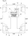
- this brake device includes left and right parking brake mechanisms 1L and 1R, and a control device 2 for controlling these parking brake mechanisms 1L and 1R.
- the left and right parking brake mechanisms 1L and 1R have, for example, a configuration in which wires 3 and 3 of so-called wire-type parking brakes are pulled by driving sources 4 and 4, such as electric motors or actuators, prepared separately for the left and right sides. Note that the left and right parking brake mechanisms 1L and 1R are not limited to such mechanisms.
- hydraulic or electric brake devices for example, are provided as service brakes 6 for braking left front, right front, left rear, and right rear wheels 5.
- the left and right parking brake mechanisms 1L and 1R are provided for the left and right rear wheels 5 and 5.
- the left and right parking brake mechanisms 1L and 1R may alternatively be provided for the left and right front wheels 5 and 5, or the left and right parking brake mechanisms 1L and 1R may alternatively be provided for the left and right wheels 5 and 5 on both front and rear sides.
- the parking brake mechanisms 1L and 1R are configured to independently apply braking forces to the left and right wheels 5 and 5, respectively, of the vehicle, and hold the vehicle stationary or at stoppage.
- each of the parking brake mechanisms 1L and 1R uses, for example, a brake rotor (not shown) and a friction pad (not shown) of the service brake 6, to apply the braking force.
- Each of the parking brake mechanisms 1L and 1R includes the driving source 4, a worm gear mechanism 7, the wire 3, and a brake shoe lever or a push rod/cam mechanism, which is not shown.
- the brake shoe lever is adopted.
- the push rod/cam mechanism includes a cam (not shown) connected to the wire 3, a push rod (not shown) pressed by a pressing force by this cam, and a piston (not shown) which increases the pressure of a pressing force from the push rod and transmits the increased pressure to the friction pad.
- the worm gear mechanism 7 includes a worm 8 on the driving side, a worm wheel 9 on the driven side, and a winding reel 10.
- the worm 8 is coupled to a motor shaft (not shown) of the electric motor, which is the driving source 4.
- the worm wheel 9 meshes with the worm 8, and a rotation of the worm wheel 9 causes the winding reel 10 to rotate. This rotation of the winding reel 10 causes the wire 3 to be wound up.
- Driving the electric motor to rotate in a predetermined rotation direction causes the wire 3 to be wound up through the worm 8, the worm wheel 9, and the winding reel 10.
- the worm wheel 9 is provided with a ratchet mechanism 11 to prevent the worm wheel 9 from rotating in a reverse direction even if the electric motor stops running or electricity stops passing through the electric motor. For example, if each of the parking brake mechanisms 1L and 1R is actuated to generate a braking force, the ratchet mechanism 11 prevents the braking force from being released even after main power of the vehicle is turned off. The vehicle is thus held stationary.
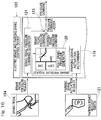
- Fig. 2 is a block diagram of a control system of this brake device.
- the control device 2 of this brake device includes a parking brake actuation determiner 12.
- the control device 2 is formed by a computer including a processor, a read-only memory (ROM) having a program to be executed by the processor, a random-access memory (RAM), and another electronic circuit, such as a co-processor.
- the parking brake actuation determiner 12 adjusts respective timings at which the left and right parking brake mechanisms 1L and 1R are actuated respectively to shift from an unlocked state to a parking lock state so as to reduce an uncomfortable feeling and annoyance caused to an occupant of the vehicle.
- the parking brake actuation determiner 12 When a driver desires to actuate the parking brake mechanisms 1L and 1R, the driver operates a parking brake request switch 13 provided on a console panel or the like of the vehicle, for example. A parking brake actuation request generated as a result is inputted to the parking brake actuation determiner 12. In the case where the left and right parking brake mechanisms 1L and 1R are actuated simultaneously, the parking brake actuation determiner 12 generates (left and right) parking brake actuation commands simultaneously for the left and right parking brake mechanisms 1L and 1R upon input of the parking brake actuation request, for example.
- the parking brake actuation determiner 12 includes a set time observer 14 and an actuation command suspending section 15.
- the set time observer 14 inputs the parking brake actuation command into one 1L (1R) of the left and right parking brake mechanisms 1L and 1R, and determines whether a set time has elapsed.
- the set time observer 14 includes a timer implemented in software or hardware, and a comparator that compares an output value of the timer with the set time, and outputs a result of the comparison.
- the set time is, for example, determined previously by a sensory evaluation or the like at the time of the design of the vehicle, and the simplest example thereof is a time from the generation of the parking brake actuation command for the one parking brake mechanism 1L (1R) to a completion of an operation of the one parking brake mechanism 1L (1R).
- the actuation command suspending section 15 includes a demultiplexer or the like implemented in software or hardware, for example, and, when the set time observer 14 has determined that the set time has elapsed, outputs the parking brake actuation command from the demultiplexer to input the parking brake actuation command into the other 1R (1L) of the left and right parking brake mechanisms 1L and 1R.
- the left and right parking brake mechanisms 1L and 1R are thus actuated one after the other in succession using the set time.
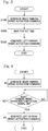
- Fig. 3 is a flowchart illustrating an example in which the left and right parking brake mechanisms in this brake device are actuated one after the other in time. The following description will be provided with appropriate reference made to Figs. 1 and 2 as well.
- the present control flow is started if the parking brake request switch 13 is pressed, and the parking brake actuation request is transmitted to the parking brake actuation determiner 12 (START). Note that, in the example described below, descriptions of a determination as to malfunctioning of the parking brake, a process related to a time limit at a waiting time for condition meeting, and so on, are omitted, and it is assumed that such determination and process are appropriately performed as necessary.
- the right parking brake mechanism 1R is actuated before the left parking brake mechanism 1L in the case where the left and right parking brake mechanisms 1L and 1R are actuated one after the other in succession, but it is to be noted that either one of the left and right parking brake mechanisms 1L and 1R may be actuated first.
- the parking brake actuation determiner 12 After the present procedure is started, upon input of the parking brake actuation request, the parking brake actuation determiner 12 generates the parking brake actuation command first for the right parking brake mechanism 1R to actuate the right parking brake mechanism 1R (step S100). Thereafter, the parking brake actuation determiner 12 waits for the set time of a given length set by the set time observer 14 (step S200). After the time of the given length has elapsed, that is, when the set time observer 14 has determined that the set time has elapsed, the actuation command suspending section 15 of the parking brake actuation determiner 12 generates the parking brake actuation command for the left parking brake mechanism 1L to actuate the left parking brake mechanism 1L (step S300). The present procedure is thereafter finished (END).
- the parking brake actuation determiner 12 in this case includes an operation completion signal monitor 16 and an actuation command sequential input section 17.
- the operation completion signal monitor 16 inputs the parking brake actuation command into one mechanism 1L (1R) of the left and right parking brake mechanisms 1L and 1R, and performs monitoring for an operation completion signal indicating a completion of the operation of the one mechanism 1L (1R) of the left and right parking brake mechanisms 1L and 1R.
- a specific example of a timing at which the operation completion signal for the parking brake mechanism 1L (1R) is outputted is a timing based on the fact that the driving source 4, such as the aforementioned electric motor or actuator, has completed a required amount of operation.
- the driving source 4 such as the aforementioned electric motor or actuator
- the operation completion signal monitor 16 is able to determine that the driving source 4 has completed the required amount of operation by using a predetermined comparison function, a transform function, and/or the like in a library or a lookup table (LUT), for example, and, when the electric current detected by the electric current sensor Sa is equal to or greater than a threshold value, by calculating and outputting a result of comparison between the value of the electric current and the threshold value.
- the threshold value is determined, for example, on the basis of a result of an experiment, a simulation, or the like.
- the above timing may be based on the fact that the driving source 4 has rotated by a minimum necessary angle determined as a result of an experiment, a simulation, or the like, with reference made to an angle measured by a rotation angle sensor attached to the winding reel or the like or by an angle sensor used on controlling the motor served as the driving source 4, for example.
- the actuation command sequential input section 17 inputs the parking brake actuation command into the other 1R (1L) of the left and right parking brake mechanisms 1L and 1R to actuate the other parking brake mechanism 1R (1L).
- the left and right parking brake mechanisms 1L and 1R are thus actuated one after the other in succession using the parking brake operation completion signal.
- Fig. 4 is a flowchart illustrating an example in which the parking brake operation completion signal is used in this brake device.
- the present procedure is started if the parking brake request switch 13 is pressed and the parking brake actuation request is transmitted to the parking brake actuation determiner 12 (START).
- the parking brake actuation determiner 12 Upon input of the parking brake actuation request, the parking brake actuation determiner 12 generates the parking brake actuation command first for the right parking brake mechanism 1R, also for the sake of description, to actuate the right parking brake mechanism 1R (step al).
- the operation completion signal monitor 16 waits until the parking brake operation completion signal is received from the right parking brake mechanism 1R (step a2). If the parking brake operation completion signal is not received (step a2: no), the procedure goes back to step a2. After receiving the parking brake operation completion signal from the right parking brake mechanism 1R (step a2: yes), the actuation command sequential input section 17 generates the parking brake actuation command for the left parking brake mechanism 1L to actuate the left parking brake mechanism 1L (step a3). The present procedure is thereafter finished (END).
- the control device 2 switches the state of each of the left and right parking brake mechanisms 1L and 1R from the unlocked state to the parking lock state in response to pressing of the parking brake request switch 13.
- the parking brake actuation determiner 12 of the control device 2 adjusts the timing at which each of the left and right parking brake mechanisms 1L and 1R is actuated. For example, such a process of reconfiguring the control flow of the control device 2 may be performed to reduce the uncomfortable feeling and annoyance due to the operating noise, which does not restrict the structure or arrangement of components as in related art. This leads to an improvement in versatility of the brake device.
- the uncomfortable feeling and annoyance due to the operating noise can be reduced by estimating, for example, the sound pressure level of the operating noise at the time of the design of the vehicle, and by actuating the left and right parking brake mechanisms 1L and 1R simultaneously or one after the other in succession in accordance with the operating noise. For example, when the sound pressure level of the operating noise is low, simultaneous actuation of the left and right parking brake mechanisms 1L and 1R does not lead to a high sound pressure level, and leads to shortening the duration of the operating noise, resulting in reductions in the uncomfortable feeling and annoyance.
- the left and right parking brake mechanisms 1L and 1R may be actuated simultaneously to shorten the durations of the operating noise and the vibration thereby to reduce the uncomfortable feeling and annoyance.
- the left and right parking brake mechanisms 1L and 1R may be actuated one after the other in succession to prevent the sound pressure level from having a high peak, so that the uncomfortable feeling and annoyance can be reduced.
- the left and right parking brake mechanisms 1L and 1R may be actuated one after the other in succession to reduce the operating noise and the amplitude of the vibration, so that the sound pressure level can be prevented from having a high peak, and the uncomfortable feeling and annoyance can be reduced.
- left and right parking brake mechanisms 1L and 1R each of which is formed by a driving source 4, such as an electric motor, may be provided directly on left and right service brakes 6 and 6, respectively.
- a brake device as a whole can be made compact, and the assemblability of this brake device to a vehicle is enhanced in comparison with the brake device according to the first embodiment.
- a direct-acting actuator or electric motor for example, may be used as the driving source 4 for each of the parking brake mechanisms 1L and 1R, and the brake shoe lever or the cam may be directly driven without use of the worm gear mechanism and the wire.
- the parking brake actuation determiner 12 may be configured to adjust both the timing at which each of the left and right parking brake mechanisms 1L and 1R is actuated and a timing at which a predetermined mechanism in the vehicle is actuated so as to reduce the uncomfortable feeling caused to the occupant of the vehicle.
- An example of the predetermined mechanism is a door lock mechanism (not shown).
- the timing at which the door lock mechanism is actuated and the timing at which each of the parking brake mechanisms 1L and 1R is actuated may be adjusted to reduce the uncomfortable feeling and annoyance caused by the actuation of the parking brake.
- this electric brake device includes left and right electric brake mechanisms 101L and 101R, left and right parking brake mechanisms 102L and 102R, and a control device (hereinafter referred to also as an "electric brake and parking brake control device") 103 that controls the electric brake mechanisms 101L and 101R and the parking brake mechanisms 102L and 102R.
- the left and right electric brake mechanisms 101L and 101R independently apply braking forces to left and right wheels 5 and 5 (see Fig. 9 ) of a vehicle, respectively in response to an operation of a brake pedal 104, which is a brake operation portion 104.
- the brake operation portion 104 is not limited to a pedal, but may alternatively be a button, a lever, or the like, as long as it is a means for an operator to give an instruction to apply a brake.
- the left and right electric brake mechanisms 101L and 101R are configured to be symmetrical or to have the same structure, and the left and right parking brake mechanisms 102L and 102R are also configured to be symmetrical or to have the same structure.
- the parking brake mechanisms 102L and 102R are fitted on the vehicle such that each one 102L (102R) of the parking brake mechanisms 102L and 102R is associated with corresponding one 101L (101R) of the electric brake mechanisms 101L and 101R.
- the left and right electric brake mechanisms 101L and 101R are provided for both the front and rear wheels, whereas the left and right parking brake mechanisms 102L and 102R are provided for either the rear wheels or the front wheels of the vehicle.
- the left and right parking brake mechanisms 102L and 102R may alternatively be provided for both the front and rear wheels.
- Each of the electric brake mechanisms 101L and 101R includes an electric motor 106, a speed reduction mechanism 107 for reducing the speed of rotation of the electric motor 106, a linear motion mechanism 108, a brake rotor 109, and a friction pad 110.
- the electric motor 106, the speed reduction mechanism 107, and the linear motion mechanism 108 are incorporated in a housing (not shown) or the like, for example.
- the speed reduction mechanism 107 transmits the rotation of the electric motor 106 to a third gear 112 fixed to a rotating shaft 111 with reduced speed, and includes a first gear 113, an intermediate gear 114, and the third gear 112.
- the speed reduction mechanism 107 according to this embodiment is configured to be capable of transmitting rotation of the first gear 113 which is fitted to a rotor shaft 106a of the electric motor 106, to the third gear 112 which is fixed to an end portion of the rotating shaft 111, with reduced speed via the intermediate gear 114 which has a two-stage configuration having integrated two gears with different numbers of teeth.
- the linear motion mechanism 108 converts a rotational motion outputted from the speed reduction mechanism 107 into a linear motion of a linearly moving portion 115, which is substantially cylindrical or columnar in shape, through a feed screw mechanism, to bring the friction pad 110 into or out of contact with the brake rotor 109.
- the linearly moving portion 115 is supported so as to be movable in an axial direction indicated by arrow A1 while being prevented from rotating.
- the friction pad 110 is disposed at an end of the linearly moving portion 115 on the outboard side (i.e., on the left or right side, with respect to the longitudinal center line, of the vehicle).
- the parking brake mechanism 102L (102R) is configured to be capable of switching between a parking lock state, in which the parking brake mechanism 102L (102R) prevents the braking force by the electric brake mechanism 101L (101R) from being released, and an unlocked state, in which the parking brake mechanism 102L (102R) permits the braking force to be released.
- the parking brake mechanism 102L (102R) includes a locking member 116 and an actuator 117 that drives the locking member 116 to switch the state thereof.
- Fig. 7A is a schematic diagram illustrating a main part of the parking brake mechanism in a plan view
- Fig. 7B is an enlarged sectional view illustrating a section of one of engagement holes 118 illustrated in Fig. 7A taken along a circumferential direction when viewed from the outboard side.
- a plurality of (six, in this embodiment) engagement holes 118 are formed at regular intervals in the circumferential direction.
- Each engagement hole 118 is formed in the shape of an oblong hole elongated in the circumferential direction.
- the locking member 116 is configured to be engaged with one of the engagement holes 118.
- Each engagement hole 118 includes a bottomed cylindrical hole portion 118a having a flat bottom, and a slanting hole portion 118b joined to the bottomed cylindrical hole portion 118a.
- the slanting hole portion 118b is shaped so as to slant to come closer to the outboard side thereof with increasing circumferential distance from a joint between the slanting hole portion 118b and the bottomed cylindrical hole portion 118a.
- a linear solenoid for example, is adopted as the actuator 117.
- the actuator 117 is configured to cause the locking member (a solenoid pin) 116 to advance out of the actuator 117 to be fitted into the bottomed cylindrical hole portion 118a of the engagement hole 118 formed in the intermediate gear 114 thereby to accomplish engagement of the locking member 116 with the engagement hole 118, so that rotation of the intermediate gear 114 is restrained, resulting in the parking lock state.
- a portion of the locking member 116 or the entire locking member 116 is caused to recede into the actuator 117 thereby to cause a disengagement thereof from the engagement hole 118, so that the rotation of the intermediate gear 114 is permitted, resulting in the unlocked state.
- the parking brake mechanism causes the electric brake mechanism 101L (101R) (see Fig. 6 ) to generate a pressing force greater than a required pressing force derived from a braking force necessary to stop the vehicle, and then actuates the actuator 117 to cause the locking member 116 to advance out of the actuator 117 as described above.
- the locking member 116 may not always come into engagement with any one of the engagement holes 118 formed in the intermediate gear 114. But, even if the locking member 116 does not come into engagement with the bottomed cylindrical hole portion 118a of any engagement hole 118, the locking member 116 will be fitted into and engaged with one of the engagement holes 118 in a manner described below.
- Fig. 8A is a schematic diagram illustrating a non-parking state lock which is in an off state of this electric brake device
- Fig. 8B is a schematic diagram illustrating the parking lock state of the electric brake device.
- the rotation of the intermediate gear 114 caused by pushing back the linearly moving portion 115 due to the reaction force causes the position of the locking member 116 and the phase (position) of the engagement hole 118 to meet, and causes the locking member 116 to be pressed against the one circumferential end 118aa of the bottomed cylindrical hole portion 118a to be engaged therewith, so that the necessary pressing force is prevented from being reduced.
- Fig. 9 is a block diagram of a control system for explaining a normal service brake operation and so on of this electric brake device.
- the control device 103 of this electric brake device includes basic control section 103a.
- the control device 103 is formed by a computer including a processor, a read-only memory (ROM) having a program to be executed by the processor, a random-access memory (RAM), and another electronic circuit, such as a co-processor.
- the basic control section 103a causes the electric motor 106 corresponding to each of the left and right electric brake mechanisms 101L and 101R to operate to cause the friction pad 110 to be pressed against the brake rotor 109 thereby to apply the braking force.
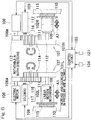
- Fig. 10 is a block diagram of the control system of this electric brake device, in which the brake operation portion 104 and the basic control section 103a shown in Fig. 9 are not shown for simpler illustration.
- the control device 103 of this electric brake device includes a parking brake actuation determiner 119 and left and right brake pressure generators 120L and 120R.
- the parking brake actuation determiner 119 adjusts the timing at which each of the parking brake mechanisms 102L and 102R is actuated to shift the state of the corresponding parking brake mechanism 102L or 102R from the unlocked state to the parking lock state, that is, adjusts a series of operations to be performed until the operation of each of the parking brake mechanisms 102L and 102R is completed.
- Operating the parking brake represents 1) generating a braking force, and 2) keeping the braking force and preventing the braking force from being released even if left uncontrolled.
- the "series of operations" mentioned above includes generating the braking force (i.e., increasing the pressing force), and keeping the generation of the pressing force (i.e., causing a mechanism for preventing a reverse rotation to function).
- the driver when the driver desires to actuate the parking brake mechanisms 102L and 102R, the driver operates the parking brake request switch 121 provided on a console panel or the like of the vehicle, for example.
- a parking brake actuation request generated as a result is inputted to the parking brake actuation determiner 119.
- the parking brake actuation determiner 119 In response to the input of the parking brake actuation request, the parking brake actuation determiner 119 according to this embodiment generates signals of left and right brake pressure request for the left and right brake pressure generators 120L and 120R, respectively.
- the left and right brake pressure generators 120L and 120R output left and right brake pressure commands, respectively. Each of the left and right brake pressure commands is replaced with a set pressing force.
- the left and right brake pressure commands are inputted to the left and right electric brake mechanisms 101L and 101R, respectively.
- the left and right electric brake mechanisms 101L and 101R drive the respective electric motors 106 to generate the pressing forces of the corresponding friction pads 110.
- the parking brake actuation determiner 119 detects feedback values of the left and right pressing forces. For example, the relationship between the pressing force and the electric current in the electric motor 106 is recorded beforehand in relationship setting portion (not shown).
- An electric current sensor Sa that detects the electric current in the electric motor 106 may be provided, and then, the parking brake actuation determiner 119 is able to compute the feedback value of each of the left and right pressing forces, for example, by applying the electric current detected by the electric current sensor Sa to the relationship setting portion, which is a predetermined comparison function, a transform function, and/or the like in a library or which is a lookup table (LUT).
- the relationship setting portion which is a predetermined comparison function, a transform function, and/or the like in a library or which is a lookup table (LUT).
- a load sensor (not shown) formed by a strain sensor or the like which detects the reaction force from the brake rotor 109 may alternatively be provided in each of the electric brake mechanisms 101L and 101R, and the parking brake actuation determiner 119 may be configured to obtain the feedback value by detecting the value detected by each load sensor, which is in direct proportion to the pressing force.
- the parking brake actuation determiner 119 compares the feedback value of each of the left and right pressing forces with a previously set pressing force (referred to as a pressing force threshold value) required when applying the parking brake. If the parking brake actuation determiner 119 determines that the feedback values of both the left and right pressing forces have exceeded the pressing force threshold value, the parking brake actuation determiner 119 generates a parking brake actuation command for each of the left and right parking brake mechanisms 102L and 102R.
- a process of reconfiguring the control flow of the control device 103 may be performed to reduce the uncomfortable feeling and annoyance due to the operating noise so that the structure or arrangement of the electric motor or the speed reduction mechanism is not restricted as in related art. This leads to an improvement in versatility of the electric brake device.
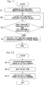
- Fig. 11 is a flowchart illustrating a procedure in which the control device of the electric brake device makes the left and right brake pressure requests simultaneously, and the left and right parking brake mechanisms are actuated simultaneously or one after the other in succession.
- the left and right parking brake mechanisms may be actuated simultaneously or one after the other in succession, as described below. The following description will be provided with appropriate reference made to Figs. 6 and 10 as well.
- the left and right brake pressure requests are signals inputted from the parking brake actuation determiner 119 to the left and right brake pressure generators 120L and 120R, respectively.
- the left and right brake pressure generators 120L and 120R output the brake pressure commands to the left and right electric brake mechanisms 101L and 101R, to cause the set pressing forces to be generated, respectively.
- the right parking brake mechanism 102R is actuated before the left parking brake mechanism 102L in the case where the left and right parking brake mechanisms 102L and 102R are actuated one after the other, but it is to be noted that either one of the left and right parking brake mechanisms 102L and 102R may be actuated first.
- the present procedure is started when the parking brake request switch 121 has been operated (START), and in response to the input of the parking brake actuation request, the parking brake actuation determiner 119 generates each of the left and right brake pressure requests (step S1).
- the left and right brake pressure generators 120L and 120R replace the left and right brake pressure commands, which are to be outputted, from a zero pressure command (i.e., a pressure command indicating a zero pressure) to a previously set pressure command required when applying the parking brake.
- the left and right brake pressure commands are inputted to the left and right electric brake mechanisms 101L and 101R, respectively.
- the left and right electric brake mechanisms 101L and 101R generate the pressing forces in accordance with the left and right brake pressure commands, respectively.
- the left and right pressing forces are outputted from the left and right electric brake mechanisms 101L and 101R as left and right pressure feedback values, respectively.
- the parking brake actuation determiner 119 obtains the left and right pressure feedback values by, for example, applying the electric current detected by the electric current sensors Sa to the relationship setting portion (step S2).
- the parking brake actuation determiner 119 compares each of the left and right pressure feedback values with the pressing force threshold value (step S3).
- the parking brake actuation determiner 119 determines that the feedback values of both the left and right pressing forces have exceeded the pressing force threshold value (step S3: yes)
- the parking brake actuation determiner 119 generates the parking brake actuation commands for the left and right parking brake mechanisms 102L and 102R at respective predetermined timings (step S4).
- the predetermined timings are, for example, timings of command generation which are determined by a test result to be able to reduce the sound pressure level perceived by the occupant of the vehicle, thus reducing the uncomfortable feeling and annoyance caused to the occupant.
- the predetermined timings are timings at which the left and right parking brake mechanisms 102L and 102R are actuated simultaneously, or timings at which the left and right parking brake mechanisms 102L and 102R are actuated one after the other in succession. The present procedure is thereafter finished.
- step S3 determines at step S3 that the feedback value of at least one of the left and right pressing forces does not exceed the pressing force threshold value (step S3: no)
- the procedure goes back to step S2
- the parking brake actuation determiner 119 calculates the feedback values of the left and right pressing forces again, and waits for both the feedback values to exceed the pressing force threshold value.
- step S3 although a description of a process (such as error handling) has been assumed to be omitted as mentioned above, error handling or the like may be additionally performed as necessary when the condition is not satisfied within a predetermined time.
- the parking brake actuation commands are generated for the left and right parking brake mechanisms 102L and 102R when step S4 is performed.
- Fig. 12 illustrates a procedure in the case where the parking brake actuation commands are to be generated for the left and the right one after the other in succession at step S4.
- the parking brake actuation determiner 119 first generates the parking brake actuation command for the right parking brake mechanism 102R (step S4-1).
- the parking brake actuation determiner 119 waits for a set time to accomplish the timing to reduce the uncomfortable feeling and annoyance (step S4-2).
- This set time is, for example, set on the basis of a result of an experiment, a simulation, or the like.
- the parking brake actuation determiner 119 generates the parking brake actuation command for the left parking brake mechanism 102L (step S4-3).
- the present procedure is thereafter finished (END).
- the other steps S1 to S3 omitted in Fig. 12 remain the same as in Fig. 11 .
- the steps S1 to S3 remain the same as in Fig. 11 .
- the parking brake actuation determiner 119 may use a parking brake operation completion signal for a condition for proceeding to the next control step.
- the parking brake operation completion signal is, for example, a signal based on the fact that one or both of the electric motor 106 and the actuator 117 have operated to a required extent.
- step S4 in Fig. 11 is replaced with steps S4-4 to S4-6 in Fig. 13 .
- the parking brake actuation determiner 119 generates the parking brake actuation command first for the right parking brake mechanism 102R (step S4-4), and waits for a detection of the parking brake operation completion signal of the right parking brake mechanism 102R (step S4-5). If the parking brake actuation determiner 119 detects the parking brake operation completion signal (step S4-5: yes), the parking brake actuation determiner 119 generates the parking brake actuation command for the remaining left parking brake mechanism 102L (step S4-6).
- the parking brake actuation determiner 119 In response to receipt of the parking brake actuation request, the parking brake actuation determiner 119 generates the right brake pressure request (step S5). In response to the right brake pressure request, the right brake pressure generator 120R replaces the right brake pressure command from the zero pressure command to the previously set pressure command required when applying the parking brake.
- the right brake pressure command is inputted to the right electric brake mechanism 101R, and the right electric brake mechanism 101R generates the pressing force in accordance with the right brake pressure command.
- the pressing force at this time is outputted as the right pressure feedback value, and the parking brake actuation determiner 119 detects the right pressure feedback value (step S6).
- the parking brake actuation determiner 119 compares the right pressure feedback value with the pressing force threshold value (step S7).
- step S7 If it is determined that the right pressure feedback value is equal to or less than the pressing force threshold value (step S7: no), the procedure goes back to step S6. If the parking brake actuation determiner 119 recognizes that the right pressure feedback value has exceeded the pressing force threshold value (step S7: yes), the parking brake actuation determiner 119 generates the left brake pressure request (step S8). In response to the left brake pressure request, the left brake pressure generator 120L replaces the left brake pressure command from the zero pressure command to the previously set pressure command required when applying the parking brake.
- the left electric brake mechanism 101L generates the pressing force in accordance with the left brake pressure command.
- the parking brake actuation determiner 119 detects the left pressure feedback value outputted from the left electric brake mechanism 101L (step S9).
- the parking brake actuation determiner 119 compares the left pressure feedback value with the pressing force threshold value (step S10). If it is determined that the left pressure feedback value is equal to or less than the pressing force threshold value (step S10: no), the procedure goes back to step S9.
- step S10 If the parking brake actuation determiner 119 recognizes that the left pressure feedback value has exceeded the pressing force threshold value (step S10: yes), the parking brake actuation determiner 119 generates the parking brake actuation commands for the left and right parking brake mechanisms 102L and 102R at the predetermined timings (step S11).
- the timings at which the left and right parking brake actuation commands are generated at this time are timings of command generation which are able to reduce the uncomfortable feeling and annoyance as described above.
- the present procedure is thereafter finished (END).
- the parking brake actuation determiner 119 In the case where the left and right parking brake actuation commands are to be generated simultaneously at step S11, the parking brake actuation determiner 119 generates the parking brake actuation commands for the left and right parking brake mechanisms 102L and 102R when step S11 is performed, as when step S4 is performed. In the case where the left and right parking brake actuation commands are to be generated one after the other in succession, steps S4-1 to S4-3 illustrated in Fig. 12 are similarly performed at step S11. In the case where the determination as to whether the locking member 116 of each of the parking brake mechanisms 102L and 102R has been engaged with any engagement hole 118 using the parking brake operation completion signal is added, step S11 is replaced with steps S4-4 to S4-6 in Fig. 13 .
- a method of arranging the operations in the order of 1) generating the right brake pressing force, 2) actuating the right parking brake, 3) generating the left brake pressing force, and 4) actuating the left parking brake or, in the case where operating noise occurs at the beginning of an increase in the pressing force, a method of arranging the operations in the order of 1) generating the right brake pressing force, 2) waiting for a predetermined time, 3) generating the left brake pressing force, and 4) comparing each of the left and right pressing forces with the pressing force threshold value.
- control blocks illustrated in Fig. 10 can be used to accomplish the required operations with a simple rearrangement of the control flow.
- This simple rearrangement means rearranging the order in which the steps are performed so that the steps will be performed in a required order, without changing the content of the process within each step.
- FIG. 15 is a block diagram of a control system of an electric brake device according to a modification of the third embodiment.
- a control device 103A of this electric brake device includes a parking brake actuation determiner 119 and left and right electric brake and parking brake control devices 122L and 122R.
- the electric brake and parking brake control devices 122L and 122R are provided with brake pressure generators 120L and 120R, respectively, and the parking brake actuation determiner 119 is provided outside of these electric brake and parking brake control devices 122L and 122R.
- the parking brake actuation determiner 119 is inside the electric brake and parking brake control device.
- the parking brake actuation determiner 119 may be either inside or outside the electric brake and parking brake control device, and there is no necessity for the parking brake actuation determiner 119 to be either inside or outside the electric brake and parking brake control device.
- each electric brake and parking brake control device 122L (122R) is configured to control one electric brake device
- the parking brake actuation determiner 119 be provided outside of the electric brake and parking brake control devices 122L and 122R. This is because a component that monitors the states of the left and right (i.e., two) electric brake mechanisms 101L and 101R and the left and right (i.e., two) parking brake mechanisms 102L and 102R simultaneously is necessary, and providing the parking brake actuation determiner 119 outside of the electric brake and parking brake control devices 122L and 122R allows a simpler configuration and greater practicality for centralized control over actuation timings.
- the parking brake actuation determiner 119 is provided inside any electric brake and parking brake control device
- one of the left and right electric brake and parking brake control devices needs to be configured to monitor both of the state simultaneously as described above, or the left and right electric brake and parking brake control devices need to be configured to communicate with each other and monitor the pressure feedback values therebetween to adjust each actuation timing therebetween, or one of the left and right electric brake and parking brake control devices needs to have the right of priority, as typified by a master-slave relation, and monitor the pressure feedback values through communication to determine each actuation timing.
- Adoption of such a configuration results in complicated control and configuration, and is not advantageous from the viewpoint of reducing an uncomfortable feeling and annoyance caused by operating noise.
- the control flow can exercise control still in a manner as described above.
- pieces of information such as the parking brake actuation commands and the feedback values of the pressing forces are exchanged between the parking brake actuation determiner 119 and the parking brake mechanisms 102L and 102R and the electric brake mechanisms 101L and 101R through the electric brake and parking brake control devices 122L and 122R.
- a practical method to realize the above is to connect each of the electric brake and parking brake control devices 122L and 122R with a higher-level integrated controller (not shown) of the vehicle and the parking brake actuation determiner 119 via intercommunication means, such as CAN bus communication, to allow necessary pieces of information to be transmitted and received collectively.
- intercommunication means such as CAN bus communication
- the parking brake actuation commands and the feedback values of the pressing forces may be exchanged directly between the parking brake actuation determiner 119 and the electric brake mechanisms 101L and 101R and the parking brake mechanisms 102L and 102R without intervention of the electric brake and parking brake control devices 122L and 122R.
- the feedback value of the pressing force is required when the electric brake is controlled, and in the case where collective transmission and reception of necessary pieces of information are possible, exchanging of the signals without the intervention of the electric brake and parking brake control devices 122L and 122R is probably inefficient.
- Fig. 16 illustrates another modification of the third embodiment, in which an electric brake and parking brake control device includes a parking brake actuation determiner 119, a brake pressure generator 120 (for a right brake in the example of Fig. 16 ), a brake pedal pressure command generator 124, and the pressure command adder 123.
- the brake pedal pressure command generator 124 generates a brake pedal pressure command on the basis of the brake pedal pressure request inputted through the brake pedal 104.
- the brake pedal pressure command is inputted to the pressure command adder 123.
- the parking brake actuation determiner 119 In response to receipt of a parking brake actuation request, the parking brake actuation determiner 119 generates a brake pressure request (for the right brake in the example of Fig. 16 ) at a predetermined timing.
- the brake pressure generator 120 inputs a required pressure command (referred to as a parking brake pressure command) into the pressure command adder 123.
- the pressure command adder 123 adds the above-mentioned two pressure commands together, and outputs the result as a total pressure command.
- the pressure command adder 123 may be replaced with a pressure command selector.
- the pressure command selector can take the place of the pressure command adder 123, and is configured to select the greater one of the two inputted pressure commands, and output the greater pressure command as the total pressure command.
- pressing the brake pedal will immediately increase the braking force and can prevent the vehicle from rolling backward.
- a brake locking may result with a high probability.
- the pressure command selector In the case where the pressure command selector is used, and in the case where a high pressing force is generated at the time of the parking brake, the pressure does not change until a pedal travel that generates a command value that exceeds a command value thereof is reached, and a reaction to the rolling backward of the vehicle may be delayed.
- the relationship between the pedal travel and the pressing force remains the same as that at the time of normal driving, the likelihood of a brake locking can be reduced to a low level.
- Fig. 17 illustrates a specific configuration according to yet another modification of the third embodiment. This control flow has been configured on the basis of the viewpoint that it is not necessary to manage the timing of the generation of the noise that is made when the pressing force is increased.
- the control flow is substantially equivalent to that of Fig. 11 .
- Signal flow is changed in relation to a brake pressure generator 120.
- a parking brake actuation request is directly inputted to the brake pressure generator 120, and both left and right parking brake pressure commands are immediately replaced from a zero pressure command to a previously set pressure command required when applying a parking brake respectively.
- the processes subsequent to step S1 of Fig. 11 remain substantially the same as when the control flow of Fig. 11 is performed using the control blocks of Fig. 10 .
- the timing of command generation may be adjusted so that the operating noise due to the actuation of the parking brake will occur simultaneously therewith. Even in this case, the uncomfortable feeling and annoyance due to the actuation of the parking brake can be reduced.
Landscapes
- Engineering & Computer Science (AREA)
- Mechanical Engineering (AREA)
- Transportation (AREA)
- General Engineering & Computer Science (AREA)
- Regulating Braking Force (AREA)
- Braking Systems And Boosters (AREA)
- Valves And Accessory Devices For Braking Systems (AREA)
Claims (8)
- Un dispositif de freinage comprenant : des mécanismes de frein de stationnement gauche et droit (1L, 1R) configurés pour appliquer indépendamment des forces de freinage aux roues gauche et droite (5) d'un véhicule, respectivement, et maintenir le véhicule immobile; et un dispositif de commande (2) configuré pour commander ces mécanismes de frein de stationnement (1L, 1R),
le dispositif de commande comprenant un dispositif de détermination de l'actionnement du frein de stationnement (12) configuré pour ajuster les moments respectifs auxquels les mécanismes de frein de stationnement gauche et droit (1L, 1R) sont actionnés afin de réduire une sensation d'inconfort causée à un occupant du véhicule,
dans lequel le déterminant de l'actionnement du frein de stationnement (12) comprend :un moniteur de signal de fin d'opération (16) configuré pour entrer une commande d'actionnement du frein de stationnement dans l'un des mécanismes de frein de stationnement gauche et droit (1L, 1R), et effectuer la surveillance d'un signal de fin d'opération indiquant la fin d'une opération de l'un des mécanismes de frein de stationnement gauche et droit (1L, 1R); etune section d'entrée séquentielle de commande d'actionnement configurée pour entrer une commande d'actionnement du frein de stationnement dans l'autre des mécanismes de frein de stationnement gauche et droit (1L, 1R) en réponse à une détection du signal de fin d'opération par le moniteur de signal de fin d'opération (16). - Le dispositif de freinage selon la revendication 1, dans lequel, en réponse à l'entrée d'une demande d'actionnement du frein de stationnement émanant d'un conducteur du véhicule, le dispositif de détermination de l'actionnement du frein de stationnement (12) entre une commande d'actionnement du frein de stationnement dans chacun des mécanismes de frein de stationnement gauche et droit (1L, 1R) sur la base d'une temporisation déterminée pour réduire la sensation d'inconfort causée à l'occupant du véhicule, afin d'amener ainsi le véhicule à entrer dans un état de verrouillage du stationnement dans lequel le véhicule est maintenu immobile.
- Le dispositif de freinage selon la revendication 1 ou 2, comprenant en outre des mécanismes de freinage électrique gauche et droit (101L, 101R) configurés pour être capables d'appliquer indépendamment des forces de freinage aux roues gauche et droite (5), respectivement, et pour être actionnés par un conducteur par l'intermédiaire d'une partie d'actionnement de frein, dans lequel
chacun des mécanismes de frein de stationnement gauche et droit (102L, 102R) est capable de commuter indépendamment entre un état de verrouillage de stationnement, dans lequel le mécanisme de frein de stationnement (102L, 102R) empêche, par un mécanisme correspondant des mécanismes de frein électrique gauche et droit (101L, 101R), la force de freinage d'être libérée, et un état déverrouillé, dans lequel le mécanisme de frein de stationnement (102L, 102R) permet à la force de freinage d'être libérée,
le dispositif de commande contrôle les mécanismes de freinage électrique gauche et droit (101L, 101R) et les mécanismes de freinage de stationnement gauche et droit (102L, 102R), et
le dispositif de détermination de l'actionnement du frein de stationnement (119) ajuste les moments respectifs auxquels les mécanismes de frein de stationnement gauche et droit (102L, 102R) sont actionnés pour passer de l'état déverrouillé à l'état de verrouillage du stationnement afin de réduire la sensation d'inconfort causée à l'occupant du véhicule. - Le dispositif de freinage selon la revendication 3, dans lequel chaque mécanisme de freinage électrique (101L, 101R) comprend un moteur électrique (106), un rotor de frein (109), une plaquette de friction (110) mise en contact avec le rotor de frein (109) pour générer la force de freinage, un mécanisme de réduction de vitesse (107) configuré pour réduire une vitesse de rotation du moteur électrique (106), et un mécanisme de mouvement linéaire (108) configuré pour convertir un mouvement de rotation produit par le mécanisme de réduction de vitesse en un mouvement linéaire de la plaquette de friction (110); et
chaque mécanisme de frein de stationnement (102L, 102R) comprend :un élément de verrouillage (116) devant être engagé dans un trou d'engagement (118) défini dans le mécanisme de réduction de la vitesse (107); etun actionneur (117) configuré pour entraîner l'élément de verrouillage (116) de manière à commuter entre l'état de verrouillage de stationnement, dans lequel l'élément de verrouillage (116) est engagé dans le trou d'engagement pour limiter le mouvement de rotation du mécanisme de réduction de vitesse (107), et l'état déverrouillé, dans lequel l'élément de verrouillage (116) est hors d'engagement avec le trou d'engagement (118). - Le dispositif de freinage selon la revendication 3, dans lequel le dispositif de commande comprend des générateurs de pression de freinage gauche et droit (120L, 120R) configurés pour délivrer des commandes de pression de freinage aux mécanismes de freinage électrique gauche et droit (101L, 102L), respectivement, pour amener les mécanismes de freinage électrique gauche et droit (101L, 102L) à générer une force de pression définie, en réponse à l'entrée d'un signal de demande de pression de freinage provenant du dispositif de détermination de l'actionnement du frein de stationnement (119).
- Le dispositif de freinage selon la revendication 5, dans lequel, en réponse à l'entrée d'une demande d'actionnement du frein de stationnement, le dispositif de détermination de l'actionnement du frein de stationnement (119) génère le signal de demande de pression de freinage pour chacun des générateurs de pression de freinage gauche et droit (120L, 120R) sur la base d'une temporisation définie.
- Le dispositif de freinage selon la revendication 5, dans lequel le dispositif de détermination de l'actionnement du frein de stationnement (119) surveille une valeur de rétroaction d'une force de pression générée par chaque mécanisme de freinage électrique (101L, 102L) après avoir émis le signal de demande de pression de freinage pour chacun des générateurs de pression de freinage gauche et droit (120L, 120R), et, lorsque la force de pression a dépassé une valeur seuil, génère une commande d'actionnement du frein de stationnement pour chacun des mécanismes de frein de stationnement gauche et droit (102L, 102R) sur la base d'une temporisation définie pour faire entrer chacun des mécanismes de frein de stationnement gauche et droit (102L, 102R) dans l'état de verrouillage de stationnement.
- Le dispositif de freinage selon la revendication 5, dans lequel
après avoir émis le signal de demande de pression de frein pour chacun des générateurs de pression de frein gauche et droit (120L, 120R), le dispositif de détermination de l'actionnement du frein de stationnement (119) génère une commande d'actionnement du frein de stationnement pour chacun des mécanismes de frein de stationnement gauche et droit (102L, 102R) afin d'amener chacun des mécanismes de frein de stationnement gauche et droit (102L, 102R) à entrer en état de verrouillage de stationnement, conformément à une condition prédéterminée; et
le dispositif de détermination de l'actionnement du frein de stationnement (119) émet les signaux de demande de pression de freinage respectifs pour les générateurs de pression de freinage gauche et droit (120L, 120R) et les commandes d'actionnement du frein de stationnement respectives pour les mécanismes de frein de stationnement gauche et droit (102L, 102R) sur la base de temporisations définies.
Applications Claiming Priority (3)
| Application Number | Priority Date | Filing Date | Title |
|---|---|---|---|
| JP2014088478A JP6377397B2 (ja) | 2014-04-22 | 2014-04-22 | パーキングブレーキ装置 |
| JP2014088477A JP6393069B2 (ja) | 2014-04-22 | 2014-04-22 | パーキングブレーキ付き電動ブレーキ装置 |
| PCT/JP2015/061402 WO2015163179A1 (fr) | 2014-04-22 | 2015-04-13 | Dispositif de frein |
Publications (3)
| Publication Number | Publication Date |
|---|---|
| EP3135548A1 EP3135548A1 (fr) | 2017-03-01 |
| EP3135548A4 EP3135548A4 (fr) | 2017-12-06 |
| EP3135548B1 true EP3135548B1 (fr) | 2020-12-02 |
Family
ID=54332346
Family Applications (1)
| Application Number | Title | Priority Date | Filing Date |
|---|---|---|---|
| EP15783276.7A Not-in-force EP3135548B1 (fr) | 2014-04-22 | 2015-04-13 | Dispositif de frein |
Country Status (4)
| Country | Link |
|---|---|
| US (1) | US10247268B2 (fr) |
| EP (1) | EP3135548B1 (fr) |
| CN (1) | CN106458174B (fr) |
| WO (1) | WO2015163179A1 (fr) |
Families Citing this family (8)
| Publication number | Priority date | Publication date | Assignee | Title |
|---|---|---|---|---|
| JP2018144576A (ja) * | 2017-03-03 | 2018-09-20 | Ntn株式会社 | 車両制御装置 |
| JP7222233B2 (ja) * | 2018-11-30 | 2023-02-15 | 株式会社アドヴィックス | 制動制御装置 |
| CN110173526A (zh) * | 2019-05-16 | 2019-08-27 | 广东机电职业技术学院 | 一种新型结构制动器 |
| FR3099903B1 (fr) * | 2019-08-12 | 2021-07-16 | Psa Automobiles Sa | Dispositif de frein de parking de vehicule automobile muni d'un systeme d'amortissement des chocs |
| CN110525401A (zh) * | 2019-08-15 | 2019-12-03 | 芜湖伯特利汽车安全系统股份有限公司 | 一种提升车辆制动舒适性的方法 |
| US12227157B2 (en) * | 2021-10-01 | 2025-02-18 | Ford Global Technologies, Llc | Methods and apparatus to extend brake life cycle |
| DE102022204631A1 (de) | 2022-05-11 | 2023-11-16 | Volkswagen Aktiengesellschaft | Wärmebereitstellung bei einem stehenden Elektrofahrzeug |
| CN114954412B (zh) * | 2022-05-31 | 2023-08-22 | 上海三一重机股份有限公司 | 驻车故障检测方法、装置、系统及作业机械 |
Family Cites Families (16)
| Publication number | Priority date | Publication date | Assignee | Title |
|---|---|---|---|---|
| JPH06286596A (ja) | 1993-03-31 | 1994-10-11 | Toyota Motor Corp | アンチロック型液圧ブレーキ装置 |
| CN1098055A (zh) * | 1993-03-31 | 1995-02-01 | 丰田自动车株式会社 | 车辆制动压力控制机构 |
| JPH06286595A (ja) | 1993-03-31 | 1994-10-11 | Toyota Motor Corp | 車輪過大スリップ防止装置 |
| US20070084682A1 (en) * | 2001-07-31 | 2007-04-19 | Griffith T T | Parking brake adjustment for an aircraft having an electric brake system |
| JP3945387B2 (ja) * | 2002-11-26 | 2007-07-18 | 株式会社日立製作所 | 電動ブレーキ,その制御装置及び電動ブレーキの制御方法 |
| JP4370775B2 (ja) * | 2002-12-17 | 2009-11-25 | 日産自動車株式会社 | 複合ブレーキの協調制御装置 |
| JP2005017453A (ja) * | 2003-06-24 | 2005-01-20 | Murata Mach Ltd | 画像形成装置 |
| JP4680643B2 (ja) | 2005-03-18 | 2011-05-11 | 本田技研工業株式会社 | 車両の電動パーキングブレーキシステム |
| DE202007017096U1 (de) * | 2007-12-05 | 2008-02-14 | Edscha Ag | Kraftfahrzeug-Feststellbremse |
| JP2009149209A (ja) * | 2007-12-20 | 2009-07-09 | Toyota Motor Corp | ワイパ装置及びワイパ用モータ駆動方法 |
| DE102010003232A1 (de) * | 2009-04-06 | 2010-10-07 | Continental Teves Ag & Co. Ohg | Verfahren zum Betreiben einer Bremsanlage, Bremsanlage und Kraftfahrzeug |
| JP2010241271A (ja) | 2009-04-06 | 2010-10-28 | Toyota Motor Corp | ブレーキ制御装置 |
| JP2012193802A (ja) | 2011-03-17 | 2012-10-11 | Akebono Brake Ind Co Ltd | パーキング機構付電動式ブレーキ装置 |
| JP5923969B2 (ja) | 2011-12-22 | 2016-05-25 | 株式会社アドヴィックス | 電動パーキングブレーキ装置 |
| JP5834993B2 (ja) * | 2012-02-20 | 2015-12-24 | 日産自動車株式会社 | 車両のパークロック装置 |
| JP5964701B2 (ja) * | 2012-08-31 | 2016-08-03 | 日立オートモティブシステムズ株式会社 | ブレーキ装置 |
-
2015
- 2015-04-13 EP EP15783276.7A patent/EP3135548B1/fr not_active Not-in-force
- 2015-04-13 CN CN201580020709.0A patent/CN106458174B/zh not_active Expired - Fee Related
- 2015-04-13 WO PCT/JP2015/061402 patent/WO2015163179A1/fr not_active Ceased
-
2016
- 2016-10-18 US US15/296,492 patent/US10247268B2/en not_active Expired - Fee Related
Non-Patent Citations (1)
| Title |
|---|
| None * |
Also Published As
| Publication number | Publication date |
|---|---|
| US20170037919A1 (en) | 2017-02-09 |
| EP3135548A1 (fr) | 2017-03-01 |
| CN106458174A (zh) | 2017-02-22 |
| WO2015163179A1 (fr) | 2015-10-29 |
| US10247268B2 (en) | 2019-04-02 |
| CN106458174B (zh) | 2019-05-28 |
| EP3135548A4 (fr) | 2017-12-06 |
Similar Documents
| Publication | Publication Date | Title |
|---|---|---|
| EP3135548B1 (fr) | Dispositif de frein | |
| US10081345B2 (en) | Electric brake system | |
| EP3741634B1 (fr) | Contrôle de frein de parking électrique réparti | |
| JP6408585B2 (ja) | フェールセーフティと利用性の向上した運転アシストシステム | |
| US10442413B2 (en) | Brake control apparatus | |
| US20200049215A1 (en) | Brake actuator and electromechanical brake using the same and control method thereof | |
| US11092236B2 (en) | Vehicle control device | |
| KR20180080303A (ko) | 준탄성 해제 단부 정지부를 사용하여 신뢰 가능한 방식으로 전기 작동기를 해제하기 위한 방법 및 디바이스 | |
| US11112008B2 (en) | Vehicle control device | |
| US10308229B2 (en) | Electronic control brake system and method for controlling the same | |
| US10507810B2 (en) | Electric brake device | |
| JP2015193357A (ja) | 電動式ブレーキシステム、電動式ブレーキシステムを搭載した車両、及び電動式ブレーキシステムの制御方法 | |
| JP2015029392A (ja) | ブレーキ制御装置 | |
| JP2019038302A (ja) | 電動ブレーキ装置 | |
| JP2017171215A (ja) | ブレーキシステム | |
| EP2873575B1 (fr) | Système de freinage de véhicule présentant un frein à friction et un freinage par récupération et son procédé de fonctionnement | |
| JP6393069B2 (ja) | パーキングブレーキ付き電動ブレーキ装置 | |
| JP6377397B2 (ja) | パーキングブレーキ装置 | |
| KR20230042338A (ko) | 브레이크 장치 | |
| JP2017043357A (ja) | 電動ブレーキシステム | |
| EP4119811B1 (fr) | Dispositif de frein de stationnement électrique | |
| JP7526254B2 (ja) | 電動パーキングブレーキ装置 | |
| JP6173971B2 (ja) | 車両の制動システム | |
| JP2017100645A (ja) | 車両の電動制動装置 | |
| KR20150124692A (ko) | 전자식 주차 브레이크 시스템 및 그 제어방법 |
Legal Events
| Date | Code | Title | Description |
|---|---|---|---|
| STAA | Information on the status of an ep patent application or granted ep patent |
Free format text: STATUS: THE INTERNATIONAL PUBLICATION HAS BEEN MADE |
|
| PUAI | Public reference made under article 153(3) epc to a published international application that has entered the european phase |
Free format text: ORIGINAL CODE: 0009012 |
|
| STAA | Information on the status of an ep patent application or granted ep patent |
Free format text: STATUS: REQUEST FOR EXAMINATION WAS MADE |
|
| 17P | Request for examination filed |
Effective date: 20161026 |
|
| AK | Designated contracting states |
Kind code of ref document: A1 Designated state(s): AL AT BE BG CH CY CZ DE DK EE ES FI FR GB GR HR HU IE IS IT LI LT LU LV MC MK MT NL NO PL PT RO RS SE SI SK SM TR |
|
| AX | Request for extension of the european patent |
Extension state: BA ME |
|
| DAV | Request for validation of the european patent (deleted) | ||
| DAX | Request for extension of the european patent (deleted) | ||
| A4 | Supplementary search report drawn up and despatched |
Effective date: 20171107 |
|
| RIC1 | Information provided on ipc code assigned before grant |
Ipc: F16D 125/48 20120101ALI20171030BHEP Ipc: F16D 125/40 20120101ALI20171030BHEP Ipc: F16D 129/08 20120101ALI20171030BHEP Ipc: B60T 7/10 20060101ALI20171030BHEP Ipc: B60T 8/17 20060101AFI20171030BHEP Ipc: F16D 127/06 20120101ALI20171030BHEP Ipc: B60T 13/74 20060101ALI20171030BHEP Ipc: F16D 121/24 20120101ALI20171030BHEP Ipc: F16D 65/18 20060101ALI20171030BHEP |
|
| GRAP | Despatch of communication of intention to grant a patent |
Free format text: ORIGINAL CODE: EPIDOSNIGR1 |
|
| STAA | Information on the status of an ep patent application or granted ep patent |
Free format text: STATUS: GRANT OF PATENT IS INTENDED |
|
| RIC1 | Information provided on ipc code assigned before grant |
Ipc: F16D 65/18 20060101ALI20200527BHEP Ipc: B60T 7/10 20060101ALI20200527BHEP Ipc: F16D 125/40 20120101ALI20200527BHEP Ipc: F16D 121/24 20120101ALI20200527BHEP Ipc: F16D 127/06 20120101ALI20200527BHEP Ipc: F16D 125/48 20120101ALI20200527BHEP Ipc: B60T 8/17 20060101AFI20200527BHEP Ipc: B60T 13/74 20060101ALI20200527BHEP Ipc: F16D 129/08 20120101ALI20200527BHEP |
|
| INTG | Intention to grant announced |
Effective date: 20200619 |
|
| GRAS | Grant fee paid |
Free format text: ORIGINAL CODE: EPIDOSNIGR3 |
|
| GRAA | (expected) grant |
Free format text: ORIGINAL CODE: 0009210 |
|
| STAA | Information on the status of an ep patent application or granted ep patent |
Free format text: STATUS: THE PATENT HAS BEEN GRANTED |
|
| AK | Designated contracting states |
Kind code of ref document: B1 Designated state(s): AL AT BE BG CH CY CZ DE DK EE ES FI FR GB GR HR HU IE IS IT LI LT LU LV MC MK MT NL NO PL PT RO RS SE SI SK SM TR |
|
| REG | Reference to a national code |
Ref country code: GB Ref legal event code: FG4D |
|
| REG | Reference to a national code |
Ref country code: AT Ref legal event code: REF Ref document number: 1340587 Country of ref document: AT Kind code of ref document: T Effective date: 20201215 Ref country code: CH Ref legal event code: EP |
|
| REG | Reference to a national code |
Ref country code: IE Ref legal event code: FG4D |
|
| REG | Reference to a national code |
Ref country code: DE Ref legal event code: R096 Ref document number: 602015062939 Country of ref document: DE |
|
| PG25 | Lapsed in a contracting state [announced via postgrant information from national office to epo] |
Ref country code: RS Free format text: LAPSE BECAUSE OF FAILURE TO SUBMIT A TRANSLATION OF THE DESCRIPTION OR TO PAY THE FEE WITHIN THE PRESCRIBED TIME-LIMIT Effective date: 20201202 Ref country code: FI Free format text: LAPSE BECAUSE OF FAILURE TO SUBMIT A TRANSLATION OF THE DESCRIPTION OR TO PAY THE FEE WITHIN THE PRESCRIBED TIME-LIMIT Effective date: 20201202 Ref country code: NO Free format text: LAPSE BECAUSE OF FAILURE TO SUBMIT A TRANSLATION OF THE DESCRIPTION OR TO PAY THE FEE WITHIN THE PRESCRIBED TIME-LIMIT Effective date: 20210302 Ref country code: GR Free format text: LAPSE BECAUSE OF FAILURE TO SUBMIT A TRANSLATION OF THE DESCRIPTION OR TO PAY THE FEE WITHIN THE PRESCRIBED TIME-LIMIT Effective date: 20210303 |
|
| PGFP | Annual fee paid to national office [announced via postgrant information from national office to epo] |
Ref country code: FR Payment date: 20210224 Year of fee payment: 7 |
|
| REG | Reference to a national code |
Ref country code: NL Ref legal event code: MP Effective date: 20201202 |
|
| REG | Reference to a national code |
Ref country code: AT Ref legal event code: MK05 Ref document number: 1340587 Country of ref document: AT Kind code of ref document: T Effective date: 20201202 |
|
| PG25 | Lapsed in a contracting state [announced via postgrant information from national office to epo] |
Ref country code: PL Free format text: LAPSE BECAUSE OF FAILURE TO SUBMIT A TRANSLATION OF THE DESCRIPTION OR TO PAY THE FEE WITHIN THE PRESCRIBED TIME-LIMIT Effective date: 20201202 Ref country code: SE Free format text: LAPSE BECAUSE OF FAILURE TO SUBMIT A TRANSLATION OF THE DESCRIPTION OR TO PAY THE FEE WITHIN THE PRESCRIBED TIME-LIMIT Effective date: 20201202 Ref country code: LV Free format text: LAPSE BECAUSE OF FAILURE TO SUBMIT A TRANSLATION OF THE DESCRIPTION OR TO PAY THE FEE WITHIN THE PRESCRIBED TIME-LIMIT Effective date: 20201202 Ref country code: BG Free format text: LAPSE BECAUSE OF FAILURE TO SUBMIT A TRANSLATION OF THE DESCRIPTION OR TO PAY THE FEE WITHIN THE PRESCRIBED TIME-LIMIT Effective date: 20210302 |
|
| PG25 | Lapsed in a contracting state [announced via postgrant information from national office to epo] |
Ref country code: NL Free format text: LAPSE BECAUSE OF FAILURE TO SUBMIT A TRANSLATION OF THE DESCRIPTION OR TO PAY THE FEE WITHIN THE PRESCRIBED TIME-LIMIT Effective date: 20201202 Ref country code: HR Free format text: LAPSE BECAUSE OF FAILURE TO SUBMIT A TRANSLATION OF THE DESCRIPTION OR TO PAY THE FEE WITHIN THE PRESCRIBED TIME-LIMIT Effective date: 20201202 |
|
| REG | Reference to a national code |
Ref country code: LT Ref legal event code: MG9D |
|
| PG25 | Lapsed in a contracting state [announced via postgrant information from national office to epo] |
Ref country code: LT Free format text: LAPSE BECAUSE OF FAILURE TO SUBMIT A TRANSLATION OF THE DESCRIPTION OR TO PAY THE FEE WITHIN THE PRESCRIBED TIME-LIMIT Effective date: 20201202 Ref country code: SK Free format text: LAPSE BECAUSE OF FAILURE TO SUBMIT A TRANSLATION OF THE DESCRIPTION OR TO PAY THE FEE WITHIN THE PRESCRIBED TIME-LIMIT Effective date: 20201202 Ref country code: PT Free format text: LAPSE BECAUSE OF FAILURE TO SUBMIT A TRANSLATION OF THE DESCRIPTION OR TO PAY THE FEE WITHIN THE PRESCRIBED TIME-LIMIT Effective date: 20210405 Ref country code: RO Free format text: LAPSE BECAUSE OF FAILURE TO SUBMIT A TRANSLATION OF THE DESCRIPTION OR TO PAY THE FEE WITHIN THE PRESCRIBED TIME-LIMIT Effective date: 20201202 Ref country code: EE Free format text: LAPSE BECAUSE OF FAILURE TO SUBMIT A TRANSLATION OF THE DESCRIPTION OR TO PAY THE FEE WITHIN THE PRESCRIBED TIME-LIMIT Effective date: 20201202 Ref country code: CZ Free format text: LAPSE BECAUSE OF FAILURE TO SUBMIT A TRANSLATION OF THE DESCRIPTION OR TO PAY THE FEE WITHIN THE PRESCRIBED TIME-LIMIT Effective date: 20201202 Ref country code: SM Free format text: LAPSE BECAUSE OF FAILURE TO SUBMIT A TRANSLATION OF THE DESCRIPTION OR TO PAY THE FEE WITHIN THE PRESCRIBED TIME-LIMIT Effective date: 20201202 |
|
| PGFP | Annual fee paid to national office [announced via postgrant information from national office to epo] |
Ref country code: DE Payment date: 20210226 Year of fee payment: 7 |
|
| PG25 | Lapsed in a contracting state [announced via postgrant information from national office to epo] |
Ref country code: AT Free format text: LAPSE BECAUSE OF FAILURE TO SUBMIT A TRANSLATION OF THE DESCRIPTION OR TO PAY THE FEE WITHIN THE PRESCRIBED TIME-LIMIT Effective date: 20201202 |
|
| REG | Reference to a national code |
Ref country code: DE Ref legal event code: R097 Ref document number: 602015062939 Country of ref document: DE |
|
| PG25 | Lapsed in a contracting state [announced via postgrant information from national office to epo] |
Ref country code: IS Free format text: LAPSE BECAUSE OF FAILURE TO SUBMIT A TRANSLATION OF THE DESCRIPTION OR TO PAY THE FEE WITHIN THE PRESCRIBED TIME-LIMIT Effective date: 20210402 |
|
| PLBE | No opposition filed within time limit |
Free format text: ORIGINAL CODE: 0009261 |
|
| STAA | Information on the status of an ep patent application or granted ep patent |
Free format text: STATUS: NO OPPOSITION FILED WITHIN TIME LIMIT |
|
| PG25 | Lapsed in a contracting state [announced via postgrant information from national office to epo] |
Ref country code: IT Free format text: LAPSE BECAUSE OF FAILURE TO SUBMIT A TRANSLATION OF THE DESCRIPTION OR TO PAY THE FEE WITHIN THE PRESCRIBED TIME-LIMIT Effective date: 20201202 Ref country code: AL Free format text: LAPSE BECAUSE OF FAILURE TO SUBMIT A TRANSLATION OF THE DESCRIPTION OR TO PAY THE FEE WITHIN THE PRESCRIBED TIME-LIMIT Effective date: 20201202 |
|
| 26N | No opposition filed |
Effective date: 20210903 |
|
| PG25 | Lapsed in a contracting state [announced via postgrant information from national office to epo] |
Ref country code: SI Free format text: LAPSE BECAUSE OF FAILURE TO SUBMIT A TRANSLATION OF THE DESCRIPTION OR TO PAY THE FEE WITHIN THE PRESCRIBED TIME-LIMIT Effective date: 20201202 Ref country code: MC Free format text: LAPSE BECAUSE OF FAILURE TO SUBMIT A TRANSLATION OF THE DESCRIPTION OR TO PAY THE FEE WITHIN THE PRESCRIBED TIME-LIMIT Effective date: 20201202 Ref country code: DK Free format text: LAPSE BECAUSE OF FAILURE TO SUBMIT A TRANSLATION OF THE DESCRIPTION OR TO PAY THE FEE WITHIN THE PRESCRIBED TIME-LIMIT Effective date: 20201202 Ref country code: ES Free format text: LAPSE BECAUSE OF FAILURE TO SUBMIT A TRANSLATION OF THE DESCRIPTION OR TO PAY THE FEE WITHIN THE PRESCRIBED TIME-LIMIT Effective date: 20201202 |
|
| GBPC | Gb: european patent ceased through non-payment of renewal fee |
Effective date: 20210413 |
|
| PG25 | Lapsed in a contracting state [announced via postgrant information from national office to epo] |
Ref country code: LU Free format text: LAPSE BECAUSE OF NON-PAYMENT OF DUE FEES Effective date: 20210413 |
|
| REG | Reference to a national code |
Ref country code: BE Ref legal event code: MM Effective date: 20210430 |
|
| PG25 | Lapsed in a contracting state [announced via postgrant information from national office to epo] |
Ref country code: CH Free format text: LAPSE BECAUSE OF NON-PAYMENT OF DUE FEES Effective date: 20210430 Ref country code: LI Free format text: LAPSE BECAUSE OF NON-PAYMENT OF DUE FEES Effective date: 20210430 Ref country code: GB Free format text: LAPSE BECAUSE OF NON-PAYMENT OF DUE FEES Effective date: 20210413 |
|
| PG25 | Lapsed in a contracting state [announced via postgrant information from national office to epo] |
Ref country code: IE Free format text: LAPSE BECAUSE OF NON-PAYMENT OF DUE FEES Effective date: 20210413 |
|
| PG25 | Lapsed in a contracting state [announced via postgrant information from national office to epo] |
Ref country code: IS Free format text: LAPSE BECAUSE OF FAILURE TO SUBMIT A TRANSLATION OF THE DESCRIPTION OR TO PAY THE FEE WITHIN THE PRESCRIBED TIME-LIMIT Effective date: 20210402 |
|
| PG25 | Lapsed in a contracting state [announced via postgrant information from national office to epo] |
Ref country code: BE Free format text: LAPSE BECAUSE OF NON-PAYMENT OF DUE FEES Effective date: 20210430 |
|
| REG | Reference to a national code |
Ref country code: DE Ref legal event code: R119 Ref document number: 602015062939 Country of ref document: DE |
|
| PG25 | Lapsed in a contracting state [announced via postgrant information from national office to epo] |
Ref country code: FR Free format text: LAPSE BECAUSE OF NON-PAYMENT OF DUE FEES Effective date: 20220430 Ref country code: DE Free format text: LAPSE BECAUSE OF NON-PAYMENT OF DUE FEES Effective date: 20221103 |
|
| PG25 | Lapsed in a contracting state [announced via postgrant information from national office to epo] |
Ref country code: HU Free format text: LAPSE BECAUSE OF FAILURE TO SUBMIT A TRANSLATION OF THE DESCRIPTION OR TO PAY THE FEE WITHIN THE PRESCRIBED TIME-LIMIT; INVALID AB INITIO Effective date: 20150413 |
|
| PG25 | Lapsed in a contracting state [announced via postgrant information from national office to epo] |
Ref country code: CY Free format text: LAPSE BECAUSE OF FAILURE TO SUBMIT A TRANSLATION OF THE DESCRIPTION OR TO PAY THE FEE WITHIN THE PRESCRIBED TIME-LIMIT Effective date: 20201202 |
|
| PG25 | Lapsed in a contracting state [announced via postgrant information from national office to epo] |
Ref country code: MK Free format text: LAPSE BECAUSE OF FAILURE TO SUBMIT A TRANSLATION OF THE DESCRIPTION OR TO PAY THE FEE WITHIN THE PRESCRIBED TIME-LIMIT Effective date: 20201202 |
|
| PG25 | Lapsed in a contracting state [announced via postgrant information from national office to epo] |
Ref country code: MT Free format text: LAPSE BECAUSE OF FAILURE TO SUBMIT A TRANSLATION OF THE DESCRIPTION OR TO PAY THE FEE WITHIN THE PRESCRIBED TIME-LIMIT Effective date: 20201202 |
|
| PG25 | Lapsed in a contracting state [announced via postgrant information from national office to epo] |
Ref country code: TR Free format text: LAPSE BECAUSE OF FAILURE TO SUBMIT A TRANSLATION OF THE DESCRIPTION OR TO PAY THE FEE WITHIN THE PRESCRIBED TIME-LIMIT Effective date: 20201202 |