EP3135963B1 - Ölabstreifring für kolbenstange und mit besagtem ölabstreifring ausgestattete stopfbuchse - Google Patents
Ölabstreifring für kolbenstange und mit besagtem ölabstreifring ausgestattete stopfbuchse Download PDFInfo
- Publication number
- EP3135963B1 EP3135963B1 EP15783127.2A EP15783127A EP3135963B1 EP 3135963 B1 EP3135963 B1 EP 3135963B1 EP 15783127 A EP15783127 A EP 15783127A EP 3135963 B1 EP3135963 B1 EP 3135963B1
- Authority
- EP
- European Patent Office
- Prior art keywords
- oil
- oil scraper
- piston rod
- ring
- scraper ring
- Prior art date
- Legal status (The legal status is an assumption and is not a legal conclusion. Google has not performed a legal analysis and makes no representation as to the accuracy of the status listed.)
- Active
Links
Images


Classifications
-
- F—MECHANICAL ENGINEERING; LIGHTING; HEATING; WEAPONS; BLASTING
- F16—ENGINEERING ELEMENTS AND UNITS; GENERAL MEASURES FOR PRODUCING AND MAINTAINING EFFECTIVE FUNCTIONING OF MACHINES OR INSTALLATIONS; THERMAL INSULATION IN GENERAL
- F16J—PISTONS; CYLINDERS; SEALINGS
- F16J15/00—Sealings
- F16J15/16—Sealings between relatively-moving surfaces
- F16J15/26—Sealings between relatively-moving surfaces with stuffing-boxes for rigid sealing rings
-
- F—MECHANICAL ENGINEERING; LIGHTING; HEATING; WEAPONS; BLASTING
- F16—ENGINEERING ELEMENTS AND UNITS; GENERAL MEASURES FOR PRODUCING AND MAINTAINING EFFECTIVE FUNCTIONING OF MACHINES OR INSTALLATIONS; THERMAL INSULATION IN GENERAL
- F16J—PISTONS; CYLINDERS; SEALINGS
- F16J15/00—Sealings
- F16J15/16—Sealings between relatively-moving surfaces
- F16J15/18—Sealings between relatively-moving surfaces with stuffing-boxes for elastic or plastic packings
-
- F—MECHANICAL ENGINEERING; LIGHTING; HEATING; WEAPONS; BLASTING
- F02—COMBUSTION ENGINES; HOT-GAS OR COMBUSTION-PRODUCT ENGINE PLANTS
- F02F—CYLINDERS, PISTONS OR CASINGS, FOR COMBUSTION ENGINES; ARRANGEMENTS OF SEALINGS IN COMBUSTION ENGINES
- F02F11/00—Arrangements of sealings in combustion engines
Definitions
- the present invention relates to an oil scraper ring for a piston rod, particularly to an oil scraper ring for a piston rod used in large 2-cycle diesel engines, etc. for vessels and a stuffing box comprising such oil scraper rings.
- a partition between a scavenging room and a crank room, with a piston rod reciprocally moving in a stuffing box containing a seal ring immediately above the partition and an oil-scraper ring.
- JP 60-18664 A which is disclosed in JP 60-18664 A , comprises seal rings 100 and oil scraper rings 110 sealing an outer peripheral surface of a piston rod 300, thereby exhibiting a sealing function of preventing a combustion-residue-containing cylinder oil, which comes from an engine scavenging room, from flowing into a crank room, and an oil-scraping function of scraping a system oil from the piston rod 300 and returning it to the crank room.
- a conventional oil scraper ring 110 as shown in Fig. 13 is constituted by combining three ring bodies each having two rails, with a coil spring 200 arranged on its outer peripheral surface.
- the conventional oil scraper rings 110 are stacked and attached to an annular groove. With its inner peripheral surface pressed to an outer peripheral surface of a piston rod 300 by a compression force of the coil spring 200, the oil scraper ring 110 scrapes a system oil sticking to a piston rod surface and moving toward the scavenging room side as the piston rod 300 reciprocally moves, thereby preventing the excessive consumption of a system oil.
- oil drain slots 210 communicating from the inner peripheral surface to the outer peripheral surface are generally provided between two rails.
- the uppermost annular groove for the oil scrapers has an oil drain hole 401, through which a mixture of a combustion-residue-containing cylinder oil coming from the engine scavenging room and a system oil not scraped by the oil scraper rings 110 is discharged outside as a drain.
- the second and lower annular grooves have holes 402 on their outer peripheral surfaces, through which a system oil scraped from the piston rod 300 and collected on the annular groove bottoms via the oil drain slots 210 of the oil scraper rings 110 is returned to the crank room. Because a system oil is generally more expensive than a fuel and a cylinder oil, its consumption largely affecting the operation cost of a vessel, it is strongly desired to reduce the consumption of a system oil by reducing the amount of a drain.
- JP 2008-261364 A discloses an oil scraper ring 610 comprising separate rails having an axial width of 5-15 mm and a radial thickness of 17-23 mm in cross section, as shown in Fig. 14(b) .
- JP 2011-12758 A discloses an oil scraper ring constituted by a ring body 710 circumferentially divided to at least two and each having an axial width (h1) of 5-10 mm and a rail-excluding radial thickness (a 1 ) of 10-20 mm, which comprises a rail 711 at an inner-side longitudinal center, a coil spring groove 712 at an outer-side longitudinal center, and pluralities of oil drain grooves 713 only on one of upper and lower surfaces, as shown in Figs. 15(a) and 15(b) .
- WO 03/044400 A1 discloses a segmented oil scraping ring in which each segment of the oil scraping ring is formed from a retaining ring segment made of metal with a groove, and an insert ring segment made of plastic with at least one scraping blade inserted in the groove, in order to provide an oil scraping ring in which an oil scraping blade sliding in contact with a piston rod is made of a soft material in order to avoid wear on the piston rod and an associated oil consumption, and in which it is not necessary to replace the whole oil scraping ring when the oil scraping blade is worn down.
- the retaining ring segment has radially extending cut-out portions on the upper-side surface facing away from a crankcase, to facilitate a flow of scraped oil.
- an object of the present invention is to provide an oil scraper ring for a piston rod having better oil-scraping performance than conventional ones, thereby reducing the amount of drain, and a stuffing box comprising such oil scraper rings.
- an oil scraper ring for a piston rod comprises a ring body having a rail coming into sliding contact with an outer peripheral surface of a reciprocally movable piston rod; and an annular coil spring for pressing the rail to an outer peripheral surface of the piston rod; the ring body being circumferentially divided to at least two; the ring body comprising the rail at an inner-side longitudinal center, a groove receiving the coil spring at an outer-side longitudinal center, and pluralities of oil drain grooves vertically alternately on both upper and lower surfaces.
- the oil scraper ring for a piston rod according to the present invention can easily discharge an oil from upper-side oil drain grooves.
- oil drain grooves alternately formed on both upper and lower surfaces, the moment of inertia of area further decreases while keeping vertical balance, resulting in improved followability, and excellent oil-scraping performance.
- rigidity necessary for the oil scraper ring can be kept, by having predetermined inner-side and outer-side distances between upper-side oil drain grooves and adjacent lower-side oil drain grooves in a direction perpendicular to the axis of the ring body.
- vertically adjacent oil drain grooves of the oil scraper rings can be arranged opposing each other, to have large combined oil drain grooves for easier discharge of an oil.
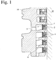
- Fig. 1 schematically shows a cross section of a stuffing box 10 comprising oil scraper rings 1 for a piston rod according to an embodiment of the present invention, three oil scraper rings 1 being stacked and received in each annular groove.
- Each oil scraper ring 1 comprises a rail 2 coming into sliding contact with an outer peripheral surface of a reciprocally movable piston rod 30 at an inner-side longitudinal center, and a groove 7 receiving an annular coil spring 3 for pressing the rail 2 to the outer peripheral surface of the piston rod 30 at an outer-side longitudinal center.
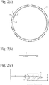
- Figs. 2(a) to 2(c) show an embodiment not in accordance with the present invention.
- Fig. 2(a) is a plan view showing a trisected ring body of the oil scraper ring 1 in a longitudinal direction
- Fig. 2(b) is a partial front view showing a radially outer peripheral surface of the ring
- Fig. 2(c) is a cross-sectional view taken along the line A-A in the ring.
- the oil scraper ring 1 comprises pluralities of oil drain grooves 4 only on an upper side surface, each oil drain groove 4 being inclined to have an increasing cross section area from the inner peripheral side to the outer peripheral side.
- the inclination angle ⁇ of the oil drain grooves 4 is preferably 3-30°, more preferably 5-20°, to a direction perpendicular to the axis of the ring body parallel to the reciprocal movement direction of the piston rod.
- the inner-side depth of the groove does not reach the rail 2.
- Figs. 3(a) to 3(c) show another embodiment of the present invention.
- Fig. 3(a) is a plan view showing a ring body of an oil scraper ring 11 in a longitudinal direction
- Fig. 3(b) is a partial front view showing a radially outer peripheral surface of the ring
- Fig. 3(c) is a cross-sectional view taken along the line B-B in the ring.
- the oil scraper ring 11 alternately comprises pluralities of oil drain grooves on both upper and lower sides, and the inner-side depth of the groove does not reach the rail 12.
- any of the inner-side distance (t) and outer-side distance (t') between an upper-side oil drain groove 14 and an adjacent lower-side oil drain groove 14 in a direction perpendicular to the axis of the ring body, namely, any of the inner-side and outer-side distances of a portion with no oil drain groove on upper and lower surfaces, is preferably 2 mm or more [see Fig. 3(a) ].
- the distances (t and t') are more preferably 2.5 mm or more, further preferably 3 mm or more.
- Figs. 4(a) to 4(c) show a further embodiment of the present invention, in which the oil drain grooves in the oil scraper ring shown in Figs. 3(a) to 3(c) are inclined.
- the inclination angle ⁇ of each oil drain groove 24 is preferably 3-10°, more preferably 5-8°, to a direction perpendicular to the axis of the ring body, by relation to the coil spring grooves 27.
- the area ratio of an inner-side opening of each oil drain groove 4, 14, 24 is preferably 5-35%, more preferably 7-30%, further preferably 9-27%.
- the oil scraper ring 11, 21 for a piston rod preferably has a pin 18, 28 on the upper surface of the ring body as shown in Figs. 5 and 6 , which are connected to another adjacent upper oil scraper ring 11, 21 for a piston rod, and a hole 19, 29 on the lower surface of the ring body as shown in Figs. 7 and 8 for receiving a pin 18, 28 of another adjacent lower oil scraper ring 11, 21 for a piston rod.
- Pluralities of these oil scraper rings 11, 21 for a piston rod are preferably stacked and received in one annular groove of the stuffing box 10, with the oil drain grooves 14, 24 of adjacent oil scraper rings 11, 21 for a piston rod opposing each other. In three stacked oil scraper rings in Figs.
- two lower oil scraper rings are arranged with their oil drain grooves 14, 24 opposing, resulting in the combined oil drain grooves having a doubled cross section area (14 + 14, 24 + 24), to make it easy to flow a cylinder oil or a system oil into the oil drain grooves.
- Figs. 11 and 12 show the cross sections of oil drain grooves adjacent to those shown in Figs. 9 and 10 , with two upper oil scraper rings having opposing oil drain grooves 14, 24.
- each oil scraper ring can have good followability to the piston rod 30.
- the oil scraper rings are inclined as the piston rod moves up and down, due to side clearance in the annular grooves. Though an oil scraper ring 110, 510, 610 having two rails as shown in Figs.
- circumferentially trisected oil scraper ring bodies of cast lead bronze each having an inner diameter of 270 mm, an outer diameter of 305 mm, a width (h1) of 7 mm, and a rail-including thickness (a1) of 17.5 mm, which comprised a rail having a width of 1.5 mm and a thickness of 4.5 mm, were produced for a large, low-speed, 6-cylinder, 2-cycle diesel engine having a bore diameter of 700 mm and stroke of 2600 mm.
- Each ring body was provided with five oil drain grooves each having a width of 22 mm, an inner-side depth of 2.0 mm and an inclination angle of 5° only on the upper surface, so that the entire ring had 15 grooves on the upper surface.
- a stuffing box comprised four grooves each receiving two stacked oil scraper rings. Because two stacked oil scraper rings were attached to each groove, a lower oil scraper ring was provided with a pin, and an upper oil scraper ring was provided with a pin-receiving hole, the pin being inserted into the pin-receiving hole. Coil springs of SWPB combined with these oil scraper rings were adjusted to provide a surface pressure of 0.13 MPa.
- CAC603 cast lead bronze
- stuffing boxes A each having the oil scraper rings of Example 1
- stuffing boxes B each having the oil scraper rings of Comparative Example 1 were provided respectively for six cylinders.
- the actual engine test was conducted by using the stuffing boxes B for all six cylinders for 1008 hours, and further 1008 hours with the stuffing boxes A changed to the stuffing boxes B.
- Table 1 shows the amount of drain (L/day) in each cylinder after 24 hours, 504 hours and 1008 hours, respectively, by a relative amount assuming that the amount of drain (L/day) after 24 hours was 1 in the first cylinder of Comparative Example 1.
- Table 1 Amount of Drain Comparative Example 1 Example 1 24 hours 504 hours 1008 hours 1032 hours 1512 hours 2016 hours First Cylinder 1 1.21 1.18 0.95 0.87 0.99 Second Cylinder 0.89 0.93 0.95 0.90 0.88 Third Cylinder 1.12 1.07 1.01 0.95 0.99 0.89 Fourth Cylinder 1.25 1.18 1.08 0.78 0.93 0.82 Fifth Cylinder 0.91 0.87 0.99 1.11 1.15 1.05 Sixth Cylinder 0.98 0.93 1.05 1.05 0.95 1.15 Total 6.15 6.19 6.26 5.74 5.84 5.78
- Example 1 The amount of initial drain (24 hours) in Example 1 was 93.3% of that in Comparative Example 1, indicating 6.7% reduction by using the oil scraper rings. Even when 1008 hours passed, the amount of drain was substantially unchanged.
- circumferentially trisected oil scraper ring bodies of cast lead bronze each having an inner diameter of 310 mm, an outer diameter of 345 mm, a width (h1) of 8 mm, and a rail-including thickness (a1) of 17.5 mm, which comprised a rail having a width of 1.5 mm and a thickness 4.5 mm, were produced for large, low-speed, 7-cylinder, 2-cycle diesel engine having a bore diameter of 800 mm and a stroke of 2800 mm.
- Each ring body was provided with five oil drain grooves on the upper surface and four oil drain grooves on the lower surface alternately, each groove having a width of 30 mm and a depth of 2.5 mm, so that the entire ring had 15 grooves on the upper surface and 12 grooves on the lower surface.
- the inner-side distance (t) was 5.37 mm
- the outer-side distance (t') was 7.64 mm.
- a stuffing box comprised four grooves each receiving two stacked oil scraper rings. Because two stacked oil scraper rings were attached to each groove, a lower oil scraper ring was provided with a pin, and an upper oil scraper ring was provided with a pin-receiving hole, the pin being inserted into the pin-receiving hole. With this connection, opposing oil drain grooves of vertically adjacent oil scraper rings were positioned. Coil springs of SWPB combined with these oil scraper rings were adjusted to provide a surface pressure of 0.24 MPa.
- circumferentially trisected conventional oil scraper ring bodies of cast iron each having a shape of an oil scraper ring 510 shown in Fig. 14(a) having an inner diameter of 310 mm, an outer diameter of 358 mm, a width (h1) of 22 mm, and a rail-including thickness (a1) of 26.5 mm, which comprised a rail having a width of 1.5 mm and a thickness of 4.5 mm, were produced.
- Coil springs of SWPB were adjusted to provide a conventional surface pressure of 0.38 MPa.
- stuffing boxes C each having the oil scraper rings of Example 2
- stuffing boxes D each having the oil scraper rings of Comparative Example 2 were provided respectively for seven cylinders.
- the actual engine test was conducted by using the stuffing boxes D for all seven cylinders for 1008 hours, and further 1008 hours with the stuffing boxes D changed to the stuffing boxes C.
- Table 2 shows the amount of drain (L/day) in each cylinder after 24 hours, 504 hours and 1008 hours, respectively, by a relative amount assuming that the amount of drain (L/day) after 24 hours was 1 in the first cylinder of Comparative Example 2.
- Table 2 Amount of Drain Comparative Example 2
- Example 2 24 hours 504 hours 1008 hours 1032 hours 1512 hours 2016 hours
- First Cylinder 1 1.51 1.35 0.22 0.25 0.26
- Seventh Cylinder 1.25 1.36 1.29 0.28 0.22 0.23 Total 7.12 7.97 8.13 1.49 1.58 1.56
- Example 2 The amount of initial drain (24 hours) in Example 2 was 20.9% of that in Comparative Example 2, indicating drastic reduction of 79.1% by using the oil scraper rings of the present invention. Even when 1008 hours passed, the amount of drain was substantially unchanged.
- circumferentially trisected oil scraper ring bodies of cast lead bronze each having an inner diameter of 138 mm, an outer diameter of 165 mm, a width (h1) of 6 mm, and a rail-free thickness (a1) of 9 mm, which comprised a rail having a width of 1.5 mm and a thickness of 4.5 mm, were produced for a large, low-speed, 3-cylinder, 2-cycle diesel engine having a bore diameter of 370 mm and a stroke of 880 mm.
- Each ring body was provided with five oil drain grooves on the upper surface and four oil drain grooves on the lower surface alternately, each groove having a width of 13 mm, an inner-side depth of 1.5 mm and an inclination angle of 8°, so that the entire ring had 15 grooves on the upper surface and 12 grooves on the lower surface.
- the inner-side distance (t) was 2.38 mm
- the outer-side distance (t') was 3.85 mm.
- a stuffing box comprised four grooves each receiving three stacked oil scraper rings. Because three stacked oil scraper rings were attached to each groove, a lower oil scraper ring was provided on the upper surface with a pin inserted into a pin-receiving hole of an intermediate oil scraper ring; an intermediate oil scraper ring was provided with a pin-receiving hole for receiving the pin of the lower oil scraper ring on the lower surface and a pin inserted into a pin-receiving hole of an upper oil scraper ring on the upper surface, and an upper oil scraper ring was provided on the lower surface with a pin-receiving hole for receiving the pin of the intermediate oil scraper ring. With this connection, opposing oil drain grooves of vertically adjacent oil scraper rings were positioned. Coil springs of SWPB combined with these oil scraper rings were adjusted to provide a surface pressure of 0.13 MPa.
- circumferentially trisected conventional oil scraper ring bodies of cast iron each having a shape of a two-rail oil scraper ring 110 shown in Fig. 13 having an inner diameter of 138 mm, an outer diameter of 169 mm, a width (h1) of 9 mm, and a rail-including thickness (a1) of 15.5 mm, which comprised a rail having a width of 1.5 mm and a thickness of 5.0 mm, were produced.
- Coil springs of SWPB were adjusted to provide a conventional surface pressure of 0.13 MPa.
- stuffing boxes E each having the oil scraper rings of Example 3
- stuffing boxes F each having the oil scraper rings of Comparative Example 3 were provided respectively for three cylinders.
- the actual engine test was conducted by using the stuffing boxes F for all three cylinders for 1008 hours, and further 1008 hours with the stuffing boxes F changed to the stuffing boxes E.
- Table 3 shows the amount of drain (L/day) in each cylinder after 24 hours, 504 hours and 1008 hours, respectively, by a relative amount assuming that the amount of drain (L/day) after 24 hours was 1 in the first cylinder of Comparative Example 3.
- Table 3 Amount of Drain Comparative Example 3
- Example 3 24 hours 504 hours 1008 hours 1032 hours 1512 hours 2016 hours
- First Cylinder 1 0.98 1.08 0.03 0.04 0.04
- Third Cylinder 0.93 1.05 1.11 0.01 0.02 0.04 Total 2.78 2.94 3.18 0.09 0.11 0.16
- Example 3 The amount of initial drain (24 hours) in Example 3 was 3% of that in Comparative Example 3, indicating remarkable reduction of 97% by using the oil scraper rings of the present invention. Even when 1008 hours passed, the amount of drain was substantially unchanged.
Landscapes
- Engineering & Computer Science (AREA)
- General Engineering & Computer Science (AREA)
- Mechanical Engineering (AREA)
- Chemical & Material Sciences (AREA)
- Combustion & Propulsion (AREA)
- Pistons, Piston Rings, And Cylinders (AREA)
- Sealing Devices (AREA)
Claims (9)
- Ölabstreifring (11, 21) für eine Kolbenstange (30), umfassend:einen Ringkörper mit einer Schiene (12, 22), die mit einer äußeren peripheren Oberfläche einer gegenseitig bewegbaren Kolbenstange (30) in Gleitkontakt kommt; undeine ringförmige Spiralfeder (3) zum Pressen der Schiene (12, 22) an die äußere periphere Oberfläche der Kolbenstange (30);wobei der Ringkörper umlaufend in mindestens zwei unterteilt ist;wobei der Ringkörper die Schiene (12, 22) an einer innenseitigen Längsmittellinie und eine Rille (17, 27), die die Spiralfeder (3) aufnimmt, an einer außenseitigen Längsmittellinie umfasst;dadurch gekennzeichnet, dass der Ringkörper ferner Vielzahlen von Ölablaufrillen (14, 24) vertikal abwechselnd auf sowohl oberen als auch unteren Oberflächen umfasst.
- Ölabstreifring (11, 21) für eine Kolbenstange (30) gemäß Anspruch 1, wobei die Ölablaufrillen (14, 24) geneigt sind, so dass sie sich von der Innenseite zur Außenseite hin aufweiten.
- Ölabstreifring (11, 21) für eine Kolbenstange (30) gemäß Anspruch 1, wobei der Neigungswinkel von jeder Ölablaufrille (14, 24) 3 - 10° zu einer Richtung senkrecht zur Achse des Ringkörpers beträgt.
- Ölabstreifring (11, 21) für eine Kolbenstange (30) gemäß einem der Ansprüche 1 bis 3, wobei sowohl der Innenseite-Abstand (t) als auch der Außenseite-Abstand (t') zwischen einer obere Seite-Ölablaufrille und einer benachbarten untere Seite-Ölablaufrille in einer Richtung senkrecht zur Achse des Ringkörpers 2 mm oder mehr betragen.
- Ölabstreifring (11, 21) für eine Kolbenstange (30) gemäß einem der Ansprüche 1 bis 4, wobei das Flächenverhältnis einer innenseitigen Öffnung von jeder Ölablaufrille 5 - 35 % beträgt.
- Ölabstreifring (11, 21) für eine Kolbenstange (30) gemäß einem der Ansprüche 1 bis 5, wobei der Ringkörper einen Stift (18, 28) auf der oberen Oberfläche, die mit einem benachbarten oberen Ölabstreifring (11, 21) verbunden ist, aufweist.
- Ölabstreifring (11, 21) für eine Kolbenstange (30) gemäß einem der Ansprüche 1 bis 6, wobei der Ringkörper ein Stift-aufnehmendes Loch (19, 29) auf der unteren Oberfläche, die mit einem benachbarten unteren Ölabstreifring verbunden ist, aufweist.
- Stopfbuchse, umfassend Vielzahlen von Ölabstreifringen (11, 21) gemäß Anspruch 6 oder 7, die in ihrer ringförmigen Rille aufgenommen werden.
- Stopfbuchse gemäß Anspruch 8, umfassend eine Kombination von Ölabstreifringen (11, 21) für eine Kolbenstange (30), wobei sich die Ölablaufrillen (14, 24) von benachbarten Ölabstreifringen gegenüberliegen.
Applications Claiming Priority (3)
| Application Number | Priority Date | Filing Date | Title |
|---|---|---|---|
| JP2014090008A JP6313107B2 (ja) | 2014-04-24 | 2014-04-24 | ピストンロッド用オイル掻きリング及び当該オイル掻きリングを備えたスタフィングボックス |
| JP2014090034A JP6313645B2 (ja) | 2014-04-24 | 2014-04-24 | ピストンロッド用オイル掻きリング及び当該オイル掻きリングを備えたスタフィングボックス |
| PCT/JP2015/062354 WO2015163399A1 (ja) | 2014-04-24 | 2015-04-23 | ピストンロッド用オイル掻きリング及び当該オイル掻きリングを備えたスタフィングボックス |
Publications (3)
| Publication Number | Publication Date |
|---|---|
| EP3135963A1 EP3135963A1 (de) | 2017-03-01 |
| EP3135963A4 EP3135963A4 (de) | 2018-02-14 |
| EP3135963B1 true EP3135963B1 (de) | 2020-01-29 |
Family
ID=54332561
Family Applications (1)
| Application Number | Title | Priority Date | Filing Date |
|---|---|---|---|
| EP15783127.2A Active EP3135963B1 (de) | 2014-04-24 | 2015-04-23 | Ölabstreifring für kolbenstange und mit besagtem ölabstreifring ausgestattete stopfbuchse |
Country Status (5)
| Country | Link |
|---|---|
| EP (1) | EP3135963B1 (de) |
| KR (1) | KR102350324B1 (de) |
| CN (1) | CN106233050B (de) |
| DK (1) | DK3135963T3 (de) |
| WO (1) | WO2015163399A1 (de) |
Families Citing this family (1)
| Publication number | Priority date | Publication date | Assignee | Title |
|---|---|---|---|---|
| JP6675157B2 (ja) * | 2015-06-05 | 2020-04-01 | 株式会社リケン | オイルコントロールリング |
Family Cites Families (8)
| Publication number | Priority date | Publication date | Assignee | Title |
|---|---|---|---|---|
| JPS5884349U (ja) * | 1981-12-03 | 1983-06-08 | 日立造船株式会社 | ディ−ゼル機関の軸封装置 |
| CH660407A5 (de) * | 1983-08-25 | 1987-04-15 | Alfred F Schirmer | Dichtring fuer kolbenstangen. |
| CN1316187C (zh) * | 2001-11-22 | 2007-05-16 | 米勒及布劳赫里有限公司 | 分段刮油环 |
| US6959930B2 (en) * | 2003-05-15 | 2005-11-01 | Delaware Capital Formation, Inc. | Combination oil scrapper ring/gas seal assembly |
| JP2006144700A (ja) * | 2004-11-22 | 2006-06-08 | Toyota Motor Corp | 内燃機関用エンジンのピストン及び内燃機関用エンジンのピストンとピストンリングの組合せ |
| JP2008133923A (ja) * | 2006-11-29 | 2008-06-12 | Teikoku Piston Ring Co Ltd | 組合せオイルリング |
| JP5173236B2 (ja) * | 2007-04-10 | 2013-04-03 | 株式会社リケン | スタフィングボックス |
| JP5371582B2 (ja) * | 2009-07-02 | 2013-12-18 | 株式会社リケン | ピストンロッド用オイル掻きリング及びその製造方法、並びに当該オイル掻きリングを備えたスタフィングボックス |
-
2015
- 2015-04-23 EP EP15783127.2A patent/EP3135963B1/de active Active
- 2015-04-23 CN CN201580021331.6A patent/CN106233050B/zh active Active
- 2015-04-23 DK DK15783127.2T patent/DK3135963T3/da active
- 2015-04-23 WO PCT/JP2015/062354 patent/WO2015163399A1/ja not_active Ceased
- 2015-04-23 KR KR1020167032822A patent/KR102350324B1/ko active Active
Non-Patent Citations (1)
| Title |
|---|
| None * |
Also Published As
| Publication number | Publication date |
|---|---|
| KR102350324B1 (ko) | 2022-01-14 |
| WO2015163399A1 (ja) | 2015-10-29 |
| KR20160146953A (ko) | 2016-12-21 |
| CN106233050B (zh) | 2018-11-30 |
| CN106233050A (zh) | 2016-12-14 |
| EP3135963A1 (de) | 2017-03-01 |
| EP3135963A4 (de) | 2018-02-14 |
| DK3135963T3 (da) | 2020-04-20 |
Similar Documents
| Publication | Publication Date | Title |
|---|---|---|
| US20140311437A1 (en) | Piston ring for a piston of an internal combustion engine, and a method for producing same | |
| US20100319661A1 (en) | Cylinder-Mounted oil wiper for an opposed piston engine | |
| US10337615B2 (en) | Machine with reduced cylinder friction | |
| US8256389B2 (en) | Cylinder block | |
| EP3135963B1 (de) | Ölabstreifring für kolbenstange und mit besagtem ölabstreifring ausgestattete stopfbuchse | |
| US10495225B2 (en) | Compression piston ring with profiled section | |
| JP6314015B2 (ja) | ピストンとピストンリングの組合せ | |
| US20170009885A1 (en) | Piston ring configured to reduce friction | |
| US10837554B2 (en) | Piston compression rings of copper-nickel-tin alloys | |
| JP6313645B2 (ja) | ピストンロッド用オイル掻きリング及び当該オイル掻きリングを備えたスタフィングボックス | |
| JP2023050681A (ja) | ピストンリングの組合せ、及び内燃機関 | |
| RU2005121918A (ru) | Поршневой двигатель | |
| DE10340301A1 (de) | Mehrteiliger Ölabstreifring für Kolben von Verbrennungsmotoren | |
| JP6313107B2 (ja) | ピストンロッド用オイル掻きリング及び当該オイル掻きリングを備えたスタフィングボックス | |
| US2030927A (en) | Piston packing ring | |
| JP6010278B2 (ja) | ディーゼルエンジン用ピストンリングの組合せ | |
| JP6675157B2 (ja) | オイルコントロールリング | |
| FI20175977A7 (fi) | Polttovoimakoneen sylinteri | |
| EP3724479B1 (de) | Antipolierring | |
| DK154905B (da) | Stempelring til en stempelforbraendingsmotor med smoereaabninger i cylindervaeggen | |
| CN212775517U (zh) | 一种油缸活塞主密封结构 | |
| JPS6023487Y2 (ja) | エンジンのピストン | |
| CN204591512U (zh) | 耐磨耐高温活塞 | |
| CN203035370U (zh) | 柴油机及活塞 | |
| RU2312263C2 (ru) | Поршневое уплотнение |
Legal Events
| Date | Code | Title | Description |
|---|---|---|---|
| STAA | Information on the status of an ep patent application or granted ep patent |
Free format text: STATUS: THE INTERNATIONAL PUBLICATION HAS BEEN MADE |
|
| PUAI | Public reference made under article 153(3) epc to a published international application that has entered the european phase |
Free format text: ORIGINAL CODE: 0009012 |
|
| STAA | Information on the status of an ep patent application or granted ep patent |
Free format text: STATUS: REQUEST FOR EXAMINATION WAS MADE |
|
| 17P | Request for examination filed |
Effective date: 20161121 |
|
| AK | Designated contracting states |
Kind code of ref document: A1 Designated state(s): AL AT BE BG CH CY CZ DE DK EE ES FI FR GB GR HR HU IE IS IT LI LT LU LV MC MK MT NL NO PL PT RO RS SE SI SK SM TR |
|
| AX | Request for extension of the european patent |
Extension state: BA ME |
|
| DAV | Request for validation of the european patent (deleted) | ||
| DAX | Request for extension of the european patent (deleted) | ||
| A4 | Supplementary search report drawn up and despatched |
Effective date: 20180117 |
|
| RIC1 | Information provided on ipc code assigned before grant |
Ipc: F16J 15/18 20060101AFI20180111BHEP Ipc: F16J 15/26 20060101ALI20180111BHEP Ipc: F02F 11/00 20060101ALI20180111BHEP |
|
| GRAP | Despatch of communication of intention to grant a patent |
Free format text: ORIGINAL CODE: EPIDOSNIGR1 |
|
| STAA | Information on the status of an ep patent application or granted ep patent |
Free format text: STATUS: GRANT OF PATENT IS INTENDED |
|
| INTG | Intention to grant announced |
Effective date: 20190823 |
|
| GRAS | Grant fee paid |
Free format text: ORIGINAL CODE: EPIDOSNIGR3 |
|
| GRAA | (expected) grant |
Free format text: ORIGINAL CODE: 0009210 |
|
| STAA | Information on the status of an ep patent application or granted ep patent |
Free format text: STATUS: THE PATENT HAS BEEN GRANTED |
|
| AK | Designated contracting states |
Kind code of ref document: B1 Designated state(s): AL AT BE BG CH CY CZ DE DK EE ES FI FR GB GR HR HU IE IS IT LI LT LU LV MC MK MT NL NO PL PT RO RS SE SI SK SM TR |
|
| REG | Reference to a national code |
Ref country code: GB Ref legal event code: FG4D |
|
| REG | Reference to a national code |
Ref country code: CH Ref legal event code: EP |
|
| REG | Reference to a national code |
Ref country code: AT Ref legal event code: REF Ref document number: 1228725 Country of ref document: AT Kind code of ref document: T Effective date: 20200215 |
|
| REG | Reference to a national code |
Ref country code: IE Ref legal event code: FG4D |
|
| REG | Reference to a national code |
Ref country code: DE Ref legal event code: R096 Ref document number: 602015046092 Country of ref document: DE |
|
| REG | Reference to a national code |
Ref country code: CH Ref legal event code: NV Representative=s name: RIEDERER HASLER AND PARTNER PATENTANWAELTE AG, LI |
|
| REG | Reference to a national code |
Ref country code: DK Ref legal event code: T3 Effective date: 20200417 |
|
| REG | Reference to a national code |
Ref country code: NL Ref legal event code: MP Effective date: 20200129 |
|
| PG25 | Lapsed in a contracting state [announced via postgrant information from national office to epo] |
Ref country code: FI Free format text: LAPSE BECAUSE OF FAILURE TO SUBMIT A TRANSLATION OF THE DESCRIPTION OR TO PAY THE FEE WITHIN THE PRESCRIBED TIME-LIMIT Effective date: 20200129 Ref country code: RS Free format text: LAPSE BECAUSE OF FAILURE TO SUBMIT A TRANSLATION OF THE DESCRIPTION OR TO PAY THE FEE WITHIN THE PRESCRIBED TIME-LIMIT Effective date: 20200129 Ref country code: NO Free format text: LAPSE BECAUSE OF FAILURE TO SUBMIT A TRANSLATION OF THE DESCRIPTION OR TO PAY THE FEE WITHIN THE PRESCRIBED TIME-LIMIT Effective date: 20200429 Ref country code: PT Free format text: LAPSE BECAUSE OF FAILURE TO SUBMIT A TRANSLATION OF THE DESCRIPTION OR TO PAY THE FEE WITHIN THE PRESCRIBED TIME-LIMIT Effective date: 20200621 |
|
| REG | Reference to a national code |
Ref country code: LT Ref legal event code: MG4D |
|
| PG25 | Lapsed in a contracting state [announced via postgrant information from national office to epo] |
Ref country code: SE Free format text: LAPSE BECAUSE OF FAILURE TO SUBMIT A TRANSLATION OF THE DESCRIPTION OR TO PAY THE FEE WITHIN THE PRESCRIBED TIME-LIMIT Effective date: 20200129 Ref country code: LV Free format text: LAPSE BECAUSE OF FAILURE TO SUBMIT A TRANSLATION OF THE DESCRIPTION OR TO PAY THE FEE WITHIN THE PRESCRIBED TIME-LIMIT Effective date: 20200129 Ref country code: GR Free format text: LAPSE BECAUSE OF FAILURE TO SUBMIT A TRANSLATION OF THE DESCRIPTION OR TO PAY THE FEE WITHIN THE PRESCRIBED TIME-LIMIT Effective date: 20200430 Ref country code: BG Free format text: LAPSE BECAUSE OF FAILURE TO SUBMIT A TRANSLATION OF THE DESCRIPTION OR TO PAY THE FEE WITHIN THE PRESCRIBED TIME-LIMIT Effective date: 20200429 Ref country code: IS Free format text: LAPSE BECAUSE OF FAILURE TO SUBMIT A TRANSLATION OF THE DESCRIPTION OR TO PAY THE FEE WITHIN THE PRESCRIBED TIME-LIMIT Effective date: 20200529 Ref country code: HR Free format text: LAPSE BECAUSE OF FAILURE TO SUBMIT A TRANSLATION OF THE DESCRIPTION OR TO PAY THE FEE WITHIN THE PRESCRIBED TIME-LIMIT Effective date: 20200129 |
|
| PG25 | Lapsed in a contracting state [announced via postgrant information from national office to epo] |
Ref country code: NL Free format text: LAPSE BECAUSE OF FAILURE TO SUBMIT A TRANSLATION OF THE DESCRIPTION OR TO PAY THE FEE WITHIN THE PRESCRIBED TIME-LIMIT Effective date: 20200129 |
|
| PG25 | Lapsed in a contracting state [announced via postgrant information from national office to epo] |
Ref country code: EE Free format text: LAPSE BECAUSE OF FAILURE TO SUBMIT A TRANSLATION OF THE DESCRIPTION OR TO PAY THE FEE WITHIN THE PRESCRIBED TIME-LIMIT Effective date: 20200129 Ref country code: SM Free format text: LAPSE BECAUSE OF FAILURE TO SUBMIT A TRANSLATION OF THE DESCRIPTION OR TO PAY THE FEE WITHIN THE PRESCRIBED TIME-LIMIT Effective date: 20200129 Ref country code: SK Free format text: LAPSE BECAUSE OF FAILURE TO SUBMIT A TRANSLATION OF THE DESCRIPTION OR TO PAY THE FEE WITHIN THE PRESCRIBED TIME-LIMIT Effective date: 20200129 Ref country code: ES Free format text: LAPSE BECAUSE OF FAILURE TO SUBMIT A TRANSLATION OF THE DESCRIPTION OR TO PAY THE FEE WITHIN THE PRESCRIBED TIME-LIMIT Effective date: 20200129 Ref country code: CZ Free format text: LAPSE BECAUSE OF FAILURE TO SUBMIT A TRANSLATION OF THE DESCRIPTION OR TO PAY THE FEE WITHIN THE PRESCRIBED TIME-LIMIT Effective date: 20200129 Ref country code: LT Free format text: LAPSE BECAUSE OF FAILURE TO SUBMIT A TRANSLATION OF THE DESCRIPTION OR TO PAY THE FEE WITHIN THE PRESCRIBED TIME-LIMIT Effective date: 20200129 Ref country code: RO Free format text: LAPSE BECAUSE OF FAILURE TO SUBMIT A TRANSLATION OF THE DESCRIPTION OR TO PAY THE FEE WITHIN THE PRESCRIBED TIME-LIMIT Effective date: 20200129 |
|
| REG | Reference to a national code |
Ref country code: DE Ref legal event code: R097 Ref document number: 602015046092 Country of ref document: DE |
|
| REG | Reference to a national code |
Ref country code: DE Ref legal event code: R119 Ref document number: 602015046092 Country of ref document: DE |
|
| REG | Reference to a national code |
Ref country code: AT Ref legal event code: MK05 Ref document number: 1228725 Country of ref document: AT Kind code of ref document: T Effective date: 20200129 |
|
| PG25 | Lapsed in a contracting state [announced via postgrant information from national office to epo] |
Ref country code: MC Free format text: LAPSE BECAUSE OF FAILURE TO SUBMIT A TRANSLATION OF THE DESCRIPTION OR TO PAY THE FEE WITHIN THE PRESCRIBED TIME-LIMIT Effective date: 20200129 |
|
| PLBE | No opposition filed within time limit |
Free format text: ORIGINAL CODE: 0009261 |
|
| STAA | Information on the status of an ep patent application or granted ep patent |
Free format text: STATUS: NO OPPOSITION FILED WITHIN TIME LIMIT |
|
| 26N | No opposition filed |
Effective date: 20201030 |
|
| PG25 | Lapsed in a contracting state [announced via postgrant information from national office to epo] |
Ref country code: DE Free format text: LAPSE BECAUSE OF NON-PAYMENT OF DUE FEES Effective date: 20201103 Ref country code: AT Free format text: LAPSE BECAUSE OF FAILURE TO SUBMIT A TRANSLATION OF THE DESCRIPTION OR TO PAY THE FEE WITHIN THE PRESCRIBED TIME-LIMIT Effective date: 20200129 Ref country code: LU Free format text: LAPSE BECAUSE OF NON-PAYMENT OF DUE FEES Effective date: 20200423 Ref country code: FR Free format text: LAPSE BECAUSE OF NON-PAYMENT OF DUE FEES Effective date: 20200430 Ref country code: IT Free format text: LAPSE BECAUSE OF FAILURE TO SUBMIT A TRANSLATION OF THE DESCRIPTION OR TO PAY THE FEE WITHIN THE PRESCRIBED TIME-LIMIT Effective date: 20200129 |
|
| REG | Reference to a national code |
Ref country code: BE Ref legal event code: MM Effective date: 20200430 |
|
| PG25 | Lapsed in a contracting state [announced via postgrant information from national office to epo] |
Ref country code: SI Free format text: LAPSE BECAUSE OF FAILURE TO SUBMIT A TRANSLATION OF THE DESCRIPTION OR TO PAY THE FEE WITHIN THE PRESCRIBED TIME-LIMIT Effective date: 20200129 Ref country code: PL Free format text: LAPSE BECAUSE OF FAILURE TO SUBMIT A TRANSLATION OF THE DESCRIPTION OR TO PAY THE FEE WITHIN THE PRESCRIBED TIME-LIMIT Effective date: 20200129 Ref country code: BE Free format text: LAPSE BECAUSE OF NON-PAYMENT OF DUE FEES Effective date: 20200430 |
|
| GBPC | Gb: european patent ceased through non-payment of renewal fee |
Effective date: 20200429 |
|
| PG25 | Lapsed in a contracting state [announced via postgrant information from national office to epo] |
Ref country code: GB Free format text: LAPSE BECAUSE OF NON-PAYMENT OF DUE FEES Effective date: 20200429 Ref country code: IE Free format text: LAPSE BECAUSE OF NON-PAYMENT OF DUE FEES Effective date: 20200423 |
|
| PG25 | Lapsed in a contracting state [announced via postgrant information from national office to epo] |
Ref country code: TR Free format text: LAPSE BECAUSE OF FAILURE TO SUBMIT A TRANSLATION OF THE DESCRIPTION OR TO PAY THE FEE WITHIN THE PRESCRIBED TIME-LIMIT Effective date: 20200129 Ref country code: MT Free format text: LAPSE BECAUSE OF FAILURE TO SUBMIT A TRANSLATION OF THE DESCRIPTION OR TO PAY THE FEE WITHIN THE PRESCRIBED TIME-LIMIT Effective date: 20200129 Ref country code: CY Free format text: LAPSE BECAUSE OF FAILURE TO SUBMIT A TRANSLATION OF THE DESCRIPTION OR TO PAY THE FEE WITHIN THE PRESCRIBED TIME-LIMIT Effective date: 20200129 |
|
| PG25 | Lapsed in a contracting state [announced via postgrant information from national office to epo] |
Ref country code: MK Free format text: LAPSE BECAUSE OF FAILURE TO SUBMIT A TRANSLATION OF THE DESCRIPTION OR TO PAY THE FEE WITHIN THE PRESCRIBED TIME-LIMIT Effective date: 20200129 Ref country code: AL Free format text: LAPSE BECAUSE OF FAILURE TO SUBMIT A TRANSLATION OF THE DESCRIPTION OR TO PAY THE FEE WITHIN THE PRESCRIBED TIME-LIMIT Effective date: 20200129 |
|
| P01 | Opt-out of the competence of the unified patent court (upc) registered |
Effective date: 20230517 |
|
| PGFP | Annual fee paid to national office [announced via postgrant information from national office to epo] |
Ref country code: DK Payment date: 20250411 Year of fee payment: 11 |
|
| PGFP | Annual fee paid to national office [announced via postgrant information from national office to epo] |
Ref country code: CH Payment date: 20250501 Year of fee payment: 11 |