EP3136041B1 - Appareil et procédé d'assemblage et de libération de vêtement - Google Patents
Appareil et procédé d'assemblage et de libération de vêtement Download PDFInfo
- Publication number
- EP3136041B1 EP3136041B1 EP16192729.8A EP16192729A EP3136041B1 EP 3136041 B1 EP3136041 B1 EP 3136041B1 EP 16192729 A EP16192729 A EP 16192729A EP 3136041 B1 EP3136041 B1 EP 3136041B1
- Authority
- EP
- European Patent Office
- Prior art keywords
- pin
- slot
- shaped clip
- channel
- clip
- Prior art date
- Legal status (The legal status is an assumption and is not a legal conclusion. Google has not performed a legal analysis and makes no representation as to the accuracy of the status listed.)
- Active
Links
Images

Classifications
-
- A—HUMAN NECESSITIES
- A47—FURNITURE; DOMESTIC ARTICLES OR APPLIANCES; COFFEE MILLS; SPICE MILLS; SUCTION CLEANERS IN GENERAL
- A47G—HOUSEHOLD OR TABLE EQUIPMENT
- A47G25/00—Household implements used in connection with wearing apparel; Dress, hat or umbrella holders
- A47G25/90—Devices for domestic use for assisting in putting-on or pulling-off clothing, e.g. stockings or trousers
-
- A—HUMAN NECESSITIES
- A41—WEARING APPAREL
- A41F—GARMENT FASTENINGS; SUSPENDERS
- A41F1/00—Fastening devices specially adapted for garments
-
- A—HUMAN NECESSITIES
- A44—HABERDASHERY; JEWELLERY
- A44B—BUTTONS, PINS, BUCKLES, SLIDE FASTENERS, OR THE LIKE
- A44B11/00—Buckles; Similar fasteners for interconnecting straps or the like, e.g. for safety belts
- A44B11/25—Buckles; Similar fasteners for interconnecting straps or the like, e.g. for safety belts with two or more separable parts
- A44B11/2592—Buckles; Similar fasteners for interconnecting straps or the like, e.g. for safety belts with two or more separable parts fastening by sliding in the main plane or a plane parallel to the main plane of the buckle
- A44B11/2596—Buckles; Similar fasteners for interconnecting straps or the like, e.g. for safety belts with two or more separable parts fastening by sliding in the main plane or a plane parallel to the main plane of the buckle the movement being transverse to the longitudinal direction of the strap or chain
-
- F—MECHANICAL ENGINEERING; LIGHTING; HEATING; WEAPONS; BLASTING
- F41—WEAPONS
- F41H—ARMOUR; ARMOURED TURRETS; ARMOURED OR ARMED VEHICLES; MEANS OF ATTACK OR DEFENCE, e.g. CAMOUFLAGE, IN GENERAL
- F41H1/00—Personal protection gear
- F41H1/02—Armoured or projectile- or missile-resistant garments; Composite protection fabrics
-
- A—HUMAN NECESSITIES
- A41—WEARING APPAREL
- A41D—OUTERWEAR; PROTECTIVE GARMENTS; ACCESSORIES
- A41D2300/00—Details of garments
- A41D2300/30—Closures
-
- A—HUMAN NECESSITIES
- A41—WEARING APPAREL
- A41D—OUTERWEAR; PROTECTIVE GARMENTS; ACCESSORIES
- A41D2300/00—Details of garments
- A41D2300/50—Seams
-
- A—HUMAN NECESSITIES
- A41—WEARING APPAREL
- A41D—OUTERWEAR; PROTECTIVE GARMENTS; ACCESSORIES
- A41D2400/00—Functions or special features of garments
- A41D2400/44—Donning facilities
-
- Y—GENERAL TAGGING OF NEW TECHNOLOGICAL DEVELOPMENTS; GENERAL TAGGING OF CROSS-SECTIONAL TECHNOLOGIES SPANNING OVER SEVERAL SECTIONS OF THE IPC; TECHNICAL SUBJECTS COVERED BY FORMER USPC CROSS-REFERENCE ART COLLECTIONS [XRACs] AND DIGESTS
- Y10—TECHNICAL SUBJECTS COVERED BY FORMER USPC
- Y10T—TECHNICAL SUBJECTS COVERED BY FORMER US CLASSIFICATION
- Y10T24/00—Buckles, buttons, clasps, etc.
- Y10T24/34—Combined diverse multipart fasteners
- Y10T24/3427—Clasp
- Y10T24/346—Clasp and pin
Definitions
- the present invention relates generally to assembly and release apparatus and method for a garment such as a ballistic vest or the like, and more particularly, which provides a quiet and rapid manner of donning and doffing the garment, so as to be usable for both standard doffing and donning, and rapid release for emergency and injury situations and the like.
- the ballistic vest disclosed in U.S. Pat. No. 7,047,570 which discloses front and rear portions that can separate completely from one another, while a waist belt and cummerbund of the vest have an end that separates from at least one of the front and rear portions.
- This vest uses a complex system of belting and straps for normal donning and doffing. Because of this complexity, a rapid release system is provided which utilizes a flexible retainer including a cable that can be quickly pulled to break the vest into pieces for removal.
- a disadvantage of this system is that once it is used, reassembly of the vest and rigging of the rapid release system is time consuming and involves threading portions of the retainer through regions of the vest, which can be difficult, particularly under challenging condition such as darkness and combat, and during which assembly the user is left unprotected.
- the vest is heavier than desired.
- EP 2 363 034 A1 and US 2010/0263171 A1 describe both a coupling device including a plug member having a rectangular rail support part and a rectangular rail connected to an outer end of the rectangular rail support part, and a socket member having a rectangular rail groove into which the rectangular rail is fitted and a slot which is defined through a side wall of the socket member defining the rail groove to extend in a lengthwise direction of the rail groove so as to allow the rail support part to pass therethrough.
- the apparatus includes a C-shaped clip defining a channel and an open slot extending along the channel, open at at least one end of the clip, and including at least one element configured for attaching the C-shaped clip to a first location on the garment.
- the apparatus includes a pin slidably receivable in the channel of the C-shaped clip through the open end to assemble the C-shaped clip and the pin together.
- the pin has a tab or strip configured to extend through the slot, for attaching the pin to a second location on the garment, the slot being sufficiently small to prevent passage of the pin therethrough.
- the apparatus additionally includes at least one detent element associated with the C-shaped clip, cooperatively engageable with the pin for retaining the pin in the channel, the detent element being releasable in a predetermined manner to allow slidably removing the pin from the channel through the open end.
- the pin can be slidably inserted into the channel of the C-shaped clip, and the detent element or elements engaged, to securely hold the locations of the garment together. Separating the locations entails simply releasing the detent element or elements.
- a preferred garment is a ballistic vest, and the locations can comprise, for instance, but are not limited to, and edge or edges of a front panel of the vest, and side elements such as a belt or cummerbund, and also an upper edge of the front panel and a shoulder strap or straps.
- the pin can be engaged with and disengaged from the clip quickly and easily so that the garment can be donned and doffed rapidly, which is a valuable advantage under the conditions set forth above.
- the at least one detent element comprises a tab extending from the C-shape clip, cooperatively engageable with or receivable in a notch in the pin, and removable therefrom in a manual pulling motion, which can be accomplished under stressful and low visibility conditions.
- the C-shaped clip and the pin is elongate, and the tab located at about a central portion of the C-shaped clip. Additionally the assembled clip and pin can be generally flat, so as to not be obtrusive.
- the detent element can comprise a cover, e.g., of a fabric material, over the open end or ends of the C-shaped clip, and which can be easily grasped and moved using a finger or fingers, so as to also be quickly and simply accomplished.
- the clip and/or the pin can be fabric covered, e.g., with a camouflage fabric if desired.
- the channel of the C-shaped clip and the pin have mating D-shapes when viewed from the end thereof, with flat surfaces of the D-shape being located adjacent to opposite sides of the slot, for added strength, and to improve tactile feel for assembly under low light and other difficult conditions.
- the C-shaped clip and the pin have mating surfaces bounding the channel adjacent to at least one side of the slot, which are tapered at less than a 90 degree angle, e.g., 75-85 degrees, to the slot such that when the pin is located in the channel and a force is exerted against the tab or strip in a direction to pull the pin toward or through the slot, the surface of the clip adjacent to the slot will be drawn toward the slot to prevent passage of the pin therethrough.
- This feature can be incorporated with the D-shaped feature discussed above, and can be located on opposite sides of the slot, for greater strength.
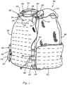
- assembly and release apparatus 20 constructed and operable according to the teachings of the present invention, are shown at several location on a representative garment, which here is a ballistic vest 36., that provides a quiet and rapid manner of operation, usable for both standard donning and doffing, as well as rapid release, and which provides at least some weight advantage, and overcomes one or more of the disadvantages set forth above.
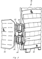
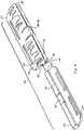
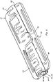
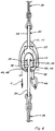
- the assembly and release apparatus 20 includes a C-shape female clip 22 which is attached to a first element or location of the garment to be connected to another element or location, and an elongate male pin 24 attached to the second element or section and with relative longitudinal movement as denoted by arrow LM in FIG. 4 , is cooperatively receivable in the C-shape clip 22 for connecting the garment element or sections together.
- the C shape clip 22 extends partially circumferentially about and defines an elongate channel 26 open at at least one longitudinal end 28, 30 for receiving the elongate pin 24, and has a longitudinally extending slot 32 along the channel 26 also.
- Both the C-shape clip 22 and the pin 24 are preferably attached to its respective element or location of the garment (vest 36) by at least one tab or strip 34 that extends longitudinally along the clip 22 or pin 24, and the tab or strip 34 of the pin 24 is cooperatively received in the slot 32 of the clip 22.
- the pin 24 preferably has a sectional extent X1 transverse to the longitudinal direction that about equal to or only marginally smaller than the transverse extent Y1 of the channel, so that the pin 24 is relatively easily slidable along the channel 26 by movement LM, but not loose.
- the slot 32 is just sufficient in width Y2 to receive the tab or strip 34, which is relatively narrow in thickness (X2) transverse to the longitudinal direction, but not large enough for passage of the pin 24 transversely from the channel 26.
- the channel 26 and pin 24 can have substantially mating cross sectional shapes, such as, but not limited to, a round shape, or a D-shape, as desired or required for a particular application.
- the C-shape clip 22 is preferably sufficiently strong and rigid so as to resist breaking or deforming under forces anticipated to be exerted thereagainst, so as to be capable of restraining the pin 24 from transverse removal therefrom through the slot 32 under transverse and other forces anticipated to be exerted during use of the garment, as denoted by arrow F in FIG. 6 .
- Suitable materials for both clip 22 and pin 24 can include metals and strong plastics such as a nylon or fiber reinforced resin. Such forces can vary and may be specifically designated in a performance specification for the particular garment, e.g., a ballistic vest 36 or other garment for military or law enforcement use.
- Release apparatus 20 additionally includes at least one detent element 38 configured and operable for retaining pin 24 in the longitudinal direction in channel 26 under forces anticipated to be exerted thereagainst during use of the garment, but which detent element is movable or deformable in a predetermined manner, e.g., by manual manipulation, to allow removal of the pin 24.
- the detent element can comprise a transversely extending tab 40 on clip 22, cooperatively receivable in a notch 42 in pin 24, both of which can be located along the respective lengths thereof, here, at a center or middle location along the lengths of the clip and pin.
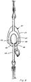
- a convenient graspable feature such as a fabric loop or cord 44 or the like, can be provided in connection with tab 40 to facilitate manually grasping tab 40 and pulling it transversely away from notch 42 when it is desired to release the pin, as denoted by arrow R in FIG. 7 .
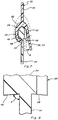
- C-shaped clip 22 and pin 24 preferably have mating surfaces 46, 48 bounding the channel adjacent to at least one side of the slot (here on both sides), which are tapered at less than a 90 degree angle A ( FIG. 8 ), e.g., 75-85 degrees, to strip 34 (and slot 32) such that when pin 24 is located in channel 26 and a force F ( FIG. 6 ) is exerted against tab or strip 34 in a direction to pull pin 24 toward or through slot 32, surfaces 48 of pin 24 will push against and draw surfaces 46 of the clip toward the slot to prevent passage of the pin therethrough for additional strength.
- a 90 degree angle A FIG. 8
- surfaces 46 and 48 can be about perpendicular to slot 32 and strip 34, if desired.
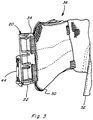
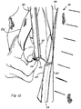
- the assembly and release apparatus of the invention can be incorporated at various locations on a garment, such as, but not limited to, for connecting a belt or cummerbund 50 to a side edge of a front panel 52 of a ballistic vest 36, as shown in various of the FIGS.
- Another location is for connecting the upper edge of front panel 52 to shoulder straps 54, as also shown.
- Still other locations can include cummerbund or belt to a side edge of a rear panel 56 of the vest, and/or shoulder strap to rear panel, to name a few options.
- apparatus 20 can be sized accordingly for a particular location, to provide the required strength.
- the clip 22 and pin 24 can be attached to the side of the connection that is most advantageous, as desired or required for the application.
- the C-shaped clips 22 can be located on cummerbund 50 and shoulder straps 54, and pins 24 on front panel 54, or vice versa.
- C-shaped clip 22 and pin 24 are still of a rigid material such as nylon, reinforced resin, or metal, but can be fabric covered if desired or required for a particular application.
- Channel 26 is similarly configured, positioned, and operable as discussed above, as is slot 32, such that assembly and release is essentially the same. That is, pin 24 is longitudinally received in channel 26 of clip 22, with strip 34 extending through slot 34 as illustrated.
- Assembly requires relative longitudinal movement as denoted by arrow LM in FIG. 11 , as can be effected manually, for instance using a finger through an associated loop 58 on one of the elements to be connected. This will require offsetting the two elements of the garment during the initial alignment, e.g., lifting or shifting one relative to the other, then sliding them into alignment as the pin is slid into the clip.
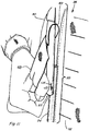
- covers 60 can be provided in generally covering relation to the longitudinal ends of clip 22, for capturing pin 24 therein and preventing inadvertent or unintended disassembly. When disassembly is desired, the cover 60 at the desired end can be manually moved out of covering relation to the end of the clip to allow passage of the pin.
- Suitable materials for covers 60 can include, but are not limited to, plastics or fabric, e.g., material available under the Hypalon tradename, natural or synthetic leather, or other material As another non-limiting example, as shown in FIGS.
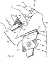
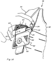
- flaps 62 and straps 54 can be provided with suitable detents, in the form of fasteners, such as hook and loop fasteners 64, and/or button snaps 66, engageable by folding or bending flap 62 into overlaying relation to the assembled apparatus 20 and the mating fastener element on strap 54, as denoted by arrow B in FIG. 14 , for holding it in the assembled state and preventing longitudinal relative movement of clip 22 and pin 24.
- fasteners such as hook and loop fasteners 64, and/or button snaps 66
- flaps 62 and straps 54 can be provided with suitable detents, in the form of fasteners, such as hook and loop fasteners 64, and/or button snaps 66, engageable by folding or bending flap 62 into overlaying relation to the assembled apparatus 20 and the mating fastener element on strap 54, as denoted by arrow B in FIG. 14 , for holding it in the assembled state and preventing longitudinal relative movement of clip 22 and pin 24.
- at least the disconnection of apparatus 20 should
- both of the C-clip 22 and pin 24 can be attached to the garment by common elements, such as straps, or sewed to the garment, riveted, and/or other well known attachment means. Either or both can also be covered with fabric material of the garment, as desired or required for a particular application, e.g., for camouflage purposes.
- clip 22 and pin 24 can be formed of a suitable rigid material such as a polyethylene, or engineered plastics material.
- the pin 24 can be of solid or tubular construction, as desired or required for a particular application.
- a garment can include one or more of the attachment and release apparatus 20 of the invention at a particular location, for connecting a particular element of the garment to another at that location.
- apparatus of the invention 20 can be provided along adjacent side edges, or at desired locations; along a belt; and on the front and rear panels for connecting them together for donning the vest 36.
- the vest 36 includes suspenders or shoulder straps 54
- apparatus 20 of the invention can be included at one or more of the desired connection locations on or between the shoulder strap or straps and the other element of the vest to be connected, such as the front or rear panels.
- the apparatus 20 of the invention can also be used for connecting other items to the garment, such as, but not limited to, pouches, canteens, radios, holsters, straps, additional protective panels or elements, and the like (not shown).
- the pin 24 of a first element of the garment is aligned with the end of the appropriate clip 22, and slid into the clip until fully received and detent element 38 engaged if provided.
- an alternative or additional detent element such as cover 60 or flap 62 is used, they are placed or positioned over the ends of the apparatus and engaged and the connection at that location is complete. Then one or more additional connections are made using additional apparatus 20 to completely connect the garment together in the desired configuration. For doffing, particularly for rapid release, the detent elements are withdrawn or opened, and the pin or pins 24 removed from the C-shape clip or clips 22 of the desired apparatus 20. One or more of apparatus 20 may be disconnected as desired or required for a particular situation.
Landscapes
- Engineering & Computer Science (AREA)
- Textile Engineering (AREA)
- General Engineering & Computer Science (AREA)
- Outer Garments And Coats (AREA)
- Professional, Industrial, Or Sporting Protective Garments (AREA)
Claims (7)
- Appareil d'assemblage et de libération (20) pour un vêtement, comprenant:un clip en C (22) définissant un canal (26) et une fente ouverte (32) s'étendant le long du canal (26), ouvert sur au moins une extrémité ouverte (28) du clip (22), et comprenant au moins un élément configuré pour attacher le clip en C (22) à un premier endroit sur le vêtement;une broche (24) pouvant être reçue par coulissement dans le canal (26) du clip en C (22) à travers l'extrémité ouverte (28) pour assembler le clip en C (22) et la broche (24), la broche (24) ayant une patte ou bande (34) réalisée pour s'étendre à travers la fente (32), pour attacher la broche (24) à un deuxième endroit sur le vêtement;au moins un élément à cliquet (38) associé au clip en C (22), pouvant être en prise par coopération avec la broche (24) pour retenir la broche (24) dans le canal (26), et libérable d'une manière prédéterminée pour permettre le retrait par coulissement de la broche (24) hors du canal (26) à travers l'extrémité ouverte (28), dans lequel le au moins un élément à cliquet (38) comprend une languette (40) s'étendant du clip en C (22), pouvant être mise en prise par coopération avec ou pouvant être reçue dans une encoche (42) dans la broche (24), et d'où on peut l'enlever dans un mouvement manuel de traction, dans lequel le clip en C (22) et la broche (24) sont allongés et la languette (40) est située autour d'une partie centrale du clip en C (22), dans lequel la fente (32) est suffisamment petite pour empêcher le passage de la broche (24) au travers.
- Appareil (20) selon la revendication 1, dans lequel le clip en C (22) et la broche (24) ont des surfaces (46, 48) qui se correspondent, liant le canal (26), adjacentes à au moins un côté de la fente (32), qui sont en biseau à moins d'un angle de 90 degrés par rapport à la fente (32) de sorte que quand la broche (24) est située dans le canal (28) et qu'une force est exercée contre la patte ou bande (34) dans une direction pour tirer la broche (24) vers ou à travers la fente (32), la surface (48) du clip (22) adjacente à la fente (32) sera attirée vers la fente (32) pour empêcher le passage de la broche (24) au travers.
- Appareil (20) selon la revendication 2, dans lequel le clip en C (22) et la broche (24) ont des surfaces (46, 48) qui se correspondent, liant le canal (26), adjacentes aux deux côtés de la fente (32).
- Appareil (20) selon l'une des revendications précédentes, dans lequel la languette (40) est dotée d'une fonction d'agrippement, comme une boucle ou une corde en tissu (44), pour faciliter l'agrippement manuel de la languette (40) et la tirer transversalement à distance de l'encoche (42) quand on souhaite libérer la broche (24).
- Appareil (20) selon la revendication 1, dans lequel le au moins un élément (38) à cliquet comprend un recouvrement (60) sur l'extrémité ou les extrémités, ouverte(s) du clip en C (22), qui peut être facilement agrippé et déplacé en utilisant au moins un doigt.
- Gilet pare-balle (36) comprenant l'appareil d'assemblage et de libération (20) selon l'une quelconque des revendications 1 à 5.
- Gilet pare-balle (36) selon la revendication 6, dans lequel le clip en C (22) de l'appareil d'assemblage et de libération (20) est attaché à un premier endroit du gilet pare-balle, et la broche (24) de l'appareil d'assemblage et de libération (20) est attachée à un deuxième endroit du gilet pare-balle.
Priority Applications (1)
| Application Number | Priority Date | Filing Date | Title |
|---|---|---|---|
| PL16192729T PL3136041T3 (pl) | 2011-11-18 | 2012-11-19 | Mechanizm i sposób montażu i zwalniania ubioru |
Applications Claiming Priority (3)
| Application Number | Priority Date | Filing Date | Title |
|---|---|---|---|
| US201161561802P | 2011-11-18 | 2011-11-18 | |
| EP12868096.4A EP2780656B1 (fr) | 2011-11-18 | 2012-11-19 | Appareil et procédé d'assemblage et de libération de vêtement |
| PCT/US2012/065854 WO2013119294A1 (fr) | 2011-11-18 | 2012-11-19 | Appareil et procédé d'assemblage et de libération de vêtement |
Related Parent Applications (1)
| Application Number | Title | Priority Date | Filing Date |
|---|---|---|---|
| EP12868096.4A Division EP2780656B1 (fr) | 2011-11-18 | 2012-11-19 | Appareil et procédé d'assemblage et de libération de vêtement |
Publications (2)
| Publication Number | Publication Date |
|---|---|
| EP3136041A1 EP3136041A1 (fr) | 2017-03-01 |
| EP3136041B1 true EP3136041B1 (fr) | 2020-03-25 |
Family
ID=48947884
Family Applications (2)
| Application Number | Title | Priority Date | Filing Date |
|---|---|---|---|
| EP12868096.4A Active EP2780656B1 (fr) | 2011-11-18 | 2012-11-19 | Appareil et procédé d'assemblage et de libération de vêtement |
| EP16192729.8A Active EP3136041B1 (fr) | 2011-11-18 | 2012-11-19 | Appareil et procédé d'assemblage et de libération de vêtement |
Family Applications Before (1)
| Application Number | Title | Priority Date | Filing Date |
|---|---|---|---|
| EP12868096.4A Active EP2780656B1 (fr) | 2011-11-18 | 2012-11-19 | Appareil et procédé d'assemblage et de libération de vêtement |
Country Status (8)
| Country | Link |
|---|---|
| US (2) | US10051984B2 (fr) |
| EP (2) | EP2780656B1 (fr) |
| DK (2) | DK3136041T3 (fr) |
| ES (2) | ES2798576T3 (fr) |
| LT (2) | LT2780656T (fr) |
| PL (2) | PL2780656T3 (fr) |
| PT (2) | PT2780656T (fr) |
| WO (1) | WO2013119294A1 (fr) |
Families Citing this family (34)
| Publication number | Priority date | Publication date | Assignee | Title |
|---|---|---|---|---|
| US9562746B2 (en) | 2007-10-08 | 2017-02-07 | Mku Pvt Ltd | Quickly releasable vest |
| US10316887B2 (en) * | 2012-01-18 | 2019-06-11 | Illinois Tool Works, Inc. | Locking connector assembly |
| US10281240B2 (en) * | 2013-01-14 | 2019-05-07 | FirstSpear, LLC | Modular armor supplement apparatus and system with silent fasteners and adjustability |
| RU2016114661A (ru) * | 2013-09-16 | 2017-10-23 | ЭмКейЮ ПВТ ЛТД | Жилет с возможностью быстрого отсоединения |
| IL231232A0 (en) * | 2014-02-27 | 2014-08-31 | Source Vagabond Systems Ltd | Quick release vest |
| US9766044B2 (en) * | 2014-03-28 | 2017-09-19 | Matscitechno Licensing Company | Protective system for carrying equipment |
| FR3021846B1 (fr) * | 2014-06-10 | 2017-11-24 | Protecop | Systeme de fixation pour un vetement |
| US11911673B2 (en) | 2015-03-02 | 2024-02-27 | Karsten Manufacturing Corporation | Golf bag with collapsable pocket assembly |
| US12508481B2 (en) | 2015-03-02 | 2025-12-30 | Karsten Manufacturing Corporation | Snap fit golf bag assembly |
| DE102015014471B3 (de) * | 2015-11-09 | 2017-02-23 | Lindnerhof-Taktik GmbH | Schließe |
| WO2017127385A1 (fr) | 2016-01-19 | 2017-07-27 | Safariland, Llc | Raccord à désaccouplement rapide |
| IT201700045764A1 (it) | 2017-04-27 | 2018-10-27 | Due Emme Srl | Dispositivo di sgancio rapido per articoli indossabili |
| US10314355B1 (en) * | 2017-11-30 | 2019-06-11 | Raine, INC. | Panel and system for load carriage and protection for tactical and non-tactical garments |
| US20190200572A1 (en) * | 2017-12-29 | 2019-07-04 | Central Lake Armor Express, Inc. | Canine ballistic carrier vest |
| CN208129613U (zh) * | 2018-01-22 | 2018-11-23 | 广州德谱皮具实业有限公司 | 一种皮带扣 |
| KR102087811B1 (ko) * | 2018-09-28 | 2020-03-11 | (주)보광아이엔티 | 착의와 탈의가 편리한 방호복 |
| GB2581125B (en) * | 2018-12-10 | 2022-09-21 | Warrior Assault Systems Ltd | A cummerbund |
| US11079203B2 (en) | 2019-03-22 | 2021-08-03 | Aardvark | Three-piece tactical cummerbund |
| GB2585342B (en) * | 2019-04-15 | 2021-10-27 | Crib Gogh Ltd | A buckle and a torso-protection system |
| US11779064B2 (en) * | 2019-08-16 | 2023-10-10 | Safariland, Llc | Adapter system for vest closure mechanisms |
| USD943834S1 (en) * | 2020-05-17 | 2022-02-15 | Helikon-Tex Grzegorz Mieszczak | Tactical vest |
| US11064771B1 (en) | 2020-08-21 | 2021-07-20 | Duraflex Hong Kong Limited | Connector system with quick release |
| US11564459B2 (en) | 2021-03-30 | 2023-01-31 | Central Lake Armor Express, Inc. | Buckle assembly |
| USD979849S1 (en) * | 2021-03-30 | 2023-02-28 | Central Lake Armor Express, Inc. | Ballistic carrier garment |
| USD979848S1 (en) * | 2021-03-30 | 2023-02-28 | Central Lake Armor Express, Inc. | Ballistic carrier garment |
| KR102499804B1 (ko) * | 2021-06-09 | 2023-02-14 | 주식회사 헤세드코리아 | 방탄복 |
| US12085369B2 (en) * | 2021-08-02 | 2024-09-10 | Angel Armor, Llc | Ballistic-resistant garment |
| PL438823A1 (pl) | 2021-08-26 | 2023-02-27 | Krzysztof Pędzisz | Szybkorozpinalna kamizelka ochronna, układ szybkiego zwalniania oraz klamra zatrzaskowa |
| USD1096508S1 (en) * | 2022-03-23 | 2025-10-07 | Point Blank Enterprises, Inc. | Magnetic buckle |
| CN217658440U (zh) | 2022-06-21 | 2022-10-28 | 陈盛 | 一种快速拆卸扣 |
| US12310427B2 (en) * | 2022-12-16 | 2025-05-27 | Fastech Asia Worldwide, Ltd. | Closure apparatus |
| US20240215694A1 (en) * | 2022-12-28 | 2024-07-04 | Anthony Joseph Lang | Hands-Free Umbrella Holder |
| USD1092292S1 (en) * | 2023-01-31 | 2025-09-09 | Central Lake Armored Express, Inc. | Buckle assembly |
| USD1076459S1 (en) * | 2024-09-16 | 2025-05-27 | Zijiang Yang | M.O.L.L.E. panel |
Family Cites Families (33)
| Publication number | Priority date | Publication date | Assignee | Title |
|---|---|---|---|---|
| US796414A (en) * | 1904-07-12 | 1905-08-08 | Herman E S Chayes | Suspenders. |
| GB663482A (en) | 1949-05-25 | 1951-12-19 | Frederick William James Cripps | Improvements in and relating to hair waving appliances |
| FR2290860A1 (fr) | 1974-11-15 | 1976-06-11 | Tarwil Rosoflex | Dispositif de fermeture servant a l'agrafage d'un soutien-gorge |
| US4054972A (en) * | 1976-04-27 | 1977-10-25 | Ross Fredrick Rowell | Brassiere fastener |
| GB2079359B (en) | 1980-06-25 | 1983-11-02 | Regent Autocar Co Ltd | Improvements in buckles |
| US4502191A (en) | 1983-05-06 | 1985-03-05 | Institut De Recherche En Sante Et En Securite Du Travail Du Quebec | Strap buckle |
| US4578843A (en) * | 1984-06-11 | 1986-04-01 | Hsc Corporation | Strap connector and method of making the same |
| US4777665A (en) | 1986-07-07 | 1988-10-18 | Osaka Necktie Hosei Kabushiki Kaisha | Quick-release necktie |
| JPH0510654Y2 (fr) * | 1987-04-13 | 1993-03-16 | ||
| DE68913371T2 (de) * | 1988-06-25 | 1994-10-06 | Robson Peter M | Profilierte Befestigungsvorrichtung. |
| US4935996A (en) | 1989-04-25 | 1990-06-26 | Ferrara Carl J | Combination hinge and clasp for jewelry |
| US5369854A (en) | 1993-07-01 | 1994-12-06 | Stephens; Bonnie S. | Necklace clasp |
| JP3522970B2 (ja) * | 1996-05-27 | 2004-04-26 | Ykk株式会社 | 連結具を備えた紐体 |
| US5671516A (en) | 1996-06-28 | 1997-09-30 | Sartori; Robert C. | Easy connect and release seat belt buckle |
| US6009604A (en) * | 1998-11-09 | 2000-01-04 | Fildan; Gerhard | Front closure for a brassiere |
| JP2001286309A (ja) * | 1999-11-16 | 2001-10-16 | Ykk Corp | 係止部材とその製造方法 |
| US7047570B2 (en) | 2003-07-08 | 2006-05-23 | Eagle Industries Unlimited, Inc. | Cut away vest |
| US7987523B2 (en) | 2003-07-08 | 2011-08-02 | Eagle Industries Unlimited, Inc. | Quick release garment |
| US7480967B2 (en) * | 2004-04-01 | 2009-01-27 | Fossil, Inc. | Removable fastener apparatus and method of use |
| US7238081B2 (en) | 2004-05-13 | 2007-07-03 | Fildan Accessories Corporation | Reversible shoulder strap for a garment, especially a brassiere |
| US8056296B2 (en) | 2006-04-07 | 2011-11-15 | General Electric Company | Methods and apparatus for assembling wind turbine towers |
| US7636989B2 (en) * | 2006-05-31 | 2009-12-29 | Illinois Tool Works Inc. | Press-to-open zippers for reclosable packages |
| US7814567B2 (en) * | 2006-06-09 | 2010-10-19 | First Choice Armor & Equipment, Inc. | Protective garment having a quick release system |
| US7905553B2 (en) * | 2007-04-05 | 2011-03-15 | Elaine Lichtner | Safety garment and method of using the same |
| US7979917B2 (en) | 2007-05-08 | 2011-07-19 | Survival Armor, Inc. | Rear break away ballistics vest |
| US20090094809A1 (en) | 2007-10-16 | 2009-04-16 | Nifco Taiwan Corporation | Buckle |
| CN101951801B (zh) | 2008-02-21 | 2012-11-28 | 费得洛克有限公司 | 带有负载保护的机械磁性连接结构 |
| US8056196B2 (en) | 2009-03-16 | 2011-11-15 | The United States Of America As Represented By The Secretary Of The Navy | Quick release fitting |
| KR101030366B1 (ko) * | 2009-04-18 | 2011-04-20 | 백지숙 | 스트랩 및 부속물의 연결장치 |
| US8201271B2 (en) * | 2009-11-19 | 2012-06-19 | Guardian Protective Technologies Inc. | Armor vest with mechanical quick release mechanism |
| KR101064014B1 (ko) * | 2010-01-16 | 2011-09-08 | 백지숙 | 스트랩 및 부속물의 연결장치 |
| US10316887B2 (en) | 2012-01-18 | 2019-06-11 | Illinois Tool Works, Inc. | Locking connector assembly |
| US11064771B1 (en) * | 2020-08-21 | 2021-07-20 | Duraflex Hong Kong Limited | Connector system with quick release |
-
2012
- 2012-11-19 LT LTEP12868096.4T patent/LT2780656T/lt unknown
- 2012-11-19 DK DK16192729.8T patent/DK3136041T3/da active
- 2012-11-19 WO PCT/US2012/065854 patent/WO2013119294A1/fr not_active Ceased
- 2012-11-19 DK DK12868096.4T patent/DK2780656T3/en active
- 2012-11-19 EP EP12868096.4A patent/EP2780656B1/fr active Active
- 2012-11-19 ES ES16192729T patent/ES2798576T3/es active Active
- 2012-11-19 LT LTEP16192729.8T patent/LT3136041T/lt unknown
- 2012-11-19 PL PL12868096T patent/PL2780656T3/pl unknown
- 2012-11-19 US US14/358,640 patent/US10051984B2/en active Active
- 2012-11-19 PT PT128680964T patent/PT2780656T/pt unknown
- 2012-11-19 PL PL16192729T patent/PL3136041T3/pl unknown
- 2012-11-19 PT PT161927298T patent/PT3136041T/pt unknown
- 2012-11-19 ES ES12868096.4T patent/ES2610577T3/es active Active
- 2012-11-19 EP EP16192729.8A patent/EP3136041B1/fr active Active
-
2018
- 2018-08-20 US US16/105,638 patent/US12349820B2/en active Active
Non-Patent Citations (1)
| Title |
|---|
| None * |
Also Published As
| Publication number | Publication date |
|---|---|
| PL3136041T3 (pl) | 2020-09-21 |
| ES2610577T3 (es) | 2017-04-28 |
| EP2780656A4 (fr) | 2015-05-06 |
| WO2013119294A1 (fr) | 2013-08-15 |
| ES2798576T3 (es) | 2020-12-11 |
| US20140332572A1 (en) | 2014-11-13 |
| LT2780656T (lt) | 2017-01-25 |
| US10051984B2 (en) | 2018-08-21 |
| PT2780656T (pt) | 2017-01-20 |
| PL2780656T3 (pl) | 2017-06-30 |
| LT3136041T (lt) | 2020-06-25 |
| DK2780656T3 (en) | 2017-01-23 |
| PT3136041T (pt) | 2020-06-23 |
| DK3136041T3 (da) | 2020-06-22 |
| EP2780656B1 (fr) | 2016-10-12 |
| EP2780656A1 (fr) | 2014-09-24 |
| US20190000252A1 (en) | 2019-01-03 |
| US12349820B2 (en) | 2025-07-08 |
| EP3136041A1 (fr) | 2017-03-01 |
Similar Documents
| Publication | Publication Date | Title |
|---|---|---|
| US12349820B2 (en) | Garment assembly and release apparatus and method | |
| EP3107628B1 (fr) | Connecteur | |
| US8826462B2 (en) | Releasable vest | |
| US8898814B2 (en) | Releasable vest | |
| US8418265B1 (en) | Releasable vest | |
| US8595862B2 (en) | Releasable vest | |
| US9746284B2 (en) | Quick conversion sling | |
| AU2016201891B2 (en) | Quick release garment | |
| US12220024B2 (en) | Buckle | |
| US20180310673A1 (en) | Rapid release device for wearable articles | |
| US20160202023A1 (en) | Cutaway Vest | |
| EP3043667B1 (fr) | Gilet se retirant rapidement | |
| EP3496976B1 (fr) | Système et procédé de ceinture de sécurité recevant un équipement | |
| US20180043856A1 (en) | Tactical-gear-accommodating seatbelt system and method | |
| EP4289306A1 (fr) | Clip à dégagement rapide | |
| US20260063394A1 (en) | Plate carrier system | |
| GB2534189A (en) | Releasable fastenings |
Legal Events
| Date | Code | Title | Description |
|---|---|---|---|
| PUAI | Public reference made under article 153(3) epc to a published international application that has entered the european phase |
Free format text: ORIGINAL CODE: 0009012 |
|
| STAA | Information on the status of an ep patent application or granted ep patent |
Free format text: STATUS: THE APPLICATION HAS BEEN PUBLISHED |
|
| AC | Divisional application: reference to earlier application |
Ref document number: 2780656 Country of ref document: EP Kind code of ref document: P |
|
| AK | Designated contracting states |
Kind code of ref document: A1 Designated state(s): AL AT BE BG CH CY CZ DE DK EE ES FI FR GB GR HR HU IE IS IT LI LT LU LV MC MK MT NL NO PL PT RO RS SE SI SK SM TR |
|
| RIN1 | Information on inventor provided before grant (corrected) |
Inventor name: BUERCK, TREVOR, S. Inventor name: CARVER, SCOTT, J. Inventor name: COLE, MICHAEL, E. |
|
| STAA | Information on the status of an ep patent application or granted ep patent |
Free format text: STATUS: REQUEST FOR EXAMINATION WAS MADE |
|
| 17P | Request for examination filed |
Effective date: 20170901 |
|
| RBV | Designated contracting states (corrected) |
Designated state(s): AL AT BE BG CH CY CZ DE DK EE ES FI FR GB GR HR HU IE IS IT LI LT LU LV MC MK MT NL NO PL PT RO RS SE SI SK SM TR |
|
| STAA | Information on the status of an ep patent application or granted ep patent |
Free format text: STATUS: EXAMINATION IS IN PROGRESS |
|
| 17Q | First examination report despatched |
Effective date: 20180322 |
|
| TPAC | Observations filed by third parties |
Free format text: ORIGINAL CODE: EPIDOSNTIPA |
|
| GRAP | Despatch of communication of intention to grant a patent |
Free format text: ORIGINAL CODE: EPIDOSNIGR1 |
|
| STAA | Information on the status of an ep patent application or granted ep patent |
Free format text: STATUS: GRANT OF PATENT IS INTENDED |
|
| INTG | Intention to grant announced |
Effective date: 20191024 |
|
| GRAS | Grant fee paid |
Free format text: ORIGINAL CODE: EPIDOSNIGR3 |
|
| GRAA | (expected) grant |
Free format text: ORIGINAL CODE: 0009210 |
|
| STAA | Information on the status of an ep patent application or granted ep patent |
Free format text: STATUS: THE PATENT HAS BEEN GRANTED |
|
| AC | Divisional application: reference to earlier application |
Ref document number: 2780656 Country of ref document: EP Kind code of ref document: P |
|
| AK | Designated contracting states |
Kind code of ref document: B1 Designated state(s): AL AT BE BG CH CY CZ DE DK EE ES FI FR GB GR HR HU IE IS IT LI LT LU LV MC MK MT NL NO PL PT RO RS SE SI SK SM TR |
|
| REG | Reference to a national code |
Ref country code: GB Ref legal event code: FG4D |
|
| REG | Reference to a national code |
Ref country code: AT Ref legal event code: REF Ref document number: 1249050 Country of ref document: AT Kind code of ref document: T Effective date: 20200415 Ref country code: IE Ref legal event code: FG4D |
|
| REG | Reference to a national code |
Ref country code: DE Ref legal event code: R096 Ref document number: 602012068833 Country of ref document: DE |
|
| REG | Reference to a national code |
Ref country code: CH Ref legal event code: NV Representative=s name: TROESCH SCHEIDEGGER WERNER AG, CH |
|
| REG | Reference to a national code |
Ref country code: FI Ref legal event code: FGE |
|
| REG | Reference to a national code |
Ref country code: DK Ref legal event code: T3 Effective date: 20200618 |
|
| REG | Reference to a national code |
Ref country code: PT Ref legal event code: SC4A Ref document number: 3136041 Country of ref document: PT Date of ref document: 20200623 Kind code of ref document: T Free format text: AVAILABILITY OF NATIONAL TRANSLATION Effective date: 20200616 |
|
| REG | Reference to a national code |
Ref country code: SE Ref legal event code: TRGR |
|
| PG25 | Lapsed in a contracting state [announced via postgrant information from national office to epo] |
Ref country code: RS Free format text: LAPSE BECAUSE OF FAILURE TO SUBMIT A TRANSLATION OF THE DESCRIPTION OR TO PAY THE FEE WITHIN THE PRESCRIBED TIME-LIMIT Effective date: 20200325 |
|
| REG | Reference to a national code |
Ref country code: NO Ref legal event code: T2 Effective date: 20200325 |
|
| PG25 | Lapsed in a contracting state [announced via postgrant information from national office to epo] |
Ref country code: HR Free format text: LAPSE BECAUSE OF FAILURE TO SUBMIT A TRANSLATION OF THE DESCRIPTION OR TO PAY THE FEE WITHIN THE PRESCRIBED TIME-LIMIT Effective date: 20200325 Ref country code: BG Free format text: LAPSE BECAUSE OF FAILURE TO SUBMIT A TRANSLATION OF THE DESCRIPTION OR TO PAY THE FEE WITHIN THE PRESCRIBED TIME-LIMIT Effective date: 20200625 Ref country code: GR Free format text: LAPSE BECAUSE OF FAILURE TO SUBMIT A TRANSLATION OF THE DESCRIPTION OR TO PAY THE FEE WITHIN THE PRESCRIBED TIME-LIMIT Effective date: 20200626 |
|
| REG | Reference to a national code |
Ref country code: NL Ref legal event code: MP Effective date: 20200325 |
|
| PG25 | Lapsed in a contracting state [announced via postgrant information from national office to epo] |
Ref country code: NL Free format text: LAPSE BECAUSE OF FAILURE TO SUBMIT A TRANSLATION OF THE DESCRIPTION OR TO PAY THE FEE WITHIN THE PRESCRIBED TIME-LIMIT Effective date: 20200325 |
|
| PG25 | Lapsed in a contracting state [announced via postgrant information from national office to epo] |
Ref country code: EE Free format text: LAPSE BECAUSE OF FAILURE TO SUBMIT A TRANSLATION OF THE DESCRIPTION OR TO PAY THE FEE WITHIN THE PRESCRIBED TIME-LIMIT Effective date: 20200325 Ref country code: SM Free format text: LAPSE BECAUSE OF FAILURE TO SUBMIT A TRANSLATION OF THE DESCRIPTION OR TO PAY THE FEE WITHIN THE PRESCRIBED TIME-LIMIT Effective date: 20200325 Ref country code: CZ Free format text: LAPSE BECAUSE OF FAILURE TO SUBMIT A TRANSLATION OF THE DESCRIPTION OR TO PAY THE FEE WITHIN THE PRESCRIBED TIME-LIMIT Effective date: 20200325 Ref country code: IS Free format text: LAPSE BECAUSE OF FAILURE TO SUBMIT A TRANSLATION OF THE DESCRIPTION OR TO PAY THE FEE WITHIN THE PRESCRIBED TIME-LIMIT Effective date: 20200725 Ref country code: SK Free format text: LAPSE BECAUSE OF FAILURE TO SUBMIT A TRANSLATION OF THE DESCRIPTION OR TO PAY THE FEE WITHIN THE PRESCRIBED TIME-LIMIT Effective date: 20200325 Ref country code: RO Free format text: LAPSE BECAUSE OF FAILURE TO SUBMIT A TRANSLATION OF THE DESCRIPTION OR TO PAY THE FEE WITHIN THE PRESCRIBED TIME-LIMIT Effective date: 20200325 |
|
| REG | Reference to a national code |
Ref country code: AT Ref legal event code: MK05 Ref document number: 1249050 Country of ref document: AT Kind code of ref document: T Effective date: 20200325 |
|
| REG | Reference to a national code |
Ref country code: ES Ref legal event code: FG2A Ref document number: 2798576 Country of ref document: ES Kind code of ref document: T3 Effective date: 20201211 |
|
| REG | Reference to a national code |
Ref country code: DE Ref legal event code: R097 Ref document number: 602012068833 Country of ref document: DE |
|
| PG25 | Lapsed in a contracting state [announced via postgrant information from national office to epo] |
Ref country code: AT Free format text: LAPSE BECAUSE OF FAILURE TO SUBMIT A TRANSLATION OF THE DESCRIPTION OR TO PAY THE FEE WITHIN THE PRESCRIBED TIME-LIMIT Effective date: 20200325 |
|
| PLBE | No opposition filed within time limit |
Free format text: ORIGINAL CODE: 0009261 |
|
| STAA | Information on the status of an ep patent application or granted ep patent |
Free format text: STATUS: NO OPPOSITION FILED WITHIN TIME LIMIT |
|
| 26N | No opposition filed |
Effective date: 20210112 |
|
| PG25 | Lapsed in a contracting state [announced via postgrant information from national office to epo] |
Ref country code: SI Free format text: LAPSE BECAUSE OF FAILURE TO SUBMIT A TRANSLATION OF THE DESCRIPTION OR TO PAY THE FEE WITHIN THE PRESCRIBED TIME-LIMIT Effective date: 20200325 |
|
| PG25 | Lapsed in a contracting state [announced via postgrant information from national office to epo] |
Ref country code: MC Free format text: LAPSE BECAUSE OF FAILURE TO SUBMIT A TRANSLATION OF THE DESCRIPTION OR TO PAY THE FEE WITHIN THE PRESCRIBED TIME-LIMIT Effective date: 20200325 |
|
| PG25 | Lapsed in a contracting state [announced via postgrant information from national office to epo] |
Ref country code: LU Free format text: LAPSE BECAUSE OF NON-PAYMENT OF DUE FEES Effective date: 20201119 |
|
| PG25 | Lapsed in a contracting state [announced via postgrant information from national office to epo] |
Ref country code: TR Free format text: LAPSE BECAUSE OF FAILURE TO SUBMIT A TRANSLATION OF THE DESCRIPTION OR TO PAY THE FEE WITHIN THE PRESCRIBED TIME-LIMIT Effective date: 20200325 Ref country code: MT Free format text: LAPSE BECAUSE OF FAILURE TO SUBMIT A TRANSLATION OF THE DESCRIPTION OR TO PAY THE FEE WITHIN THE PRESCRIBED TIME-LIMIT Effective date: 20200325 Ref country code: CY Free format text: LAPSE BECAUSE OF FAILURE TO SUBMIT A TRANSLATION OF THE DESCRIPTION OR TO PAY THE FEE WITHIN THE PRESCRIBED TIME-LIMIT Effective date: 20200325 |
|
| PG25 | Lapsed in a contracting state [announced via postgrant information from national office to epo] |
Ref country code: MK Free format text: LAPSE BECAUSE OF FAILURE TO SUBMIT A TRANSLATION OF THE DESCRIPTION OR TO PAY THE FEE WITHIN THE PRESCRIBED TIME-LIMIT Effective date: 20200325 Ref country code: AL Free format text: LAPSE BECAUSE OF FAILURE TO SUBMIT A TRANSLATION OF THE DESCRIPTION OR TO PAY THE FEE WITHIN THE PRESCRIBED TIME-LIMIT Effective date: 20200325 |
|
| REG | Reference to a national code |
Ref country code: CH Ref legal event code: U11 Free format text: ST27 STATUS EVENT CODE: U-0-0-U10-U11 (AS PROVIDED BY THE NATIONAL OFFICE) Effective date: 20251201 |
|
| PGFP | Annual fee paid to national office [announced via postgrant information from national office to epo] |
Ref country code: PT Payment date: 20251124 Year of fee payment: 14 |
|
| PGFP | Annual fee paid to national office [announced via postgrant information from national office to epo] |
Ref country code: DE Payment date: 20251120 Year of fee payment: 14 |
|
| PGFP | Annual fee paid to national office [announced via postgrant information from national office to epo] |
Ref country code: LT Payment date: 20251120 Year of fee payment: 14 Ref country code: GB Payment date: 20251127 Year of fee payment: 14 |
|
| PGFP | Annual fee paid to national office [announced via postgrant information from national office to epo] |
Ref country code: NO Payment date: 20251201 Year of fee payment: 14 |
|
| PGFP | Annual fee paid to national office [announced via postgrant information from national office to epo] |
Ref country code: IT Payment date: 20251127 Year of fee payment: 14 Ref country code: FI Payment date: 20251127 Year of fee payment: 14 Ref country code: DK Payment date: 20251127 Year of fee payment: 14 |
|
| PGFP | Annual fee paid to national office [announced via postgrant information from national office to epo] |
Ref country code: FR Payment date: 20251127 Year of fee payment: 14 |
|
| PGFP | Annual fee paid to national office [announced via postgrant information from national office to epo] |
Ref country code: BE Payment date: 20251127 Year of fee payment: 14 |
|
| PGFP | Annual fee paid to national office [announced via postgrant information from national office to epo] |
Ref country code: SE Payment date: 20251127 Year of fee payment: 14 Ref country code: CH Payment date: 20251201 Year of fee payment: 14 |
|
| PGFP | Annual fee paid to national office [announced via postgrant information from national office to epo] |
Ref country code: IE Payment date: 20251127 Year of fee payment: 14 |
|
| PGFP | Annual fee paid to national office [announced via postgrant information from national office to epo] |
Ref country code: LV Payment date: 20251120 Year of fee payment: 14 |
|
| PGFP | Annual fee paid to national office [announced via postgrant information from national office to epo] |
Ref country code: PL Payment date: 20251126 Year of fee payment: 14 |
|
| PGFP | Annual fee paid to national office [announced via postgrant information from national office to epo] |
Ref country code: ES Payment date: 20251201 Year of fee payment: 14 |