EP3136149B1 - Système d'observation et d'éclairage pour un microscope ophtalmique, microscope ophtalmique comprenant un tel système et procédé de microscopie - Google Patents
Système d'observation et d'éclairage pour un microscope ophtalmique, microscope ophtalmique comprenant un tel système et procédé de microscopie Download PDFInfo
- Publication number
- EP3136149B1 EP3136149B1 EP15182105.5A EP15182105A EP3136149B1 EP 3136149 B1 EP3136149 B1 EP 3136149B1 EP 15182105 A EP15182105 A EP 15182105A EP 3136149 B1 EP3136149 B1 EP 3136149B1
- Authority
- EP
- European Patent Office
- Prior art keywords
- illumination
- coaxial
- intensity
- observation
- observation pupil
- Prior art date
- Legal status (The legal status is an assumption and is not a legal conclusion. Google has not performed a legal analysis and makes no representation as to the accuracy of the status listed.)
- Active
Links
Images

Classifications
-
- G—PHYSICS
- G02—OPTICS
- G02B—OPTICAL ELEMENTS, SYSTEMS OR APPARATUS
- G02B21/00—Microscopes
- G02B21/06—Means for illuminating specimens
- G02B21/08—Condensers
- G02B21/082—Condensers for incident illumination only
-
- A—HUMAN NECESSITIES
- A61—MEDICAL OR VETERINARY SCIENCE; HYGIENE
- A61B—DIAGNOSIS; SURGERY; IDENTIFICATION
- A61B3/00—Apparatus for testing the eyes; Instruments for examining the eyes
- A61B3/10—Objective types, i.e. instruments for examining the eyes independent of the patients' perceptions or reactions
- A61B3/13—Ophthalmic microscopes
- A61B3/132—Ophthalmic microscopes in binocular arrangement
-
- A—HUMAN NECESSITIES
- A61—MEDICAL OR VETERINARY SCIENCE; HYGIENE
- A61B—DIAGNOSIS; SURGERY; IDENTIFICATION
- A61B3/00—Apparatus for testing the eyes; Instruments for examining the eyes
- A61B3/10—Objective types, i.e. instruments for examining the eyes independent of the patients' perceptions or reactions
- A61B3/14—Arrangements specially adapted for eye photography
- A61B3/15—Arrangements specially adapted for eye photography with means for aligning, spacing or blocking spurious reflection ; with means for relaxing
- A61B3/152—Arrangements specially adapted for eye photography with means for aligning, spacing or blocking spurious reflection ; with means for relaxing for aligning
-
- G—PHYSICS
- G02—OPTICS
- G02B—OPTICAL ELEMENTS, SYSTEMS OR APPARATUS
- G02B21/00—Microscopes
- G02B21/0004—Microscopes specially adapted for specific applications
- G02B21/0012—Surgical microscopes
-
- G—PHYSICS
- G02—OPTICS
- G02B—OPTICAL ELEMENTS, SYSTEMS OR APPARATUS
- G02B21/00—Microscopes
- G02B21/18—Arrangements with more than one light path, e.g. for comparing two specimens
- G02B21/20—Binocular arrangements
- G02B21/22—Stereoscopic arrangements
-
- A—HUMAN NECESSITIES
- A61—MEDICAL OR VETERINARY SCIENCE; HYGIENE
- A61F—FILTERS IMPLANTABLE INTO BLOOD VESSELS; PROSTHESES; DEVICES PROVIDING PATENCY TO, OR PREVENTING COLLAPSING OF, TUBULAR STRUCTURES OF THE BODY, e.g. STENTS; ORTHOPAEDIC, NURSING OR CONTRACEPTIVE DEVICES; FOMENTATION; TREATMENT OR PROTECTION OF EYES OR EARS; BANDAGES, DRESSINGS OR ABSORBENT PADS; FIRST-AID KITS
- A61F9/00—Methods or devices for treatment of the eyes; Devices for putting in contact-lenses; Devices to correct squinting; Apparatus to guide the blind; Protective devices for the eyes, carried on the body or in the hand
- A61F9/007—Methods or devices for eye surgery
Definitions
- the invention relates to a microscope for performing eye surgery, the microscope comprising an illumination and observation system, wherein the illumination and observation system comprises a first and second observation pupil for the eyes of an observer such as an assistant, a coaxial illumination in the first observation pupil only, the coaxial illumination being adapted to generate a red reflex in the observed eye in operation.
- the illumination and observation system comprises a first and second observation pupil for the eyes of an observer such as an assistant, a coaxial illumination in the first observation pupil only, the coaxial illumination being adapted to generate a red reflex in the observed eye in operation.
- the invention further relates to a microscopying method by using a coaxial illumination to illuminate the object coaxially through a first observation pupil only and by using a main illumination to illuminate the object with a larger field of illumination in the object plane than the coaxial illumination only.
- Ophthalmic microscopes i.e. microscopes that are used for eye surgery, comprise typically two different kinds of illumination.
- a first illumination serves to illuminate a rather large field of illumination in the observed object, i.e. the eye to be operated, in particular in the object plane. This illumination lightens the surroundings of the area, where the actual observation takes place.
- the field of illumination of this type of illumination has typically a diameter between 60 mm and 80 mm. This illumination is referred to in the following as a main illumination.
- the main illumination is primarily used to visualize outer eye structures like the cornea.
- a second type of illumination makes use of the characteristic of the eye's retina to provide a reddish-orange reflection of light called the red reflex.
- the red reflex offers much higher contrasts than the main illumination and is mainly used for cataract surgery.
- the red reflex is generated by an illumination, which is coaxial or at least closely coaxial, e.g. within +/- 5°, to the axis of an observer's pupil which looks through the illumination and observation system onto the observed eye.
- a known system for generating a red reflex is, for example, described in EP 0 661 020 B1 .
- the field of illumination of the coaxial illumination is usually much smaller than the diameter of the main illumination, e.g. by a factor 2 to 5.
- a stereoscopic microscope for eye surgery using a single light source for producing coaxial illumination in two observation pupils is known from EP 1 455 215 A2 .
- a main illumination is provided in the second observation pupil only, the main illumination having a larger field of illumination in the object plane than the coaxial illumination and a control subsystem is provided which is adapted to automatically adjust an intensity of the main illumination depending on a change in an intensity of the coaxial illumination.
- the intensity of the main illumination is controlled to automatically follow the intensity of the coaxial illumination.
- the main illumination and the coaxial illumination are provided by separate light sources.
- a red reflex can be generated in the second observation pupil.
- the operation of the illumination and observation system or the microscope is facilitated, as the main illumination is automatically adapted to any change of the coaxial illumination. If the coaxial illumination is adapted to produce a stronger red reflex, the main illumination also gets stronger and contrast is maintained.
- Second, by coupling the intensity of the main illumination to the intensity of the coaxial illumination it is possible that an intensity of the red reflex in the second observation pupil, which in most cases is invariably generated also by the main illumination, follows the intensity of the red reflex generated by the coaxial illumination.
- the inventive solution has the advantage that a stereoscopic red reflex can be maintained without the need to include another expensive coaxial illumination.
- the intensity may be easily measured at the plane of observation in the observed eye, e.g. in the SI unit lux, either as the intensity reflected from the observed object or as the intensity incident on the observed eye. For the purposes of this invention, even a subjective impression of a typical observation without an objective measurement of the intensity may be sufficient.
- the solution according to the invention may be further improved by the following features, which may be combined independently of one another.
- the controlled subsystem may be adapted to set a ratio of the intensity of the main illumination to the intensity of the coaxial illumination at a target ratio independent of a change in the intensity of the coaxial illumination.
- a preferred target ratio is in a range of 0.2 to 5, particularly preferable in a range of 0.5 to 2, even more preferable in a range of 0.5 to 1.5 measured in lux.
- the target ratio is selected such that the intensity of the red reflex in the first observation pupil is perceived to be identical or almost identical to the intensity of the red reflex in the second observation pupil.
- the target ratio may be independent of the intensity of the main illumination and/or the coaxial illumination and e.g. be factory-preset.
- the target ratio according to another embodiment may also vary linearly or non-linearly depending on the intensity of the main illumination and/or the coaxial illumination.
- the illumination and observation system may be configured to provide a user-adjustable target ratio.
- a manipulator subsystem including for example mechanical manipulators such as knobs and sliders and/or software-implemented manipulators such as virtual knobs or sliders on a computer screen, may be provided.
- a memory subsystem may be provided, which is adapted to store the target ratio.
- the target ratio may be stored adjustable.
- the memory subsystem can comprise mechanical parts such as a mechanical manipulator the position of which sets and stores the target ratio.
- the memory subsystem may also comprise electronic memory, such as a digital memory, for storing the target ratio in digital and/or analog form.
- the manipulator subsystem may further be adapted to change the intensity of at least one of the main and the coaxial illumination, for example by usage of one of the above-mentioned manipulators.
- the manipulator subsystem may be adapted to interact with at least one of the control subsystem and the memory subsystem to change the target ratio upon a manual input from an observer.
- the main illumination overlaps at least 50% with the second observation pupil.
- the intensity of the red reflex can be improved if the main illumination overlaps the optical axis of the second observation pupil.
- An improvement of the red reflex may also result from a main illumination, which is coaxial within +/- 5° to the optical axis of the second observation pupil.
- the illumination and observation system may further comprise a third and a fourth observation pupil, each of which is provided with a coaxial illumination.
- the third and fourth observation pupil may, in particular, be adapted to be used by a second observer, in particular a surgeon, whereas the first and second observation pupil may in particular be dedicated to an assistant or student assisting the surgeon during operation.
- the intensities of the coaxial illumination in the third and fourth observation pupil are preferably coupled to each other.
- the illumination and observation system may be adapted to allow a decoupling of the intensities of the coaxial illumination of the third and fourth observation pupil.
- at least one of the intensity of the coaxial illumination in the third observation pupil and the intensity of the coaxial illumination in the fourth observation pupil may be changed independently of each other.
- a subsequent coupling of the intensity of the coaxial illumination of the third and fourth observation pupil may maintain the ratio of the intensities of the coaxial illumination of the third and fourth observation pupil as it has been adjusted during the decoupling.
- the adjustment may be realized by the manipulator subsystem and by providing a storage subsystem which is adapted to store a ratio of the intensity of the coaxial illumination in the third and fourth observation pupil, and by the control subsystem to control the coaxial illumination in the third and fourth observation system during operation to maintain this ratio.
- the manipulator subsystem may be adapted to switch the illumination and observation system from a coupled state, in which the intensity of the main illumination is coupled to the intensity of the coaxial illumination in at least one of the first, third and fourth observation pupil, to a decoupled state, in which the intensity of the coaxial illumination in at least one of the first, third or fourth observation pupil is decoupled from the intensity of the main illumination.
- the switching from the coupled state to the decoupled state and the switching back from the decoupled to the coupled state may be performed upon manual input.
- the manipulator subsystem may be adapted to adjust the relative intensities of the main illumination in the second observation pupil and the coaxial illumination in at least one of the other observation pupils independent from one another.
- the main illumination and the coaxial illumination of at least one of the first, third or fourth observation pupil have separate light sources.
- the control subsystem may be adapted to control the energy input to the separate light sources individually, at least in the decoupled state.
- the light source of the main illumination In the coupled state, the light source of the main illumination may be operatively coupled to at least one of the light sources for the coaxial illumination.
- the coaxial illumination overlaps at least one of the first, third and fourth observation pupil by at least 50% and/or covers the optical axis of the respective observation pupil.
- each of the coaxial illuminations and the main illumination overlaps at least 50% of the first, second, third and fourth observation pupil.
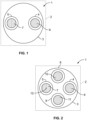
- Figure 1 shows a schematic plan view of a main objective lens 3 with a first observation pupil 4 and a second observation pupil 5.
- the first observation pupil 4 and the second observation pupil 5 are preferably for an assistant or a student assisting in e.g. eye surgery.
- a coaxial illumination 6 is directed through the first observation pupil 4, whereas a main illumination 7 is directed through the second observation pupil 5.
- a coaxial illumination 6 is directed through the first observation pupil 4, whereas a main illumination 7 is directed through the second observation pupil 5.
- the set up shown in Figure 1 is particularly useful for microscopes 2 which are used in eye surgery, i.e. so-called ophthalmic microscopes.
- the main illumination 7 At the observed object, i.e. in the object plane, in such a case the eye to be operated upon, the main illumination 7 generates a field of illumination which has a larger diameter in the observation plane than the coaxial illumination 6.
- the field of illumination may be between 60 mm and 80 mm.
- the axis of the coaxial illumination 6 deviates only slightly from the optical axis of the first observation pupil 4, e.g. by less than +/-5°.
- the main illumination 7 is also arranged to be coaxial at least within +/- 5 % to the optical axis of the second observation pupil 5.
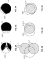
- both the main illumination 7 and the coaxial illumination 6 are able to generate a red reflex during eye surgery.
- the main illumination 7 and the coaxial illumination 6 overlap the respective observation pupil 5, 6 at least by 50 % with regard to its area.
- the intensity of the main illumination should be kept at a certain target ratio to the intensity of the coaxial illumination.
- a preferred intensity target ratio is in a range of 0.2 to 5, particularly preferable in a range of 0.5 to 2, even more preferable in a range of 0.5 to 1.5 measured in lux.
- the target ratio of the intensity of the main illumination to the coaxial illumination is maintained by the illumination and observation system 1 independently of the intensity of the coaxial illumination 6.
- the intensity of the main illumination 7 may be coupled to the intensity of the coaxial illumination 6: if the intensity of the coaxial illumination 6 changes, e.g. by manual operation of a user, the intensity of the main illumination 7 follows to maintain the same intensity ratio of the red reflex in both observation pupils 4, 5.
- the observation illumination system shown in Figure 1 may be expanded to comprise a third observation pupil 8 and a fourth observation pupil 9, each of which is provided with a respective coaxial illumination 10, 11, which may substantially correspond to the coaxial illumination of the first observation pupil 4.
- the third and fourth observation pupil 8, 9 may be specifically used by a surgeon.
- the coaxial illuminations 10, 11 are preferably identical, comprising identical and/or identically arranged optical elements, to produce an identical red reflex in the observed eye for both observation pupils 8, 9.
- the intensity of the coaxial illumination 6 for the first observation pupil 4 may be coupled to the intensity of at least one of the coaxial illumination 10 in the third observation pupil 8 and the coaxial illumination 11 in the fourth observation pupil 9. If the surgeon adjusts the intensity of the coaxial illumination 10, 11, the intensity of the coaxial illumination 6 in the first observation pupil 4 will automatically follow. Due to the coupling of the main illumination 7 in the second observation pupil 5 to the intensity of the coaxial illumination 6 in the first observation pupil 4, the intensity of the main illumination 7 will thus automatically follow any adjustment of the coaxial illumination 10, 11 in the third and fourth observation pupil 8, 9.
- the coaxial illumination 10 overlaps the third observation pupil 8 by more than 50 % and the coaxial illumination 11 overlaps the fourth observation pupil 9 by more than 50 %. Moreover, a red reflex is generated in all four observation pupils 4, 5, 8, 9. According to the invention, due to a coaxial alignment of the main illumination, a strong red reflex can be generated in the second observation pupil 5 without the need to install an expensive coaxial illumination. Rather, the main illumination 7 is aligned with the optical axis 12 of the second observation pupil 5 and its intensity is maintained at the target ratio to the intensity of the coaxial illumination in the first observation pupil 4.
- Figure 6 shows a schematic side view of parts of the illumination and observation system 1 as used in the microscope 2.
- the illuminations 6, 7, 10, 11 are aligned with and directed through the respective observation pupil 4, 5, 8, 9 by using beam splitters 14, 15.
- a larger beam splitter 14 is used to deflect the main illumination 7 for the second observation pupil 5 and the coaxial illuminations 10, 11 for the third and fourth observation pupil 8, 9 respectively.
- a second, smaller beam splitter 15 is used to deflect the coaxial illumination 6 for the first observation pupil 4.
- Each of the illuminations 6, 7, 10, 11 is preferably provided with a separate light source 16, which in particular may be an LED 17.
- a separate light source 16 which in particular may be an LED 17.
- the third and fourth observation pupil 8, 9 together with the respective coaxial illuminations 10, 11 are located right behind each other, only one light source 16 is shown for these two coaxial illuminations 10, 11.
- the beam splitters 14, 15 results in a very good alignment, not only of the coaxial illuminations 6, 10, 11 with the optical axes 12 of the first, third and fourth observation pupil 4, 8, 9, but also of the main illumination 7 with the optical axis 12 of the second observation pupil 5.
- optical elements such as lenses 18 for the coaxial illumination 6, 10, 11 and 19 for the main illumination 7 may be arranged.
- the optical elements 18, 19 may also comprise an aperture which may be adjustable.
- Figure 7 the embodiment of Figure 6 is shown in a schematic perspective view. From this, it can be seen that there is a single optical element 18 such as a lens associated with the three separate light sources 17 for the coaxial illuminations 6, 10, 11.
- the illumination and observation system 1 may have an identical design along the illumination paths 20 of the coaxial illuminations 6, 10, 11, so that the coaxial illuminations 6, 10, 11 in the first, third and observation pupil 4, 8, 9 have identical or at least almost identical properties.
- the light sources 16 may be arranged geometrically in a pattern that corresponds to the pattern of the observation pupils 4, 8, 9 which are equipped with coaxial illumination 6, 10, 11.
- the light sources 16 for generating the coaxial illumination 7, 10, 11 may be adapted to be controlled independently of each other or they may be coupled to each other.
- a control subsystem 21 is adapted to control the intensity of the light sources 16 for the coaxial illumination 6, 10, 11.
- the control subsystem 21 may be adapted to couple the coaxial illumination of the third and fourth observation pupil 8, 9 to the coaxial illumination 6 of the first observation pupil 4 and the main illumination 7 of the second observation pupil 5.
- the coupling can be implemented in the control subsystem 21 using a non-linear or linear coupling characteristic 22.
- the characteristic 22 can further be implemented by using a simple constant in the form of a target ratio.
- a linear or non-linear coupling characteristic may be used to adapt intensity changes better to any intensity-dependent characteristic of perception in the observer's eyes.
- the coupling can be implemented mechanically, e.g. by mechanically transmitting a motion from one manipulator to another via gears.
- the coupling can also be implemented electrically by using analog electric components such as amplifiers, resistor networks and capacities to arrive at the desired dependency of the main illumination 7 from at least one of the coaxial illuminations 6, 10, 11.
- a digital control may be used, wherein the coupling characteristic 22 may be, e.g. stored as a look-up table.
- the coupling characteristic 22 may be stored in a memory subsystem 23, which may comprise mechanical, electric, analog and/or digital components.
- the coupling characteristic 22 is just a target ratio of the main illumination 7 to at least one of the coaxial illuminations 6, 10 and/or 11 which is maintained by the control subsystem 21 if the intensity in one of the coaxial illumination 6, 10, 11 changes.
- a change in the intensity may be effected by operation of a manipulator subsystem 24.
- the manipulator subsystem 24 may comprise manually operable manipulators such as adjustment knobs or sliders, and/or electric elements such as adjustable resistors, gates or logical circuits in order to change the intensity of at least one, preferably each of the light sources 16.
- the manipulator subsystem 24 may also comprise software-implemented manipulators such as virtual sliders or adjustment knobs which are displayed on a computer screen for interaction with a user.
- two manipulator elements 25 are shown just by way of example.
- One of the manipulator elements 25 can be activated to control the intensity of the light source 16 of the main illumination 7.
- the other manipulator element 25 serves to adjust commonly the intensity of all three light sources 16 for the coaxial illuminations 6, 10, 11.
- a switch 26 may be provided as part of the manipulator subsystem 24 to activate a subset of the manipulator elements 25 and/or to switch the illumination and observation system 1 from a coupled state, in which the main illumination 7 is coupled to at least one of the coaxial illumination 6, 10 and 11, to a decoupled state, in which this coupling is released and the intensities of these illuminations can be adjusted independently. It is preferred that upon switching from a decoupled to the coupled state, the newly obtained ratio between the intensity of the illumination in one of the coaxial illuminations 6, 10, 11 is stored in the memory subsystem 23 as the new target ratio.
- the switching subsystem 26 is activated and the decoupled state is assumed. Once the surgeon has adapted the relative intensities of the coaxial and the main illumination 10, 11, 7 to his needs, he again activates the switching subsystem 26 in order to commit the new target ratio to the memory subsystem 23 and switch to the coupled state. From now on, any change of the intensity of the coaxial illuminations 6, 10, 11 automatically triggers a corresponding change in the intensity of the main illumination 7 to maintain the target ratio. This coupling and intensity change is controlled by the control subsystem 21.
- the illumination and observation subsystem 1 can be switched into a decoupled state, in which the intensities of all light sources 16 can be adjusted independently of each other. Once this adjustment is done and the decoupling is switched off to enter the coupled state, the relative intensities of all the light sources 16 may be committed to a storage subsystem.
- control subsystem 21 Although the storage subsystem 23 and the switching subsystem 26 as well as the manipulator subsystem 24 are shown to be separate from the control subsystem 21, all these subsystems may be integrated into a single control unit 27, such as a computer or an ASIC.
Landscapes
- Physics & Mathematics (AREA)
- Health & Medical Sciences (AREA)
- Life Sciences & Earth Sciences (AREA)
- Chemical & Material Sciences (AREA)
- Analytical Chemistry (AREA)
- General Physics & Mathematics (AREA)
- Optics & Photonics (AREA)
- General Health & Medical Sciences (AREA)
- Surgery (AREA)
- Ophthalmology & Optometry (AREA)
- Biophysics (AREA)
- Engineering & Computer Science (AREA)
- Biomedical Technology (AREA)
- Heart & Thoracic Surgery (AREA)
- Medical Informatics (AREA)
- Molecular Biology (AREA)
- Animal Behavior & Ethology (AREA)
- Public Health (AREA)
- Veterinary Medicine (AREA)
- Microscoopes, Condenser (AREA)
- Eye Examination Apparatus (AREA)
Claims (14)
- Microscope (2) pour effectuer une chirurgie oculaire sur un oeil observé, le microscope (2) comprenant un système d'éclairage et d'observation (1), dans lequel ledit système d'éclairage et d'observation (1) comprend :- une première pupille d'observation (4) et une deuxième pupille d'observation (5) pour les yeux d'un observateur tel qu'un assistant ;- un éclairage coaxial (6) dans la première pupille d'observation (4), l'éclairage coaxial (6) étant adapté pour générer un reflet rouge (13) dans l'oeil observé en opération ;dans lequel un éclairage principal (7) est prévu dans la deuxième pupille d'observation (5), l'éclairage principal (7) ayant un champ d'éclairage plus grand dans le plan objet que l'éclairage coaxial (6), caractérisé en ce queun sous-système de commande (21, 27) est prévu, lequel est adapté pour ajuster automatiquement une intensité de l'éclairage principal (7) en fonction d'un changement d'intensité de l'éclairage coaxial (6) ; dans lequel l'éclairage principal (7) et l'éclairage coaxial (6) sont fournis par des sources de lumière distinctes (16, 17).
- Microscope (2) selon la revendication 1, caractérisé en ce que le sous-système de commande (21, 27) est adapté pour fixer un rapport entre l'intensité de l'éclairage principal (7) et l'intensité de l'éclairage coaxial (6) au niveau d'un rapport cible indépendant d'un changement dans l'intensité de l'éclairage coaxial (6).
- Microscope (2) selon la revendication 2, caractérisé en ce qu'un sous-système de mémoire (23, 27) est prévu pour stocker le rapport cible.
- Microscope (2) selon la revendication 2 ou 3, caractérisé en ce qu'un sous-système manipulateur (24, 27) est prévu lequel est adapté pour interagir avec au moins un des sous-systèmes de commande (21, 27) et/ou le sous-système de mémoire (23, 27), le sous-système manipulateur (24, 27) étant en outre adapté pour changer le rapport cible à la suite d'une entrée manuelle de la part d'un observateur.
- Microscope (2) selon la revendication 4, caractérisé en ce que le sous-système manipulateur (24, 27) est adapté pour changer l'intensité d'au moins un éclairage parmi l'éclairage coaxial (6) et l'éclairage principal (7) lors d'une opération.
- Microscope (2) selon l'une quelconque des revendications 1 à 5, caractérisé en ce que l'éclairage principal (7) chevauche l'axe optique de la deuxième pupille d'observation (5).
- Microscope (2) selon l'une quelconque des revendications 1 à 6, caractérisé en ce que l'éclairage principal (7) est coaxial à +/- 5° avec l'axe optique (12) de la deuxième pupille d'observation (5).
- Microscope (2) selon l'une quelconque des revendications 1 à 7, caractérisé en ce que le système d'éclairage et d'observation (1) comprend en outre une troisième pupille d'observation (8) et une quatrième pupille d'observation (9), chacune étant pourvue d'un éclairage coaxial (10, 11).
- Microscope (2) selon la revendication 8, caractérisé en ce qu'une intensité de l'éclairage coaxial (6) de la première pupille d'observation (4) est couplée à une intensité de l'éclairage coaxial (10, 11) d'au moins l'une des troisième et quatrième pupilles d'observation (8, 9).
- Microscope (2) selon l'une quelconque des revendications 1 à 9, caractérisé en ce que
un sous-système manipulateur (24,27) est prévu lequel est adapté pour faire passer le système d'éclairage et d'observation (1)d'un état couplé, dans lequel l'intensité de l'éclairage principal (7) est couplée à l'intensité de l'éclairage coaxial (6, 10, 11) et à au moins l'une des première, troisième et quatrième pupilles d'observation (4, 8, 9), àun état découplé, dans lequel l'intensité de l'éclairage coaxial (6, 10, 11) dans au moins l'une des première, troisième et quatrième pupilles d'observation (4, 8, 9) est découplée de l'intensité de l'éclairage principal (7). - Microscope (2) selon l'une quelconque des revendications 1 à 10, caractérisé en ce que le champ d'éclairage créé par l'éclairage principal (7) est entre 2 et 5 fois plus grand que le champ d'éclairage créé par n'importe lequel des éclairages coaxiaux (6, 10, 11).
- Microscope (2) selon l'une quelconque des revendications 8 à 11, caractérisé en ce que l'éclairage coaxial (6, 10, 11) d'au moins l'une des troisième et quatrième pupilles d'observation (4, 8, 9) présente des sources de lumière distinctes (17).
- Microscope (2) selon la revendication 12, caractérisé en ce que chacun des éclairages coaxiaux (6, 10, 11) et de l'éclairage principal (7) chevauche au moins 50 % de la première, deuxième, troisième et quatrième pupille d'observation (4, 5, 8, 9).
- Procédé de microscopie pour éclairer un objet observé, le procédé comprenant :- une utilisation d'un éclairage coaxial (6,10,11) pour éclairer l'objet observé coaxialement à travers une première pupille d'observation (4, 8, 9) ;- une utilisation d'un éclairage principal (7) pour éclairer l'objet observé avec un champ d'éclairage plus grand dans le plan objet que l'éclairage coaxial à travers une deuxième pupille d'observation (5),
caractérisé en ce quel'éclairage principal (7) et l'éclairage coaxial (6) sont fournis par des sources de lumière distinctes (16, 17),dans lequel l'intensité de l'éclairage principal (7) est contrôlée pour suivre automatiquement l'intensité de l'éclairage coaxial.
Priority Applications (5)
| Application Number | Priority Date | Filing Date | Title |
|---|---|---|---|
| EP15182105.5A EP3136149B1 (fr) | 2015-08-24 | 2015-08-24 | Système d'observation et d'éclairage pour un microscope ophtalmique, microscope ophtalmique comprenant un tel système et procédé de microscopie |
| JP2018510505A JP6824249B2 (ja) | 2015-08-24 | 2016-08-23 | 眼科用顕微鏡のための照明および観察システム、そのようなシステムを含んでいる眼科用顕微鏡、ならびに顕微鏡検査法 |
| PCT/SG2016/000011 WO2017034473A1 (fr) | 2015-08-24 | 2016-08-23 | Système d'observation et d'éclairage pour microscope ophtalmique, microscope ophtalmique comprenant un tel système, et procédé de microscopie |
| CN201680047613.8A CN107924050B (zh) | 2015-08-24 | 2016-08-23 | 眼科显微镜的照明和观察系统、包括这种系统的眼科显微镜以及显微镜检查方法 |
| US15/750,191 US10545325B2 (en) | 2015-08-24 | 2016-08-23 | Illumination and observation system for an ophthalmic microscope, ophthalmic microscope comprising such a system, and microscopying method |
Applications Claiming Priority (1)
| Application Number | Priority Date | Filing Date | Title |
|---|---|---|---|
| EP15182105.5A EP3136149B1 (fr) | 2015-08-24 | 2015-08-24 | Système d'observation et d'éclairage pour un microscope ophtalmique, microscope ophtalmique comprenant un tel système et procédé de microscopie |
Publications (2)
| Publication Number | Publication Date |
|---|---|
| EP3136149A1 EP3136149A1 (fr) | 2017-03-01 |
| EP3136149B1 true EP3136149B1 (fr) | 2024-12-25 |
Family
ID=53969257
Family Applications (1)
| Application Number | Title | Priority Date | Filing Date |
|---|---|---|---|
| EP15182105.5A Active EP3136149B1 (fr) | 2015-08-24 | 2015-08-24 | Système d'observation et d'éclairage pour un microscope ophtalmique, microscope ophtalmique comprenant un tel système et procédé de microscopie |
Country Status (5)
| Country | Link |
|---|---|
| US (1) | US10545325B2 (fr) |
| EP (1) | EP3136149B1 (fr) |
| JP (1) | JP6824249B2 (fr) |
| CN (1) | CN107924050B (fr) |
| WO (1) | WO2017034473A1 (fr) |
Families Citing this family (3)
| Publication number | Priority date | Publication date | Assignee | Title |
|---|---|---|---|---|
| EP3136150B1 (fr) * | 2015-08-24 | 2024-12-25 | Leica Instruments (Singapore) Pte. Ltd. | Système d'observation et d'éclairage pour un microscope ophtalmique, microscope ophtalmique et procédé de microscopie utilisant quatre pupilles d'observation reflex rouges |
| JP7394650B2 (ja) * | 2020-02-18 | 2023-12-08 | 株式会社トプコン | 眼科装置、及び眼科システム |
| JP2025532795A (ja) * | 2022-10-05 | 2025-10-03 | アルコン インコーポレイティド | 調整可能な同軸ビーム及び斜めビームを有する手術用顕微鏡用の照明システム |
Family Cites Families (15)
| Publication number | Priority date | Publication date | Assignee | Title |
|---|---|---|---|---|
| DE4122536C2 (de) * | 1991-07-08 | 1994-05-11 | Zeiss Carl Jena Gmbh | Operationsmikroskop zur Beobachtung enger Körperhöhlen |
| DE4331635C2 (de) * | 1992-12-22 | 2001-03-15 | Zeiss Carl Fa | Beleuchtungseinrichtung für ein Operationsmikroskop mit optisch-mechanisch gekoppelten Beobachtertuben |
| DE4344770A1 (de) * | 1993-12-28 | 1995-06-29 | Leica Ag | Schaltbare Beleuchtungseinrichtung für ein Operationsmikroskop |
| DE29601263U1 (de) * | 1996-01-25 | 1997-05-28 | J.D. Möller Optische Werke GmbH, 22880 Wedel | Beleuchtungsvorrichtung für ein Operationsmikroskop |
| CH694137A5 (de) * | 1996-07-15 | 2004-07-30 | Zeiss Carl | Beobachtungsvorrichtung mit Schrägbeleutung. |
| DE10304267B9 (de) * | 2003-02-03 | 2005-12-15 | Carl Zeiss | Augenchirurgie-Mikroskopiesystem |
| DE10311000C5 (de) * | 2003-03-06 | 2012-05-10 | Leica Instruments (Singapore) Pte. Ltd. | Beleuchtungseinrichtung für ein Mikroskop |
| CN101256277A (zh) * | 2007-05-08 | 2008-09-03 | 杭州亿奥光电有限公司 | 非接触式显微镜底光源及供电方式 |
| DE102007041003A1 (de) * | 2007-05-31 | 2008-12-04 | Carl Zeiss Surgical Gmbh | Operationsmikroskop mit Beleuchtungseinrichtung |
| DE102010003295B4 (de) * | 2010-03-25 | 2014-09-04 | Leica Microsystems (Schweiz) Ag | Beleuchtungseinrichtung für ein Operationsmikroskop |
| TW201211580A (en) * | 2010-09-15 | 2012-03-16 | Anmo Electronics Corp | Digital microscope with coaxial light output |
| DE102012213369B4 (de) * | 2012-07-30 | 2016-01-28 | Leica Microsystems (Schweiz) Ag | Stereomikroskop mit vier Beobachtungskanälen |
| DE102012221955A1 (de) * | 2012-11-30 | 2014-06-05 | Leica Microsystems (Schweiz) Ag | Beleuchtungseinrichtung für ein Operationsmikroskop |
| JP6331383B2 (ja) * | 2013-12-26 | 2018-05-30 | セイコーエプソン株式会社 | 画像表示装置、および画像表示装置の制御方法 |
| EP3136150B1 (fr) * | 2015-08-24 | 2024-12-25 | Leica Instruments (Singapore) Pte. Ltd. | Système d'observation et d'éclairage pour un microscope ophtalmique, microscope ophtalmique et procédé de microscopie utilisant quatre pupilles d'observation reflex rouges |
-
2015
- 2015-08-24 EP EP15182105.5A patent/EP3136149B1/fr active Active
-
2016
- 2016-08-23 US US15/750,191 patent/US10545325B2/en active Active
- 2016-08-23 WO PCT/SG2016/000011 patent/WO2017034473A1/fr not_active Ceased
- 2016-08-23 JP JP2018510505A patent/JP6824249B2/ja active Active
- 2016-08-23 CN CN201680047613.8A patent/CN107924050B/zh active Active
Also Published As
| Publication number | Publication date |
|---|---|
| US20180231757A1 (en) | 2018-08-16 |
| CN107924050B (zh) | 2020-11-10 |
| US10545325B2 (en) | 2020-01-28 |
| CN107924050A (zh) | 2018-04-17 |
| JP6824249B2 (ja) | 2021-02-03 |
| WO2017034473A1 (fr) | 2017-03-02 |
| EP3136149A1 (fr) | 2017-03-01 |
| JP2018528467A (ja) | 2018-09-27 |
Similar Documents
| Publication | Publication Date | Title |
|---|---|---|
| JP5221208B2 (ja) | 照明装置付き手術用顕微鏡 | |
| JP5691026B2 (ja) | 照明−および観察装置 | |
| US7784947B2 (en) | Cataract surgery microscopy system and method therefor | |
| US7387385B2 (en) | Surgical microscope | |
| US20140088573A1 (en) | Projector device, and medical device comprising the projector device | |
| JPH08211298A (ja) | 実体顕微鏡の照明手段 | |
| US20050168809A1 (en) | Aperture stop device | |
| CN107076973A (zh) | 手术显微镜中的眩光减少 | |
| US10545325B2 (en) | Illumination and observation system for an ophthalmic microscope, ophthalmic microscope comprising such a system, and microscopying method | |
| EP0815482A1 (fr) | Microscope, en particulier stereomicroscope | |
| US7724429B2 (en) | Microscope having a surgical slit lamp having a laser light source | |
| EP3136150B1 (fr) | Système d'observation et d'éclairage pour un microscope ophtalmique, microscope ophtalmique et procédé de microscopie utilisant quatre pupilles d'observation reflex rouges | |
| WO2022062383A1 (fr) | Dispositif auxiliaire de microchirurgie | |
| US12376990B2 (en) | Optical system for eye surgery and method for avoiding an excessive light intensity at a digital image sensor of a surgical microscope | |
| DE202007012431U1 (de) | Operationsmikroskop mit einer Beleuchtungseinrichtung | |
| US11974949B2 (en) | Method for suppressing stray light, laser-surgical apparatus, optical observation device, and computer program | |
| DE102016218829B4 (de) | Beleuchtungsvorrichtung für ein Operationsmikroskop und Operationsmikroskop | |
| JP2024541192A (ja) | 複数の固定拡大レベルを有する立体視撮像装置 | |
| DE102009026455A1 (de) | Mikroskop mit Spaltbeleuchtung |
Legal Events
| Date | Code | Title | Description |
|---|---|---|---|
| PUAI | Public reference made under article 153(3) epc to a published international application that has entered the european phase |
Free format text: ORIGINAL CODE: 0009012 |
|
| STAA | Information on the status of an ep patent application or granted ep patent |
Free format text: STATUS: THE APPLICATION HAS BEEN PUBLISHED |
|
| AK | Designated contracting states |
Kind code of ref document: A1 Designated state(s): AL AT BE BG CH CY CZ DE DK EE ES FI FR GB GR HR HU IE IS IT LI LT LU LV MC MK MT NL NO PL PT RO RS SE SI SK SM TR |
|
| AX | Request for extension of the european patent |
Extension state: BA ME |
|
| STAA | Information on the status of an ep patent application or granted ep patent |
Free format text: STATUS: REQUEST FOR EXAMINATION WAS MADE |
|
| 17P | Request for examination filed |
Effective date: 20170829 |
|
| RBV | Designated contracting states (corrected) |
Designated state(s): AL AT BE BG CH CY CZ DE DK EE ES FI FR GB GR HR HU IE IS IT LI LT LU LV MC MK MT NL NO PL PT RO RS SE SI SK SM TR |
|
| STAA | Information on the status of an ep patent application or granted ep patent |
Free format text: STATUS: EXAMINATION IS IN PROGRESS |
|
| 17Q | First examination report despatched |
Effective date: 20210506 |
|
| P01 | Opt-out of the competence of the unified patent court (upc) registered |
Effective date: 20230414 |
|
| GRAP | Despatch of communication of intention to grant a patent |
Free format text: ORIGINAL CODE: EPIDOSNIGR1 |
|
| STAA | Information on the status of an ep patent application or granted ep patent |
Free format text: STATUS: GRANT OF PATENT IS INTENDED |
|
| RIC1 | Information provided on ipc code assigned before grant |
Ipc: A61B 3/15 20060101ALI20240702BHEP Ipc: A61B 3/13 20060101ALI20240702BHEP Ipc: G02B 21/22 20060101ALI20240702BHEP Ipc: G02B 21/08 20060101ALI20240702BHEP Ipc: G02B 21/00 20060101AFI20240702BHEP |
|
| INTG | Intention to grant announced |
Effective date: 20240722 |
|
| GRAS | Grant fee paid |
Free format text: ORIGINAL CODE: EPIDOSNIGR3 |
|
| GRAA | (expected) grant |
Free format text: ORIGINAL CODE: 0009210 |
|
| STAA | Information on the status of an ep patent application or granted ep patent |
Free format text: STATUS: THE PATENT HAS BEEN GRANTED |
|
| AK | Designated contracting states |
Kind code of ref document: B1 Designated state(s): AL AT BE BG CH CY CZ DE DK EE ES FI FR GB GR HR HU IE IS IT LI LT LU LV MC MK MT NL NO PL PT RO RS SE SI SK SM TR |
|
| REG | Reference to a national code |
Ref country code: GB Ref legal event code: FG4D |
|
| REG | Reference to a national code |
Ref country code: CH Ref legal event code: EP |
|
| REG | Reference to a national code |
Ref country code: DE Ref legal event code: R096 Ref document number: 602015090695 Country of ref document: DE |
|
| REG | Reference to a national code |
Ref country code: IE Ref legal event code: FG4D |
|
| REG | Reference to a national code |
Ref country code: LT Ref legal event code: MG9D |
|
| PG25 | Lapsed in a contracting state [announced via postgrant information from national office to epo] |
Ref country code: FI Free format text: LAPSE BECAUSE OF FAILURE TO SUBMIT A TRANSLATION OF THE DESCRIPTION OR TO PAY THE FEE WITHIN THE PRESCRIBED TIME-LIMIT Effective date: 20241225 |
|
| PG25 | Lapsed in a contracting state [announced via postgrant information from national office to epo] |
Ref country code: BG Free format text: LAPSE BECAUSE OF FAILURE TO SUBMIT A TRANSLATION OF THE DESCRIPTION OR TO PAY THE FEE WITHIN THE PRESCRIBED TIME-LIMIT Effective date: 20241225 |
|
| PG25 | Lapsed in a contracting state [announced via postgrant information from national office to epo] |
Ref country code: NO Free format text: LAPSE BECAUSE OF FAILURE TO SUBMIT A TRANSLATION OF THE DESCRIPTION OR TO PAY THE FEE WITHIN THE PRESCRIBED TIME-LIMIT Effective date: 20250325 |
|
| PG25 | Lapsed in a contracting state [announced via postgrant information from national office to epo] |
Ref country code: GR Free format text: LAPSE BECAUSE OF FAILURE TO SUBMIT A TRANSLATION OF THE DESCRIPTION OR TO PAY THE FEE WITHIN THE PRESCRIBED TIME-LIMIT Effective date: 20250326 Ref country code: LV Free format text: LAPSE BECAUSE OF FAILURE TO SUBMIT A TRANSLATION OF THE DESCRIPTION OR TO PAY THE FEE WITHIN THE PRESCRIBED TIME-LIMIT Effective date: 20241225 |
|
| PG25 | Lapsed in a contracting state [announced via postgrant information from national office to epo] |
Ref country code: RS Free format text: LAPSE BECAUSE OF FAILURE TO SUBMIT A TRANSLATION OF THE DESCRIPTION OR TO PAY THE FEE WITHIN THE PRESCRIBED TIME-LIMIT Effective date: 20250325 |
|
| REG | Reference to a national code |
Ref country code: NL Ref legal event code: MP Effective date: 20241225 |
|
| PG25 | Lapsed in a contracting state [announced via postgrant information from national office to epo] |
Ref country code: NL Free format text: LAPSE BECAUSE OF FAILURE TO SUBMIT A TRANSLATION OF THE DESCRIPTION OR TO PAY THE FEE WITHIN THE PRESCRIBED TIME-LIMIT Effective date: 20241225 |
|
| REG | Reference to a national code |
Ref country code: AT Ref legal event code: MK05 Ref document number: 1754655 Country of ref document: AT Kind code of ref document: T Effective date: 20241225 |
|
| PG25 | Lapsed in a contracting state [announced via postgrant information from national office to epo] |
Ref country code: SM Free format text: LAPSE BECAUSE OF FAILURE TO SUBMIT A TRANSLATION OF THE DESCRIPTION OR TO PAY THE FEE WITHIN THE PRESCRIBED TIME-LIMIT Effective date: 20241225 |
|
| PG25 | Lapsed in a contracting state [announced via postgrant information from national office to epo] |
Ref country code: PL Free format text: LAPSE BECAUSE OF FAILURE TO SUBMIT A TRANSLATION OF THE DESCRIPTION OR TO PAY THE FEE WITHIN THE PRESCRIBED TIME-LIMIT Effective date: 20241225 |
|
| PG25 | Lapsed in a contracting state [announced via postgrant information from national office to epo] |
Ref country code: IS Free format text: LAPSE BECAUSE OF FAILURE TO SUBMIT A TRANSLATION OF THE DESCRIPTION OR TO PAY THE FEE WITHIN THE PRESCRIBED TIME-LIMIT Effective date: 20250425 |
|
| PG25 | Lapsed in a contracting state [announced via postgrant information from national office to epo] |
Ref country code: PT Free format text: LAPSE BECAUSE OF FAILURE TO SUBMIT A TRANSLATION OF THE DESCRIPTION OR TO PAY THE FEE WITHIN THE PRESCRIBED TIME-LIMIT Effective date: 20250428 |
|
| PG25 | Lapsed in a contracting state [announced via postgrant information from national office to epo] |
Ref country code: EE Free format text: LAPSE BECAUSE OF FAILURE TO SUBMIT A TRANSLATION OF THE DESCRIPTION OR TO PAY THE FEE WITHIN THE PRESCRIBED TIME-LIMIT Effective date: 20241225 |
|
| PG25 | Lapsed in a contracting state [announced via postgrant information from national office to epo] |
Ref country code: RO Free format text: LAPSE BECAUSE OF FAILURE TO SUBMIT A TRANSLATION OF THE DESCRIPTION OR TO PAY THE FEE WITHIN THE PRESCRIBED TIME-LIMIT Effective date: 20241225 Ref country code: AT Free format text: LAPSE BECAUSE OF FAILURE TO SUBMIT A TRANSLATION OF THE DESCRIPTION OR TO PAY THE FEE WITHIN THE PRESCRIBED TIME-LIMIT Effective date: 20241225 |
|
| PG25 | Lapsed in a contracting state [announced via postgrant information from national office to epo] |
Ref country code: SK Free format text: LAPSE BECAUSE OF FAILURE TO SUBMIT A TRANSLATION OF THE DESCRIPTION OR TO PAY THE FEE WITHIN THE PRESCRIBED TIME-LIMIT Effective date: 20241225 |
|
| PG25 | Lapsed in a contracting state [announced via postgrant information from national office to epo] |
Ref country code: CZ Free format text: LAPSE BECAUSE OF FAILURE TO SUBMIT A TRANSLATION OF THE DESCRIPTION OR TO PAY THE FEE WITHIN THE PRESCRIBED TIME-LIMIT Effective date: 20241225 |
|
| PG25 | Lapsed in a contracting state [announced via postgrant information from national office to epo] |
Ref country code: IT Free format text: LAPSE BECAUSE OF FAILURE TO SUBMIT A TRANSLATION OF THE DESCRIPTION OR TO PAY THE FEE WITHIN THE PRESCRIBED TIME-LIMIT Effective date: 20241225 |
|
| PG25 | Lapsed in a contracting state [announced via postgrant information from national office to epo] |
Ref country code: SE Free format text: LAPSE BECAUSE OF FAILURE TO SUBMIT A TRANSLATION OF THE DESCRIPTION OR TO PAY THE FEE WITHIN THE PRESCRIBED TIME-LIMIT Effective date: 20241225 |
|
| REG | Reference to a national code |
Ref country code: DE Ref legal event code: R097 Ref document number: 602015090695 Country of ref document: DE |
|
| PG25 | Lapsed in a contracting state [announced via postgrant information from national office to epo] |
Ref country code: DK Free format text: LAPSE BECAUSE OF FAILURE TO SUBMIT A TRANSLATION OF THE DESCRIPTION OR TO PAY THE FEE WITHIN THE PRESCRIBED TIME-LIMIT Effective date: 20241225 |
|
| PGFP | Annual fee paid to national office [announced via postgrant information from national office to epo] |
Ref country code: DE Payment date: 20250827 Year of fee payment: 11 |
|
| PGFP | Annual fee paid to national office [announced via postgrant information from national office to epo] |
Ref country code: GB Payment date: 20250826 Year of fee payment: 11 |
|
| PGFP | Annual fee paid to national office [announced via postgrant information from national office to epo] |
Ref country code: FR Payment date: 20250825 Year of fee payment: 11 |
|
| PLBE | No opposition filed within time limit |
Free format text: ORIGINAL CODE: 0009261 |
|
| STAA | Information on the status of an ep patent application or granted ep patent |
Free format text: STATUS: NO OPPOSITION FILED WITHIN TIME LIMIT |
|
| REG | Reference to a national code |
Ref country code: CH Ref legal event code: L10 Free format text: ST27 STATUS EVENT CODE: U-0-0-L10-L00 (AS PROVIDED BY THE NATIONAL OFFICE) Effective date: 20251105 |
|
| 26N | No opposition filed |
Effective date: 20250926 |
|
| REG | Reference to a national code |
Ref country code: CH Ref legal event code: H13 Free format text: ST27 STATUS EVENT CODE: U-0-0-H10-H13 (AS PROVIDED BY THE NATIONAL OFFICE) Effective date: 20260324 |
|
| PG25 | Lapsed in a contracting state [announced via postgrant information from national office to epo] |
Ref country code: MC Free format text: LAPSE BECAUSE OF FAILURE TO SUBMIT A TRANSLATION OF THE DESCRIPTION OR TO PAY THE FEE WITHIN THE PRESCRIBED TIME-LIMIT Effective date: 20241225 |
|
| PG25 | Lapsed in a contracting state [announced via postgrant information from national office to epo] |
Ref country code: HR Free format text: LAPSE BECAUSE OF FAILURE TO SUBMIT A TRANSLATION OF THE DESCRIPTION OR TO PAY THE FEE WITHIN THE PRESCRIBED TIME-LIMIT Effective date: 20241225 |
|
| PG25 | Lapsed in a contracting state [announced via postgrant information from national office to epo] |
Ref country code: LU Free format text: LAPSE BECAUSE OF NON-PAYMENT OF DUE FEES Effective date: 20250824 |
|
| PG25 | Lapsed in a contracting state [announced via postgrant information from national office to epo] |
Ref country code: CH Free format text: LAPSE BECAUSE OF NON-PAYMENT OF DUE FEES Effective date: 20250831 |