EP3136412B1 - Dispositif de commutateur rotatif - Google Patents
Dispositif de commutateur rotatif Download PDFInfo
- Publication number
- EP3136412B1 EP3136412B1 EP15783381.5A EP15783381A EP3136412B1 EP 3136412 B1 EP3136412 B1 EP 3136412B1 EP 15783381 A EP15783381 A EP 15783381A EP 3136412 B1 EP3136412 B1 EP 3136412B1
- Authority
- EP
- European Patent Office
- Prior art keywords
- contact
- contact points
- points
- fixed contact
- fixed
- Prior art date
- Legal status (The legal status is an assumption and is not a legal conclusion. Google has not performed a legal analysis and makes no representation as to the accuracy of the status listed.)
- Active
Links
Images



Classifications
-
- H—ELECTRICITY
- H01—ELECTRIC ELEMENTS
- H01H—ELECTRIC SWITCHES; RELAYS; SELECTORS; EMERGENCY PROTECTIVE DEVICES
- H01H1/00—Contacts
- H01H1/06—Contacts characterised by the shape or structure of the contact-making surface, e.g. grooved
-
- H—ELECTRICITY
- H01—ELECTRIC ELEMENTS
- H01H—ELECTRIC SWITCHES; RELAYS; SELECTORS; EMERGENCY PROTECTIVE DEVICES
- H01H19/00—Switches operated by an operating part which is rotatable about a longitudinal axis thereof and which is acted upon directly by a solid body external to the switch, e.g. by a hand
- H01H19/02—Details
-
- B—PERFORMING OPERATIONS; TRANSPORTING
- B60—VEHICLES IN GENERAL
- B60R—VEHICLES, VEHICLE FITTINGS, OR VEHICLE PARTS, NOT OTHERWISE PROVIDED FOR
- B60R16/00—Electric or fluid circuits specially adapted for vehicles and not otherwise provided for; Arrangement of elements of electric or fluid circuits specially adapted for vehicles and not otherwise provided for
- B60R16/005—Electro-mechanical devices, e.g. switched
-
- B—PERFORMING OPERATIONS; TRANSPORTING
- B60—VEHICLES IN GENERAL
- B60R—VEHICLES, VEHICLE FITTINGS, OR VEHICLE PARTS, NOT OTHERWISE PROVIDED FOR
- B60R16/00—Electric or fluid circuits specially adapted for vehicles and not otherwise provided for; Arrangement of elements of electric or fluid circuits specially adapted for vehicles and not otherwise provided for
- B60R16/02—Electric or fluid circuits specially adapted for vehicles and not otherwise provided for; Arrangement of elements of electric or fluid circuits specially adapted for vehicles and not otherwise provided for electric constitutive elements
-
- B—PERFORMING OPERATIONS; TRANSPORTING
- B60—VEHICLES IN GENERAL
- B60R—VEHICLES, VEHICLE FITTINGS, OR VEHICLE PARTS, NOT OTHERWISE PROVIDED FOR
- B60R25/00—Fittings or systems for preventing or indicating unauthorised use or theft of vehicles
- B60R25/01—Fittings or systems for preventing or indicating unauthorised use or theft of vehicles operating on vehicle systems or fittings, e.g. on doors, seats or windscreens
- B60R25/02—Fittings or systems for preventing or indicating unauthorised use or theft of vehicles operating on vehicle systems or fittings, e.g. on doors, seats or windscreens operating on the steering mechanism
- B60R25/021—Fittings or systems for preventing or indicating unauthorised use or theft of vehicles operating on vehicle systems or fittings, e.g. on doors, seats or windscreens operating on the steering mechanism restraining movement of the steering column or steering wheel hub, e.g. restraining means controlled by ignition switch
-
- H—ELECTRICITY
- H01—ELECTRIC ELEMENTS
- H01H—ELECTRIC SWITCHES; RELAYS; SELECTORS; EMERGENCY PROTECTIVE DEVICES
- H01H1/00—Contacts
- H01H1/12—Contacts characterised by the manner in which co-operating contacts engage
- H01H1/36—Contacts characterised by the manner in which co-operating contacts engage by sliding
-
- H—ELECTRICITY
- H01—ELECTRIC ELEMENTS
- H01H—ELECTRIC SWITCHES; RELAYS; SELECTORS; EMERGENCY PROTECTIVE DEVICES
- H01H1/00—Contacts
- H01H1/12—Contacts characterised by the manner in which co-operating contacts engage
- H01H1/36—Contacts characterised by the manner in which co-operating contacts engage by sliding
- H01H1/44—Contacts characterised by the manner in which co-operating contacts engage by sliding with resilient mounting
-
- H—ELECTRICITY
- H01—ELECTRIC ELEMENTS
- H01H—ELECTRIC SWITCHES; RELAYS; SELECTORS; EMERGENCY PROTECTIVE DEVICES
- H01H1/00—Contacts
- H01H1/12—Contacts characterised by the manner in which co-operating contacts engage
- H01H1/36—Contacts characterised by the manner in which co-operating contacts engage by sliding
- H01H1/46—Contacts characterised by the manner in which co-operating contacts engage by sliding self-aligning contacts
-
- H—ELECTRICITY
- H01—ELECTRIC ELEMENTS
- H01H—ELECTRIC SWITCHES; RELAYS; SELECTORS; EMERGENCY PROTECTIVE DEVICES
- H01H19/00—Switches operated by an operating part which is rotatable about a longitudinal axis thereof and which is acted upon directly by a solid body external to the switch, e.g. by a hand
- H01H19/54—Switches operated by an operating part which is rotatable about a longitudinal axis thereof and which is acted upon directly by a solid body external to the switch, e.g. by a hand the operating part having at least five or an unspecified number of operative positions
- H01H19/56—Angularly-movable actuating part carrying contacts, e.g. drum switch
- H01H19/58—Angularly-movable actuating part carrying contacts, e.g. drum switch having only axial contact pressure, e.g. disc switch, wafer switch
-
- H—ELECTRICITY
- H01—ELECTRIC ELEMENTS
- H01H—ELECTRIC SWITCHES; RELAYS; SELECTORS; EMERGENCY PROTECTIVE DEVICES
- H01H1/00—Contacts
- H01H1/12—Contacts characterised by the manner in which co-operating contacts engage
- H01H1/36—Contacts characterised by the manner in which co-operating contacts engage by sliding
- H01H1/365—Bridging contacts
Definitions
- the present disclosure relates to a rotary switch device.
- Patent Literature 1 discloses a rotary switch device in which a movable contact point is short-circuited to a fixed contact point by being rotationally operated and connection and disconnection of the switch are performed.
- the rotary switch device is configured as a high current specification and both contact points are formed of a conductive metal such as plating-free copper alloy considering arc discharge during contact start. Oxide films generated on contact surfaces are peeled by causing the contact surfaces to slidingly come in contact with each other with high contact pressure and thereby the contact points are held to be clean and contact failure can be prevented.
- contact points of a low current specification reduce the contact resistance with low contact pressure and cannot expect a cleaning operation of the contact surfaces due to high contact pressure, corrosion-resistant conductive plating is applied on the surface.
- the contact points of the low current specification are used for the high current, damage of a plating film occurs due to arc discharging. Therefore, the contact points of the low current specification cannot be used for the high current.
- Document JP H11 176271 A which is considered to be closest prior art, discloses a rotary switch in which a contact point between a movable contact and a fixed contact changes on the surface of the movable contact, when the movable contact is displaced with respect to the fixed contact, due to the fact that the fixed contact is arranged in a convex curve.
- This present disclosure relates to a rotary switch device according to claim 1 that is able to be used in both a high current and a low current.
- a rotary switch configured as an ignition switch for use in a steering lock device is illustrated in Fig. 1 or below.
- the steering lock device of the example has a cylinder lock 13 housed within a housing 12 and a cam member 14 connected to an end of a plug 13a of the cylinder lock 13, and is fixed to a steering column (not illustrated).
- the lock piece 15 is biased by a compression spring 15a in a direction of the lock position. If the plug 13a is operated to rotate from a lock rotational position, the lock piece 15 is moved from the lock position to the unlock position and is able to be operated to a steering shaft.
- An ignition switch (A) which conducts electricity between predetermined contact points and changes a power supply state to an electrical system of a vehicle by the rotation of the plug 13a, is connected to an end of the cam member 14.
- the ignition switch (A) has, as illustrated in Figs. 2(a) to 3 , a switch case 5, a contact point holder 6 that is rotatable around a rotational center with respect to the switch case 5, and a switch cover 16 that is connected to the switch case 5 and covers the contact point holder 6.
- a circular power supply terminal 4 and fixed contact points 1 are disposed in the switch case 5 that is formed in a columnar shape by an insulating material in a state of being exposed to rotary interface with the contact point holder 6.
- the contact point holder 6 includes a plug connecting portion 6b having a connecting hole 6a to the cam member 14 in one end portion.
- the contact point holder 6 is biased in an initial rotational position by a torsion spring 17.
- the contact point holder 6 is moderately rotated at an appropriate connection operation angle by pressing click balls 19, which are biased by click springs 18, against an inner wall of the switch case 5.
- planar movable contact points 2 having a predetermined thickness are housed in the contact point holder 6 in a manner in which plate thickness surfaces face the switch case 5.
- the movable contact point 2 is movable in the rotational axis direction and is biased on a surface side of the switch case 5 by compression springs 7 housed in the contact point holder 6.
- the power supply terminal 4 is connected to a power supply (not illustrated) and is disposed in a center portion of the switch case 5, that is, in a rotational center position of the contact point holder 6.
- silver plating is applied to the fixed contact point 1 for preventing corrosion on the surface, is formed in an elongated band shape, and is disposed so as to surround a periphery of the power supply terminal 4.
- Silver plating is applied to a surface of the movable contact point 2 held in the contact point holder 6 and the movable contact point 2 is disposed to bridge the power supply terminal 4 and the fixed contact point 1.
- the movable contact point 2 is connected to the power supply terminal 4 by always being pressed against the power supply terminal 4 at any rotational position by being biased by the compression springs 7, and, furthermore, in order to prevent occurrence of abrasion of the fixed contact point 1 when the movable contact point 2 moves on the fixed contact point 1, a contact surface of the movable contact point 2 with the fixed contact point 1 is formed as a curvature surface (see Fig. 5(d) ).
- a raised protrusion 10 extending from a connection start point of each fixed contact point 1 in the counterclockwise direction is provided in the switch case 5.
- the fixed contact point 1 is formed by providing the transient contact region 3 in front of a contact position of the movable contact point 2 in the connection-operation angle described above.
- the transient contact region 3 is configured so as to be disposed in an inclined shape gradually toward the rotational center of the contact point holder 6 while going from the contact start point with the movable contact point 2 to the contact position in the connection-operation angle.
- the fixed contact point 1 is disposed in a position (height difference ⁇ ) higher than a surface on which the power supply electrode is provided so that the movable contact point 2 comes into contact with the ridge line of the chamfered portion 8.
- a round chamfered portion 2a is formed in a corner portion of the movable contact point 2 on the power supply electrode side (see Fig. 5(c) ).
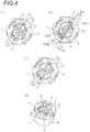
- Fig. 4(c) illustrates the contact state of the contact point when the movable contact point is operated to be rotated to the connection-operation angle of the IG1 terminal and the ST terminal.
- one end of the movable contact point 2 is supported on the power supply terminal 4 and the movable contact point 2 comes into contact with the chamfered portion 8 of the fixed contact point 1. Therefore, in a case where the contact point is worn, the contact point is sequentially moved in the direction of the power supply terminal 4 and a clean contact state is always ensured.
- a rotary switch device that rotates movable contact points 2 on fixed contact points 1 so as to connect and disconnect the fixed contact points 1 and the movable contact points 2.
- the fixed contact points 1 and the movable contact points 2 have contact surfaces which are band shapes and to which corrosion-resistant conductive processing is applied.
- Corrosion of the contact surfaces of the fixed contact points 1 and the movable contact points 2 of the rotary switch device is prevented.
- the contact surfaces are held clean without depending on a cleaning operation by sliding at high contact pressure. Therefore, even if the contact point is used for the low current, corrosion does not occur on the contact surfaces and the occurrence of contact failure due to the occurrence of the insulating film can be prevented.
- both contact points are formed in the elongated band shape and both contact points are moved from one end portion to the other end portion together with the rotation of the movable contact point 2. Therefore, even if damage of the film of the contact position occurs due to arc discharging, a clean surface state is maintained in both contact surfaces in the connection-operation angle. Therefore, the contact failure does not occur.
- a conductive processing surface for corrosion protection can be obtained by applying silver plating or applying clad processing and disc processing on the surface of the conductive member such as copper.
- the same structure may also be used for the high current.
- the transient contact region 3 of the fixed contact points 1 may be formed in a shape in which a moving speed on the movable contact points 2 is a low speed in a vicinity of a contact start point.
- the formation of the transient contact region 3 is able to be realized by moving the strip-like movable contact point 2 on the strip-like fixed contact point 1 that is disposed to be inclined so that the distance of the movable contact point 2 to the rotational center is changed. If the inclination in the vicinity of the contact start point between the fixed contact point 1 and the movable contact point 2 is moderated, the moving speed of the contact point of the movable contact point 2 with the fixed contact point 1 is lowered when the movable contact point 2 is operated to be rotated at a predetermined angular speed.
- the transient contact region 3 of the fixed contact points 1 may be formed in a shape in which a distance between the transient contact region and a rotational center of the movable contact points 2 is the maximum in a vicinity of a contact start position.
- a peripheral speed of the movable contact point 2 on the fixed contact point 1 becomes the maximum in the contact start point in which the distance from the rotational center becomes the maximum. Therefore, a transit time becomes the minimum. As a result, a distance of the fixed electrode influenced by arc discharging becomes the minimum and it is possible to effectively prevent degradation of the electrode.
- the rotary switch device may further include a switch case 5 that exposes the fixed contact points 1 and a power supply terminal 4 toward a line in a predetermined contact direction and holds the fixed contact points 1 and the power supply terminal 4, and a contact point holder 6 that holds the movable contact points rotatably around an axis along the line in the contact direction and reciprocatably toward the line in the contact direction.
- the movable contact points are formed in plate shapes having a predetermined thickness.
- the movable contact points 2 are always in contact with the power supply terminal 4 and are respectively in contact with the fixed contact points 1 during conduction with predetermined contact pressure by compression springs 7.
- the movable contact point 2 has a floating structure in which a biasing force is applied in a contact point pressure applying direction. Therefore, followability is increased with respect to the fixed contact point 1, connection reliability is improved, and then the structure is simplified.
- Chamfered portions 8 may be formed in side edges of the fixed contact points 1.
- the power supply terminal 4 and the fixed contact points 1 may be disposed at different heights in the direction of the line in the contact direction so as to hold the movable contact points 2 in an inclined posture and the movable contact points 2 may be in contact with ridge lines of the chamfered portions 8 of the fixed contact points 1 to be conductive.
- the chamfered portions are formed in the side edges of the fixed contact points 1 and the movable contact points 2 of the floating state come into line contact with the ridge lines of the chamfered portions 8. Therefore, homogeneous contact quality is ensured in each moving point.
- Raised protrusions 10 of the movable contact point 2, of which the contact start points of the fixed contact points 1 are defined as end points, and of which the end points are formed by inclined surfaces 9, may be provided in the switch case 5.
- the movable contact point 2 rides the raised protrusion 10 in a non-contact rotation position and the contact start is performed by causing the entire surface of the contact surface of the movable contact point 2 to gradually come into contact with the fixed contact point 1 while coming down the inclined surface 9 formed in the end point of the raised protrusion 10.
- an end edge of the fixed contact point 1 is the connection start point, discharge concentration occurs due to an edge effect, and damage of the contact point is increased.
- the contact start is performed in a state where the movable contact point 2 lands on the fixed contact point 1. Therefore, it is possible to reduce the damage of the contact point due to the edge effect.
- the buffering recessed portions 11 separating the fixed contact points 1 and the power supply terminal 4 may be provided in the switch case 5.
- the buffering recessed portions 11 provided between the fixed contact points 1 and the power supply terminal 4 are a storage space of particles and the like due to arc discharging and then become buffering bands which prevents deposition of conductive particles between the fixed contact points 1 and the power supply terminal 4 in a continuous shape. Therefore, a continuous conductive particle layer is formed between the fixed contact points 1 and the power supply terminal 4, and short-circuit is prevented between the fixed terminal and the power supply terminal 4.
Landscapes
- Engineering & Computer Science (AREA)
- Mechanical Engineering (AREA)
- Rotary Switch, Piano Key Switch, And Lever Switch (AREA)
Claims (7)
- Dispositif de commutateur rotatif qui fait tourner des points de contact mobiles (2) sur des points de contact fixes (1) afin de connecter et déconnecter les points de contact fixes (1) et les points de contact mobiles (2),
dans lequel les points de contact fixes (1) et les points de contact mobiles (2) ont des surfaces de contact qui ont des formes de bandes et sur lesquelles un traitement conducteur résistant à la corrosion est appliqué, et
dans lequel une région de contact temporaire (3), dans laquelle un point de contact entre un point de contact fixe (1) et un point de contact mobile (2) est déplacé d'une partie d'extrémité à l'autre partie d'extrémité, selon un angle de fonctionnement de connexion prédéterminé définissant l'orientation des points de contact mobiles (2) par rapport aux points de contact fixes (1) à partir du commencement du contact par rapport à l'autre des points de contact fixes (1) et des points de contact mobiles (2), est prévue sur les points de contact fixes (1),
caractérisé en ce que la région de contact temporaire est disposée dans une forme inclinée progressivement vers un centre de rotation d'un support de point de contact. - Dispositif de commutateur rotatif selon la revendication 1,
dans lequel la région de contact temporaire (3) des points de contact fixes (1) est formée dans des formes dans lesquelles une vitesse de déplacement des points de contact par rapport aux points de contact fixes (1) sur les points de contact mobiles est une faible vitesse à proximité d'un point de commencement de contact. - Dispositif de commutateur rotatif selon la revendication 1 ou 2,
dans lequel la région de contact temporaire (3) des points de contact fixes (1) est formée dans des formes dans lesquelles une distance entre un point de la région de contact temporaire (3) et un centre de rotation des points de contact mobiles (2) est au maximum à proximité d'une position de commencement de contact. - Dispositif de commutateur rotatif selon la revendication 1, 2 ou 3, comprenant en outre :un boîtier de commutateur (5) qui expose les points de contact fixes (1) et une borne d'alimentation (4) vers une ligne dans une direction de contact prédéterminée et maintient les points de contact fixes (1) et la borne d'alimentation (4) ; etun support de point de contact (6) qui supporte les points de contact mobiles (2) en rotation autour d'un axe le long de la ligne dans la direction de contact et de manière réciproque vers la ligne dans la direction de contact,dans lequel les points de contact mobiles (2) sont formés en forme de plaque ayant une épaisseur prédéterminée, etdans lequel les points de contact mobiles (2) sont toujours en contact avec la borne d'alimentation (4) et sont respectivement en contact avec les points de contact fixes (1) pendant la conduction avec la pression de contact prédéterminée par des ressorts de compression (7).
- Dispositif de commutateur rotatif selon la revendication 4,
dans lequel des parties chanfreinées (8) sont formées dans des bords latéraux des points de contact fixes (1), et
dans lequel la borne d'alimentation (4) et les points de contact fixes (1) sont disposés à différentes hauteurs dans la direction de la ligne dans la direction de contact afin de maintenir les points de contact mobiles (2) dans une posture inclinée et les points de contact mobiles (2) sont en contact avec les lignes de crête des parties chanfreinées (8) des points de contact fixes (1) pour être conducteurs. - Dispositif de commutateur rotatif selon la revendication 4 ou 5,
dans lequel les saillies relevées (10) des points de contact mobiles (2), dont les points de commencement de contact des points de contact fixes (1) sont définis comme étant des points d'extrémité, et dans les points d'extrémité sont formés par des surfaces inclinées (9), sont prévues dans le boîtier de commutateur (5). - Dispositif de commutateur rotatif selon la revendication 4, 5 ou 6,
dans lequel des parties évidées tampons (1) séparant les points de contact fixes et la borne d'alimentation (4) sont prévues dans le boîtier de commutateur (5).
Applications Claiming Priority (2)
| Application Number | Priority Date | Filing Date | Title |
|---|---|---|---|
| JP2014091444A JP6322470B2 (ja) | 2014-04-25 | 2014-04-25 | ロータリースイッチ装置 |
| PCT/JP2015/062451 WO2015163430A1 (fr) | 2014-04-25 | 2015-04-23 | Dispositif de commutateur rotatif |
Publications (3)
| Publication Number | Publication Date |
|---|---|
| EP3136412A1 EP3136412A1 (fr) | 2017-03-01 |
| EP3136412A4 EP3136412A4 (fr) | 2018-01-03 |
| EP3136412B1 true EP3136412B1 (fr) | 2019-06-26 |
Family
ID=54332592
Family Applications (1)
| Application Number | Title | Priority Date | Filing Date |
|---|---|---|---|
| EP15783381.5A Active EP3136412B1 (fr) | 2014-04-25 | 2015-04-23 | Dispositif de commutateur rotatif |
Country Status (8)
| Country | Link |
|---|---|
| US (1) | US9972452B2 (fr) |
| EP (1) | EP3136412B1 (fr) |
| JP (1) | JP6322470B2 (fr) |
| KR (1) | KR20160147757A (fr) |
| CN (1) | CN106256010B (fr) |
| AU (1) | AU2015251033A1 (fr) |
| RU (1) | RU2016146112A (fr) |
| WO (1) | WO2015163430A1 (fr) |
Families Citing this family (6)
| Publication number | Priority date | Publication date | Assignee | Title |
|---|---|---|---|---|
| DE102015111832A1 (de) * | 2015-07-21 | 2017-01-26 | Huf Hülsbeck & Fürst Gmbh & Co. Kg | Kraftfahrzeug-Lenkschloss |
| JP6655470B2 (ja) * | 2016-05-17 | 2020-02-26 | 株式会社アルファ | ロータリースイッチ装置 |
| JP6774219B2 (ja) * | 2016-05-17 | 2020-10-21 | 株式会社アルファ | ロータリースイッチ装置 |
| KR101760332B1 (ko) * | 2016-10-14 | 2017-07-21 | 주식회사 대륙 | 전기 회전스위치 장치 |
| EP3653824B1 (fr) * | 2018-11-15 | 2024-09-04 | Inalfa Roof Systems Group B.V. | Dispositif permettant de détecter une force d'impact et son procédé de fabrication |
| KR102845125B1 (ko) | 2019-12-03 | 2025-08-13 | 현대자동차주식회사 | 스위치 |
Family Cites Families (10)
| Publication number | Priority date | Publication date | Assignee | Title |
|---|---|---|---|---|
| US2195307A (en) * | 1939-03-09 | 1940-03-26 | Mallory & Co Inc P R | Contact |
| JPS6489222A (en) * | 1987-09-30 | 1989-04-03 | Matsushita Electric Industrial Co Ltd | Switch |
| JPH07245040A (ja) * | 1994-03-01 | 1995-09-19 | Kansei Corp | 回転式スイッチ |
| JPH09147673A (ja) * | 1995-11-17 | 1997-06-06 | Tokai Rika Co Ltd | スライドスイッチ |
| JPH10125178A (ja) * | 1996-10-18 | 1998-05-15 | Aisin Aw Co Ltd | 位置検出スイッチ |
| JPH11176271A (ja) * | 1997-12-15 | 1999-07-02 | Yuhshin Co Ltd | スイッチの接点 |
| JP3561404B2 (ja) * | 1998-02-24 | 2004-09-02 | 株式会社ホンダロック | ロータリースイッチ装置 |
| US6114638A (en) | 1998-02-24 | 2000-09-05 | Kabushiki Kaisha Honda Lock | Rotary switch device |
| JPH11260193A (ja) * | 1998-03-11 | 1999-09-24 | Yuhshin Co Ltd | 切り替えスイッチ |
| JP2003242858A (ja) * | 2002-02-14 | 2003-08-29 | Asahi Matsushita Electric Works Ltd | ロータリースイッチ |
-
2014
- 2014-04-25 JP JP2014091444A patent/JP6322470B2/ja active Active
-
2015
- 2015-04-23 CN CN201580022091.1A patent/CN106256010B/zh active Active
- 2015-04-23 AU AU2015251033A patent/AU2015251033A1/en not_active Abandoned
- 2015-04-23 WO PCT/JP2015/062451 patent/WO2015163430A1/fr not_active Ceased
- 2015-04-23 EP EP15783381.5A patent/EP3136412B1/fr active Active
- 2015-04-23 KR KR1020167029542A patent/KR20160147757A/ko not_active Withdrawn
- 2015-04-23 RU RU2016146112A patent/RU2016146112A/ru not_active Application Discontinuation
-
2016
- 2016-10-24 US US15/332,002 patent/US9972452B2/en active Active
Non-Patent Citations (1)
| Title |
|---|
| None * |
Also Published As
| Publication number | Publication date |
|---|---|
| RU2016146112A (ru) | 2018-05-28 |
| JP2015210933A (ja) | 2015-11-24 |
| EP3136412A4 (fr) | 2018-01-03 |
| JP6322470B2 (ja) | 2018-05-09 |
| CN106256010B (zh) | 2019-11-08 |
| AU2015251033A1 (en) | 2016-11-10 |
| CN106256010A (zh) | 2016-12-21 |
| US9972452B2 (en) | 2018-05-15 |
| EP3136412A1 (fr) | 2017-03-01 |
| WO2015163430A1 (fr) | 2015-10-29 |
| KR20160147757A (ko) | 2016-12-23 |
| US20170040125A1 (en) | 2017-02-09 |
Similar Documents
| Publication | Publication Date | Title |
|---|---|---|
| EP3136412B1 (fr) | Dispositif de commutateur rotatif | |
| US8075328B2 (en) | Connector with an actuator pushed by a base-plate | |
| US4336974A (en) | Coaxial rotary joint | |
| EP3460820B1 (fr) | Dispositif de commutateur rotatif | |
| WO2014055227A1 (fr) | Ensemble de contact électrique | |
| CN104067363A (zh) | 具有摩擦触点的电开关 | |
| US10650990B2 (en) | Rotary switch | |
| CN202585217U (zh) | 旋转型电子部件 | |
| EP3460819B1 (fr) | Dispositif commutateur rotatif | |
| JP6655470B2 (ja) | ロータリースイッチ装置 | |
| US20160217948A1 (en) | Pivoting electrical switch | |
| WO2016036396A1 (fr) | Commutateur électrique pivotant | |
| JP2019179666A (ja) | 端子対 | |
| JP2008262793A (ja) | スプリングピン、及びバッテリコネクタ装置 | |
| JP4946577B2 (ja) | 回転プラグを備えた機器 | |
| JP2011171239A (ja) | 開閉器 | |
| JP2008258061A (ja) | ロータリスイッチ |
Legal Events
| Date | Code | Title | Description |
|---|---|---|---|
| STAA | Information on the status of an ep patent application or granted ep patent |
Free format text: STATUS: THE INTERNATIONAL PUBLICATION HAS BEEN MADE |
|
| PUAI | Public reference made under article 153(3) epc to a published international application that has entered the european phase |
Free format text: ORIGINAL CODE: 0009012 |
|
| STAA | Information on the status of an ep patent application or granted ep patent |
Free format text: STATUS: REQUEST FOR EXAMINATION WAS MADE |
|
| 17P | Request for examination filed |
Effective date: 20161025 |
|
| AK | Designated contracting states |
Kind code of ref document: A1 Designated state(s): AL AT BE BG CH CY CZ DE DK EE ES FI FR GB GR HR HU IE IS IT LI LT LU LV MC MK MT NL NO PL PT RO RS SE SI SK SM TR |
|
| AX | Request for extension of the european patent |
Extension state: BA ME |
|
| DAV | Request for validation of the european patent (deleted) | ||
| DAX | Request for extension of the european patent (deleted) | ||
| A4 | Supplementary search report drawn up and despatched |
Effective date: 20171201 |
|
| RIC1 | Information provided on ipc code assigned before grant |
Ipc: H01H 19/02 20060101AFI20171128BHEP Ipc: H01H 19/58 20060101ALI20171128BHEP Ipc: B60R 16/02 20060101ALI20171128BHEP Ipc: H01H 1/06 20060101ALI20171128BHEP Ipc: B60R 25/021 20130101ALI20171128BHEP Ipc: H01H 1/36 20060101ALI20171128BHEP Ipc: H01H 19/08 20060101ALI20171128BHEP |
|
| GRAP | Despatch of communication of intention to grant a patent |
Free format text: ORIGINAL CODE: EPIDOSNIGR1 |
|
| STAA | Information on the status of an ep patent application or granted ep patent |
Free format text: STATUS: GRANT OF PATENT IS INTENDED |
|
| INTG | Intention to grant announced |
Effective date: 20190215 |
|
| GRAS | Grant fee paid |
Free format text: ORIGINAL CODE: EPIDOSNIGR3 |
|
| GRAA | (expected) grant |
Free format text: ORIGINAL CODE: 0009210 |
|
| STAA | Information on the status of an ep patent application or granted ep patent |
Free format text: STATUS: THE PATENT HAS BEEN GRANTED |
|
| AK | Designated contracting states |
Kind code of ref document: B1 Designated state(s): AL AT BE BG CH CY CZ DE DK EE ES FI FR GB GR HR HU IE IS IT LI LT LU LV MC MK MT NL NO PL PT RO RS SE SI SK SM TR |
|
| REG | Reference to a national code |
Ref country code: GB Ref legal event code: FG4D |
|
| REG | Reference to a national code |
Ref country code: CH Ref legal event code: EP |
|
| REG | Reference to a national code |
Ref country code: DE Ref legal event code: R096 Ref document number: 602015032784 Country of ref document: DE |
|
| REG | Reference to a national code |
Ref country code: AT Ref legal event code: REF Ref document number: 1149267 Country of ref document: AT Kind code of ref document: T Effective date: 20190715 |
|
| REG | Reference to a national code |
Ref country code: IE Ref legal event code: FG4D |
|
| REG | Reference to a national code |
Ref country code: NL Ref legal event code: MP Effective date: 20190626 |
|
| PG25 | Lapsed in a contracting state [announced via postgrant information from national office to epo] |
Ref country code: FI Free format text: LAPSE BECAUSE OF FAILURE TO SUBMIT A TRANSLATION OF THE DESCRIPTION OR TO PAY THE FEE WITHIN THE PRESCRIBED TIME-LIMIT Effective date: 20190626 Ref country code: NO Free format text: LAPSE BECAUSE OF FAILURE TO SUBMIT A TRANSLATION OF THE DESCRIPTION OR TO PAY THE FEE WITHIN THE PRESCRIBED TIME-LIMIT Effective date: 20190926 Ref country code: LT Free format text: LAPSE BECAUSE OF FAILURE TO SUBMIT A TRANSLATION OF THE DESCRIPTION OR TO PAY THE FEE WITHIN THE PRESCRIBED TIME-LIMIT Effective date: 20190626 Ref country code: AL Free format text: LAPSE BECAUSE OF FAILURE TO SUBMIT A TRANSLATION OF THE DESCRIPTION OR TO PAY THE FEE WITHIN THE PRESCRIBED TIME-LIMIT Effective date: 20190626 Ref country code: HR Free format text: LAPSE BECAUSE OF FAILURE TO SUBMIT A TRANSLATION OF THE DESCRIPTION OR TO PAY THE FEE WITHIN THE PRESCRIBED TIME-LIMIT Effective date: 20190626 Ref country code: SE Free format text: LAPSE BECAUSE OF FAILURE TO SUBMIT A TRANSLATION OF THE DESCRIPTION OR TO PAY THE FEE WITHIN THE PRESCRIBED TIME-LIMIT Effective date: 20190626 |
|
| REG | Reference to a national code |
Ref country code: LT Ref legal event code: MG4D |
|
| PG25 | Lapsed in a contracting state [announced via postgrant information from national office to epo] |
Ref country code: GR Free format text: LAPSE BECAUSE OF FAILURE TO SUBMIT A TRANSLATION OF THE DESCRIPTION OR TO PAY THE FEE WITHIN THE PRESCRIBED TIME-LIMIT Effective date: 20190927 Ref country code: LV Free format text: LAPSE BECAUSE OF FAILURE TO SUBMIT A TRANSLATION OF THE DESCRIPTION OR TO PAY THE FEE WITHIN THE PRESCRIBED TIME-LIMIT Effective date: 20190626 Ref country code: BG Free format text: LAPSE BECAUSE OF FAILURE TO SUBMIT A TRANSLATION OF THE DESCRIPTION OR TO PAY THE FEE WITHIN THE PRESCRIBED TIME-LIMIT Effective date: 20190926 Ref country code: RS Free format text: LAPSE BECAUSE OF FAILURE TO SUBMIT A TRANSLATION OF THE DESCRIPTION OR TO PAY THE FEE WITHIN THE PRESCRIBED TIME-LIMIT Effective date: 20190626 |
|
| REG | Reference to a national code |
Ref country code: AT Ref legal event code: MK05 Ref document number: 1149267 Country of ref document: AT Kind code of ref document: T Effective date: 20190626 |
|
| PG25 | Lapsed in a contracting state [announced via postgrant information from national office to epo] |
Ref country code: RO Free format text: LAPSE BECAUSE OF FAILURE TO SUBMIT A TRANSLATION OF THE DESCRIPTION OR TO PAY THE FEE WITHIN THE PRESCRIBED TIME-LIMIT Effective date: 20190626 Ref country code: SK Free format text: LAPSE BECAUSE OF FAILURE TO SUBMIT A TRANSLATION OF THE DESCRIPTION OR TO PAY THE FEE WITHIN THE PRESCRIBED TIME-LIMIT Effective date: 20190626 Ref country code: NL Free format text: LAPSE BECAUSE OF FAILURE TO SUBMIT A TRANSLATION OF THE DESCRIPTION OR TO PAY THE FEE WITHIN THE PRESCRIBED TIME-LIMIT Effective date: 20190626 Ref country code: CZ Free format text: LAPSE BECAUSE OF FAILURE TO SUBMIT A TRANSLATION OF THE DESCRIPTION OR TO PAY THE FEE WITHIN THE PRESCRIBED TIME-LIMIT Effective date: 20190626 Ref country code: PT Free format text: LAPSE BECAUSE OF FAILURE TO SUBMIT A TRANSLATION OF THE DESCRIPTION OR TO PAY THE FEE WITHIN THE PRESCRIBED TIME-LIMIT Effective date: 20191028 Ref country code: AT Free format text: LAPSE BECAUSE OF FAILURE TO SUBMIT A TRANSLATION OF THE DESCRIPTION OR TO PAY THE FEE WITHIN THE PRESCRIBED TIME-LIMIT Effective date: 20190626 Ref country code: EE Free format text: LAPSE BECAUSE OF FAILURE TO SUBMIT A TRANSLATION OF THE DESCRIPTION OR TO PAY THE FEE WITHIN THE PRESCRIBED TIME-LIMIT Effective date: 20190626 |
|
| PG25 | Lapsed in a contracting state [announced via postgrant information from national office to epo] |
Ref country code: IT Free format text: LAPSE BECAUSE OF FAILURE TO SUBMIT A TRANSLATION OF THE DESCRIPTION OR TO PAY THE FEE WITHIN THE PRESCRIBED TIME-LIMIT Effective date: 20190626 Ref country code: SM Free format text: LAPSE BECAUSE OF FAILURE TO SUBMIT A TRANSLATION OF THE DESCRIPTION OR TO PAY THE FEE WITHIN THE PRESCRIBED TIME-LIMIT Effective date: 20190626 Ref country code: IS Free format text: LAPSE BECAUSE OF FAILURE TO SUBMIT A TRANSLATION OF THE DESCRIPTION OR TO PAY THE FEE WITHIN THE PRESCRIBED TIME-LIMIT Effective date: 20191026 Ref country code: ES Free format text: LAPSE BECAUSE OF FAILURE TO SUBMIT A TRANSLATION OF THE DESCRIPTION OR TO PAY THE FEE WITHIN THE PRESCRIBED TIME-LIMIT Effective date: 20190626 |
|
| PG25 | Lapsed in a contracting state [announced via postgrant information from national office to epo] |
Ref country code: TR Free format text: LAPSE BECAUSE OF FAILURE TO SUBMIT A TRANSLATION OF THE DESCRIPTION OR TO PAY THE FEE WITHIN THE PRESCRIBED TIME-LIMIT Effective date: 20190626 |
|
| PG25 | Lapsed in a contracting state [announced via postgrant information from national office to epo] |
Ref country code: PL Free format text: LAPSE BECAUSE OF FAILURE TO SUBMIT A TRANSLATION OF THE DESCRIPTION OR TO PAY THE FEE WITHIN THE PRESCRIBED TIME-LIMIT Effective date: 20190626 Ref country code: DK Free format text: LAPSE BECAUSE OF FAILURE TO SUBMIT A TRANSLATION OF THE DESCRIPTION OR TO PAY THE FEE WITHIN THE PRESCRIBED TIME-LIMIT Effective date: 20190626 |
|
| PG25 | Lapsed in a contracting state [announced via postgrant information from national office to epo] |
Ref country code: IS Free format text: LAPSE BECAUSE OF FAILURE TO SUBMIT A TRANSLATION OF THE DESCRIPTION OR TO PAY THE FEE WITHIN THE PRESCRIBED TIME-LIMIT Effective date: 20200224 |
|
| REG | Reference to a national code |
Ref country code: DE Ref legal event code: R097 Ref document number: 602015032784 Country of ref document: DE |
|
| PLBE | No opposition filed within time limit |
Free format text: ORIGINAL CODE: 0009261 |
|
| STAA | Information on the status of an ep patent application or granted ep patent |
Free format text: STATUS: NO OPPOSITION FILED WITHIN TIME LIMIT |
|
| PG2D | Information on lapse in contracting state deleted |
Ref country code: IS |
|
| 26N | No opposition filed |
Effective date: 20200603 |
|
| PG25 | Lapsed in a contracting state [announced via postgrant information from national office to epo] |
Ref country code: SI Free format text: LAPSE BECAUSE OF FAILURE TO SUBMIT A TRANSLATION OF THE DESCRIPTION OR TO PAY THE FEE WITHIN THE PRESCRIBED TIME-LIMIT Effective date: 20190626 |
|
| PG25 | Lapsed in a contracting state [announced via postgrant information from national office to epo] |
Ref country code: MC Free format text: LAPSE BECAUSE OF FAILURE TO SUBMIT A TRANSLATION OF THE DESCRIPTION OR TO PAY THE FEE WITHIN THE PRESCRIBED TIME-LIMIT Effective date: 20190626 |
|
| REG | Reference to a national code |
Ref country code: CH Ref legal event code: PL |
|
| PG25 | Lapsed in a contracting state [announced via postgrant information from national office to epo] |
Ref country code: LU Free format text: LAPSE BECAUSE OF NON-PAYMENT OF DUE FEES Effective date: 20200423 Ref country code: LI Free format text: LAPSE BECAUSE OF NON-PAYMENT OF DUE FEES Effective date: 20200430 Ref country code: CH Free format text: LAPSE BECAUSE OF NON-PAYMENT OF DUE FEES Effective date: 20200430 |
|
| REG | Reference to a national code |
Ref country code: BE Ref legal event code: MM Effective date: 20200430 |
|
| PG25 | Lapsed in a contracting state [announced via postgrant information from national office to epo] |
Ref country code: BE Free format text: LAPSE BECAUSE OF NON-PAYMENT OF DUE FEES Effective date: 20200430 |
|
| PG25 | Lapsed in a contracting state [announced via postgrant information from national office to epo] |
Ref country code: IE Free format text: LAPSE BECAUSE OF NON-PAYMENT OF DUE FEES Effective date: 20200423 |
|
| PGFP | Annual fee paid to national office [announced via postgrant information from national office to epo] |
Ref country code: FR Payment date: 20210309 Year of fee payment: 7 |
|
| PGFP | Annual fee paid to national office [announced via postgrant information from national office to epo] |
Ref country code: GB Payment date: 20210331 Year of fee payment: 7 |
|
| PG25 | Lapsed in a contracting state [announced via postgrant information from national office to epo] |
Ref country code: MT Free format text: LAPSE BECAUSE OF FAILURE TO SUBMIT A TRANSLATION OF THE DESCRIPTION OR TO PAY THE FEE WITHIN THE PRESCRIBED TIME-LIMIT Effective date: 20190626 Ref country code: CY Free format text: LAPSE BECAUSE OF FAILURE TO SUBMIT A TRANSLATION OF THE DESCRIPTION OR TO PAY THE FEE WITHIN THE PRESCRIBED TIME-LIMIT Effective date: 20190626 |
|
| PG25 | Lapsed in a contracting state [announced via postgrant information from national office to epo] |
Ref country code: MK Free format text: LAPSE BECAUSE OF FAILURE TO SUBMIT A TRANSLATION OF THE DESCRIPTION OR TO PAY THE FEE WITHIN THE PRESCRIBED TIME-LIMIT Effective date: 20190626 |
|
| GBPC | Gb: european patent ceased through non-payment of renewal fee |
Effective date: 20220423 |
|
| PG25 | Lapsed in a contracting state [announced via postgrant information from national office to epo] |
Ref country code: GB Free format text: LAPSE BECAUSE OF NON-PAYMENT OF DUE FEES Effective date: 20220423 Ref country code: FR Free format text: LAPSE BECAUSE OF NON-PAYMENT OF DUE FEES Effective date: 20220430 |
|
| PGFP | Annual fee paid to national office [announced via postgrant information from national office to epo] |
Ref country code: DE Payment date: 20250305 Year of fee payment: 11 |