EP3136500A1 - Verfahren, vorrichtung und system zur erfassung von technischen antennenparametern - Google Patents
Verfahren, vorrichtung und system zur erfassung von technischen antennenparametern Download PDFInfo
- Publication number
- EP3136500A1 EP3136500A1 EP14893419.3A EP14893419A EP3136500A1 EP 3136500 A1 EP3136500 A1 EP 3136500A1 EP 14893419 A EP14893419 A EP 14893419A EP 3136500 A1 EP3136500 A1 EP 3136500A1
- Authority
- EP
- European Patent Office
- Prior art keywords
- antenna
- coordinate system
- plane
- mapping
- spatial coordinate
- Prior art date
- Legal status (The legal status is an assumption and is not a legal conclusion. Google has not performed a legal analysis and makes no representation as to the accuracy of the status listed.)
- Withdrawn
Links
Images





Classifications
-
- H—ELECTRICITY
- H01—ELECTRIC ELEMENTS
- H01Q—ANTENNAS, i.e. RADIO AERIALS
- H01Q1/00—Details of, or arrangements associated with, antennas
- H01Q1/12—Supports; Mounting means
- H01Q1/125—Means for positioning
-
- H—ELECTRICITY
- H01—ELECTRIC ELEMENTS
- H01Q—ANTENNAS, i.e. RADIO AERIALS
- H01Q1/00—Details of, or arrangements associated with, antennas
-
- G—PHYSICS
- G01—MEASURING; TESTING
- G01B—MEASURING LENGTH, THICKNESS OR SIMILAR LINEAR DIMENSIONS; MEASURING ANGLES; MEASURING AREAS; MEASURING IRREGULARITIES OF SURFACES OR CONTOURS
- G01B11/00—Measuring arrangements characterised by the use of optical techniques
- G01B11/26—Measuring arrangements characterised by the use of optical techniques for measuring angles or tapers; for testing the alignment of axes
-
- G—PHYSICS
- G06—COMPUTING OR CALCULATING; COUNTING
- G06T—IMAGE DATA PROCESSING OR GENERATION, IN GENERAL
- G06T7/00—Image analysis
- G06T7/60—Analysis of geometric attributes
-
- G—PHYSICS
- G06—COMPUTING OR CALCULATING; COUNTING
- G06T—IMAGE DATA PROCESSING OR GENERATION, IN GENERAL
- G06T7/00—Image analysis
- G06T7/70—Determining position or orientation of objects or cameras
- G06T7/73—Determining position or orientation of objects or cameras using feature-based methods
-
- H—ELECTRICITY
- H04—ELECTRIC COMMUNICATION TECHNIQUE
- H04B—TRANSMISSION
- H04B17/00—Monitoring; Testing
- H04B17/10—Monitoring; Testing of transmitters
- H04B17/101—Monitoring; Testing of transmitters for measurement of specific parameters of the transmitter or components thereof
- H04B17/102—Power radiated at antenna
-
- H—ELECTRICITY
- H04—ELECTRIC COMMUNICATION TECHNIQUE
- H04B—TRANSMISSION
- H04B17/00—Monitoring; Testing
- H04B17/10—Monitoring; Testing of transmitters
- H04B17/101—Monitoring; Testing of transmitters for measurement of specific parameters of the transmitter or components thereof
Definitions
- the present invention relates to the field of communications technologies, and in particular, to a method and device for obtaining an antenna engineering parameter and a related system.
- An antenna is an important component in a wireless communications device.
- Main parameters of the antenna include: an antenna azimuth, an antenna downtilt, and the like. Facts prove that accuracy of these main parameters of the antenna directly affects reception and transmission performance of the wireless communications device. For example, during network construction, parameters such as an antenna azimuth and an antenna downtilt that are designed in advance need to be used to install an antenna. During network optimization, an antenna azimuth, an antenna downtilt, and the like may also need to be adjusted and optimized.
- antenna azimuth, the antenna downtilt, and the like that are designed in advance may fail to be applied correctly.
- an azimuth, a downtilt, and the like may be different from the antenna azimuth, the antenna downtilt, and the like that are designed in advance. Therefore, an azimuth and a downtilt during actual installation of an antenna (actual parameters of the antenna such as the azimuth and the downtilt during actual installation of the antenna may be referred to as antenna engineering parameters) need to be measured sometimes.
- the measured antenna engineering parameters may be compared with designed antenna engineering parameters, to perform particular adjustments to an antenna azimuth, an antenna downtilt, and the like, thereby further improving reception and transmission performance of a signal.
- An existing method for obtaining an antenna engineering parameter mainly relies on on-site manual measurement, and installation personnel measure an antenna azimuth in an outdoor field by using a compass, measure an antenna downtilt in an outdoor field by using a protractor, and record data obtained through measurement.
- the inventors of the present invention find that the prior art has at least the following problems: Factors such as a skill level of an engineer, meticulousness of an engineer, measurement difficulty in an on-site condition, and a level of surrounding electromagnetic interference may all significantly affect measurement precision of an actual azimuth and downtilt of an antenna. When obtained antenna engineering parameters are inaccurate, a case such as an error in a result of radio frequency optimization of a wireless network or an error in configuration of a switching parameter may occur, which may further cause a severe result such as a mass connection loss.
- Embodiments of the present invention provide a method and device for obtaining an antenna engineering parameter and a system, so as to improve precision of an obtained antenna engineering parameter, thereby providing a basis for improvement of reception and transmission performance of a signal.
- a method for measuring an antenna engineering parameter may include:
- the normal direction of the second plane is parallel to a direction obtained by mapping a pointing direction of the antenna into the first three-dimensional spatial coordinate system, or a fourth included angle greater than 0 degree exists between the normal direction of the second plane and a direction obtained by mapping a pointing direction of the antenna into the first three-dimensional spatial coordinate system.
- the obtaining a first image that is obtained by photographing an antenna at a first position includes: obtaining the first image that is obtained by a camera by photographing the antenna at the first position; and the mapping the M characteristic points into a first three-dimensional spatial coordinate system includes: mapping the M characteristic points into the first three-dimensional spatial coordinate system according to an internal parameter and an external parameter of the camera, where the first image is a digital photograph; the external parameter of the camera is (R, T); the internal parameter of the camera is (fx, fy, u0, v0); and a mapping relationship between pixel coordinates ( u p , v p ) of any characteristic point of the M characteristic points included in the first image and coordinates ( x w , y w , z w ) of a three-dimensional space point obtained by mapping the characteristic point into the first three-dimensional spatial coordinate system is as follows: u p , v p ) of any characteristic point of the M characteristic points included in the first image and coordinates ( x
- the obtaining a first image that is obtained by photographing an antenna at a first position includes: obtaining the first image that is obtained by a camera by photographing the antenna at the first position; and the mapping the M characteristic points included in the first image into the first three-dimensional spatial coordinate system includes: mapping the M characteristic points included in the first image into the first three-dimensional spatial coordinate system according to an internal parameter and an external parameter of the camera and a uniform scaling parameter z from a photosensitive component of the camera to the first image.
- the first image is a film photograph;
- the external parameter of the camera is (R, T);
- the internal parameter of the camera is (fx, fy, u0, v0);
- the method further includes:
- the method further includes:
- an apparatus for measuring an antenna engineering parameter may include:
- the normal direction of the second plane is parallel to a direction obtained by mapping a pointing direction of the antenna into the first three-dimensional spatial coordinate system, or a fourth included angle greater than 0 degree exists between the normal direction of the second plane and a direction obtained by mapping a pointing direction of the antenna into the first three-dimensional spatial coordinate system.
- the obtaining unit is specifically configured to obtain the first image that is obtained by a camera by photographing the antenna at the first position; and the mapping unit is specifically configured to map the M characteristic points included in the first image into the first three-dimensional spatial coordinate system according to an internal parameter and an external parameter of the camera and a uniform scaling parameter z from a photosensitive component of the camera to the first image.
- the obtaining unit is specifically configured to obtain the first image that is obtained by the camera by photographing the antenna at the first position;
- the mapping unit is specifically configured to map the M characteristic points included in the first image into the first three-dimensional spatial coordinate system according to the internal parameter and the external parameter of the camera, where the first image is a film photograph;
- the external parameter of the camera is (R, T);
- the internal parameter of the camera is (fx, fy, u0, v0);
- the obtaining unit is further configured to obtain a second image that is obtained by photographing the antenna at a second position, where the second image includes at least N characteristic points on the antenna, the N characteristic points are characteristic points on a surface of the antenna, the N characteristic points are in a same plane but are not on a same straight line, and N is a positive integer greater than 2; and the mapping unit is further configured to map the N characteristic points included in the second image into a second three-dimensional spatial coordinate system, to obtain N three-dimensional space points that are in the second three-dimensional spatial coordinate system and that have a mapping relationship with the N characteristic points, where a second mapping photographing direction is parallel to a direction of an axis in the second three-dimensional spatial coordinate system, or an included angle having a specified angle exists between a second mapping photographing direction
- the obtaining unit is further configured to obtain a second image that is obtained by photographing the antenna at a second position, where the second image includes at least N characteristic points on the antenna, the N characteristic points are characteristic points on a surface of the antenna, the N characteristic points are in a same plane but are not on a same straight line, and N is a positive integer greater than 2; and the mapping unit is further configured to map the N characteristic points included in the second image into a second three-dimensional spatial coordinate system, to obtain N three-dimensional space points that are in the second three-dimensional spatial coordinate system and that have a mapping relationship with the N characteristic points, where a second mapping photographing direction is parallel to a direction of an axis in the second three-dimensional spatial coordinate system, or an included angle having a specified angle exists between a second mapping photographing direction
- a third aspect of the embodiments of the present invention further provides a computer storage medium, where the computer storage medium stores a program, and when the program is executed, some or all of the steps of the method for obtaining an antenna engineering parameter in the foregoing method embodiment are included.
- a first image that is obtained by photographing an antenna at a first position is obtained, where the first image includes at least M characteristic points on the antenna, the M characteristic points are characteristic points on a surface of the antenna, the M characteristic points are in a same plane but are not on a same straight line, and M is a positive integer greater than 2; the M characteristic points included in the first image are mapped into a first three-dimensional spatial coordinate system, to obtain M three-dimensional space points that are in the first three-dimensional spatial coordinate system and that have a mapping relationship with the M characteristic points.
- a mapping relationship between a practical scenario and a mathematical model is established, and a photographing direction of photographing the first image by a camera is parallel to the direction of an axis in the first three-dimensional spatial coordinate system.
- a downtilt of the antenna is obtained according to a first angle and/or an azimuth of the antenna is obtained according to a second angle, where the second angle is equal to an included angle between a first reference direction in a first plane and a projection of a normal direction of a second plane on the first plane, and the first angle is equal to an included angle between the normal direction of the second plane and the first plane.
- a photograph of a practical scenario is used to establish a mapping relationship between a practical scenario and a mathematical model, so as to to calculate an engineering parameter of an antenna by using such a mathematical model.
- the solutions provided in the embodiments of the present invention help to improve precision of an obtained antenna engineering parameter, thereby providing a basis for improvement of reception and transmission performance of a signal.
- a solution also helps to greatly reduce difficulty of measuring an antenna engineering parameter.
- Embodiments of the present invention provide a method and device for obtaining an antenna engineering parameter and a system, so as to improve precision of an obtained antenna engineering parameter, thereby providing a basis for improvement of reception and transmission performance of a signal.
- the method for measuring an antenna engineering parameter may include: obtaining, by a measurement device, a first image that is obtained by photographing an antenna at a first position, where the first image includes at least M characteristic points on the antenna, the M characteristic points are characteristic points on a surface of the antenna, the M characteristic points are in a same plane but are not on a same straight line, and M is a positive integer greater than 2; mapping, by the measurement device, the M characteristic points included in the first image into a first three-dimensional spatial coordinate system, to obtain M three-dimensional space points that are in the first three-dimensional spatial coordinate system and that have a mapping relationship with the M characteristic points, where a first mapping photographing direction may be parallel to the direction of an axis in the first three-dimensional spatial coordinate system, or an included angle having a specified angle exists between a first mapping photographing direction and the direction of an axis in the first three-dimensional spatial coordinate system, and the first mapping photographing direction is obtained by mapping a photographing
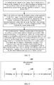
- FIG. 1 is a schematic flowchart of a method for measuring an antenna engineering parameter according to an embodiment of the present invention.
- the method for measuring an antenna engineering parameter according to this embodiment of the present invention may include the following content:
- the first image includes at least M characteristic points on the antenna, the M characteristic points are characteristic points on a surface of the antenna, the M characteristic points are in a same plane but are not on a same straight line, where M is a positive integer greater than 2.
- the antenna may include k characteristic points, and the M characteristic points may be some or all of the characteristic points of the k characteristic points.
- a position relationship between a plane defined by these characteristic points and a pointing direction of the antenna may be determined.
- the position relationship between the plane defined by these characteristic points and the pointing direction of the antenna may be a parallel relationship, a perpendicular relationship or a relationship of another specific angle.
- a first mapping photographing direction may be parallel to the direction of an axis in the first three-dimensional spatial coordinate system, or an included angle having a specified angle exists between a first mapping photographing direction and the direction of an axis in the first three-dimensional spatial coordinate system, and the first mapping photographing direction is obtained by mapping a photographing direction of photographing the first image into the first three-dimensional spatial coordinate system.
- an example in which the first mapping photographing direction is parallel to the direction of an axis (for example, a y axis) in the first three-dimensional spatial coordinate system is mainly used.
- the obtaining a first image that is obtained by photographing an antenna at a first position may include obtaining the first image that is obtained by a camera by photographing the antenna at the first position.
- the camera may be a component in the measurement device, or may be a component outside the measurement device.
- the measurement device is a portable terminal device (such as a tablet or a mobile phone), and the camera is a component in the portable terminal device.
- the measurement device may also be a personal computer, a server, or the like, and the camera is a component of the portable terminal device.
- the portable terminal obtains the first image that is obtained by the camera by photographing the antenna at the first position, and sends, to the measurement device, the first image that is obtained by the camera by photographing the antenna at the first position, so that the measurement device accordingly obtains the first image that is obtained by the camera by photographing the antenna at the first position.
- the mapping the M characteristic points included in the first image into the first three-dimensional spatial coordinate system may include: mapping the M characteristic points included in the first image into the first three-dimensional spatial coordinate system according to an internal parameter and an external parameter of the camera, to obtain M three-dimensional space points that are in the first three-dimensional spatial coordinate system and that have a mapping relationship with the M characteristic points.
- 103 Obtain a downtilt of the antenna according to a first angle and/or obtain an azimuth of the antenna according to a second angle.
- the second angle is equal to an included angle between a first reference direction in a first plane and a projection of a normal direction of a second plane on the first plane
- the first angle is equal to an included angle between the normal direction of the second plane and the first plane
- the first plane is obtained by mapping a first reference plane into the first three-dimensional spatial coordinate system
- the second plane is determined by the M three-dimensional space points
- the first reference direction is obtained by mapping a first azimuth reference direction into the first three-dimensional spatial coordinate system.
- the first azimuth reference direction may be, for example, a due north direction or a due south direction, or a first included angle greater than 0 degree exists between the first azimuth reference direction and a due north direction (that is, the first azimuth reference direction can be determined according to the due north direction and the first included angle), or a second included angle greater than 0 degree exists between the first azimuth reference direction and a due south direction (that is, the first azimuth reference direction can be determined according to the due south direction and the second included angle).
- the first reference plane may be a horizontal plane, or a third included angle greater than 0 degree exists between the first reference plane and a horizontal plane (that is, the first reference plane can be determined according to the horizontal plane and the third included angle).
- the first reference plane may also be a vertical plane, or a seventh included angle greater than 0 degree exists between the first reference plane and a vertical plane (that is, the first reference plane can be determined according to the vertical plane and the seventh included angle).
- the terminal device may determine a due north direction or a due south direction by using a magnetic flux sensor, a compass, or the like in the terminal device.
- the terminal device may also obtain a gravity direction by using a gravity sensor, and a vertical plane of the gravity direction is the horizontal plane.
- a gravity direction, a due north direction, or the like may be determined by using some reference objects in the photographed image.
- an antenna pole is usually perpendicular to a ground surface. Therefore, a vertical plane may be determined according to a pointing direction of an antenna pole. When the vertical plane is determined, the horizontal plane is determined.
- the horizontal plane may be mapped into a three-dimensional coordinate system and used as a reference plane.
- the first reference plane in step 103 may be the horizontal plane, and the first plane may be obtained by mapping the horizontal plane into the first three-dimensional spatial coordinate system. It may be understood that, a scenario in which a reference direction or a reference plane is determined by using another reference object may be similar thereto.
- the normal direction of the second plane may be, for example, parallel to a direction obtained by mapping a pointing direction of the antenna into a first three-dimensional coordinate system.
- a fourth included angle greater than 0 degree exists between the normal direction of the second plane and the direction obtained by mapping the pointing direction of the antenna into the first three-dimensional coordinate system (that is, the direction obtained by mapping the pointing direction of the antenna into the first three-dimensional coordinate system is determined according to the normal direction of the second plane and the fourth included angle).
- first reference plane is the horizontal plane
- a direction obtained by mapping the pointing direction of the antenna into the first three-dimensional coordinate system may be parallel to the normal direction of the second plane
- the first azimuth reference direction is a due north direction, so that the downtilt of the antenna obtained according to the first angle is equal to the first angle, and the azimuth of the antenna obtained according to the second angle is equal to the second angle.
- a third included angle greater than 0 degree exists between the first reference plane and the horizontal plane
- a direction obtained by mapping the pointing direction of the antenna into the first three-dimensional coordinate system may be parallel to the normal direction of the second plane
- a first included angle greater than 0 degree exists between the first azimuth reference direction and a due north direction
- geometric calibration may be performed on the first angle according to the third included angle to obtain the downtilt of the antenna (the downtilt of the antenna is equal to the first angle plus/minus the third included angle)
- geometric calibration may be performed on the second angle according to the first included angle to obtain the azimuth of the antenna (the azimuth of the antenna is equal to the second angle plus/minus the first included angle).
- the rest can be obtained through deduction, for a manner of performing geometric calibration on the first angle to obtain the downtilt of the antenna in another scenario, details are no longer described herein, and for a manner of performing geometric calibration on the second angle to obtain the azimuth of the antenna in another scenario, details are no longer described herein.
- a pointing direction of an antenna is a direction in which the antenna points.
- pointing directions of the antennas may have different agreements. It is usually agreed upon in the industry that an azimuth of an antenna may refer to an included angle between a projection of a pointing direction of the antenna on a horizontal plane and a due north direction. It is usually agreed upon in the industry that a downtilt of the antenna may refer to an included angle between the pointing direction of the antenna and the horizontal plane.
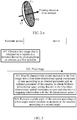
- a panel antenna for example, an antenna shown in FIG. 2-a to FIG.
- a pointing direction of the antenna may be a vertical direction of a plane of a back panel of the antenna, and the direction is from the back panel to a front panel.
- a pointing direction of the antenna is along a vertical line of a plane formed of an outer edge of a reflective surface, and the direction is from a back panel a front panel.
- the definitions of pointing directions of various antennas have general agreements in the industry, and therefore details are not described herein in detail one by one.
- possible characteristic points on several antennas are further provided as examples.
- possible characteristic points are A1, A2, and A3.
- the characteristic points A1, A2, and A3 are located on a back panel or a front panel of the antenna.
- a pointing direction of the antenna is a vertical direction of a plane (for example, the second plane, that is, a plane corresponding to the back panel or the front panel of the antenna) determined by these characteristic points, and the direction is from the back panel to the front panel.
- possible characteristic points are B1, B2, B3, and B4.
- the characteristic points B1, B2, B3, and B4 are all located on a left/right-side surface.
- a pointing direction of the antenna is perpendicular to a plane defined by the characteristic points, and the direction is from a back panel to a front panel.
- possible characteristic points are D1, D2, and D3, and the characteristic points D1, D2, and D3 are located on an outer edge of a reflective surface.
- the pointing direction of the antenna is perpendicular to a plane defined by the characteristic points, and the direction is from a back panel to a front panel.
- characteristic points in the positions in FIG. 2-a to FIG. 2-e are merely possible examples. Characteristic points to be selected in actual applications are not limited to these points, as long as a position relationship between a plane defined by these characteristic points and a pointing direction of an antenna can be determined.
- the internal parameter of the camera is (fx, fy, u0, v0).
- T indicates the origin of the world coordinate system
- R indicates an orthogonal rotation matrix
- f x and f y indicate focal lengths of the camera in an x direction and in a y direction.
- u 0 and v 0 indicate a center of imaging (that is, an intersection between an optical axis and a photosensitive surface of a photosensitive component in the camera).
- the mapping the M characteristic points included in the first image into the first three-dimensional spatial coordinate system according to an internal parameter and an external parameter of the camera may include: mapping the M characteristic points included in the first image into the first three-dimensional spatial coordinate system according to the internal parameter and the external parameter of the camera and a uniform scaling parameter z from a photosensitive component of the camera to the first image.
- the internal parameter of the camera is (fx, fy, u0, v0).
- T indicates the origin of the world coordinate system
- R indicates an orthogonal rotation matrix
- f x and f y indicate focal lengths of the camera in an x direction and in a y direction
- u 0 and v 0 indicate a center of imaging (that is, an intersection between an optical axis and a photosensitive surface of a photosensitive component in the camera)
- z indicates a uniform scaling coefficient from a photosensitive component to a photograph.
- images obtained by the camera by respectively photographing the antenna at multiple different positions may also be used to respectively measure and calculate azimuths and/or downtilts of the antenna, an average value of the azimuths of the antenna that are obtained through multiple times of measurement and calculation is used as the obtained azimuth of the antenna, and an average value of the downtilts of the antenna that are obtained through multiple times of measurement and calculation is used as the obtained downtilt of the antenna.
- the method for measuring an antenna engineering parameter may further include: obtaining, by the measurement device, a second image that is obtained by photographing the antenna at a second position, where the second image includes at least N characteristic points on the antenna, the N characteristic points are characteristic points on a surface of the antenna, the N characteristic points are in a same plane but are not on a same straight line, and N is a positive integer greater than 2; and mapping, by the measurement device, the N characteristic points included in the second image into a second three-dimensional spatial coordinate system, to obtain N three-dimensional space points that are in the second three-dimensional spatial coordinate system and that have a mapping relationship with the N characteristic points, where a second mapping photographing direction may be parallel to the direction of an axis in the second three-dimensional spatial coordinate system, or an included angle having a specified angle exists between a second mapping photographing direction and the direction of an axis in the second three-dimensional spatial coordinate system, and the second mapping photographing direction is obtained by mapping a photographing direction of photographing the second image into the second three-dimensional spatial spatial coordinate
- the obtaining a downtilt of the antenna according to a first angle may include: obtaining the downtilt of the antenna according to the first angle and a third angle (for example, obtaining the downtilt of the antenna according to the first angle, obtaining the downtilt of the antenna according to the third angle, and using an average value of the downtilt of the antenna obtained according to the first angle and the downtilt of the antenna obtained according to the third angle as the downtilt of the antenna obtained according to the first angle and the third angle), where the third angle is equal to an included angle between a normal direction of a fourth plane and a third plane, the third plane may be obtained by mapping the first reference plane into the second three-dimensional spatial coordinate system, and the fourth plane may be determined by the N three-dimensional
- the obtaining a second image that is obtained by photographing the antenna at a second position includes: obtaining the second image that is obtained by the camera by photographing the antenna at the second position.
- the mapping the N characteristic points included in the second image into the second three-dimensional spatial coordinate system includes: mapping the N characteristic points included in the second image into the second three-dimensional spatial coordinate system according to an internal parameter and an external parameter of the camera.
- the method for measuring an antenna engineering parameter may further include, for example: obtaining a second image that is obtained by photographing the antenna at a second position (or a third position), where the second image includes at least N characteristic points on the antenna, the N characteristic points are characteristic points on a surface of the antenna, the N characteristic points are in a same plane but are not on a same straight line, and N is a positive integer greater than 2; and mapping the N characteristic points included in the second image into a second three-dimensional spatial coordinate system, to obtain N three-dimensional space points that are in the second three-dimensional spatial coordinate system and that have a mapping relationship with the N characteristic points, where a second mapping photographing direction may be parallel to the direction of an axis in the second three-dimensional spatial coordinate system, or an included angle having a specified angle exists between a second mapping photographing direction and the direction of an axis in the second three-dimensional spatial coordinate system, and the second mapping photographing direction is obtained by mapping a photographing direction of photographing the second image into the second three-dimensional spatial coordinate system
- the obtaining an azimuth of the antenna according to a second angle may include: obtaining the azimuth of the antenna according to the second angle and a fourth angle (for example, the azimuth of the antenna may be obtaining according to the second angle, the azimuth of the antenna may be obtained according to the fourth angle, and an average value of the azimuth of the antenna obtained according to the second angle and the azimuth of the antenna obtained according to the fourth angle is used as the azimuth of the antenna obtained according to the second angle and the fourth angle), where the fourth angle is equal to an included angle between a third reference direction in a third plane and a projection of a normal direction of a fourth plane on the third plane, the third reference direction may be obtained by mapping a first azimuth reference direction into the second three-dimensional spatial coordinate
- the obtaining the second image that is obtained by photographing the antenna at the second position (or the third position) may include: obtaining the second image that is obtained by the camera by photographing the antenna at the second position (or the third position).
- the mapping the N characteristic points included in the second image into the second three-dimensional spatial coordinate system includes: mapping the N characteristic points included in the second image into the second three-dimensional spatial coordinate system according to an internal parameter and an external parameter of the camera.
- the first reference plane is the horizontal plane
- the normal direction of the fourth plane is parallel to a direction obtained by mapping the pointing direction of the antenna into a second three-dimensional coordinate system
- the first azimuth reference direction is a due north direction
- a third included angle greater than 0 degree exists between the first reference plane and the horizontal plane
- the normal direction of the fourth plane is parallel to a direction obtained by mapping the pointing direction of the antenna into a second three-dimensional coordinate system
- a first included angle greater than 0 degree exists between the first azimuth reference direction and a due north direction
- geometric calibration may be performed on the third angle according to the third included angle to obtain the downtilt of the antenna (the downtilt of the antenna may be equal to the third angle plus/minus the third included angle)
- geometric calibration may be performed on the fourth angle according to the first included angle to obtain the azimuth of the antenna (the azimuth of the antenna is equal to the fourth angle plus/minus the first included angle).
- the rest can be obtained through deduction, for a manner of performing geometric calibration on the third angle to obtain the downtilt of the antenna in another scenario, details are no longer described herein, and for a manner of performing geometric calibration on the fourth angle to obtain the azimuth of the antenna in another scenario, details are no longer described herein.
- the antenna may include k characteristic points, and the N characteristic points may be some or all of the characteristic points of the k characteristic points.
- An intersection set between the N characteristic points and the M characteristic points may be an empty set or a nonempty set.
- an average value of azimuths of the antenna that are obtained through more times of measurement and calculation may also be calculated, and the average value is used as the obtained azimuth of the antenna; an average value of downtilts of the antenna that are obtained through more times of measurement and calculation may also be calculated, and the average value is used as the obtained downtilt of the antenna.
- the first position, the second position, and the third position are different positions, and images obtained by photographing a same antenna at different positions help to obtain an antenna engineering parameter more accurately.
- a terminal device such as a computer, a tablet computer, or a smartphone.
- a measurement device obtains a first image that is obtained by photographing an antenna at a first position, where the first image includes at least M characteristic points on the antenna, the M characteristic points are characteristic points on a surface of the antenna, the M characteristic points are in a same plane but are not on a same straight line, and M is a positive integer greater than 2; and maps the M characteristic points included in the first image into a first three-dimensional spatial coordinate system, to obtain M three-dimensional space points that are in the first three-dimensional spatial coordinate system and that have a mapping relationship with the M characteristic points.
- a mapping relationship between a practical scenario and a mathematical model is established, and a photographing direction of photographing the first image is parallel to the direction of an axis in the first three-dimensional spatial coordinate system.
- a downtilt of the antenna is obtained according to a first angle and/or an azimuth of the antenna is obtained according to a second angle, where the second angle is equal to an included angle between a first reference direction in a first plane and a projection of a normal direction of a second plane on the first plane, and the first angle is equal to an included angle between the normal direction of the second plane and the first plane.
- a photograph of a practical scenario is used to establish a mapping relationship between a practical scenario and a mathematical model, so as to calculate an engineering parameter of an antenna by using such a mathematical model.
- the solution provided in this embodiment of the present invention helps to improve precision of an obtained antenna engineering parameter, thereby providing a basis for improvement of reception and transmission performance of a signal.
- a solution also helps to greatly reduce difficulty of measuring an antenna engineering parameter.
- FIG. 3 is a schematic flowchart of another method for measuring an antenna engineering parameter according to another embodiment of the present invention.
- a terminal device a portable terminal device such as a mobile phone or a tablet computer
- a remote measurement device a server is used as an example below
- the another method for measuring an antenna engineering parameter according to the another embodiment of the present invention may include the following content:
- the first image includes at least M characteristic points on the antenna, the M characteristic points are characteristic points on a surface of the antenna, the M characteristic points are in a same plane but are not on a same straight line, and M is a positive integer greater than 2.
- the antenna may include k characteristic points, and the M characteristic points may be some or all of the characteristic points of the k characteristic points.
- the terminal device sends the first image to a server.
- the server receives the first image that is obtained by the camera in the terminal device by photographing the antenna at the first position, and maps the M characteristic points included in the first image into a first three-dimensional spatial coordinate system according to an internal parameter and an external parameter of the camera, to obtain M three-dimensional space points that are in the first three-dimensional spatial coordinate system and that have a mapping relationship with the M characteristic points.
- the server obtains a downtilt of the antenna according to a first angle and/or obtains an azimuth of the antenna according to a second angle.
- the second angle is equal to an included angle between a first reference direction in a first plane and a projection of a normal direction of a second plane on the first plane
- the first angle is equal to an included angle between the normal direction of the second plane and the first plane
- the first plane is obtained by mapping a first reference plane into the first three-dimensional spatial coordinate system
- the second plane is determined by the M three-dimensional space points
- the first reference direction is obtained by mapping a first azimuth reference direction into the first three-dimensional spatial coordinate system.
- the server may further feed back the obtained downtilt of the antenna and/or the obtained azimuth of the antenna to the terminal device.
- the first azimuth reference direction may also be, for example, a due east direction or a due west direction, or a fifth included angle greater than 0 degree exists between the first azimuth reference direction and a due east direction (that is, the first azimuth reference direction can be determined according to the due east direction and the fifth included angle), or a sixth included angle greater than 0 degree exists between the first azimuth reference direction and a due east direction (that is, the first azimuth reference direction can be determined according to the due west direction and the sixth included angle).
- the first reference plane may be a horizontal plane, or a third included angle greater than 0 degree exists between the first reference plane and a horizontal plane (that is, the first reference plane can be determined according to the horizontal plane and the third included angle).
- the first reference plane may also be a vertical plane, or a seventh included angle greater than 0 degree exists between the first reference plane and a vertical plane (that is, the first reference plane can be determined according to the vertical plane and the seventh included angle).
- the terminal device may determine a due north direction or a due south direction by using a magnetic flux sensor, a compass, or the like in the terminal device.
- the terminal device may also obtain a gravity direction by using a gravity sensor, and a vertical plane of the gravity direction is the horizontal plane.
- a gravity direction, a due north direction, or the like may be determined by using some reference objects in the photographed image.
- an antenna pole is usually perpendicular to a ground surface. Therefore, a vertical plane may be determined according to a pointing direction of an antenna pole. When the vertical plane is determined, the horizontal plane is determined.
- the horizontal plane may be mapped into a three-dimensional coordinate system and used as a reference plane.
- the first reference plane in step 103 may be the horizontal plane, and the first plane may be obtained by mapping the horizontal plane into the first three-dimensional spatial coordinate system. It may be understood that, a scenario in which a reference direction or a reference plane is determined by using another reference object may be similar thereto.
- the normal direction of the second plane may be, for example, parallel to a direction obtained by mapping a pointing direction of the antenna into a first three-dimensional coordinate system.
- a fourth included angle greater than 0 degree exists between the normal direction of the second plane and the direction obtained by mapping the pointing direction of the antenna into the first three-dimensional coordinate system (that is, the direction obtained by mapping the pointing direction of the antenna into the first three-dimensional coordinate system is determined according to the normal direction of the second plane and the fourth included angle).
- the mapping the M characteristic points included in the first image into the first three-dimensional spatial coordinate system according to an internal parameter and an external parameter of the camera may include: mapping the M characteristic points included in the first image into the first three-dimensional spatial coordinate system according to the internal parameter and the external parameter of the camera and a uniform scaling parameter z from a photosensitive component of the camera to the first image.
- the internal parameter of the camera is (fx, fy, u0, v0); and a mapping relationship between coordinates ( u p , v p ) of any characteristic point of the M characteristic points included in the first image and coordinates ( x w , y w , z w ) of a three-dimensional space point obtained by mapping the characteristic point into the first three-dimensional spatial coordinate system may be shown in the formula 2.
- the terminal device may also use images obtained by the camera by respectively photographing the antenna at multiple different positions to respectively measure and calculate azimuths and/or downtilts of the antenna, use an average value of the azimuths of the antenna that are obtained through multiple times of measurement and calculation as the obtained azimuth of the antenna, and use an average value of the downtilts of the antenna that are obtained through multiple times of measurement and calculation as the obtained downtilt of the antenna.
- the server may further obtain a second image that is obtained by the camera in the terminal device by photographing the antenna at a second position, where the second image includes at least N characteristic points on the antenna, the N characteristic points are characteristic points on a surface of the antenna, the N characteristic points are in a same plane but are not on a same straight line, and N is a positive integer greater than 2; and map the N characteristic points included in the second image into a second three-dimensional spatial coordinate system according to an internal parameter and an external parameter of the camera, to obtain N three-dimensional space points that are in the second three-dimensional spatial coordinate system and that have a mapping relationship with the N characteristic points, where a second mapping photographing direction may be parallel to the direction of an axis in the second three-dimensional spatial coordinate system, or an included angle having a specified angle exists between a second mapping photographing direction and the direction of an axis in the second three-dimensional spatial coordinate system, and the second mapping photographing direction is obtained by mapping a photographing direction of photographing the second image by the camera into the second three-dimensional
- the server may further obtain a second image that is obtained by the camera in the terminal device by photographing the antenna at a second position (or a third position), where the second image includes at least N characteristic points on the antenna, the N characteristic points are characteristic points on a surface of the antenna, the N characteristic points are in a same plane but are not on a same straight line, and N is a positive integer greater than 2; and map the N characteristic points included in the second image into a second three-dimensional spatial coordinate system according to an internal parameter and an external parameter of the camera, to obtain N three-dimensional space points that are in the second three-dimensional spatial coordinate system and that have a mapping relationship with the N characteristic points, where a second mapping photographing direction may be parallel to the direction of an axis in the second three-dimensional spatial coordinate system, or an included angle having a specified angle exists between a second mapping photographing direction and the direction of an axis in the second three-dimensional spatial coordinate system, and the second mapping photographing direction is obtained by mapping a photographing direction of photographing the second image by the
- the obtaining an azimuth of the antenna according to a second angle may specifically include: obtaining the azimuth of the antenna according to the second angle and a fourth angle, where the fourth angle is equal to an included angle between a third reference direction in a third plane and a projection of a normal direction of a fourth plane on the third plane, the third reference direction may be obtained by mapping a first azimuth reference direction into the second three-dimensional spatial coordinate system, the third plane may be obtained by mapping the first reference plane into the second three-dimensional spatial coordinate system, and the fourth plane is determined by the N three-dimensional space points.
- the antenna may include k characteristic points, and the M characteristic points may be some or all of the characteristic points of the k characteristic points.
- An intersection set between the N characteristic points and the M characteristic points may be an empty set or a nonempty set.
- the server may also calculate an average value of azimuths of the antenna that are obtained through more times of measurement and calculation, and use the average value as the obtained azimuth of the antenna; or may calculate an average value of downtilts of the antenna that are obtained through more times of measurement and calculation, and use the average value as the obtained downtilt of the antenna.
- the server may also calculate an average value of azimuths of the antenna that are obtained through more times of measurement and calculation, and use the average value as the obtained azimuth of the antenna; or may calculate an average value of downtilts of the antenna that are obtained through more times of measurement and calculation, and use the average value as the obtained downtilt of the antenna.
- the first position, the second position, and the third position are different positions, and images obtained by photographing a same antenna at different positions help to obtain an antenna engineering parameter more accurately.
- FIG. 4-a is the first image that is obtained by the camera in the terminal device by photographing the antenna at the first position, where star-shaped symbols are positions of marked characteristic points.
- FIG. 4-b may be regarded as an equivalent geometric pattern of the antenna in the first image, where characteristic points, that is, a characteristic point A1, a characteristic point A2, and a characteristic point A3 that are located on a same plane are provided on the antenna.
- the server may map the M characteristic points included in the first image into the first three-dimensional spatial coordinate system according to an internal parameter and an external parameter of the camera, to obtain three three-dimensional space points that are in the first three-dimensional spatial coordinate system and that have a mapping relationship with the three characteristic points. For example, as shown in FIG. 4-c , it is assumed that a direction of a y axis in the first three-dimensional spatial coordinate system is parallel to the first mapping photographing direction, where the first mapping photographing direction is a direction obtained by mapping a photographing direction of the first image into the first three-dimensional spatial coordinate system.
- characteristic points A1, A2, and A3 are mapped into the first three-dimensional spatial coordinate system, to obtain three three-dimensional space points A1', A2', and A3' that are in the first three-dimensional spatial coordinate system and that have a mapping relationship with the characteristic points A1, A2, and A3.
- FIG. 4-d shows a characteristic plane that is determined by the three-dimensional space points A1', A2', and A3' together (the characteristic plane is, for example, the second plane in the foregoing embodiment).
- the characteristic plane is a plane indicated by a slant-line shadow in FIG. 4-d , and a normal direction of the characteristic plane may be a direction pointed by a dashed-line arrow shown in FIG. 4-d .
- the normal direction of the characteristic plane is parallel to a direction obtained by mapping the pointing direction of the antenna into the first three-dimensional coordinate system is used.
- a scenario in which the fourth included angle greater than 0 degree exists between the normal direction of the second plane and the direction obtained by mapping the pointing direction of the antenna into the first three-dimensional coordinate system can be obtained through deduction.
- FIG. 4-e shows a first reference direction obtained by mapping the first azimuth reference direction into the first three-dimensional coordinate system.
- the first azimuth reference direction is a due north direction.
- the terminal device such as a smartphone or a tablet computer
- the terminal device may determine a due north direction or a due south direction by using a magnetic flux sensor, a compass, or the like in the terminal device.
- the terminal device may obtain a gravity direction by using a gravity sensor, and a vertical plane of the gravity direction is the horizontal plane.
- a gravity direction, a due north direction, or the like may be determined by using some reference objects in the photographed image.
- FIG. 4-f shows the first plane that is obtained by mapping the first reference plane into the first three-dimensional coordinate system, where an example in which the first reference plane is the horizontal plane is used, and the first plane is the plane indicated by the point shadow in FIG. 4-f .
- a projection of a normal direction s3 of the characteristic plane on the first plane is s2, and an azimuth ⁇ ⁇ of the antenna is equal to an included angle between the projection s2 of the normal direction s3 of the characteristic plane on the first plane and a first reference direction s5.
- a downtilt ⁇ ⁇ of the antenna is equal to an included angle between the normal direction s3 of the characteristic plane and the projection s2 of the normal direction s3 of the characteristic plane on the first plane.
- ⁇ y is an included angle between the first mapping photographing direction y and the first reference direction s5.
- the downtilt ⁇ ⁇ of the antenna may be determined according to the characteristic plane.
- the azimuth ⁇ ⁇ of the antenna may be determined according to the characteristic plane.
- a server obtains a first image that is obtained by a camera by photographing an antenna at a first position, where the first image includes at least M characteristic points on the antenna, the M characteristic points are characteristic points on a surface of the antenna, the M characteristic points are in a same plane but are not on a same straight line, and M is a positive integer greater than 2; and maps the M characteristic points included in the first image into a first three-dimensional spatial coordinate system according to an internal parameter and an external parameter of the camera, to obtain M three-dimensional space points that are in the first three-dimensional spatial coordinate system and that have a mapping relationship with the M characteristic points.
- a mapping relationship between a practical scenario and a mathematical model is established, and a photographing direction of photographing the first image by the camera is parallel to the direction of an axis in the first three-dimensional spatial coordinate system.
- a downtilt of the antenna is obtained according to a first angle and/or an azimuth of the antenna is obtained according to a second angle, where the second angle is equal to an included angle between a first reference direction in a first plane and a projection of a normal direction of a second plane on the first plane, and the first angle is equal to an included angle between the normal direction of the second plane and the first plane.
- FIG. 5 is a schematic flowchart of another method for measuring an antenna engineering parameter according to another embodiment of the present invention.
- a terminal device cooperates with a remote measurement device (a server is used as an example) to implement measurement on an antenna engineering parameter.
- the another method for measuring an antenna engineering parameter according to the another embodiment of the present invention may include the following content:
- the first image includes at least M characteristic points on the antenna, the M characteristic points are characteristic points on a surface of the antenna, the M characteristic points are in a same plane but are not on a same straight line, and M is a positive integer greater than 2.
- the antenna may include k characteristic points, and the M characteristic points may be some or all of the characteristic points of the k characteristic points.
- the terminal device maps the M characteristic points included in the first image into a first three-dimensional spatial coordinate system according to an internal parameter and an external parameter of the camera, to obtain M three-dimensional space points that are in the first three-dimensional spatial coordinate system and that have a mapping relationship with the M characteristic points.
- a first mapping photographing direction may be parallel to the direction of an axis in the first three-dimensional spatial coordinate system, or an included angle having a specified angle exists between a first mapping photographing direction and the direction of an axis in the first three-dimensional spatial coordinate system, and the first mapping photographing direction is obtained by mapping a photographing direction of photographing the first image by the camera into the first three-dimensional spatial coordinate system.
- an example in which the first mapping photographing direction is parallel to the direction of an axis (for example, a y axis) in the first three-dimensional spatial coordinate system is mainly used.
- the terminal device obtains a downtilt of the antenna according to a first angle and/or obtains an azimuth of the antenna according to a second angle, where the second angle is equal to an included angle between a first reference direction in a first plane and a projection of a normal direction of a second plane on the first plane, the first angle is equal to an included angle between the normal direction of the second plane and the first plane, the first plane is obtained by mapping a first reference plane into the first three-dimensional spatial coordinate system, the second plane is determined by the M three-dimensional space points, and the first reference direction is obtained by mapping a first azimuth reference direction into the first three-dimensional spatial coordinate system.
- the terminal device may further feed back the obtained downtilt of the antenna and/or the obtained azimuth of the antenna to a server.
- the first azimuth reference direction may be, for example, a due north direction or a due south direction, or a first included angle greater than 0 degree exists between the first azimuth reference direction and a due north direction (that is, the first azimuth reference direction can be determined according to the due north direction and the first included angle), or a second included angle greater than 0 degree exists between the first azimuth reference direction and a due south direction (that is, the first azimuth reference direction can be determined according to the due south direction and the second included angle).
- the first azimuth reference direction may also be, for example, a due east direction or a due west direction, or a fifth included angle greater than 0 degree exists between the first azimuth reference direction and a due east direction (that is, the first azimuth reference direction can be determined according to the due east direction and the fifth included angle), or a sixth included angle greater than 0 degree exists between the first azimuth reference direction and a due east direction (that is, the first azimuth reference direction can be determined according to the due west direction and the sixth included angle).
- the first reference plane may be a horizontal plane, or a third included angle greater than 0 degree exists between the first reference plane and a horizontal plane (that is, the first reference plane can be determined according to the horizontal plane and the third included angle).
- the first reference plane may also be a vertical plane, or a seventh included angle greater than 0 degree exists between the first reference plane and a vertical plane (that is, the first reference plane can be determined according to the vertical plane and the seventh included angle).
- the terminal device may determine a due north direction or a due south direction by using a magnetic flux sensor, a compass, or the like in the terminal device.
- the terminal device may also obtain a gravity direction by using a gravity sensor, and a vertical plane of the gravity direction is the horizontal plane.
- a gravity direction, a due north direction, or the like may be determined by using some reference objects in the photographed image.
- an antenna pole is usually perpendicular to a ground surface. Therefore, a vertical plane may be determined according to a pointing direction of an antenna pole. When the vertical plane is determined, the horizontal plane is determined.
- the horizontal plane may be mapped into a three-dimensional coordinate system and used as a reference plane.
- the first reference plane in step 103 may be the horizontal plane, and the first plane may be obtained by mapping the horizontal plane into the first three-dimensional spatial coordinate system. It may be understood that, a scenario in which a reference direction or a reference plane is determined by using another reference object may be similar thereto.
- the normal direction of the second plane may be, for example, parallel to a direction obtained by mapping a pointing direction of the antenna into a first three-dimensional coordinate system.
- a fourth included angle greater than 0 degree exists between the normal direction of the second plane and the direction obtained by mapping the pointing direction of the antenna into the first three-dimensional coordinate system (that is, the direction obtained by mapping the pointing direction of the antenna into the first three-dimensional coordinate system is determined according to the normal direction of the second plane and the fourth included angle).
- the mapping the M characteristic points included in the first image into the first three-dimensional spatial coordinate system according to an internal parameter and an external parameter of the camera may include: mapping the M characteristic points included in the first image into the first three-dimensional spatial coordinate system according to the internal parameter and the external parameter of the camera and a uniform scaling parameter z from a photosensitive component of the camera to the first image.
- the internal parameter of the camera is (fx, fy, u0, v0); and a mapping relationship between coordinates ( u p , v p ) of any characteristic point of the M characteristic points included in the first image and coordinates ( x w , y w , z w ) of a three-dimensional space point obtained by mapping the characteristic point into the first three-dimensional spatial coordinate system may be shown in the formula 2.
- the terminal device may also use images obtained by the camera by respectively photographing the antenna at multiple different positions to respectively measure and calculate azimuths and/or downtilts of the antenna, use an average value of the azimuths of the antenna that are obtained through multiple times of measurement and calculation as the obtained azimuth of the antenna, and use an average value of the downtilts of the antenna that are obtained through multiple times of measurement and calculation as the obtained downtilt of the antenna.
- the terminal device may further obtain a second image that is obtained by the camera by photographing the antenna at a second position, where the second image includes at least N characteristic points on the antenna, the N characteristic points are characteristic points on a surface of the antenna, the N characteristic points are in a same plane but are not on a same straight line, and N is a positive integer greater than 2; and map the N characteristic points included in the second image into a second three-dimensional spatial coordinate system according to an internal parameter and an external parameter of the camera, to obtain N three-dimensional space points that are in the second three-dimensional spatial coordinate system and that have a mapping relationship with the N characteristic points, where a second mapping photographing direction may be parallel to the direction of an axis in the second three-dimensional spatial coordinate system, or an included angle having a specified angle exists between a second mapping photographing direction and the direction of an axis in the second three-dimensional spatial coordinate system, and the second mapping photographing direction is obtained by mapping a photographing direction of photographing the second image by the camera into the second three-dimensional spatial coordinate system
- the obtaining a downtilt of the antenna according to a first angle may include: obtaining the downtilt of the antenna according to the first angle and a third angle, where the third angle is equal to an included angle between a normal direction of a fourth plane and a third plane, the third plane may be obtained by mapping the first reference plane into the second three-dimensional spatial coordinate system, and the fourth plane may be determined by the N three-dimensional space points.
- the terminal device may further obtain a second image that is obtained by the camera by photographing the antenna at a second position (or a third position), where the second image includes at least N characteristic points on the antenna, the N characteristic points are characteristic points on a surface of the antenna, the N characteristic points are in a same plane but are not on a same straight line, and N is a positive integer greater than 2; and map the N characteristic points included in the second image into a second three-dimensional spatial coordinate system according to an internal parameter and an external parameter of the camera, to obtain N three-dimensional space points that are in the second three-dimensional spatial coordinate system and that have a mapping relationship with the N characteristic points, where a second mapping photographing direction may be parallel to the direction of an axis in the second three-dimensional spatial coordinate system, or an included angle having a specified angle exists between a second mapping photographing direction and the direction of an axis in the second three-dimensional spatial coordinate system, and the second mapping photographing direction is obtained by mapping a photographing direction of photographing the second image by the camera into the
- the obtaining an azimuth of the antenna according to a second angle may specifically include: obtaining the azimuth of the antenna according to the second angle and a fourth angle, where the fourth angle is equal to an included angle between a third reference direction in a third plane and a projection of a normal direction of a fourth plane on the third plane, the third reference direction may be obtained by mapping a first azimuth reference direction into the second three-dimensional spatial coordinate system, the third plane may be obtained by mapping the first reference plane into the second three-dimensional spatial coordinate system, and the fourth plane is determined by the N three-dimensional space points.
- the antenna may include k characteristic points, and the M characteristic points may be some or all of the characteristic points of the k characteristic points.
- An intersection set between the N characteristic points and the M characteristic points may be an empty set or a nonempty set.
- the terminal device may also calculate an average value of azimuths of the antenna that are obtained through more times of measurement and calculation, and use the average value as the obtained azimuth of the antenna; or may calculate an average value of downtilts of the antenna that are obtained through more times of measurement and calculation, and use the average value as the obtained downtilt of the antenna.
- the terminal device may also calculate an average value of azimuths of the antenna that are obtained through more times of measurement and calculation, and use the average value as the obtained azimuth of the antenna; or may calculate an average value of downtilts of the antenna that are obtained through more times of measurement and calculation, and use the average value as the obtained downtilt of the antenna.
- the first position, the second position, and the third position are different positions, and images obtained by photographing a same antenna at different positions help to obtain an antenna engineering parameter more accurately.
- a terminal device obtains a first image that is obtained by a camera by photographing an antenna at a first position, where the first image includes at least M characteristic points on the antenna, the M characteristic points are characteristic points on a surface of the antenna, the M characteristic points are in a same plane but are not on a same straight line, and M is a positive integer greater than 2; and maps the M characteristic points included in the first image into a first three-dimensional spatial coordinate system according to an internal parameter and an external parameter of the camera, to obtain M three-dimensional space points that are in the first three-dimensional spatial coordinate system and that have a mapping relationship with the M characteristic points.
- a mapping relationship between a practical scenario and a mathematical model is established, and a photographing direction of photographing the first image by the camera is parallel to the direction of an axis in the first three-dimensional spatial coordinate system.
- a downtilt of the antenna is obtained according to a first angle and/or an azimuth of the antenna is obtained according to a second angle, where the second angle is equal to an included angle between a first reference direction in a first plane and a projection of a normal direction of a second plane on the first plane, and the first angle is equal to an included angle between the normal direction of the second plane and the first plane.
- a photograph of a practical scenario is used to establish a mapping relationship between a practical scenario and a mathematical model, so as to to calculate an engineering parameter of an antenna by using such a mathematical model.
- the solution provided in this embodiment of the present invention helps to improve precision of an obtained antenna engineering parameter, thereby providing a basis for improvement of reception and transmission performance of a signal.
- a solution also helps to greatly reduce difficulty of measuring an antenna engineering parameter.
- an embodiment of the present invention provides an apparatus 600 for measuring an antenna engineering parameter, where the apparatus 600 includes:
- the obtaining unit 610 is configured to obtain a first image that is obtained by photographing an antenna at a first position.
- the obtaining unit 610 may be specifically configured to obtain the first image that is obtained by a camera by photographing the antenna at the first position.
- the first image includes at least M characteristic points on the antenna, the M characteristic points are characteristic points on a surface of the antenna, the M characteristic points are in a same plane but are not on a same straight line, and M is a positive integer greater than 2.
- the antenna may include k characteristic points, and the M characteristic points may be some or all of the characteristic points of the k characteristic points.
- a position relationship between a plane defined by these characteristic points and a pointing direction of the antenna may be determined.
- the position relationship between the plane defined by these characteristic points and the pointing direction of the antenna may be a parallel relationship, a perpendicular relationship, or a relationship of another specific angle.
- the mapping unit 620 is configured to map the M characteristic points included in the first image into a first three-dimensional spatial coordinate system, to obtain M three-dimensional space points that are in the first three-dimensional spatial coordinate system and that have a mapping relationship with the M characteristic points, where a first mapping photographing direction is parallel to a direction of an axis in the first three-dimensional spatial coordinate system, or an included angle having a specified angle exists between a first mapping photographing direction and a direction of an axis in the first three-dimensional spatial coordinate system, and the first mapping photographing direction is obtained by mapping a photographing direction of photographing the first image into the first three-dimensional spatial coordinate system.
- the mapping unit 620 may be specifically configured to map the M characteristic points included in the first image into the first three-dimensional spatial coordinate system according to an internal parameter and an external parameter of the camera, to obtain M three-dimensional space points that are in the first three-dimensional spatial coordinate system and that have a mapping relationship with the M characteristic points.
- the estimation unit 630 is configured to: obtain a downtilt of the antenna according to a first angle and/or obtain an azimuth of the antenna according to a second angle, where the second angle is equal to an included angle between a first reference direction in a first plane and a projection of a normal direction of a second plane on the first plane, the first angle is equal to an included angle between the normal direction of the second plane and the first plane, the first plane is obtained by mapping a first reference plane into the first three-dimensional spatial coordinate system, the second plane is determined by the M three-dimensional space points, and the first reference direction is obtained by mapping a first azimuth reference direction into the first three-dimensional spatial coordinate system.
- the first azimuth reference direction may be, for example, a due north direction or a due south direction, or a first included angle greater than 0 degree exists between the first azimuth reference direction and a due north direction (that is, the first azimuth reference direction can be determined according to the due north direction and the first included angle), or a second included angle greater than 0 degree exists between the first azimuth reference direction and a due south direction (that is, the first azimuth reference direction can be determined according to the due south direction and the second included angle).
- the first azimuth reference direction may also be, for example, a due east direction or a due west direction, or a fifth included angle greater than 0 degree exists between the first azimuth reference direction and a due east direction (that is, the first azimuth reference direction can be determined according to the due east direction and the fifth included angle), or a sixth included angle greater than 0 degree exists between the first azimuth reference direction and a due east direction (that is, the first azimuth reference direction can be determined according to the due west direction and the sixth included angle).
- the first reference plane may be a horizontal plane, or a third included angle greater than 0 degree exists between the first reference plane and a horizontal plane (that is, the first reference plane can be determined according to the horizontal plane and the third included angle).
- the first reference plane may also be a vertical plane, or a seventh included angle greater than 0 degree exists between the first reference plane and a vertical plane (that is, the first reference plane can be determined according to the vertical plane and the seventh included angle).
- the apparatus 600 for measuring an antenna engineering parameter is a terminal device.
- the terminal device may determine a due north direction or a due south direction by using a magnetic flux sensor, a compass, or the like in the terminal device.
- the terminal device may also obtain a gravity direction by using a gravity sensor, and a vertical plane of the gravity direction is the horizontal plane.
- a gravity direction, a due north direction, or the like may be determined by using some reference objects in the photographed image.
- an antenna pole is usually perpendicular to a ground surface. Therefore, a vertical plane may be determined according to a pointing direction of an antenna pole. When the vertical plane is determined, the horizontal plane is determined.
- the horizontal plane may be mapped into a three-dimensional coordinate system and used as a reference plane, for example, the first reference plane may be the horizontal plane, and the first plane may be obtained by mapping the horizontal plane into the first three-dimensional spatial coordinate system. It may be understood that, a scenario in which a reference direction or a reference plane is determined by using another reference object may be similar thereto.
- the normal direction of the second plane may be, for example, parallel to a direction obtained by mapping the pointing direction of the antenna into a first three-dimensional coordinate system.
- a fourth included angle greater than 0 degree exists between the normal direction of the second plane and the direction obtained by mapping the pointing direction of the antenna into the first three-dimensional coordinate system (that is, the direction obtained by mapping the pointing direction of the antenna into the first three-dimensional coordinate system is determined according to the normal direction of the second plane and the fourth included angle).
- the mapping unit 620 is specifically configured to map the M characteristic points included in the first image into the first three-dimensional spatial coordinate system according to an internal parameter and an external parameter of the camera and a uniform scaling parameter z from a photosensitive component of the camera to the first image.
- first reference plane is the horizontal plane
- a direction obtained by mapping the pointing direction of the antenna into the first three-dimensional coordinate system may be parallel to the normal direction of the second plane
- the first azimuth reference direction is a due north direction, so that the downtilt of the antenna obtained according to the first angle is equal to the first angle, and the azimuth of the antenna obtained according to the second angle is equal to the second angle.
- a third included angle greater than 0 degree exists between the first reference plane and the horizontal plane
- a direction obtained by mapping the pointing direction of the antenna into the first three-dimensional coordinate system may be parallel to the normal direction of the second plane
- a first included angle greater than 0 degree exists between the first azimuth reference direction and a due north direction
- geometric calibration may be performed on the first angle according to the third included angle to obtain the downtilt of the antenna (the downtilt of the antenna is equal to the first angle plus/minus the third included angle)
- geometric calibration may be performed on the second angle according to the first included angle to obtain the azimuth of the antenna (the azimuth of the antenna is equal to the second angle plus/minus the first included angle).
- the rest can be obtained through deduction, for a manner of performing geometric calibration on the first angle to obtain the downtilt of the antenna in another scenario, details are no longer described herein, and for a manner of performing geometric calibration on the second angle to obtain the azimuth of the antenna in another scenario, details are no longer described herein.
- the obtaining unit 610 may be further configured to obtain a second image that is obtained by photographing the antenna at a second position, where the second image includes at least N characteristic points on the antenna, the N characteristic points are characteristic points on a surface of the antenna, the N characteristic points are in a same plane but are not on a same straight line, and N is a positive integer greater than 2.
- the mapping unit 620 may be further configured to map the N characteristic points included in the second image into a second three-dimensional spatial coordinate system, to obtain N three-dimensional space points that are in the second three-dimensional spatial coordinate system and that have a mapping relationship with the N characteristic points, where a second mapping photographing direction is parallel to a direction of an axis in the second three-dimensional spatial coordinate system, or an included angle having a specified angle exists between a second mapping photographing direction and a direction of an axis in the second three-dimensional spatial coordinate system, and the second mapping photographing direction is obtained by mapping a photographing direction of photographing the second image into the second three-dimensional spatial coordinate system.
- the estimation unit 630 may be specifically configured to obtain the downtilt of the antenna according to the first angle and a third angle, where the third angle is equal to an included angle between a normal direction of a fourth plane and a third plane, the third plane is obtained by mapping the first reference plane into the second three-dimensional spatial coordinate system, and the fourth plane is determined by the N three-dimensional space points.
- the obtaining unit 610 is further configured to obtain a second image that is obtained by photographing the antenna at a second position, where the second image includes at least N characteristic points on the antenna, the N characteristic points are characteristic points on a surface of the antenna, the N characteristic points are in a same plane but are not on a same straight line, and N is a positive integer greater than 2.
- the mapping unit 620 is further configured to map the N characteristic points included in the second image into a second three-dimensional spatial coordinate system, to obtain N three-dimensional space points that are in the second three-dimensional spatial coordinate system and that have a mapping relationship with the N characteristic points, where a second mapping photographing direction is parallel to a direction of an axis in the second three-dimensional spatial coordinate system, or an included angle having a specified angle exists between a second mapping photographing direction and a direction of an axis in the second three-dimensional spatial coordinate system, and the second mapping photographing direction is obtained by mapping a photographing direction of photographing the second image into the second three-dimensional spatial coordinate system.
- the estimation unit 630 is specifically configured to obtain the azimuth of the antenna according to the second angle and a fourth angle, where the fourth angle is equal to an included angle between a first reference direction in a third plane and a projection of a normal direction of a fourth plane on the third plane, the first reference direction is obtained by mapping the first azimuth reference direction into the first three-dimensional spatial coordinate system, the third plane is obtained by mapping the first reference plane into the second three-dimensional spatial coordinate system, and the fourth plane is determined by the N three-dimensional space points.
- the obtaining unit 610 is specifically configured to obtain the second image that is obtained by the camera by photographing the antenna at the second position.
- the mapping unit 620 may be specifically configured to map the N characteristic points included in the second image into the second three-dimensional spatial coordinate system according to an internal parameter and an external parameter of the camera.
- the first reference plane is the horizontal plane
- the normal direction of the fourth plane is parallel to a direction obtained by mapping the pointing direction of the antenna into a second three-dimensional coordinate system
- the first azimuth reference direction is a due north direction
- a third included angle greater than 0 degree exists between the first reference plane and the horizontal plane
- the normal direction of the fourth plane is parallel to a direction obtained by mapping the pointing direction of the antenna into a second three-dimensional coordinate system
- a first included angle greater than 0 degree exists between the first azimuth reference direction and a due north direction
- geometric calibration may be performed on the third angle according to the third included angle to obtain the downtilt of the antenna (the downtilt of the antenna may be equal to the third angle plus/minus the third included angle)
- geometric calibration may be performed on the fourth angle according to the first included angle to obtain the azimuth of the antenna (the azimuth of the antenna is equal to the fourth angle plus/minus the first included angle).
- the rest can be obtained through deduction, for a manner of performing geometric calibration on the third angle to obtain the downtilt of the antenna in another scenario, details are no longer described herein, and for a manner of performing geometric calibration on the fourth angle to obtain the azimuth of the antenna in another scenario, details are no longer described herein.
- the antenna may include k characteristic points, and the N characteristic points may be some or all of the characteristic points of the k characteristic points.
- An intersection set between the N characteristic points and the M characteristic points may be an empty set or a nonempty set.
- an average value of azimuths of the antenna that are obtained through more times of measurement and calculation may also be calculated, and the average value is used as the obtained azimuth of the antenna; an average value of downtilts of the antenna that are obtained through more times of measurement and calculation may also be calculated, and the average value is used as the obtained downtilt of the antenna.
- the first position and the second position are different positions, and images obtained by photographing a same antenna at different positions help to obtain an antenna engineering parameter more accurately.
- the apparatus 600 for measuring an antenna engineering parameter in this embodiment obtains a first image that is obtained by photographing an antenna at a first position, where the first image includes at least M characteristic points on the antenna, the M characteristic points are characteristic points on a surface of the antenna, the M characteristic points are in a same plane but are not on a same straight line, and M is a positive integer greater than 2; and maps the M characteristic points included in the first image into a first three-dimensional spatial coordinate system, to obtain M three-dimensional space points that are in the first three-dimensional spatial coordinate system and that have a mapping relationship with the M characteristic points.
- a mapping relationship between a practical scenario and a mathematical model is established, where a photographing direction of photographing the first image is parallel to the direction of an axis in the first three-dimensional spatial coordinate system.
- a downtilt of the antenna is obtained according to a first angle and/or an azimuth of the antenna is obtained according to a second angle, where the second angle is equal to an included angle between a first reference direction in a first plane and a projection of a normal direction of a second plane on the first plane, and the first angle is equal to an included angle between the normal direction of the second plane and the first plane.
- a photograph of a practical scenario is used to establish a mapping relationship between a practical scenario and a mathematical model, so as to calculate an engineering parameter of an antenna by using such a mathematical model.
- the solution in this embodiment helps to improve precision of an obtained antenna engineering parameter, thereby providing a basis for improvement of reception and transmission performance of a signal.
- a solution also helps to greatly reduce difficulty of measuring an antenna engineering parameter.
- FIG. 7 is a schematic diagram of a measurement device 700 according to an embodiment of the present invention.
- the measurement device 700 includes: at least one bus 701, at least one processor 702 connected to the bus 701, and at least one memory 703 connected to the bus 701.
- the processor 702 invokes, by using the bus 701, code stored in the memory 703 to: obtain a first image that is obtained by photographing an antenna at a first position, where the first image includes at least M characteristic points on the antenna, the M characteristic points are characteristic points on a surface of the antenna, the M characteristic points are in a same plane but are not on a same straight line, and M is a positive integer greater than 2; and map the M characteristic points included in the first image into a first three-dimensional spatial coordinate system, to obtain M three-dimensional space points that are in the first three-dimensional spatial coordinate system and that have a mapping relationship with the M characteristic points, where a first mapping photographing direction is parallel to a direction of an axis in the first three-dimensional spatial coordinate system, or an included angle having a specified angle exists between a first mapping photographing direction and a direction of an axis in the first three-dimensional spatial coordinate system, and the first mapping photographing direction is obtained by mapping a photographing direction of photographing the first image into the first three-dimensional spatial coordinate system; and
- the first azimuth reference direction may be, for example, a due north direction or a due south direction, or a first included angle greater than 0 degree exists between the first azimuth reference direction and a due north direction (that is, the first azimuth reference direction can be determined according to the due north direction and the first included angle), or a second included angle greater than 0 degree exists between the first azimuth reference direction and a due south direction (that is, the first azimuth reference direction can be determined according to the due south direction and the second included angle).
- the first azimuth reference direction may also be, for example, a due east direction or a due west direction, or a fifth included angle greater than 0 degree exists between the first azimuth reference direction and a due east direction (that is, the first azimuth reference direction can be determined according to the due east direction and the fifth included angle), or a sixth included angle greater than 0 degree exists between the first azimuth reference direction and a due east direction (that is, the first azimuth reference direction can be determined according to the due west direction and the sixth included angle).
- the first reference plane may be a horizontal plane, or a third included angle greater than 0 degree exists between the first reference plane and a horizontal plane (that is, the first reference plane can be determined according to the horizontal plane and the third included angle).
- the first reference plane may also be a vertical plane, or a seventh included angle greater than 0 degree exists between the first reference plane and a vertical plane (that is, the first reference plane can be determined according to the vertical plane and the seventh included angle).
- the processor 702 in the aspect of obtaining a first image that is obtained by photographing an antenna at a first position, is specifically configured to obtain the first image that is obtained by a camera by photographing the antenna at the first position.
- the processor 702 is specifically configured to obtain, according to an internal parameter and an external parameter of the camera, the first image that is obtained by the camera by photographing the antenna at the first position.
- the terminal device may determine a due north direction or a due south direction by using a magnetic flux sensor, a compass, or the like in the terminal device.
- the terminal device may also obtain a gravity direction by using a gravity sensor, and a vertical plane of the gravity direction is the horizontal plane.
- a gravity direction, a due north direction, or the like may be determined by using some reference objects in the photographed image.
- an antenna pole is usually perpendicular to a ground surface. Therefore, a vertical plane may be determined according to a pointing direction of an antenna pole. When the vertical plane is determined, the horizontal plane is determined.
- the horizontal plane may be mapped into a three-dimensional coordinate system and used as a reference plane.
- the first reference plane may be the horizontal plane, and the first plane may be obtained by mapping the horizontal plane into the first three-dimensional spatial coordinate system. It may be understood that, a scenario in which a reference direction or a reference plane is determined by using another reference object may be similar thereto.
- the normal direction of the second plane may be, for example, parallel to a direction obtained by mapping a pointing direction of the antenna into a first three-dimensional coordinate system.
- a fourth included angle greater than 0 degree exists between the normal direction of the second plane and the direction obtained by mapping the pointing direction of the antenna into the first three-dimensional coordinate system (that is, the direction obtained by mapping the pointing direction of the antenna into the first three-dimensional coordinate system is determined according to the normal direction of the second plane and the fourth included angle).
- the processor 702 is specifically configured to map the M characteristic points included in the first image into the first three-dimensional spatial coordinate system according to the internal parameter and the external parameter of the camera and a uniform scaling parameter z from a photosensitive component of the camera to the first image.
- first reference plane is the horizontal plane
- a direction obtained by mapping the pointing direction of the antenna into the first three-dimensional coordinate system may be parallel to the normal direction of the second plane
- the first azimuth reference direction is a due north direction, so that the downtilt of the antenna obtained according to the first angle is equal to the first angle, and the azimuth of the antenna obtained according to the second angle is equal to the second angle.
- a third included angle greater than 0 degree exists between the first reference plane and the horizontal plane
- a direction obtained by mapping the pointing direction of the antenna into the first three-dimensional coordinate system may be parallel to the normal direction of the second plane
- a first included angle greater than 0 degree exists between the first azimuth reference direction and a due north direction
- geometric calibration may be performed on the first angle according to the third included angle to obtain the downtilt of the antenna (the downtilt of the antenna is equal to the first angle plus/minus the third included angle)
- geometric calibration may be performed on the second angle according to the first included angle to obtain the azimuth of the antenna (the azimuth of the antenna is equal to the second angle plus/minus the first included angle).
- the rest can be obtained through deduction, for a manner of performing geometric calibration on the first angle to obtain the downtilt of the antenna in another scenario, details are no longer described herein, and for a manner of performing geometric calibration on the second angle to obtain the azimuth of the antenna in another scenario, details are no longer described herein.
- the processor 702 may be further configured to: obtain a second image that is obtained by photographing the antenna at a second position, where the second image includes at least N characteristic points on the antenna, the N characteristic points are characteristic points on a surface of the antenna, the N characteristic points are in a same plane but are not on a same straight line, and N is a positive integer greater than 2; and map the N characteristic points included in the second image into a second three-dimensional spatial coordinate system, to obtain N three-dimensional space points that are in the second three-dimensional spatial coordinate system and that have a mapping relationship with the N characteristic points, where a second mapping photographing direction is parallel to a direction of an axis in the second three-dimensional spatial coordinate system, or an included angle having a specified angle exists between a second mapping photographing direction and a direction of an axis in the second three-dimensional spatial coordinate system, and the second mapping photographing direction is obtained by mapping a photographing direction of photographing the second image by the camera into the second three-dimensional spatial coordinate system.
- the processor 702 is specifically configured to obtain the downtilt of the antenna according to the first angle and a third angle, where the third angle is equal to an included angle between a normal direction of a fourth plane and a third plane, the third plane is obtained by mapping the first reference plane into the second three-dimensional spatial coordinate system, and the fourth plane is determined by the N three-dimensional space points.
- the processor 702 may be further configured to: obtain a second image that is obtained by photographing the antenna at a second position, where the second image includes at least N characteristic points on the antenna, the N characteristic points are characteristic points on a surface of the antenna, the N characteristic points are in a same plane but are not on a same straight line, and N is a positive integer greater than 2; and map the N characteristic points included in the second image into a second three-dimensional spatial coordinate system, to obtain N three-dimensional space points that are in the second three-dimensional spatial coordinate system and that have a mapping relationship with the N characteristic points, where a second mapping photographing direction is parallel to a direction of an axis in the second three-dimensional spatial coordinate system, or an included angle having a specified angle exists between a second mapping photographing direction and a direction of an axis in the second three-dimensional spatial coordinate system, and the second mapping photographing direction is obtained by mapping a photographing direction of photographing the second image by the camera into the second three-dimensional spatial coordinate system.
- the processor 702 is specifically configured to, obtain the azimuth of the antenna according to the second angle and a fourth angle, where the fourth angle is equal to an included angle between a first reference direction in a third plane and a projection of a normal direction of a fourth plane on the third plane, the first reference direction is obtained by mapping the first azimuth reference direction into the first three-dimensional spatial coordinate system, the third plane is obtained by mapping the first reference plane into the second three-dimensional spatial coordinate system, and the fourth plane is determined by the N three-dimensional space points.
- the processor 602 in the aspect of obtaining a second image that is obtained by photographing the antenna at a second position, is specifically configured to obtain the second image that is obtained by the camera by photographing the antenna at the second position.
- the processor 602 may be specifically configured to map the N characteristic points included in the second image into the second three-dimensional spatial coordinate system according to an internal parameter and an external parameter of the camera.
- the first reference plane is the horizontal plane
- the normal direction of the fourth plane is parallel to a direction obtained by mapping the pointing direction of the antenna into a second three-dimensional coordinate system
- the first azimuth reference direction is a due north direction
- a third included angle greater than 0 degree exists between the first reference plane and the horizontal plane
- the normal direction of the fourth plane is parallel to a direction obtained by mapping the pointing direction of the antenna into a second three-dimensional coordinate system
- a first included angle greater than 0 degree exists between the first azimuth reference direction and a due north direction
- geometric calibration may be performed on the third angle according to the third included angle to obtain the downtilt of the antenna (the downtilt of the antenna may be equal to the third angle plus/minus the third included angle)
- geometric calibration may be performed on the fourth angle according to the first included angle to obtain the azimuth of the antenna (the azimuth of the antenna is equal to the fourth angle plus/minus the first included angle).
- the rest can be obtained through deduction, for a manner of performing geometric calibration on the third angle to obtain the downtilt of the antenna in another scenario, details are no longer described herein, and for a manner of performing geometric calibration on the fourth angle to obtain the azimuth of the antenna in another scenario, details are no longer described herein.
- the antenna may include k characteristic points, and the N characteristic points may be some or all of the characteristic points of the k characteristic points.
- An intersection set between the N characteristic points and the M characteristic points may be an empty set or a nonempty set.
- an average value of azimuths of the antenna that are obtained through more times of measurement and calculation may also be calculated, and the average value is used as the obtained azimuth of the antenna; an average value of downtilts of the antenna that are obtained through more times of measurement and calculation may also be calculated, and the average value is used as the obtained downtilt of the antenna.
- the first position and the second position are different positions, and images obtained by photographing a same antenna at different positions help to obtain an antenna engineering parameter more accurately.
- the measurement device 700 in this embodiment obtains a first image that is obtained by photographing an antenna at a first position, where the first image includes at least M characteristic points on the antenna, the M characteristic points are characteristic points on a surface of the antenna, the M characteristic points are in a same plane but are not on a same straight line, and M is a positive integer greater than 2; and maps the M characteristic points included in the first image into a first three-dimensional spatial coordinate system, to obtain M three-dimensional space points that are in the first three-dimensional spatial coordinate system and that have a mapping relationship with the M characteristic points.
- a photograph of a practical scenario is used to establish a mapping relationship between a practical scenario and a mathematical model, so as to calculate an engineering parameter of an antenna by using such a mathematical model.
- the solution in this embodiment helps to improve precision of an obtained antenna engineering parameter, thereby providing a basis for improvement of reception and transmission performance of a signal.
- a solution also helps to greatly reduce difficulty of measuring an antenna engineering parameter.
- FIG. 8 is a structural block diagram of a measurement device 800 according to another embodiment of the present invention.
- the measurement device 800 may include: at least one processor 801, at least one network interface 804 or another user interface 803, a memory 805, and at least one communications bus 802.
- the communications bus 802 is configured to implement connection and communication between these components.
- the user interface 803 optionally included in the measurement device 800 includes: a display (such as a touchscreen, an LCD, a CRT, holographic imaging (Holographic), or a projector (Projector)), a click device (such as a mouse, a trackball (trackball) touchpad, or a touchscreen), a camera, and/or a pickup apparatus.
- a display such as a touchscreen, an LCD, a CRT, holographic imaging (Holographic), or a projector (Projector)
- a click device such as a mouse, a trackball (trackball) touchpad, or a touchscreen
- camera and/or a pickup apparatus.
- the memory 802 may include a read-only memory and a random access memory, and provide an instruction and data to the processor 801.
- a part of the memory 802 may further include a non-volatile random access memory (NVRAM).
- NVRAM non-volatile random access memory
- the memory 805 stores the following elements, an executable module or a data structure, or a subset thereof, or an extension set thereof:
- the application program module 8052 includes, but is not limited to, an obtaining unit 610, a mapping unit 620, and an estimation unit 630.
- the processor 801 obtains a first image that is obtained by photographing an antenna at a first position, where the first image includes at least M characteristic points on the antenna, the M characteristic points are characteristic points on a surface of the antenna, the M characteristic points are in a same plane but are not on a same straight line, and M is a positive integer greater than 2; and maps the M characteristic points included in the first image into a first three-dimensional spatial coordinate system, to obtain M three-dimensional space points that are in the first three-dimensional spatial coordinate system and that have a mapping relationship with the M characteristic points, where a first mapping photographing direction is parallel to a direction of an axis in the first three-dimensional spatial coordinate system, or an included angle having a specified angle exists between a first mapping photographing direction and a direction of an axis in the first three-dimensional spatial coordinate system, and the first mapping photographing direction is obtained by mapping a photographing direction of photographing the first image into the first three-dimensional
- the first azimuth reference direction may also be, for example, a due east direction or a due west direction, or a fifth included angle greater than 0 degree exists between the first azimuth reference direction and a due east direction (that is, the first azimuth reference direction can be determined according to the due east direction and the fifth included angle), or a sixth included angle greater than 0 degree exists between the first azimuth reference direction and a due east direction (that is, the first azimuth reference direction can be determined according to the due west direction and the sixth included angle).
- the first reference plane may be a horizontal plane, or a third included angle greater than 0 degree exists between the first reference plane and a horizontal plane (that is, the first reference plane can be determined according to the horizontal plane and the third included angle).
- the first reference plane may also be a vertical plane, or a seventh included angle greater than 0 degree exists between the first reference plane and a vertical plane (that is, the first reference plane can be determined according to the vertical plane and the seventh included angle).
- the processor 801 in the aspect of obtaining a first image that is obtained by photographing an antenna at a first position, is specifically configured to obtain the first image that is obtained by a camera by photographing the antenna at the first position.
- the processor 801 is specifically configured to obtain, according to an internal parameter and an external parameter of the camera, the first image that is obtained by the camera by photographing the antenna at the first position.
- the terminal device may determine a due north direction or a due south direction by using a magnetic flux sensor, a compass, or the like in the terminal device.
- the terminal device may also obtain a gravity direction by using a gravity sensor, and a vertical plane of the gravity direction is the horizontal plane.
- a gravity direction, a due north direction, or the like may be determined by using some reference objects in the photographed image.
- an antenna pole is usually perpendicular to a ground surface. Therefore, a vertical plane may be determined according to a pointing direction of an antenna pole. When the vertical plane is determined, the horizontal plane is determined.
- the horizontal plane may be mapped into a three-dimensional coordinate system and used as a reference plane.
- the first reference plane may be the horizontal plane, and the first plane may be obtained by mapping the horizontal plane into the first three-dimensional spatial coordinate system. It may be understood that, a scenario in which a reference direction or a reference plane is determined by using another reference object may be similar thereto.
- the normal direction of the second plane may be, for example, parallel to a direction obtained by mapping a pointing direction of the antenna into a first three-dimensional coordinate system.
- a fourth included angle greater than 0 degree exists between the normal direction of the second plane and the direction obtained by mapping the pointing direction of the antenna into the first three-dimensional coordinate system (that is, the direction obtained by mapping the pointing direction of the antenna into the first three-dimensional coordinate system is determined according to the normal direction of the second plane and the fourth included angle).
- the processor 801 is specifically configured to map the M characteristic points included in the first image into the first three-dimensional spatial coordinate system according to the internal parameter and the external parameter of the camera and a uniform scaling parameter z from a photosensitive component of the camera to the first image.
- first reference plane is the horizontal plane
- a direction obtained by mapping the pointing direction of the antenna into the first three-dimensional coordinate system may be parallel to the normal direction of the second plane
- the first azimuth reference direction is a due north direction, so that the downtilt of the antenna obtained according to the first angle is equal to the first angle, and the azimuth of the antenna obtained according to the second angle is equal to the second angle.
- a third included angle greater than 0 degree exists between the first reference plane and the horizontal plane
- a direction obtained by mapping the pointing direction of the antenna into the first three-dimensional coordinate system may be parallel to the normal direction of the second plane
- a first included angle greater than 0 degree exists between the first azimuth reference direction and a due north direction
- geometric calibration may be performed on the first angle according to the third included angle to obtain the downtilt of the antenna (the downtilt of the antenna is equal to the first angle plus/minus the third included angle)
- geometric calibration may be performed on the second angle according to the first included angle to obtain the azimuth of the antenna (the azimuth of the antenna is equal to the second angle plus/minus the first included angle).
- the rest can be obtained through deduction, for a manner of performing geometric calibration on the first angle to obtain the downtilt of the antenna in another scenario, details are no longer described herein, and for a manner of performing geometric calibration on the second angle to obtain the azimuth of the antenna in another scenario, details are no longer described herein.
- the processor 801 is specifically configured to obtain the downtilt of the antenna according to the first angle and a third angle, where the third angle is equal to an included angle between a normal direction of a fourth plane and a third plane, the third plane is obtained by mapping the first reference plane into the second three-dimensional spatial coordinate system, and the fourth plane is determined by the N three-dimensional space points.
- the processor 801 may be further configured to: obtain a second image that is obtained by photographing the antenna at a second position, where the second image includes at least N characteristic points on the antenna, the N characteristic points are characteristic points on a surface of the antenna, the N characteristic points are in a same plane but are not on a same straight line, and N is a positive integer greater than 2; and map the N characteristic points included in the second image into a second three-dimensional spatial coordinate system, to obtain N three-dimensional space points that are in the second three-dimensional spatial coordinate system and that have a mapping relationship with the N characteristic points, where a second mapping photographing direction is parallel to a direction of an axis in the second three-dimensional spatial coordinate system, or an included angle having a specified angle exists between a second mapping photographing direction and a direction of an axis in the second three-dimensional spatial coordinate system, and the second mapping photographing direction is obtained by mapping a photographing direction of photographing the second image by the camera into the second three-dimensional spatial coordinate system.
- the processor 801 is specifically configured to obtain the azimuth of the antenna according to the second angle and a fourth angle, where the fourth angle is equal to an included angle between a first reference direction in a third plane and a projection of a normal direction of a fourth plane on the third plane, the first reference direction is obtained by mapping the first azimuth reference direction into the first three-dimensional spatial coordinate system, the third plane is obtained by mapping the first reference plane into the second three-dimensional spatial coordinate system, and the fourth plane is determined by the N three-dimensional space points.
- the processor 602 in the aspect of obtaining a second image that is obtained by photographing the antenna at a second position, is specifically configured to obtain the second image that is obtained by the camera by photographing the antenna at the second position.
- the processor 602 may be specifically configured to map the N characteristic points included in the second image into the second three-dimensional spatial coordinate system according to an internal parameter and an external parameter of the camera.
- the first reference plane is the horizontal plane
- the normal direction of the fourth plane is parallel to a direction obtained by mapping the pointing direction of the antenna into a second three-dimensional coordinate system
- the first azimuth reference direction is a due north direction
- a third included angle greater than 0 degree exists between the first reference plane and the horizontal plane
- the normal direction of the fourth plane is parallel to a direction obtained by mapping the pointing direction of the antenna into a second three-dimensional coordinate system
- a first included angle greater than 0 degree exists between the first azimuth reference direction and a due north direction
- geometric calibration may be performed on the third angle according to the third included angle to obtain the downtilt of the antenna (the downtilt of the antenna may be equal to the third angle plus/minus the third included angle)
- geometric calibration may be performed on the fourth angle according to the first included angle to obtain the azimuth of the antenna (the azimuth of the antenna is equal to the fourth angle plus/minus the first included angle).
- the rest can be obtained through deduction, for a manner of performing geometric calibration on the third angle to obtain the downtilt of the antenna in another scenario, details are no longer described herein, and for a manner of performing geometric calibration on the fourth angle to obtain the azimuth of the antenna in another scenario, details are no longer described herein.
- an average value of azimuths of the antenna that are obtained through more times of measurement and calculation may also be calculated, and the average value is used as the obtained azimuth of the antenna; an average value of downtilts of the antenna that are obtained through more times of measurement and calculation may also be calculated, and the average value is used as the obtained downtilt of the antenna.
- the first position and the second position are different positions, and images obtained by photographing a same antenna at different positions help to obtain an antenna engineering parameter more accurately.
- the measurement device 800 in this embodiment obtains a first image that is obtained by a camera by photographing an antenna at a first position, where the first image includes at least M characteristic points on the antenna, the M characteristic points are characteristic points on a surface of the antenna, the M characteristic points are in a same plane but are not on a same straight line, and M is a positive integer greater than 2; and maps the M characteristic points included in the first image into a first three-dimensional spatial coordinate system according to an internal parameter and an external parameter of the camera, to obtain M three-dimensional space points that are in the first three-dimensional spatial coordinate system and that have a mapping relationship with the M characteristic points.
- a mapping relationship between a practical scenario and a mathematical model is established, and a photographing direction of photographing the first image by the camera is parallel to the direction of an axis in the first three-dimensional spatial coordinate system.
- a downtilt of the antenna is obtained according to a first angle and/or an azimuth of the antenna is obtained according to a second angle, where the second angle is equal to an included angle between a first reference direction in a first plane and a projection of a normal direction of a second plane on the first plane, and the first angle is equal to an included angle between the normal direction of the second plane and the first plane.
- a photograph of a practical scenario is used to establish a mapping relationship between a practical scenario and a mathematical model, so as to calculate an engineering parameter of an antenna by using such a mathematical model.
- the solution in this embodiment helps to improve precision of an obtained antenna engineering parameter, thereby providing a basis for improvement of reception and transmission performance of a signal.
- a solution also helps to greatly reduce difficulty of measuring an antenna engineering parameter.
- an embodiment of the present invention further provides a measurement system, which can include:
- the terminal device 910 is configured to: obtain a first image that is obtained by the camera by photographing an antenna at a first position, and send the first image to the measurement device 920.
- the measurement device 920 is configured to: receive the first image, where the first image includes at least M characteristic points on the antenna, the M characteristic points are characteristic points on a surface of the antenna, the M characteristic points are in a same plane but are not on a same straight line, and M is a positive integer greater than 2; map the M characteristic points included in the first image into a first three-dimensional spatial coordinate system according to an internal parameter and an external parameter of the camera, to obtain M three-dimensional space points that are in the first three-dimensional spatial coordinate system and that have a mapping relationship with the M characteristic points, where a first mapping photographing direction is parallel to a direction of an axis in the first three-dimensional spatial coordinate system, or an included angle having a specified angle exists between a first mapping photographing direction and a direction of an axis in the first three-dimensional spatial coordinate system, and the first mapping photographing direction is obtained by mapping a photographing direction of photographing the first image by the camera into the first three-dimensional spatial coordinate system; and obtain a downtilt of the antenna according to
- the antenna may include k characteristic points, and the M characteristic points may be some or all of the characteristic points of the k characteristic points.
- a position relationship between a plane defined by these characteristic points and a pointing direction of the antenna may be determined.
- the position relationship between the plane defined by these characteristic points and the pointing direction of the antenna may be a parallel relationship, a perpendicular relationship, or a relationship of another specific angle.
- the first azimuth reference direction may be, for example, a due north direction or a due south direction, or a first included angle greater than 0 degree exists between the first azimuth reference direction and a due north direction (that is, the first azimuth reference direction can be determined according to the due north direction and the first included angle), or a second included angle greater than 0 degree exists between the first azimuth reference direction and a due south direction (that is, the first azimuth reference direction can be determined according to the due south direction and the second included angle).
- the terminal device 910 may determine a due north direction or a due south direction by using a magnetic flux sensor, a compass, or the like in the terminal device.
- the terminal device 910 may also obtain a gravity direction by using a gravity sensor, and a vertical plane of the gravity direction is the horizontal plane.
- a gravity direction, a due north direction, or the like may be determined by using some reference objects in the photographed image.
- an antenna pole is usually perpendicular to a ground surface. Therefore, a vertical plane may be determined according to a pointing direction of an antenna pole. When the vertical plane is determined, the horizontal plane is determined.
- the horizontal plane may be mapped into a three-dimensional coordinate system and used as a reference plane.
- the first reference plane in step 103 may be the horizontal plane, and the first plane may be obtained by mapping the horizontal plane into the first three-dimensional spatial coordinate system. It may be understood that, a scenario in which a reference direction or a reference plane is determined by using another reference object may be similar thereto.
- the first reference plane is the horizontal plane
- a direction obtained by mapping the pointing direction of the antenna into the first three-dimensional coordinate system is parallel to the normal direction of the second plane
- the first azimuth reference direction is a due north direction
- a third included angle greater than 0 degree exists between the first reference plane and the horizontal plane, a direction obtained by mapping the pointing direction of the antenna into the first three-dimensional coordinate system is parallel to the normal direction of the second plane, and a first included angle greater than 0 degree exists between the first azimuth reference direction and a due north direction, so that geometric calibration may be performed on the first angle according to the third included angle to obtain the downtilt of the antenna (the downtilt of the antenna is equal to the first angle plus/minus the third included angle), and geometric calibration may be performed on the second angle according to the first included angle to obtain the azimuth of the antenna (the azimuth of the antenna is equal to the second angle plus/minus the first included angle).
- the rest can be obtained through deduction, for a manner of performing geometric calibration on the first angle to obtain the downtilt of the antenna in another scenario, details are no longer described herein, and for a manner of performing geometric calibration on the second angle to obtain the azimuth of the antenna in another scenario, details are no longer described herein.
- the measurement device 920 is specifically configured to map the M characteristic points included in the first image into the first three-dimensional spatial coordinate system according to the internal parameter and the external parameter of the camera and a uniform scaling parameter z from a photosensitive component of the camera to the first image.
- the internal parameter of the camera is (fx, fy, u0, v0); and a mapping relationship between coordinates ( u p , v p ) of any characteristic point of the M characteristic points included in the first image and coordinates ( x w , y w , z w ) of a three-dimensional space point obtained by mapping the characteristic point into the first three-dimensional spatial coordinate system may be shown in the formula 2.
- the measurement device 920 may also use images obtained by the camera in the terminal device 910 by respectively photographing the antenna at multiple different positions to respectively measure and calculate azimuths and/or downtilts of the antenna, use an average value of the azimuths of the antenna that are obtained through multiple times of measurement and calculation as the obtained azimuth of the antenna, and use an average value of the downtilts of the antenna that are obtained through multiple times of measurement and calculation as the obtained downtilt of the antenna.
- the terminal device 910 may further obtain a second image that is obtained by the camera by photographing the antenna at a second position, and send the second image to the measurement device 920.
- the measurement device 920 may be further configured to receive the second image, where the second image includes at least N characteristic points on the antenna, the N characteristic points are characteristic points on a surface of the antenna, the N characteristic points are in a same plane but are not on a same straight line, and N is a positive integer greater than 2; and map the N characteristic points included in the second image into the second three-dimensional spatial coordinate system according to an internal parameter and an external parameter of the camera, to obtain N three-dimensional space points that are in the second three-dimensional spatial coordinate system and that have a mapping relationship with the N characteristic points, where a second mapping photographing direction may be parallel to the direction of an axis in the second three-dimensional spatial coordinate system, or an included angle having a specified angle exists between a second mapping photographing direction and the direction of an axis in the second three-dimensional spatial coordinate system, and the second mapping photographing direction is obtained by mapping a photographing direction of photographing the second image by the camera into the second three-dimensional spatial coordinate system.
- the second mapping photographing direction is obtained by mapping a
- the measurement device 920 may be specifically configured to obtain the downtilt of the antenna according to the first angle and a third angle (for example, obtain the downtilt of the antenna according to the first angle, obtain the downtilt of the antenna according to the third angle, and use an average value of the downtilt of the antenna obtained according to the first angle and the downtilt of the antenna obtained according to the third angle as the downtilt of the antenna obtained according to the first angle and the third angle), where the third angle is equal to an included angle between a normal direction of a fourth plane and a third plane, the third plane may be obtained by mapping the first reference plane into the second three-dimensional spatial coordinate system, and the fourth plane may be determined by the N three-dimensional space points.
- a third angle for example, obtain the downtilt of the antenna according to the first angle, obtain the downtilt of the antenna according to the third angle, and use an average value of the downtilt of the antenna obtained according to the first angle and the downtilt of the antenna obtained according to the
- the terminal device 910 may further obtain a second image that is obtained by the camera by photographing the antenna at a second position (or a third position), and send the second image to the measurement device 920.
- the measurement device 920 may be further configured to: receive the second image, where the second image includes at least N characteristic points on the antenna, the N characteristic points are characteristic points on a surface of the antenna, the N characteristic points are in a same plane but are not on a same straight line, and N is a positive integer greater than 2; and map the N characteristic points included in the second image into the second three-dimensional spatial coordinate system according to an internal parameter and an external parameter of the camera, to obtain N three-dimensional space points that are in the second three-dimensional spatial coordinate system and that have a mapping relationship with the N characteristic points, where a second mapping photographing direction may be parallel to the direction of an axis in the second three-dimensional spatial coordinate system, or an included angle having a specified angle exists between a second mapping photographing direction and the direction of an axis in the second three-dimensional spatial coordinate
- the measurement device 920 may be specifically configured to obtain the azimuth of the antenna according to the second angle and a fourth angle (for example, the azimuth of the antenna may be obtained according to the second angle, the azimuth of the antenna may be obtained according to the fourth angle, an average value of the azimuth of the antenna obtained according to the second angle and the azimuth of the antenna obtained according to the fourth angle is used as the azimuth of the antenna obtained according to the second angle and the fourth angle), where the fourth angle is equal to an included angle between a third reference direction in a third plane and a projection of a normal direction of a fourth plane on the third plane, the third reference direction may be obtained by mapping a first azimuth reference direction
- the first reference plane is the horizontal plane
- the normal direction of the fourth plane is parallel to a direction obtained by mapping the pointing direction of the antenna into a second three-dimensional coordinate system
- the first azimuth reference direction is a due north direction
- a third included angle greater than 0 degree exists between the first reference plane and the horizontal plane
- the normal direction of the fourth plane is parallel to a direction obtained by mapping the pointing direction of the antenna into a second three-dimensional coordinate system
- a first included angle greater than 0 degree exists between the first azimuth reference direction and a due north direction
- geometric calibration may be performed on the third angle according to the third included angle to obtain the downtilt of the antenna (the downtilt of the antenna may be equal to the third angle plus/minus the third included angle)
- geometric calibration may be performed on the fourth angle according to the first included angle to obtain the azimuth of the antenna (the azimuth of the antenna is equal to the fourth angle plus/minus the first included angle).
- the rest can be obtained through deduction, for a manner of performing geometric calibration on the third angle to obtain the downtilt of the antenna in another scenario, details are no longer described herein, and for a manner of performing geometric calibration on the fourth angle to obtain the azimuth of the antenna in another scenario, details are no longer described herein.
- the antenna may include k characteristic points, and the N characteristic points may be some or all of the characteristic points of the k characteristic points.
- An intersection set between the N characteristic points and the M characteristic points may be an empty set or a nonempty set.
- an average value of azimuths of the antenna that are obtained through more times of measurement may also be calculated, and the average value is used as the obtained azimuth of the antenna; an average value of downtilts of the antenna that are obtained through more times of measurement may also be calculated, and the average value is used as the obtained downtilt of the antenna.
- the first position, the second position, and the third position are different positions, and images obtained by photographing a same antenna at different positions help to obtain an antenna engineering parameter more accurately.
- the measurement device 920 in this embodiment obtains a first image that is obtained by a camera in the terminal device 910 by photographing an antenna at a first position, where the first image includes at least M characteristic points on the antenna, the M characteristic points are characteristic points on a surface of the antenna, the M characteristic points are in a same plane but are not on a same straight line, and M is a positive integer greater than 2; and maps the M characteristic points included in the first image into a first three-dimensional spatial coordinate system according to an internal parameter and an external parameter of the camera, to obtain M three-dimensional space points that are in the first three-dimensional spatial coordinate system and that have a mapping relationship with the M characteristic points.
- a mapping relationship between a practical scenario and a mathematical model is established, and a photographing direction of photographing the first image by the camera is parallel to the direction of an axis in the first three-dimensional spatial coordinate system.
- a downtilt of the antenna is obtained according to a first angle and/or an azimuth of the antenna is obtained according to a second angle, where the second angle is equal to an included angle between a first reference direction in a first plane and a projection of a normal direction of a second plane on the first plane, and the first angle is equal to an included angle between the normal direction of the second plane and the first plane.
- a photograph of a practical scenario is used to establish a mapping relationship between a practical scenario and a mathematical model, so as to calculate an engineering parameter of an antenna by using such a mathematical model.
- the solution provided in this embodiment of the present invention helps to improve precision of an obtained antenna engineering parameter, thereby providing a basis for improvement of reception and transmission performance of a signal.
- a solution also helps to greatly reduce difficulty of measuring an antenna engineering parameter.
- An embodiment of the present invention further provides a computer storage medium, where the computer storage medium may store a program, and when the program is executed, some or all of the steps of the method, which is recorded in the foregoing method embodiment, for measuring an antenna engineering parameter are included.
- embodiments of the present invention further provide related apparatuses configured to implement the foregoing solutions.
- the disclosed apparatus may be implemented in other manners.
- the described apparatus embodiment is merely exemplary.
- the unit division is merely logical function division and may be other division in actual implementation.
- a plurality of units or components may be combined or integrated into another system, or some characteristic s may be ignored or not performed.
- the displayed or discussed mutual couplings or direct couplings or communication connections may be implemented through some interfaces.
- the indirect couplings or communication connections between the apparatuses or units may be implemented in electronic or other forms.
- the units described as separate parts may or may not be physically separate, and parts displayed as units may or may not be physical units, may be located in one position, or may be distributed on a plurality of network units. Some or all of the units may be selected according to actual needs to achieve the objectives of the solutions of the embodiments.
- functional units in the embodiments of the present invention may be integrated into one processing unit, or each of the units may exist alone physically, or two or more units are integrated into one unit.
- the integrated unit may be implemented in a form of hardware, or may be implemented in a form of a software functional unit.
- the integrated unit When the foregoing integrated unit is implemented in the form of a software functional unit and sold or used as an independent product, the integrated unit may be stored in a computer-readable memory medium.
- the technical solutions of the present invention essentially, or the part contributing to the prior art, or all or a part of the technical solutions may be implemented in the form of a software product.
- the software product is stored in a memory medium and includes several instructions for instructing a computer device (which may be a personal computer, a server, or a network device) to perform all or a part of the steps of the methods described in the embodiments of the present invention.
- the foregoing memory medium includes: any medium that can store program code, such as a USB flash drive, a read-only memory (ROM, Read-Only Memory), a random access memory (RAM, Random Access Memory), a removable hard disk, a magnetic disk, or an optical disc.
- program code such as a USB flash drive, a read-only memory (ROM, Read-Only Memory), a random access memory (RAM, Random Access Memory), a removable hard disk, a magnetic disk, or an optical disc.
Landscapes
- Engineering & Computer Science (AREA)
- Physics & Mathematics (AREA)
- General Physics & Mathematics (AREA)
- Computer Vision & Pattern Recognition (AREA)
- Theoretical Computer Science (AREA)
- Geometry (AREA)
- Electromagnetism (AREA)
- Computer Networks & Wireless Communication (AREA)
- Signal Processing (AREA)
- Variable-Direction Aerials And Aerial Arrays (AREA)
- Image Analysis (AREA)
- Length Measuring Devices By Optical Means (AREA)
- Studio Devices (AREA)
Applications Claiming Priority (1)
| Application Number | Priority Date | Filing Date | Title |
|---|---|---|---|
| PCT/CN2014/078547 WO2015180039A1 (zh) | 2014-05-27 | 2014-05-27 | 天线工程参数的获取方法和设备及系统 |
Publications (2)
| Publication Number | Publication Date |
|---|---|
| EP3136500A1 true EP3136500A1 (de) | 2017-03-01 |
| EP3136500A4 EP3136500A4 (de) | 2017-04-19 |
Family
ID=54697825
Family Applications (1)
| Application Number | Title | Priority Date | Filing Date |
|---|---|---|---|
| EP14893419.3A Withdrawn EP3136500A4 (de) | 2014-05-27 | 2014-05-27 | Verfahren, vorrichtung und system zur erfassung von technischen antennenparametern |
Country Status (6)
| Country | Link |
|---|---|
| US (1) | US10069186B2 (de) |
| EP (1) | EP3136500A4 (de) |
| JP (1) | JP6443700B2 (de) |
| KR (1) | KR101900873B1 (de) |
| CN (1) | CN105556742B (de) |
| WO (1) | WO2015180039A1 (de) |
Families Citing this family (17)
| Publication number | Priority date | Publication date | Assignee | Title |
|---|---|---|---|---|
| US10534499B2 (en) * | 2015-04-14 | 2020-01-14 | ETAK Systems, LLC | Cell site audit and survey via photo stitching |
| EP4254819A3 (de) | 2015-12-24 | 2023-12-27 | Sony Interactive Entertainment Inc. | Frequenzbandbestimmungsvorrichtung, kopfmontierte anzeige, verfahren zur bestimmung eines frequenzbandes und programm |
| US20190148813A1 (en) * | 2016-07-13 | 2019-05-16 | Tomer Bruchiel | Imaging system and method for accurately directing antennas |
| CN107438752B (zh) * | 2016-12-23 | 2021-03-19 | 达闼机器人有限公司 | 定位方法、终端和服务器 |
| CN107478193B (zh) * | 2017-06-29 | 2019-12-06 | 中国移动通信集团江苏有限公司 | 天线工作参数测量方法、装置、设备及计算机存储介质 |
| CN109039481A (zh) * | 2018-08-15 | 2018-12-18 | 中睿通信规划设计有限公司 | 基于天线远场基站天线工作下倾角的测量方法和系统 |
| CN110896331B (zh) * | 2018-09-13 | 2022-08-19 | 中兴通讯股份有限公司 | 一种测量天线工程参数的方法、装置和存储介质 |
| CN109410280A (zh) * | 2018-09-27 | 2019-03-01 | 中国移动通信集团福建有限公司 | 天线工参核查方法和系统 |
| CN109870138A (zh) * | 2018-11-07 | 2019-06-11 | 五邑大学 | 一种基于深度学习的天线下倾角测量方法 |
| CN109458978B (zh) * | 2018-11-07 | 2020-12-01 | 五邑大学 | 一种基于多尺度检测算法的天线下倾角测量方法 |
| CN109685762A (zh) * | 2018-11-09 | 2019-04-26 | 五邑大学 | 一种基于多尺度深度语义分割网络的天线下倾角测量方法 |
| CN111723607A (zh) * | 2019-03-20 | 2020-09-29 | 中国移动通信集团甘肃有限公司 | 天线工程参数确定方法及装置 |
| KR102825186B1 (ko) * | 2019-08-05 | 2025-06-24 | 주식회사 케이티 | 기지국 안테나 정보 관리 시스템 및 방법 |
| US11074707B2 (en) * | 2019-08-13 | 2021-07-27 | Wuyi University | Method and system of antenna measurement for mobile communication base station |
| CN114423014A (zh) * | 2020-10-10 | 2022-04-29 | 中国移动通信集团设计院有限公司 | 天线下倾角确定方法、装置、电子设备及存储介质 |
| CN113390386A (zh) * | 2021-05-28 | 2021-09-14 | 广东纳萨斯通信科技有限公司 | 基于人工智能的天线方位角测量方法、装置及系统 |
| CN119197470A (zh) * | 2023-06-25 | 2024-12-27 | 中兴通讯股份有限公司 | 基站天线面检测方法、终端设备以及存储介质 |
Family Cites Families (17)
| Publication number | Priority date | Publication date | Assignee | Title |
|---|---|---|---|---|
| US6177955B1 (en) * | 1997-10-09 | 2001-01-23 | Westar Corporation | Visual display inspection system |
| US6195559B1 (en) * | 1997-11-26 | 2001-02-27 | U.S. Philips Corporation | Communication system, a primary radio station, a secondary radio station, and a communication method |
| DE19830858A1 (de) * | 1998-07-10 | 2000-01-13 | Claas Selbstfahr Erntemasch | Vorrichtung und Verfahren zur Bestimmung einer virtuellen Position |
| US6686889B1 (en) * | 1998-12-08 | 2004-02-03 | Tae I. Kwon | Method and apparatus for antenna orientation and antenna with the same |
| US6016120A (en) * | 1998-12-17 | 2000-01-18 | Trimble Navigation Limited | Method and apparatus for automatically aiming an antenna to a distant location |
| US6487517B2 (en) * | 2000-05-25 | 2002-11-26 | Pentax Corporation | Target for photogrammetric analytical measurement system |
| GB2379112B (en) * | 2001-03-28 | 2003-10-15 | Comm Res Lab | Method for acquiring azimuth information |
| TWM300877U (en) * | 2006-04-04 | 2006-11-11 | Genesys Logic Inc | Automatic digital antenna feedback adjusting device |
| EP2158639B1 (de) * | 2007-05-18 | 2016-06-29 | Intel Corporation | System und verfahren zur entfernten erfassung von antennenpositionsdaten |
| CN102187597B (zh) * | 2008-08-20 | 2014-09-10 | 株式会社Kmw | 用于移动通信基站的天线的控制系统和图像数据提供系统以及使用该控制系统的方法 |
| US8334985B2 (en) * | 2010-10-08 | 2012-12-18 | Omron Corporation | Shape measuring apparatus and shape measuring method |
| AT511191B1 (de) * | 2011-07-01 | 2012-10-15 | Thomas Dr Neubauer | Verfahren und vorrichtung zur bestimmung und speicherung von position und ausrichtung von antennenstrukturen |
| US9182469B2 (en) * | 2011-07-13 | 2015-11-10 | Sagrad, Inc. | System and method for locating a point in space |
| CN102509902B (zh) * | 2011-11-21 | 2014-05-07 | 华为技术有限公司 | 一种基站天线信息的获取方法、装置及基站天线 |
| JP2014007572A (ja) * | 2012-06-25 | 2014-01-16 | Buffalo Inc | グラフィカルユーザインターフェイス装置、システム、方法、コンピュータープログラム及び記録媒体 |
| US9001917B2 (en) * | 2013-05-10 | 2015-04-07 | Samsung Electronics Company., Ltd. | Method and apparatus for miniaturization of MIMO systems via tightly coupled antenna array |
| CN104218318B (zh) * | 2013-05-29 | 2017-08-04 | 华为技术有限公司 | 天线对准方法及装置 |
-
2014
- 2014-05-27 JP JP2016569822A patent/JP6443700B2/ja active Active
- 2014-05-27 KR KR1020167036155A patent/KR101900873B1/ko active Active
- 2014-05-27 WO PCT/CN2014/078547 patent/WO2015180039A1/zh not_active Ceased
- 2014-05-27 EP EP14893419.3A patent/EP3136500A4/de not_active Withdrawn
- 2014-05-27 CN CN201480019045.1A patent/CN105556742B/zh active Active
-
2016
- 2016-11-23 US US15/360,702 patent/US10069186B2/en active Active
Also Published As
| Publication number | Publication date |
|---|---|
| JP2017517814A (ja) | 2017-06-29 |
| CN105556742A (zh) | 2016-05-04 |
| KR101900873B1 (ko) | 2018-09-20 |
| US20170077586A1 (en) | 2017-03-16 |
| CN105556742B (zh) | 2018-05-11 |
| KR20170007821A (ko) | 2017-01-20 |
| JP6443700B2 (ja) | 2018-12-26 |
| EP3136500A4 (de) | 2017-04-19 |
| US10069186B2 (en) | 2018-09-04 |
| WO2015180039A1 (zh) | 2015-12-03 |
Similar Documents
| Publication | Publication Date | Title |
|---|---|---|
| US10069186B2 (en) | Method and device for obtaining antenna engineering parameter and system | |
| EP3806041B1 (de) | Verfahren und vorrichtung zur gemeinsamen kalibrierung von externen parametern mehrerer kameras, vorrichtung und medium | |
| CN108054522B (zh) | 室内gnss天线阵列、定位系统、定位方法及装置 | |
| CN111127563A (zh) | 联合标定方法、装置、电子设备及存储介质 | |
| US10331393B2 (en) | Vehicle-mounted terminal and method for obtaining resolution of a screen of a handheld terminal | |
| US8155387B2 (en) | Method and system for position determination using image deformation | |
| US20150124095A1 (en) | Photogrammetric networks for positional accuracy | |
| US11514608B2 (en) | Fisheye camera calibration system, method and electronic device | |
| CN107534202B (zh) | 一种测量天线姿态的方法和装置 | |
| US10530051B2 (en) | Antenna alignment device and methods for aligning antennas | |
| CN104913775A (zh) | 无人机对地高度的测量方法、无人机定位方法及装置 | |
| CN109978999B (zh) | 坐标标定方法、装置及终端设备 | |
| CN113298869B (zh) | 距离测定方法、装置、计算机设备和存储介质 | |
| CN103543835B (zh) | 一种lcd显示视角的调节方法、装置和系统 | |
| CN104869631A (zh) | 一种定位方法 | |
| CN111652338A (zh) | 一种基于二维码识别定位的方法及装置 | |
| KR101239671B1 (ko) | 렌즈에 의한 왜곡 영상 보정방법 및 그 장치 | |
| JP5586414B2 (ja) | 配筋情報取得装置及び配筋情報取得方法 | |
| CN104539927A (zh) | 距离确定方法和设备 | |
| CN115334247A (zh) | 摄像模块标校方法、视觉定位方法、装置及电子设备 | |
| CN115508771A (zh) | 干涉仪接收系统外校准标定方法、装置、系统及存储介质 | |
| CN107271953A (zh) | 一种用于确定干扰源位置的方法和装置 | |
| US8755819B1 (en) | Device location determination using images | |
| CN112559786B (zh) | 一种光学遥感影像成像时间的确定方法及装置 | |
| CN104837198A (zh) | 一种终端 |
Legal Events
| Date | Code | Title | Description |
|---|---|---|---|
| PUAI | Public reference made under article 153(3) epc to a published international application that has entered the european phase |
Free format text: ORIGINAL CODE: 0009012 |
|
| 17P | Request for examination filed |
Effective date: 20161125 |
|
| AK | Designated contracting states |
Kind code of ref document: A1 Designated state(s): AL AT BE BG CH CY CZ DE DK EE ES FI FR GB GR HR HU IE IS IT LI LT LU LV MC MK MT NL NO PL PT RO RS SE SI SK SM TR |
|
| AX | Request for extension of the european patent |
Extension state: BA ME |
|
| A4 | Supplementary search report drawn up and despatched |
Effective date: 20170320 |
|
| RIC1 | Information provided on ipc code assigned before grant |
Ipc: G06T 7/00 20170101ALI20170314BHEP Ipc: G01B 11/00 20060101ALI20170314BHEP Ipc: H01Q 1/00 20060101AFI20170314BHEP |
|
| DAX | Request for extension of the european patent (deleted) | ||
| RAP1 | Party data changed (applicant data changed or rights of an application transferred) |
Owner name: HUAWEI TECHNOLOGIES CO., LTD. |
|
| 17Q | First examination report despatched |
Effective date: 20171115 |
|
| STAA | Information on the status of an ep patent application or granted ep patent |
Free format text: STATUS: THE APPLICATION HAS BEEN WITHDRAWN |
|
| 18W | Application withdrawn |
Effective date: 20190527 |