EP3136510B1 - Verbesserung der haftung von verbindungselementen die mittels lotpaste auf ein metallisches substrat gelötet werden - Google Patents
Verbesserung der haftung von verbindungselementen die mittels lotpaste auf ein metallisches substrat gelötet werden Download PDFInfo
- Publication number
- EP3136510B1 EP3136510B1 EP15002499.0A EP15002499A EP3136510B1 EP 3136510 B1 EP3136510 B1 EP 3136510B1 EP 15002499 A EP15002499 A EP 15002499A EP 3136510 B1 EP3136510 B1 EP 3136510B1
- Authority
- EP
- European Patent Office
- Prior art keywords
- substrate
- adhesion
- connector element
- soldered
- connecting elements
- Prior art date
- Legal status (The legal status is an assumption and is not a legal conclusion. Google has not performed a legal analysis and makes no representation as to the accuracy of the status listed.)
- Active
Links
Images

Classifications
-
- H—ELECTRICITY
- H01—ELECTRIC ELEMENTS
- H01R—ELECTRICALLY-CONDUCTIVE CONNECTIONS; STRUCTURAL ASSOCIATIONS OF A PLURALITY OF MUTUALLY-INSULATED ELECTRICAL CONNECTING ELEMENTS; COUPLING DEVICES; CURRENT COLLECTORS
- H01R4/00—Electrically-conductive connections between two or more conductive members in direct contact, i.e. touching one another; Means for effecting or maintaining such contact; Electrically-conductive connections having two or more spaced connecting locations for conductors and using contact members penetrating insulation
- H01R4/02—Soldered or welded connections
-
- H—ELECTRICITY
- H01—ELECTRIC ELEMENTS
- H01R—ELECTRICALLY-CONDUCTIVE CONNECTIONS; STRUCTURAL ASSOCIATIONS OF A PLURALITY OF MUTUALLY-INSULATED ELECTRICAL CONNECTING ELEMENTS; COUPLING DEVICES; CURRENT COLLECTORS
- H01R9/00—Structural associations of a plurality of mutually-insulated electrical connecting elements, e.g. terminal strips or terminal blocks; Terminals or binding posts mounted upon a base or in a case; Bases therefor
- H01R9/16—Fastening of connecting parts to base or case; Insulating connecting parts from base or case
-
- H—ELECTRICITY
- H01—ELECTRIC ELEMENTS
- H01R—ELECTRICALLY-CONDUCTIVE CONNECTIONS; STRUCTURAL ASSOCIATIONS OF A PLURALITY OF MUTUALLY-INSULATED ELECTRICAL CONNECTING ELEMENTS; COUPLING DEVICES; CURRENT COLLECTORS
- H01R4/00—Electrically-conductive connections between two or more conductive members in direct contact, i.e. touching one another; Means for effecting or maintaining such contact; Electrically-conductive connections having two or more spaced connecting locations for conductors and using contact members penetrating insulation
- H01R4/02—Soldered or welded connections
- H01R4/028—Soldered or welded connections comprising means for preventing flowing or wicking of solder or flux in parts not desired
Definitions
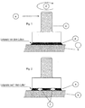
- the invention relates to the optimum shaping of connecting elements [ Fig. 1 ], which are soldered by means of a solder paste [a] on a metallic substrate [b].
- Such fasteners are usually designed as screw [c] or connectors.
- screw connections these are predominantly loaded with a torque [d], in the case of plug connections, however, usually with a tilting moment [e].
- the load capacity depends directly on the quality of the solder joint, ie on the adhesion of the connecting element on the substrate.
- soldering Another difficulty of soldering is that these connecting elements have a relatively large mass, therefore, the thermal energy expenditure for melting the solder paste is relatively high. If the solder joint is not supplied with sufficient thermal energy, so-called cold solder joints are formed which greatly reduce the adhesion of the connector to the substrate.
- an SMD component which is soldered by means of solder paste on a printed circuit board.
- the SMD component in this case comprises a foot portion and a tapered portion adjacent thereto with a smaller cross section, wherein the foot portion has a surface facing the substrate, which is soldered by means of the solder paste on the metallic substrate.
- a pressfit component with a foot section known from the display.
- SMD components are in the US 6,623,283 B1 or the DE 10 2012 021 323 A1 disclosed.
- a fundamental disadvantage of the known SMD components is that the mechanical load capacity of the solder joint is severely limited, especially in a torsional load.
- the aim of the present invention is to improve the adhesion and thus the mechanical strength of the soldered connection element in that the wettable surface is increased by appropriate shaping with the same base area and / or anchors are attached to the connecting element or on the substrate to the mechanical strength to increase.
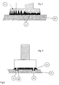
- the desired enlargement of the solderable surface is achieved by providing vertical grooves [k] on the periphery of the connecting element associated with the soldering surface.
- the molten solder rises [I] on the flanks of the grooves [k], [h] and on the walls of the holes, thereby additionally increasing the effectively soldered surface and thus improving the adhesion of the connecting elements to the substrate [b] becomes.
- grooves [h] and / or bores [i] on the solder side of the connecting element and / or on the substrate, it can additionally be achieved that the flux gases are collected and discharged to the outside, therefore no more disruptive gas bubbles can form, which would reduce the soldered surface.
Landscapes
- Coupling Device And Connection With Printed Circuit (AREA)
- Electric Connection Of Electric Components To Printed Circuits (AREA)
Description
- Die Erfindung bezieht sich auf die optimale Formgebung von Verbindungselementen [
Fig. 1 ], welche mittels einer Lotpaste [a] auf ein metallisches Substrat [b] gelötet werden. Solche Verbindungselemente werden üblicherweise als Schraub- [c] oder Steckverbindungen ausgeführt. Bei Schraubverbindungen werden diese vorwiegend mit einem Drehmoment [d], bei Steckverbindungen hingegen meist mit einem Kippmoment [e] belastet. Die Belastbarkeit hängt direkt von der Qualiät der Lötverbindung ab, also von der Haftung des Verbindungselements auf dem Substrat. - Die grundsätzliche Problematik bei Lötungen von großflächigen Teilen besteht darin, dass das in der Lotpaste enthaltene Flussmittel beim Lötvorgang Gase bildet, die in nur sehr geringem Maße seitlich und dies meist explosionsartig entweichen können. Der Großteil der Gase sammelt sich in Form von Gasblasen [
Fig.2 , f] zwischen dem metallischen Substrat und dem Verbindungselement. Diese Gasblasen bewirken, dass die gelötete Kontaktfläche reduziert und somit naturgemäß die Haftung des auf dem metallischen Substrat gelöteten Verbindungselements verringert wird. Folglich reduziert sich wiederum die mechanische Belastbarkeit in Bezug auf das maximal anwendbare Dreh- und Kippmoment. - Eine weitere Schwierigkeit der Lötung besteht darin, dass diese Verbindungselemente eine relativ große Masse besitzen, daher der thermische Energieaufwand zum Schmelzen der Lotpaste relativ hoch ist. Wenn die Lötstelle nicht mit ausreichend thermischer Energie versorgt wird, dann entstehen sogenannte kalte Lötstellen, welche die Haftung des Verbindungselements auf dem Substrat stark verringern.
- Aus der Anzeige "Broxing PowerClamps" in Elektronik Journal, 1. Mai 2011 (2011-05-01), Seite 78, XP055249711 ist ein SMD-Bauelement bekannt, das mittels Lotpaste auf eine Leiterplatte gelötet wird. Das SMD-Bauelement umfasst dabei einen Fußabschnitt sowie einen daran angrenzenden verjüngten Abschnitt mit einem kleineren Querschnitt, wobei der Fußabschnitt eine dem Substrat zugewandte Fläche aufweist, die mittels der Lotpaste auf das metallische Substrat gelötet wird. Darüber hinaus ist aus der Anzeige ein Pressfit-Bauteil mit einem Fußabschnitt bekannt.
- Ein grundsätzlicher Nachteil der bekannten SMD-Bauelemente besteht darin, dass die mechanische Belastbarkeit der Lötverbindung insbesondere bei einer Torsionsbelastung stark limitiert ist.
- Ziel der vorliegenden Erfindung ist es, die Haftung und somit die mechanische Belastbarkeit des gelöteten Verbindungselements dadurch zu verbessern, dass die benetzbare Oberfläche durch entsprechende Formgebung bei gleichbleibender Grundfläche vergrößert wird und/oder Verankerungen am Verbindungselement oder auf dem Substrat angebracht werden, um die mechanische Belastbarkeit zu erhöhen.
- Gemäß der Erfindung wird die gewünschte Vergrößerung der lötbaren Oberfläche dadurch erreicht, dass an dem der Lötfläche zugeordneten Umfang des Verbindungselements vertikale Rillen [k] angebracht werden.
- Beim Lötprozess steigt an den Flanken der Rillen [k],[h] und an den Wandungen der Bohrungen das geschmolzene Lötmittel hoch [I], wodurch sich die effektiv gelötete Oberfläche zusätzlich erhöht und somit die Haftung der Verbindungselemente auf dem Substrat [b] verbessert wird.
- Durch Anbringung von Rillen [h] und/oder Bohrungen [i] auf der Lötseite des Verbindungselements und/oder auf dem Substrat, kann zusätzlich erreicht werden, dass die Flussmittelgase gesammelt und nach außen abgeleitet werden, sich daher keine störenden Gasblasen mehr bilden können, welche die gelötete Oberfläche verringern würden.
- Die zusätzliche Anbringung von Verankerungen [m], die im gleichen Lötprozess von der Lotpaste [a1] benetzt werden, bewirkt, dass die mechanische Belastbarkeit weiter um ein Vielfaches erhöht wird. Diese Verankerungen [m] können sowohl am Verbindungselement [
Fig. 5 ] als auch am Substrat [b] angebracht werden und reichen in entsprechende Vertiefungen des Substrats [o] und/oder des Verbindungselements selbst. - In den
Fig. 1 und 2 bedeuten:- [a]
- Lotpaste
- [b]
- metallisches Substrat
- [c]
- Schraubverbindung
- [d]
- Drehmoment
- [e]
- Kippmament
- [f]
- Gasblasen
- In
Fig. 3 bedeutet:- [g]
- Massereduzierung durch Verjüngung
- [h]
- Rillen auf der Lötseite des Verbindungselements
- [i]
- Bohrungen auf der Lötseite des Verbindungselements
- [k]
- Rillen am Umfang des Verbindungselements
- In
Fig.4 bedeutet:- [b]
- Metallisches Substrat
- [k]
- Rillen am Umfang des Verbindungselements
- [l]
- hochgestiegenes Lötmittel
- In
Fig.5 bedeutet:- [a]
- Lötmittel zwischen Verbindungselement und Substrat
- [a1]
- Lötmittel auf der Verankerung
- [m]
- Verankerung
- [o]
- Vertiefung im Substrat
Claims (4)
- Verbindungselement (c), welches mittels einer Lotpaste (a) auf ein metallisches Substrat (b) gelötet wird, umfassend einen Fußabschnitt, der eine dem Substrat (b) zugewandte Fläche aufweist, die mittels der Lotpaste (a) auf das metallische Substrat (b) gelötet wird, dadurch gekennzeichnet, dass es an einer seitlichen Umfangsfläche mit Rillen (k) versehen ist, die in einer Längsrichtung des Verbindungselements (c) verlaufen und bis an den Rand der dem Substrat (b) zugewandten Fläche heran reichen, so dass die geschmolzene Lotpaste (a) an diesen hochsteigen kann und folglich die Haftung des Verbindungselements (c) auf dem Substrat (b) vergrößert wird.
- Verbindungselement (c) nach Anspruch 1, dadurch gekennzeichnet, dass es Verankerungen (m) aufweist, die dazu ausgelegt sind, in Öffnungen des Substrats (b) eingesetzt zu werden.
- Verbindungselement (c) nach Anspruch 2, dadurch gekennzeichnet, dass die Verankerungen (m) so dimensioniert sind, dass sie im eingesetzten Zustand kürzer sind als die Dicke des Substrats (b).
- Verbindungselement (c) nach einem der vorhergehenden Ansprüche, dadurch gekennzeichnet, dass es ein Gewinde oder eine Steckverbindung umfasst.
Priority Applications (2)
| Application Number | Priority Date | Filing Date | Title |
|---|---|---|---|
| EP15002499.0A EP3136510B1 (de) | 2015-08-24 | 2015-08-24 | Verbesserung der haftung von verbindungselementen die mittels lotpaste auf ein metallisches substrat gelötet werden |
| DE202015107004.7U DE202015107004U1 (de) | 2015-08-24 | 2015-12-22 | Verbesserung der Haftung von Verbindungselementen, die mittels einer Lotpaste auf ein metallisches Substrat gelötet werden |
Applications Claiming Priority (1)
| Application Number | Priority Date | Filing Date | Title |
|---|---|---|---|
| EP15002499.0A EP3136510B1 (de) | 2015-08-24 | 2015-08-24 | Verbesserung der haftung von verbindungselementen die mittels lotpaste auf ein metallisches substrat gelötet werden |
Publications (2)
| Publication Number | Publication Date |
|---|---|
| EP3136510A1 EP3136510A1 (de) | 2017-03-01 |
| EP3136510B1 true EP3136510B1 (de) | 2019-08-21 |
Family
ID=54011938
Family Applications (1)
| Application Number | Title | Priority Date | Filing Date |
|---|---|---|---|
| EP15002499.0A Active EP3136510B1 (de) | 2015-08-24 | 2015-08-24 | Verbesserung der haftung von verbindungselementen die mittels lotpaste auf ein metallisches substrat gelötet werden |
Country Status (2)
| Country | Link |
|---|---|
| EP (1) | EP3136510B1 (de) |
| DE (1) | DE202015107004U1 (de) |
Families Citing this family (1)
| Publication number | Priority date | Publication date | Assignee | Title |
|---|---|---|---|---|
| DE102019104318C5 (de) | 2019-02-20 | 2023-06-22 | Auto-Kabel Management Gmbh | Elektrischer Leiter sowie Verfahren zur Herstellung eines elektrischen Leiters |
Family Cites Families (3)
| Publication number | Priority date | Publication date | Assignee | Title |
|---|---|---|---|---|
| US6623283B1 (en) * | 2000-03-08 | 2003-09-23 | Autosplice, Inc. | Connector with base having channels to facilitate surface mount solder attachment |
| EP1720387A1 (de) * | 2005-05-03 | 2006-11-08 | Franz Broch | Hochstromkontakt in massiver Einpresstechnik |
| DE102012021323B4 (de) * | 2012-10-31 | 2020-12-10 | Mtconnectivity Power2Pcb Gmbh | Verfahren zur Herstellung eines elektrischen Anschlusselements |
-
2015
- 2015-08-24 EP EP15002499.0A patent/EP3136510B1/de active Active
- 2015-12-22 DE DE202015107004.7U patent/DE202015107004U1/de not_active Expired - Lifetime
Non-Patent Citations (1)
| Title |
|---|
| None * |
Also Published As
| Publication number | Publication date |
|---|---|
| DE202015107004U1 (de) | 2016-02-18 |
| EP3136510A1 (de) | 2017-03-01 |
Similar Documents
| Publication | Publication Date | Title |
|---|---|---|
| EP1268119B2 (de) | Verfahren zum herstellen eines schweissbolzens | |
| EP2489886A1 (de) | Beilagscheibe, Schraube oder Mutter mit erhöhtem Reibbeiwert | |
| AT516750B1 (de) | Verfahren zur Voidreduktion in Lötstellen | |
| EP0141195B1 (de) | Werkzeug | |
| EP1169736B1 (de) | Leistungshalbleitermodul | |
| DE112006000153T5 (de) | Befestigung für eine elektronische Komponente | |
| EP2543240A1 (de) | Elektrische kontaktanordnung | |
| EP2817120B1 (de) | Verfahren zum technologisch optimierten ausführen von lötverbindungen | |
| DE112010005383B4 (de) | Halbleitervorrichtung | |
| DE102014109361A1 (de) | Bauteilanordnung mit einer Blindnietmutter | |
| EP2862426B1 (de) | Verfahren zur fertigung von drucksensoren | |
| DE10357789B4 (de) | Leistungs-Halbleitervorrichtung | |
| EP3136510A1 (de) | Verbesserung der haftung von verbindungselementen die mittels lotpaste auf ein metallisches substrat gelötet werden | |
| EP1801688B1 (de) | Computergehäuse | |
| DE102019133891A1 (de) | Funktionselement | |
| DE9215578U1 (de) | Kabelschuh bzw. Preßverbinder | |
| EP2160932B1 (de) | Zwangsführung eines verbindungsmaterials | |
| DE102010018228A1 (de) | Metallhybrid-Verbundgussteil | |
| DE19829354C1 (de) | Unterlegscheibe sowie Bauteilverbindung mit einer Unterlegscheibe | |
| CH681030A5 (de) | ||
| DE202012003926U1 (de) | Anordnung zum technologisch optimierten Ausführen von Lötverbindungen | |
| WO2023094229A1 (de) | Leiterplattenanordnung | |
| DE10130618B4 (de) | Verfahren zum Bestücken eines Trägers mit einem Bauteil und Vorrichtung zum Verbinden derselben | |
| DE8626486U1 (de) | Schmelzsicherung für die direkte Bestückung von Leiterplatten | |
| DE29803840U1 (de) | Leuchtdiode |
Legal Events
| Date | Code | Title | Description |
|---|---|---|---|
| PUAI | Public reference made under article 153(3) epc to a published international application that has entered the european phase |
Free format text: ORIGINAL CODE: 0009012 |
|
| STAA | Information on the status of an ep patent application or granted ep patent |
Free format text: STATUS: THE APPLICATION HAS BEEN PUBLISHED |
|
| AK | Designated contracting states |
Kind code of ref document: A1 Designated state(s): AL AT BE BG CH CY CZ DE DK EE ES FI FR GB GR HR HU IE IS IT LI LT LU LV MC MK MT NL NO PL PT RO RS SE SI SK SM TR |
|
| AX | Request for extension of the european patent |
Extension state: BA ME |
|
| STAA | Information on the status of an ep patent application or granted ep patent |
Free format text: STATUS: REQUEST FOR EXAMINATION WAS MADE |
|
| 17P | Request for examination filed |
Effective date: 20170809 |
|
| RBV | Designated contracting states (corrected) |
Designated state(s): AL AT BE BG CH CY CZ DE DK EE ES FI FR GB GR HR HU IE IS IT LI LT LU LV MC MK MT NL NO PL PT RO RS SE SI SK SM TR |
|
| STAA | Information on the status of an ep patent application or granted ep patent |
Free format text: STATUS: EXAMINATION IS IN PROGRESS |
|
| 17Q | First examination report despatched |
Effective date: 20171221 |
|
| GRAP | Despatch of communication of intention to grant a patent |
Free format text: ORIGINAL CODE: EPIDOSNIGR1 |
|
| STAA | Information on the status of an ep patent application or granted ep patent |
Free format text: STATUS: GRANT OF PATENT IS INTENDED |
|
| RIC1 | Information provided on ipc code assigned before grant |
Ipc: H01R 4/02 20060101AFI20190218BHEP Ipc: H01R 9/16 20060101ALI20190218BHEP |
|
| INTG | Intention to grant announced |
Effective date: 20190312 |
|
| GRAS | Grant fee paid |
Free format text: ORIGINAL CODE: EPIDOSNIGR3 |
|
| GRAA | (expected) grant |
Free format text: ORIGINAL CODE: 0009210 |
|
| STAA | Information on the status of an ep patent application or granted ep patent |
Free format text: STATUS: THE PATENT HAS BEEN GRANTED |
|
| AK | Designated contracting states |
Kind code of ref document: B1 Designated state(s): AL AT BE BG CH CY CZ DE DK EE ES FI FR GB GR HR HU IE IS IT LI LT LU LV MC MK MT NL NO PL PT RO RS SE SI SK SM TR |
|
| REG | Reference to a national code |
Ref country code: GB Ref legal event code: FG4D Free format text: NOT ENGLISH |
|
| REG | Reference to a national code |
Ref country code: CH Ref legal event code: EP |
|
| REG | Reference to a national code |
Ref country code: DE Ref legal event code: R096 Ref document number: 502015010022 Country of ref document: DE |
|
| REG | Reference to a national code |
Ref country code: AT Ref legal event code: REF Ref document number: 1170808 Country of ref document: AT Kind code of ref document: T Effective date: 20190915 |
|
| REG | Reference to a national code |
Ref country code: IE Ref legal event code: FG4D Free format text: LANGUAGE OF EP DOCUMENT: GERMAN |
|
| REG | Reference to a national code |
Ref country code: LT Ref legal event code: MG4D |
|
| REG | Reference to a national code |
Ref country code: NL Ref legal event code: MP Effective date: 20190821 |
|
| PG25 | Lapsed in a contracting state [announced via postgrant information from national office to epo] |
Ref country code: SE Free format text: LAPSE BECAUSE OF FAILURE TO SUBMIT A TRANSLATION OF THE DESCRIPTION OR TO PAY THE FEE WITHIN THE PRESCRIBED TIME-LIMIT Effective date: 20190821 Ref country code: NO Free format text: LAPSE BECAUSE OF FAILURE TO SUBMIT A TRANSLATION OF THE DESCRIPTION OR TO PAY THE FEE WITHIN THE PRESCRIBED TIME-LIMIT Effective date: 20191121 Ref country code: BG Free format text: LAPSE BECAUSE OF FAILURE TO SUBMIT A TRANSLATION OF THE DESCRIPTION OR TO PAY THE FEE WITHIN THE PRESCRIBED TIME-LIMIT Effective date: 20191121 Ref country code: NL Free format text: LAPSE BECAUSE OF FAILURE TO SUBMIT A TRANSLATION OF THE DESCRIPTION OR TO PAY THE FEE WITHIN THE PRESCRIBED TIME-LIMIT Effective date: 20190821 Ref country code: LT Free format text: LAPSE BECAUSE OF FAILURE TO SUBMIT A TRANSLATION OF THE DESCRIPTION OR TO PAY THE FEE WITHIN THE PRESCRIBED TIME-LIMIT Effective date: 20190821 Ref country code: FI Free format text: LAPSE BECAUSE OF FAILURE TO SUBMIT A TRANSLATION OF THE DESCRIPTION OR TO PAY THE FEE WITHIN THE PRESCRIBED TIME-LIMIT Effective date: 20190821 Ref country code: HR Free format text: LAPSE BECAUSE OF FAILURE TO SUBMIT A TRANSLATION OF THE DESCRIPTION OR TO PAY THE FEE WITHIN THE PRESCRIBED TIME-LIMIT Effective date: 20190821 Ref country code: PT Free format text: LAPSE BECAUSE OF FAILURE TO SUBMIT A TRANSLATION OF THE DESCRIPTION OR TO PAY THE FEE WITHIN THE PRESCRIBED TIME-LIMIT Effective date: 20191223 |
|
| PG25 | Lapsed in a contracting state [announced via postgrant information from national office to epo] |
Ref country code: GR Free format text: LAPSE BECAUSE OF FAILURE TO SUBMIT A TRANSLATION OF THE DESCRIPTION OR TO PAY THE FEE WITHIN THE PRESCRIBED TIME-LIMIT Effective date: 20191122 Ref country code: ES Free format text: LAPSE BECAUSE OF FAILURE TO SUBMIT A TRANSLATION OF THE DESCRIPTION OR TO PAY THE FEE WITHIN THE PRESCRIBED TIME-LIMIT Effective date: 20190821 Ref country code: AL Free format text: LAPSE BECAUSE OF FAILURE TO SUBMIT A TRANSLATION OF THE DESCRIPTION OR TO PAY THE FEE WITHIN THE PRESCRIBED TIME-LIMIT Effective date: 20190821 Ref country code: LV Free format text: LAPSE BECAUSE OF FAILURE TO SUBMIT A TRANSLATION OF THE DESCRIPTION OR TO PAY THE FEE WITHIN THE PRESCRIBED TIME-LIMIT Effective date: 20190821 Ref country code: RS Free format text: LAPSE BECAUSE OF FAILURE TO SUBMIT A TRANSLATION OF THE DESCRIPTION OR TO PAY THE FEE WITHIN THE PRESCRIBED TIME-LIMIT Effective date: 20190821 Ref country code: IS Free format text: LAPSE BECAUSE OF FAILURE TO SUBMIT A TRANSLATION OF THE DESCRIPTION OR TO PAY THE FEE WITHIN THE PRESCRIBED TIME-LIMIT Effective date: 20191221 |
|
| PG25 | Lapsed in a contracting state [announced via postgrant information from national office to epo] |
Ref country code: TR Free format text: LAPSE BECAUSE OF FAILURE TO SUBMIT A TRANSLATION OF THE DESCRIPTION OR TO PAY THE FEE WITHIN THE PRESCRIBED TIME-LIMIT Effective date: 20190821 |
|
| PG25 | Lapsed in a contracting state [announced via postgrant information from national office to epo] |
Ref country code: DK Free format text: LAPSE BECAUSE OF FAILURE TO SUBMIT A TRANSLATION OF THE DESCRIPTION OR TO PAY THE FEE WITHIN THE PRESCRIBED TIME-LIMIT Effective date: 20190821 Ref country code: PL Free format text: LAPSE BECAUSE OF FAILURE TO SUBMIT A TRANSLATION OF THE DESCRIPTION OR TO PAY THE FEE WITHIN THE PRESCRIBED TIME-LIMIT Effective date: 20190821 Ref country code: EE Free format text: LAPSE BECAUSE OF FAILURE TO SUBMIT A TRANSLATION OF THE DESCRIPTION OR TO PAY THE FEE WITHIN THE PRESCRIBED TIME-LIMIT Effective date: 20190821 Ref country code: RO Free format text: LAPSE BECAUSE OF FAILURE TO SUBMIT A TRANSLATION OF THE DESCRIPTION OR TO PAY THE FEE WITHIN THE PRESCRIBED TIME-LIMIT Effective date: 20190821 |
|
| PG25 | Lapsed in a contracting state [announced via postgrant information from national office to epo] |
Ref country code: IS Free format text: LAPSE BECAUSE OF FAILURE TO SUBMIT A TRANSLATION OF THE DESCRIPTION OR TO PAY THE FEE WITHIN THE PRESCRIBED TIME-LIMIT Effective date: 20200224 Ref country code: MC Free format text: LAPSE BECAUSE OF FAILURE TO SUBMIT A TRANSLATION OF THE DESCRIPTION OR TO PAY THE FEE WITHIN THE PRESCRIBED TIME-LIMIT Effective date: 20190821 Ref country code: LU Free format text: LAPSE BECAUSE OF NON-PAYMENT OF DUE FEES Effective date: 20190824 Ref country code: SK Free format text: LAPSE BECAUSE OF FAILURE TO SUBMIT A TRANSLATION OF THE DESCRIPTION OR TO PAY THE FEE WITHIN THE PRESCRIBED TIME-LIMIT Effective date: 20190821 Ref country code: CZ Free format text: LAPSE BECAUSE OF FAILURE TO SUBMIT A TRANSLATION OF THE DESCRIPTION OR TO PAY THE FEE WITHIN THE PRESCRIBED TIME-LIMIT Effective date: 20190821 Ref country code: SM Free format text: LAPSE BECAUSE OF FAILURE TO SUBMIT A TRANSLATION OF THE DESCRIPTION OR TO PAY THE FEE WITHIN THE PRESCRIBED TIME-LIMIT Effective date: 20190821 |
|
| REG | Reference to a national code |
Ref country code: BE Ref legal event code: MM Effective date: 20190831 |
|
| REG | Reference to a national code |
Ref country code: DE Ref legal event code: R097 Ref document number: 502015010022 Country of ref document: DE |
|
| PLBE | No opposition filed within time limit |
Free format text: ORIGINAL CODE: 0009261 |
|
| STAA | Information on the status of an ep patent application or granted ep patent |
Free format text: STATUS: NO OPPOSITION FILED WITHIN TIME LIMIT |
|
| PG2D | Information on lapse in contracting state deleted |
Ref country code: IS |
|
| PG25 | Lapsed in a contracting state [announced via postgrant information from national office to epo] |
Ref country code: IE Free format text: LAPSE BECAUSE OF NON-PAYMENT OF DUE FEES Effective date: 20190824 |
|
| 26N | No opposition filed |
Effective date: 20200603 |
|
| PG25 | Lapsed in a contracting state [announced via postgrant information from national office to epo] |
Ref country code: BE Free format text: LAPSE BECAUSE OF NON-PAYMENT OF DUE FEES Effective date: 20190831 Ref country code: SI Free format text: LAPSE BECAUSE OF FAILURE TO SUBMIT A TRANSLATION OF THE DESCRIPTION OR TO PAY THE FEE WITHIN THE PRESCRIBED TIME-LIMIT Effective date: 20190821 |
|
| GBPC | Gb: european patent ceased through non-payment of renewal fee |
Effective date: 20191121 |
|
| PG25 | Lapsed in a contracting state [announced via postgrant information from national office to epo] |
Ref country code: GB Free format text: LAPSE BECAUSE OF NON-PAYMENT OF DUE FEES Effective date: 20191121 |
|
| PG25 | Lapsed in a contracting state [announced via postgrant information from national office to epo] |
Ref country code: CY Free format text: LAPSE BECAUSE OF FAILURE TO SUBMIT A TRANSLATION OF THE DESCRIPTION OR TO PAY THE FEE WITHIN THE PRESCRIBED TIME-LIMIT Effective date: 20190821 |
|
| PG25 | Lapsed in a contracting state [announced via postgrant information from national office to epo] |
Ref country code: MT Free format text: LAPSE BECAUSE OF FAILURE TO SUBMIT A TRANSLATION OF THE DESCRIPTION OR TO PAY THE FEE WITHIN THE PRESCRIBED TIME-LIMIT Effective date: 20190821 Ref country code: HU Free format text: LAPSE BECAUSE OF FAILURE TO SUBMIT A TRANSLATION OF THE DESCRIPTION OR TO PAY THE FEE WITHIN THE PRESCRIBED TIME-LIMIT; INVALID AB INITIO Effective date: 20150824 |
|
| PG25 | Lapsed in a contracting state [announced via postgrant information from national office to epo] |
Ref country code: MK Free format text: LAPSE BECAUSE OF FAILURE TO SUBMIT A TRANSLATION OF THE DESCRIPTION OR TO PAY THE FEE WITHIN THE PRESCRIBED TIME-LIMIT Effective date: 20190821 |
|
| PGFP | Annual fee paid to national office [announced via postgrant information from national office to epo] |
Ref country code: DE Payment date: 20250819 Year of fee payment: 11 |
|
| PGFP | Annual fee paid to national office [announced via postgrant information from national office to epo] |
Ref country code: IT Payment date: 20250829 Year of fee payment: 11 |
|
| PGFP | Annual fee paid to national office [announced via postgrant information from national office to epo] |
Ref country code: FR Payment date: 20250821 Year of fee payment: 11 Ref country code: AT Payment date: 20250819 Year of fee payment: 11 |
|
| PGFP | Annual fee paid to national office [announced via postgrant information from national office to epo] |
Ref country code: CH Payment date: 20250901 Year of fee payment: 11 |