EP3136524A1 - Chaine d'écrous de mise à la terre - Google Patents
Chaine d'écrous de mise à la terre Download PDFInfo
- Publication number
- EP3136524A1 EP3136524A1 EP16186057.2A EP16186057A EP3136524A1 EP 3136524 A1 EP3136524 A1 EP 3136524A1 EP 16186057 A EP16186057 A EP 16186057A EP 3136524 A1 EP3136524 A1 EP 3136524A1
- Authority
- EP
- European Patent Office
- Prior art keywords
- nuts
- grounding
- leg
- connecting element
- nut chain
- Prior art date
- Legal status (The legal status is an assumption and is not a legal conclusion. Google has not performed a legal analysis and makes no representation as to the accuracy of the status listed.)
- Granted
Links
Images


Classifications
-
- H—ELECTRICITY
- H02—GENERATION; CONVERSION OR DISTRIBUTION OF ELECTRIC POWER
- H02B—BOARDS, SUBSTATIONS OR SWITCHING ARRANGEMENTS FOR THE SUPPLY OR DISTRIBUTION OF ELECTRIC POWER
- H02B1/00—Frameworks, boards, panels, desks, casings; Details of substations or switching arrangements
- H02B1/16—Earthing arrangements
-
- H—ELECTRICITY
- H01—ELECTRIC ELEMENTS
- H01R—ELECTRICALLY-CONDUCTIVE CONNECTIONS; STRUCTURAL ASSOCIATIONS OF A PLURALITY OF MUTUALLY-INSULATED ELECTRICAL CONNECTING ELEMENTS; COUPLING DEVICES; CURRENT COLLECTORS
- H01R4/00—Electrically-conductive connections between two or more conductive members in direct contact, i.e. touching one another; Means for effecting or maintaining such contact; Electrically-conductive connections having two or more spaced connecting locations for conductors and using contact members penetrating insulation
- H01R4/28—Clamped connections, spring connections
- H01R4/30—Clamped connections, spring connections utilising a screw or nut clamping member
- H01R4/302—Clamped connections, spring connections utilising a screw or nut clamping member having means for preventing loosening of screw or nut, e.g. vibration-proof connection
-
- H—ELECTRICITY
- H01—ELECTRIC ELEMENTS
- H01R—ELECTRICALLY-CONDUCTIVE CONNECTIONS; STRUCTURAL ASSOCIATIONS OF A PLURALITY OF MUTUALLY-INSULATED ELECTRICAL CONNECTING ELEMENTS; COUPLING DEVICES; CURRENT COLLECTORS
- H01R31/00—Coupling parts supported only by co-operation with counterpart
- H01R31/08—Short-circuiting members for bridging contacts in a counterpart
- H01R31/085—Short circuiting bus-strips
-
- H—ELECTRICITY
- H01—ELECTRIC ELEMENTS
- H01R—ELECTRICALLY-CONDUCTIVE CONNECTIONS; STRUCTURAL ASSOCIATIONS OF A PLURALITY OF MUTUALLY-INSULATED ELECTRICAL CONNECTING ELEMENTS; COUPLING DEVICES; CURRENT COLLECTORS
- H01R4/00—Electrically-conductive connections between two or more conductive members in direct contact, i.e. touching one another; Means for effecting or maintaining such contact; Electrically-conductive connections having two or more spaced connecting locations for conductors and using contact members penetrating insulation
- H01R4/58—Electrically-conductive connections between two or more conductive members in direct contact, i.e. touching one another; Means for effecting or maintaining such contact; Electrically-conductive connections having two or more spaced connecting locations for conductors and using contact members penetrating insulation characterised by the form or material of the contacting members
- H01R4/64—Connections between or with conductive parts having primarily a non-electric function, e.g. frame, casing, rail
-
- H—ELECTRICITY
- H02—GENERATION; CONVERSION OR DISTRIBUTION OF ELECTRIC POWER
- H02B—BOARDS, SUBSTATIONS OR SWITCHING ARRANGEMENTS FOR THE SUPPLY OR DISTRIBUTION OF ELECTRIC POWER
- H02B1/00—Frameworks, boards, panels, desks, casings; Details of substations or switching arrangements
- H02B1/26—Casings; Parts thereof or accessories therefor
- H02B1/30—Cabinet-type casings; Parts thereof or accessories therefor
Definitions
- the invention relates to a grounding nut chain for arrangement on a control cabinet, a perforated plate, a perforated profile or the like.
- control cabinets usually have a plurality of mutually spaced recesses in suitable mounting plates for mounting electrical components.
- electrical or electronic components When mounting the electrical or electronic components in the control cabinet, it is common practice to make an electrically conductive connection between the components and the control cabinet housing in order to allow sufficient grounding of the electrical or electronic components.
- the grounding nuts have in the installed position in the direction of the control cabinet housing aligned blades or the like, which cut the paint layer of the control cabinet housing during assembly of the grounding nuts until the blades abut the electrically conductive sheet metal of the control cabinet.
- the blades or similar elements for cutting or removing the lacquer layer are also designed to be electrically conductive, so that via the blade and the grounding nut electrically connected to the blade an electrically conductive connection with any electrical or electronic components can be made by the For example, mother is connected via a cable connection with the respective electrical or electronic component.
- the cable can be fixed, for example by means of a suitable cable lug with the screw on the mother.
- a Erdungsmutternkette for placement on a cabinet, a perforated plate or the like, the Erdungsmutternkette having a plurality of nuts, wherein the nuts are spaced from each other, each adjacently arranged nuts are connected to each other via a connecting element and a distance between the nuts is adapted to each other to a hole spacing of recesses of the cabinet, the perforated plate or the like, so that the nuts of the grounding nut chain can be arranged on the recesses.
- a plurality of grounding nuts can be arranged on corresponding recesses of the cabinet in an assembly step.
- the connecting elements of the grounding nut chain are advantageously made rigid, so that the mounting of the grounding nut chain on adjacent recesses is further simplified.
- the nuts are rigidly connected to the connecting elements.
- the nuts are arranged displaceably on the connecting elements, so that the distance between the nuts to each other Hole spacing of the recesses can be adjusted.
- the grounding nut chain can be used for a variety of different cabinets and the like and the distance of the nuts to the respective hole spacing can be easily adjusted.
- At least one connecting element has a severing device, wherein the grounding nut chain can be separated with the aid of the severing device.
- individual connecting elements of the grounding nut chain have weakening areas, by which predetermined breaking points are formed, wherein the corresponding connecting element can be separated in the region of this predetermined breaking point by a suitable bending movement of the grounding nut chain.
- the invention provides that the connecting element has a holding leg, so that the connecting element can be arranged by clamping on a mounting portion of the cabinet, the perforated plate or the like.
- the connecting elements with the retaining legs can be easily pushed or pushed over a strip-shaped portion of the cabinet or the like, in which the recesses are arranged and can be fixed non-positively on this strip-shaped portion.
- the invention provides that the retaining leg has a clamping part.
- the clamping part is supported in the installed position against the cabinet housing or the strip-shaped section and causes an elastic deformation of the holding leg or the connecting element, by which a sufficient restoring force is caused to hold the grounding nut chain securely to the cabinet.
- the connecting element is U-shaped profile, wherein the nuts are arranged on a holding leg opposite side of the connecting element to the connecting element.
- the mother of the opposite side of the connecting element thus forms the holding leg.
- the connecting element is designed S-profile-shaped, wherein the holding leg merges into a plant leg, wherein the mounting portion between the plant leg and the holding leg can be clamped, the plant leg merges into a receiving leg and the nuts between the receiving leg and the plant leg are arranged.
- the legs of the U-shaped or S-shaped connecting element configured and connected to each other, that the legs can be pivoted relative to each other elastically, so that the connecting element are pushed onto the strip-shaped portion and can be fixed there by clamping and the nuts easily can be arranged between the holding leg and the plant leg.
- Erdungsmutternkette is provided that recesses are provided in the receiving leg, the nuts can be fixed in each case by clamping between an edge of the respective recess and the plant leg.
- the nuts When using the S-shaped profile designed connecting element, for example, defective nuts can be easily replaced by the receiving leg easily bent and the clamping between the receiving leg and the plant leg arranged nuts are removed. Also according to the invention provided that the nuts has a matched to a circumference of the recesses of the receiving leg head portion and an over the head portion laterally projecting abutment portion, wherein the head portion can be arranged in the recess and the abutment portion rests against the edge of the recess. In this way, the nuts can be positively and positively fixed to the connecting element. The nuts can be determined against rotation on the connecting element in this way without additional design effort or assembly effort to facilitate the insertion of a fastening screw.
- the connecting element is made in one piece.
- the connecting element can be produced from a bleaching strip by folding and punching.
- At least one leg end of the U- or S-shaped profile designed connecting element is designed angled outward.
- the holding leg can be easily raised by hand or with a suitable tool and released again from the strip-shaped section.
- the invention provides that a plurality of connecting elements are connected to each other and form a connecting element strip. In this way, nearly any length of grounding nut chains can be provided.
- the nuts each have at least one grounding part to produce electrically conductive connections to the control cabinet, the perforated plate, the hole profile or the like.
- the grounding part can be suitable blades, claws or the like, with which the lacquer layer of the housing can be severed or removed.
- the connecting elements each have at least one grounding part.
- a plurality of nuts can be connected simultaneously via the connecting element and arranged on the connecting element grounding member electrically conductively connected to the control cabinet housing.
- the connecting element, the nuts and the grounding part are advantageously made electrically conductive and electrically conductively connected to each other.
- the grounding nut chain is made of a suitable, electrically conductive metal.
- the grounding part can be formed by the clamping part.
- the clamping part is additionally designed so that the clamping part the Paint layer of the cabinet or the like cuts through or partially removed and so the grounding is made.
- the clamping part is advantageously made of an electrically conductive material and electrically conductively connected to the mother.
- the protruding sections of the grounding part are designed to protrude inwards and a protruding end portion of the grounding member is directed outward, and that the end portion of the grounding member can be displaced outwardly in a determination of a component on the grounding nut chain outward.
- a grounding part for example, designed arcuate and initially directed inward.
- a sharp-edged end portion of the grounding part is directed outwards again, but is still arranged completely in an interior surrounded by profile limbs.
- a grounding nut chain 1 is shown, which can be arranged on a strip-shaped portion 2 of a partially illustrated cabinet 3.
- the grounding nut chain 1 has a plurality of nuts 4 spaced from each other Connecting elements 5 are arranged. A distance between the nuts 4 to each other is adapted to a distance of recesses 6, which are provided in the strip-shaped portion 2 of the cabinet 3.
- the grounding nut chain 1 can be permanently fixed in the nuts 4 of the grounding nut chain 1 to the recesses 6 of the strip-shaped section 2 of the control cabinet 3 by arranging suitable screws, not shown, and electrically connected to the control cabinet 3.
- connection elements 5 of the grounding nut chain 1 are connected to each other and form a connecting element strip 7.
- Individual connecting elements 8 of the connecting element strip 7 have separating devices 9 in order to be able to separate the grounding nut chain 1.
- the separation devices 9 are formed by weakening areas, which each represent predetermined breaking points, so that the grounding nut chain 1 can be separated by a suitable bending movement in the area of the separating devices 9.
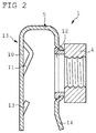
- Fig. 2 shows a schematically illustrated sectional view of the in Fig. 1 1.
- the connecting elements 5 of the grounding nut chain 1 are configured U-profile-shaped and each have a holding leg 10 with a clamping part 11.
- the nuts 4 are each arranged on a holding leg 10 opposite leg 12 of the connecting element 5. Laying down the nuts 4, these have an axially projecting mounting collar and are with riveted this mounting collar in a recess adapted thereto of the leg 12.
- the perforated plate or the like At the holding legs 10 of the connecting elements 5 are respectively Erdungskrallen 13 for producing the electrically conductive connection to the cabinet, the perforated plate or the like arranged so that a sharp-edged end portion of the grounding claws 13 inward, or to the opposite leg 12 and the nuts fixed thereto 4 is directed.
- the grounding claws 13 intersect the varnish of the cabinet, the perforated plate or the like when the grounding nut chain 1 is tightened by means of screws to the cabinet, the perforated plate or the like.
- the bow-shaped clamping member 11 also has a sharp-edged end portion.
- the holding leg 10 and the leg 12 are compressed and pressed the end portion of the inwardly directed clamping member 11 through a corresponding recess in the holding leg 10 outwardly in the direction of there abutting surface component.
- the end portion of the clamping part 11 then forms another grounding part 13.
- One leg end 14 of the leg 12 of the connecting element 5 is angled outwardly to facilitate the assembly of the grounding nut chain.
- FIGS. 3 to 5 Figures 8 and 9 are various views of a grounding nut chain 1 with a connector strip 7 of several S-shaped profile designed connecting elements 5 shown schematically.
- the S-profile-shaped connecting elements 5 each have a retaining leg 10, which merges into a contact leg 15.
- the connecting elements 5 each have a receiving leg 16, which also merges into the plant leg 15.
- an unillustrated attachment portion of a cabinet or the like can be determined by clamping.
- the nuts 4 each have a matched to a circumference 18 of the recesses 17 head portion 19 and a laterally projecting beyond the head portion 19 bearing portion 20.
- a length of the recesses 17 directed in a direction of extent of the grounding nut chain 1 is adapted to a length of the head sections 19, so that the nuts 4 rest flat against the recess 17 along these side edges.
- the recesses 17 have a width directed transversely to the extension direction of the grounding nut chain 1, which is slightly larger than a width of the head portions 19 of the nuts 4, so that the nuts 4 have a certain clearance in a direction transverse to the extending direction of the grounding nut chain 1 to be able to compensate for the occurring during assembly tolerances in the determination of the nuts 4.
- the nuts 4 are arranged between the respective bearing limb 15 and the associated receiving leg 16, that the head portion 19 is arranged in each case in the associated recess 17 and the abutment portion 20 rests against an edge 21 of the recess 17.
- grounding parts 13 and the clamping parts 11 are formed on the outwardly arched holding leg 10 and in each case projecting inwards, or directed to the opposite plant leg 15. In this way it can be achieved that the sharp-edged end portions of the grounding parts 13 and the clamping parts 11 are not accessible from the outside during handling and assembly of the grounding nut chain 1 and therefore do not form any appreciable risk of injury.
Landscapes
- Engineering & Computer Science (AREA)
- Power Engineering (AREA)
- Clamps And Clips (AREA)
- Elimination Of Static Electricity (AREA)
Applications Claiming Priority (1)
| Application Number | Priority Date | Filing Date | Title |
|---|---|---|---|
| DE102015114422.0A DE102015114422A1 (de) | 2015-08-28 | 2015-08-28 | Erdungsmutternkette |
Publications (2)
| Publication Number | Publication Date |
|---|---|
| EP3136524A1 true EP3136524A1 (fr) | 2017-03-01 |
| EP3136524B1 EP3136524B1 (fr) | 2020-03-04 |
Family
ID=56893705
Family Applications (1)
| Application Number | Title | Priority Date | Filing Date |
|---|---|---|---|
| EP16186057.2A Active EP3136524B1 (fr) | 2015-08-28 | 2016-08-26 | Chaine d'ecrous de mise a la terre |
Country Status (2)
| Country | Link |
|---|---|
| EP (1) | EP3136524B1 (fr) |
| DE (1) | DE102015114422A1 (fr) |
Cited By (2)
| Publication number | Priority date | Publication date | Assignee | Title |
|---|---|---|---|---|
| EP3540872A1 (fr) * | 2018-03-15 | 2019-09-18 | Wöhner Besitz GmbH | Barre omnibus hybride pour système de barres omnibus |
| CN113039677A (zh) * | 2018-11-12 | 2021-06-25 | 奇昊汽车德国有限责任公司 | 用于电动运行的车辆的电池壳体 |
Citations (4)
| Publication number | Priority date | Publication date | Assignee | Title |
|---|---|---|---|---|
| DE1540378A1 (de) * | 1964-03-13 | 1970-07-16 | Square D Co | Elektrische Schalttafel |
| US3832604A (en) * | 1973-04-09 | 1974-08-27 | Gen Electric | Electrical protective panel assembly |
| DE3437463A1 (de) * | 1984-10-12 | 1986-04-17 | R. Stahl Schaltgeräte GmbH, 7118 Künzelsau | Sammelschiene |
| DE29512907U1 (de) * | 1995-08-11 | 1995-10-19 | Hermann Kleinhuis GmbH & Co KG, 58507 Lüdenscheid | Potentialausgleichsschiene |
-
2015
- 2015-08-28 DE DE102015114422.0A patent/DE102015114422A1/de active Pending
-
2016
- 2016-08-26 EP EP16186057.2A patent/EP3136524B1/fr active Active
Patent Citations (4)
| Publication number | Priority date | Publication date | Assignee | Title |
|---|---|---|---|---|
| DE1540378A1 (de) * | 1964-03-13 | 1970-07-16 | Square D Co | Elektrische Schalttafel |
| US3832604A (en) * | 1973-04-09 | 1974-08-27 | Gen Electric | Electrical protective panel assembly |
| DE3437463A1 (de) * | 1984-10-12 | 1986-04-17 | R. Stahl Schaltgeräte GmbH, 7118 Künzelsau | Sammelschiene |
| DE29512907U1 (de) * | 1995-08-11 | 1995-10-19 | Hermann Kleinhuis GmbH & Co KG, 58507 Lüdenscheid | Potentialausgleichsschiene |
Cited By (8)
| Publication number | Priority date | Publication date | Assignee | Title |
|---|---|---|---|---|
| EP3540872A1 (fr) * | 2018-03-15 | 2019-09-18 | Wöhner Besitz GmbH | Barre omnibus hybride pour système de barres omnibus |
| WO2019175087A1 (fr) * | 2018-03-15 | 2019-09-19 | Woehner Besitz Gmbh | Barre omnibus hybride destinée à un système de barre omnibus |
| CN112005450A (zh) * | 2018-03-15 | 2020-11-27 | 维纳尔产业有限公司 | 用于汇流排系统的混合式汇流排 |
| US11139622B2 (en) | 2018-03-15 | 2021-10-05 | Woehner Besitz Gmbh | Hybrid busbar for a busbar system |
| CN112005450B (zh) * | 2018-03-15 | 2022-02-18 | 维纳尔产业有限公司 | 用于汇流排系统的混合式汇流排 |
| US11888272B2 (en) | 2018-03-15 | 2024-01-30 | Woehner Besitz Gmbh | Touch protected busbar system |
| CN113039677A (zh) * | 2018-11-12 | 2021-06-25 | 奇昊汽车德国有限责任公司 | 用于电动运行的车辆的电池壳体 |
| CN113039677B (zh) * | 2018-11-12 | 2023-04-25 | 奇昊汽车德国有限责任公司 | 用于电动运行的车辆的电池壳体 |
Also Published As
| Publication number | Publication date |
|---|---|
| EP3136524B1 (fr) | 2020-03-04 |
| DE102015114422A1 (de) | 2017-03-02 |
Similar Documents
| Publication | Publication Date | Title |
|---|---|---|
| EP2950395B1 (fr) | Couronne ressort pour un blindage de connecteurs électriques | |
| EP2915215B1 (fr) | Ensemble de modules en série pourvu d'un système de bus d'énergie | |
| EP3117112B1 (fr) | Système de fixation servant à monter des appareils, en particulier des appareils électriques | |
| DE10319086A1 (de) | Befestigungsvorrichtung | |
| DE10253858B4 (de) | Anschlußklemmelement und damit gebildete Anschlußklemme | |
| EP1068053A1 (fr) | Dispositif permettant d'enlever les parties a decortiquer d'une feuille de materiau ou equivalent | |
| EP2826114A1 (fr) | Unité de montage et procédé de montage d'un rail de montage sur une plaque de montage pour une armoire électrique | |
| EP3843221A1 (fr) | Cadre de support pour un connecteur | |
| EP3257121B1 (fr) | Ensemble de plusieurs pieds encliquetables pour module | |
| EP3563649B1 (fr) | Dispositif de fixation de composant | |
| EP2012390B1 (fr) | Pince de mise à la terre destinée à l'équilibrage du potentiel de canaux de câblage | |
| EP3026350B1 (fr) | Hotte aspirante dotée d'un composant | |
| EP3136524A1 (fr) | Chaine d'écrous de mise à la terre | |
| EP3071896B1 (fr) | Support de montage pour une enceinte et méthode de monter une enceinte utilisant ledit support | |
| DE102013101736A1 (de) | Anordnung zur Befestigung und Positionierung von Relais | |
| DE102015224595A1 (de) | Gedruckte-Leiterplatten-Einheit mit verbesserten Anschlüssen | |
| DE102024120727B3 (de) | Verschiebeschutz für ein Aufbaugerät auf einer Tragschiene | |
| EP0139980A2 (fr) | Cable clamp | |
| EP2339710A2 (fr) | Appareil d'installation électrique | |
| DE19539420A1 (de) | Schaltschrank | |
| DE202008007837U1 (de) | Anordnung zur Potentialanbindung gerahmter PV-Module | |
| EP1936765B1 (fr) | Appareil d'installation électrique/électronique | |
| EP2775225B1 (fr) | Système comprenant un cadre de support, un élément de filtre pouvant être fixé à l'intérieur et au moins deux dispositifs de fixation | |
| DE102012202633B4 (de) | Elektrischer Schalter, Kontaktelement, Schaltergehäuse sowie Verfahren zum elektrischen Kontaktieren | |
| DE102007016344B4 (de) | Haustechnikgerät mit einer Halteeinrichtung für eine Buchsenklemmleiste, Verfahren zur Montage einer Buchsenklemmleiste in ein Haustechnikgerät |
Legal Events
| Date | Code | Title | Description |
|---|---|---|---|
| PUAI | Public reference made under article 153(3) epc to a published international application that has entered the european phase |
Free format text: ORIGINAL CODE: 0009012 |
|
| STAA | Information on the status of an ep patent application or granted ep patent |
Free format text: STATUS: THE APPLICATION HAS BEEN PUBLISHED |
|
| AK | Designated contracting states |
Kind code of ref document: A1 Designated state(s): AL AT BE BG CH CY CZ DE DK EE ES FI FR GB GR HR HU IE IS IT LI LT LU LV MC MK MT NL NO PL PT RO RS SE SI SK SM TR |
|
| AX | Request for extension of the european patent |
Extension state: BA ME |
|
| STAA | Information on the status of an ep patent application or granted ep patent |
Free format text: STATUS: REQUEST FOR EXAMINATION WAS MADE |
|
| 17P | Request for examination filed |
Effective date: 20170830 |
|
| RBV | Designated contracting states (corrected) |
Designated state(s): AL AT BE BG CH CY CZ DE DK EE ES FI FR GB GR HR HU IE IS IT LI LT LU LV MC MK MT NL NO PL PT RO RS SE SI SK SM TR |
|
| STAA | Information on the status of an ep patent application or granted ep patent |
Free format text: STATUS: EXAMINATION IS IN PROGRESS |
|
| 17Q | First examination report despatched |
Effective date: 20171106 |
|
| GRAP | Despatch of communication of intention to grant a patent |
Free format text: ORIGINAL CODE: EPIDOSNIGR1 |
|
| STAA | Information on the status of an ep patent application or granted ep patent |
Free format text: STATUS: GRANT OF PATENT IS INTENDED |
|
| RIC1 | Information provided on ipc code assigned before grant |
Ipc: H02B 1/30 20060101ALN20190826BHEP Ipc: H01R 4/64 20060101ALN20190826BHEP Ipc: H01R 4/30 20060101ALI20190826BHEP Ipc: H01R 31/08 20060101ALN20190826BHEP Ipc: H02B 1/16 20060101AFI20190826BHEP |
|
| INTG | Intention to grant announced |
Effective date: 20190930 |
|
| GRAS | Grant fee paid |
Free format text: ORIGINAL CODE: EPIDOSNIGR3 |
|
| GRAA | (expected) grant |
Free format text: ORIGINAL CODE: 0009210 |
|
| STAA | Information on the status of an ep patent application or granted ep patent |
Free format text: STATUS: THE PATENT HAS BEEN GRANTED |
|
| AK | Designated contracting states |
Kind code of ref document: B1 Designated state(s): AL AT BE BG CH CY CZ DE DK EE ES FI FR GB GR HR HU IE IS IT LI LT LU LV MC MK MT NL NO PL PT RO RS SE SI SK SM TR |
|
| REG | Reference to a national code |
Ref country code: GB Ref legal event code: FG4D Free format text: NOT ENGLISH |
|
| REG | Reference to a national code |
Ref country code: CH Ref legal event code: EP |
|
| REG | Reference to a national code |
Ref country code: AT Ref legal event code: REF Ref document number: 1241474 Country of ref document: AT Kind code of ref document: T Effective date: 20200315 |
|
| REG | Reference to a national code |
Ref country code: DE Ref legal event code: R096 Ref document number: 502016009001 Country of ref document: DE |
|
| REG | Reference to a national code |
Ref country code: IE Ref legal event code: FG4D Free format text: LANGUAGE OF EP DOCUMENT: GERMAN |
|
| PG25 | Lapsed in a contracting state [announced via postgrant information from national office to epo] |
Ref country code: RS Free format text: LAPSE BECAUSE OF FAILURE TO SUBMIT A TRANSLATION OF THE DESCRIPTION OR TO PAY THE FEE WITHIN THE PRESCRIBED TIME-LIMIT Effective date: 20200304 Ref country code: FI Free format text: LAPSE BECAUSE OF FAILURE TO SUBMIT A TRANSLATION OF THE DESCRIPTION OR TO PAY THE FEE WITHIN THE PRESCRIBED TIME-LIMIT Effective date: 20200304 Ref country code: NO Free format text: LAPSE BECAUSE OF FAILURE TO SUBMIT A TRANSLATION OF THE DESCRIPTION OR TO PAY THE FEE WITHIN THE PRESCRIBED TIME-LIMIT Effective date: 20200604 |
|
| REG | Reference to a national code |
Ref country code: NL Ref legal event code: MP Effective date: 20200304 |
|
| PG25 | Lapsed in a contracting state [announced via postgrant information from national office to epo] |
Ref country code: LV Free format text: LAPSE BECAUSE OF FAILURE TO SUBMIT A TRANSLATION OF THE DESCRIPTION OR TO PAY THE FEE WITHIN THE PRESCRIBED TIME-LIMIT Effective date: 20200304 Ref country code: SE Free format text: LAPSE BECAUSE OF FAILURE TO SUBMIT A TRANSLATION OF THE DESCRIPTION OR TO PAY THE FEE WITHIN THE PRESCRIBED TIME-LIMIT Effective date: 20200304 Ref country code: BG Free format text: LAPSE BECAUSE OF FAILURE TO SUBMIT A TRANSLATION OF THE DESCRIPTION OR TO PAY THE FEE WITHIN THE PRESCRIBED TIME-LIMIT Effective date: 20200604 Ref country code: GR Free format text: LAPSE BECAUSE OF FAILURE TO SUBMIT A TRANSLATION OF THE DESCRIPTION OR TO PAY THE FEE WITHIN THE PRESCRIBED TIME-LIMIT Effective date: 20200605 Ref country code: HR Free format text: LAPSE BECAUSE OF FAILURE TO SUBMIT A TRANSLATION OF THE DESCRIPTION OR TO PAY THE FEE WITHIN THE PRESCRIBED TIME-LIMIT Effective date: 20200304 |
|
| REG | Reference to a national code |
Ref country code: LT Ref legal event code: MG4D |
|
| PG25 | Lapsed in a contracting state [announced via postgrant information from national office to epo] |
Ref country code: NL Free format text: LAPSE BECAUSE OF FAILURE TO SUBMIT A TRANSLATION OF THE DESCRIPTION OR TO PAY THE FEE WITHIN THE PRESCRIBED TIME-LIMIT Effective date: 20200304 |
|
| PG25 | Lapsed in a contracting state [announced via postgrant information from national office to epo] |
Ref country code: LT Free format text: LAPSE BECAUSE OF FAILURE TO SUBMIT A TRANSLATION OF THE DESCRIPTION OR TO PAY THE FEE WITHIN THE PRESCRIBED TIME-LIMIT Effective date: 20200304 Ref country code: EE Free format text: LAPSE BECAUSE OF FAILURE TO SUBMIT A TRANSLATION OF THE DESCRIPTION OR TO PAY THE FEE WITHIN THE PRESCRIBED TIME-LIMIT Effective date: 20200304 Ref country code: SK Free format text: LAPSE BECAUSE OF FAILURE TO SUBMIT A TRANSLATION OF THE DESCRIPTION OR TO PAY THE FEE WITHIN THE PRESCRIBED TIME-LIMIT Effective date: 20200304 Ref country code: IS Free format text: LAPSE BECAUSE OF FAILURE TO SUBMIT A TRANSLATION OF THE DESCRIPTION OR TO PAY THE FEE WITHIN THE PRESCRIBED TIME-LIMIT Effective date: 20200704 Ref country code: CZ Free format text: LAPSE BECAUSE OF FAILURE TO SUBMIT A TRANSLATION OF THE DESCRIPTION OR TO PAY THE FEE WITHIN THE PRESCRIBED TIME-LIMIT Effective date: 20200304 Ref country code: ES Free format text: LAPSE BECAUSE OF FAILURE TO SUBMIT A TRANSLATION OF THE DESCRIPTION OR TO PAY THE FEE WITHIN THE PRESCRIBED TIME-LIMIT Effective date: 20200304 Ref country code: RO Free format text: LAPSE BECAUSE OF FAILURE TO SUBMIT A TRANSLATION OF THE DESCRIPTION OR TO PAY THE FEE WITHIN THE PRESCRIBED TIME-LIMIT Effective date: 20200304 Ref country code: PT Free format text: LAPSE BECAUSE OF FAILURE TO SUBMIT A TRANSLATION OF THE DESCRIPTION OR TO PAY THE FEE WITHIN THE PRESCRIBED TIME-LIMIT Effective date: 20200729 Ref country code: SM Free format text: LAPSE BECAUSE OF FAILURE TO SUBMIT A TRANSLATION OF THE DESCRIPTION OR TO PAY THE FEE WITHIN THE PRESCRIBED TIME-LIMIT Effective date: 20200304 |
|
| REG | Reference to a national code |
Ref country code: DE Ref legal event code: R097 Ref document number: 502016009001 Country of ref document: DE |
|
| PLBE | No opposition filed within time limit |
Free format text: ORIGINAL CODE: 0009261 |
|
| STAA | Information on the status of an ep patent application or granted ep patent |
Free format text: STATUS: NO OPPOSITION FILED WITHIN TIME LIMIT |
|
| PG25 | Lapsed in a contracting state [announced via postgrant information from national office to epo] |
Ref country code: DK Free format text: LAPSE BECAUSE OF FAILURE TO SUBMIT A TRANSLATION OF THE DESCRIPTION OR TO PAY THE FEE WITHIN THE PRESCRIBED TIME-LIMIT Effective date: 20200304 Ref country code: IT Free format text: LAPSE BECAUSE OF FAILURE TO SUBMIT A TRANSLATION OF THE DESCRIPTION OR TO PAY THE FEE WITHIN THE PRESCRIBED TIME-LIMIT Effective date: 20200304 |
|
| 26N | No opposition filed |
Effective date: 20201207 |
|
| PG25 | Lapsed in a contracting state [announced via postgrant information from national office to epo] |
Ref country code: SI Free format text: LAPSE BECAUSE OF FAILURE TO SUBMIT A TRANSLATION OF THE DESCRIPTION OR TO PAY THE FEE WITHIN THE PRESCRIBED TIME-LIMIT Effective date: 20200304 Ref country code: PL Free format text: LAPSE BECAUSE OF FAILURE TO SUBMIT A TRANSLATION OF THE DESCRIPTION OR TO PAY THE FEE WITHIN THE PRESCRIBED TIME-LIMIT Effective date: 20200304 |
|
| PG25 | Lapsed in a contracting state [announced via postgrant information from national office to epo] |
Ref country code: MC Free format text: LAPSE BECAUSE OF FAILURE TO SUBMIT A TRANSLATION OF THE DESCRIPTION OR TO PAY THE FEE WITHIN THE PRESCRIBED TIME-LIMIT Effective date: 20200304 |
|
| REG | Reference to a national code |
Ref country code: CH Ref legal event code: PL |
|
| PG25 | Lapsed in a contracting state [announced via postgrant information from national office to epo] |
Ref country code: LI Free format text: LAPSE BECAUSE OF NON-PAYMENT OF DUE FEES Effective date: 20200831 Ref country code: LU Free format text: LAPSE BECAUSE OF NON-PAYMENT OF DUE FEES Effective date: 20200826 Ref country code: CH Free format text: LAPSE BECAUSE OF NON-PAYMENT OF DUE FEES Effective date: 20200831 |
|
| REG | Reference to a national code |
Ref country code: BE Ref legal event code: MM Effective date: 20200831 |
|
| PG25 | Lapsed in a contracting state [announced via postgrant information from national office to epo] |
Ref country code: BE Free format text: LAPSE BECAUSE OF NON-PAYMENT OF DUE FEES Effective date: 20200831 Ref country code: IE Free format text: LAPSE BECAUSE OF NON-PAYMENT OF DUE FEES Effective date: 20200826 |
|
| PG25 | Lapsed in a contracting state [announced via postgrant information from national office to epo] |
Ref country code: TR Free format text: LAPSE BECAUSE OF FAILURE TO SUBMIT A TRANSLATION OF THE DESCRIPTION OR TO PAY THE FEE WITHIN THE PRESCRIBED TIME-LIMIT Effective date: 20200304 Ref country code: MT Free format text: LAPSE BECAUSE OF FAILURE TO SUBMIT A TRANSLATION OF THE DESCRIPTION OR TO PAY THE FEE WITHIN THE PRESCRIBED TIME-LIMIT Effective date: 20200304 Ref country code: CY Free format text: LAPSE BECAUSE OF FAILURE TO SUBMIT A TRANSLATION OF THE DESCRIPTION OR TO PAY THE FEE WITHIN THE PRESCRIBED TIME-LIMIT Effective date: 20200304 |
|
| PG25 | Lapsed in a contracting state [announced via postgrant information from national office to epo] |
Ref country code: MK Free format text: LAPSE BECAUSE OF FAILURE TO SUBMIT A TRANSLATION OF THE DESCRIPTION OR TO PAY THE FEE WITHIN THE PRESCRIBED TIME-LIMIT Effective date: 20200304 Ref country code: AL Free format text: LAPSE BECAUSE OF FAILURE TO SUBMIT A TRANSLATION OF THE DESCRIPTION OR TO PAY THE FEE WITHIN THE PRESCRIBED TIME-LIMIT Effective date: 20200304 |
|
| REG | Reference to a national code |
Ref country code: AT Ref legal event code: MM01 Ref document number: 1241474 Country of ref document: AT Kind code of ref document: T Effective date: 20210826 |
|
| PG25 | Lapsed in a contracting state [announced via postgrant information from national office to epo] |
Ref country code: AT Free format text: LAPSE BECAUSE OF NON-PAYMENT OF DUE FEES Effective date: 20210826 |
|
| PGFP | Annual fee paid to national office [announced via postgrant information from national office to epo] |
Ref country code: DE Payment date: 20250825 Year of fee payment: 10 |
|
| PGFP | Annual fee paid to national office [announced via postgrant information from national office to epo] |
Ref country code: GB Payment date: 20250923 Year of fee payment: 10 |
|
| PGFP | Annual fee paid to national office [announced via postgrant information from national office to epo] |
Ref country code: FR Payment date: 20250828 Year of fee payment: 10 |