EP3136539A1 - Procede et dispositif de chargement de batteries - Google Patents
Procede et dispositif de chargement de batteries Download PDFInfo
- Publication number
- EP3136539A1 EP3136539A1 EP16190154.1A EP16190154A EP3136539A1 EP 3136539 A1 EP3136539 A1 EP 3136539A1 EP 16190154 A EP16190154 A EP 16190154A EP 3136539 A1 EP3136539 A1 EP 3136539A1
- Authority
- EP
- European Patent Office
- Prior art keywords
- charging
- battery
- voltage
- current
- charge
- Prior art date
- Legal status (The legal status is an assumption and is not a legal conclusion. Google has not performed a legal analysis and makes no representation as to the accuracy of the status listed.)
- Withdrawn
Links
Images




Classifications
-
- H—ELECTRICITY
- H01—ELECTRIC ELEMENTS
- H01M—PROCESSES OR MEANS, e.g. BATTERIES, FOR THE DIRECT CONVERSION OF CHEMICAL ENERGY INTO ELECTRICAL ENERGY
- H01M10/00—Secondary cells; Manufacture thereof
- H01M10/06—Lead-acid accumulators
-
- G—PHYSICS
- G01—MEASURING; TESTING
- G01R—MEASURING ELECTRIC VARIABLES; MEASURING MAGNETIC VARIABLES
- G01R31/00—Arrangements for testing electric properties; Arrangements for locating electric faults; Arrangements for electrical testing characterised by what is being tested not provided for elsewhere
- G01R31/36—Arrangements for testing, measuring or monitoring the electrical condition of accumulators or electric batteries, e.g. capacity or state of charge [SoC]
- G01R31/382—Arrangements for monitoring battery or accumulator variables, e.g. SoC
- G01R31/3835—Arrangements for monitoring battery or accumulator variables, e.g. SoC involving only voltage measurements
-
- G—PHYSICS
- G01—MEASURING; TESTING
- G01R—MEASURING ELECTRIC VARIABLES; MEASURING MAGNETIC VARIABLES
- G01R31/00—Arrangements for testing electric properties; Arrangements for locating electric faults; Arrangements for electrical testing characterised by what is being tested not provided for elsewhere
- G01R31/36—Arrangements for testing, measuring or monitoring the electrical condition of accumulators or electric batteries, e.g. capacity or state of charge [SoC]
- G01R31/385—Arrangements for measuring battery or accumulator variables
- G01R31/387—Determining ampere-hour charge capacity or SoC
- G01R31/388—Determining ampere-hour charge capacity or SoC involving voltage measurements
-
- H—ELECTRICITY
- H01—ELECTRIC ELEMENTS
- H01M—PROCESSES OR MEANS, e.g. BATTERIES, FOR THE DIRECT CONVERSION OF CHEMICAL ENERGY INTO ELECTRICAL ENERGY
- H01M10/00—Secondary cells; Manufacture thereof
- H01M10/42—Methods or arrangements for servicing or maintenance of secondary cells or secondary half-cells
- H01M10/44—Methods for charging or discharging
-
- H—ELECTRICITY
- H01—ELECTRIC ELEMENTS
- H01M—PROCESSES OR MEANS, e.g. BATTERIES, FOR THE DIRECT CONVERSION OF CHEMICAL ENERGY INTO ELECTRICAL ENERGY
- H01M10/00—Secondary cells; Manufacture thereof
- H01M10/42—Methods or arrangements for servicing or maintenance of secondary cells or secondary half-cells
- H01M10/44—Methods for charging or discharging
- H01M10/446—Initial charging measures
-
- H—ELECTRICITY
- H02—GENERATION; CONVERSION OR DISTRIBUTION OF ELECTRIC POWER
- H02J—ELECTRIC POWER NETWORKS; CIRCUIT ARRANGEMENTS OR SYSTEMS FOR SUPPLYING OR DISTRIBUTING ELECTRIC POWER; SYSTEMS FOR STORING ELECTRIC ENERGY
- H02J7/00—Circuit arrangements for charging or discharging batteries or for supplying loads from batteries
- H02J7/02—Circuit arrangements for charging or discharging batteries or for supplying loads from batteries for charging batteries from AC mains by converters
- H02J7/04—Regulation of charging current or voltage
-
- H—ELECTRICITY
- H02—GENERATION; CONVERSION OR DISTRIBUTION OF ELECTRIC POWER
- H02J—ELECTRIC POWER NETWORKS; CIRCUIT ARRANGEMENTS OR SYSTEMS FOR SUPPLYING OR DISTRIBUTING ELECTRIC POWER; SYSTEMS FOR STORING ELECTRIC ENERGY
- H02J7/00—Circuit arrangements for charging or discharging batteries or for supplying loads from batteries
- H02J7/90—Regulation of charging or discharging current or voltage
- H02J7/92—Regulation of charging or discharging current or voltage with prioritisation of loads or sources
-
- H—ELECTRICITY
- H02—GENERATION; CONVERSION OR DISTRIBUTION OF ELECTRIC POWER
- H02J—ELECTRIC POWER NETWORKS; CIRCUIT ARRANGEMENTS OR SYSTEMS FOR SUPPLYING OR DISTRIBUTING ELECTRIC POWER; SYSTEMS FOR STORING ELECTRIC ENERGY
- H02J7/00—Circuit arrangements for charging or discharging batteries or for supplying loads from batteries
- H02J7/90—Regulation of charging or discharging current or voltage
- H02J7/96—Regulation of charging or discharging current or voltage in response to battery voltage
-
- H—ELECTRICITY
- H02—GENERATION; CONVERSION OR DISTRIBUTION OF ELECTRIC POWER
- H02J—ELECTRIC POWER NETWORKS; CIRCUIT ARRANGEMENTS OR SYSTEMS FOR SUPPLYING OR DISTRIBUTING ELECTRIC POWER; SYSTEMS FOR STORING ELECTRIC ENERGY
- H02J7/00—Circuit arrangements for charging or discharging batteries or for supplying loads from batteries
- H02J7/90—Regulation of charging or discharging current or voltage
- H02J7/927—Regulation of charging or discharging current or voltage with introduction of pulses during the charging process
-
- Y—GENERAL TAGGING OF NEW TECHNOLOGICAL DEVELOPMENTS; GENERAL TAGGING OF CROSS-SECTIONAL TECHNOLOGIES SPANNING OVER SEVERAL SECTIONS OF THE IPC; TECHNICAL SUBJECTS COVERED BY FORMER USPC CROSS-REFERENCE ART COLLECTIONS [XRACs] AND DIGESTS
- Y02—TECHNOLOGIES OR APPLICATIONS FOR MITIGATION OR ADAPTATION AGAINST CLIMATE CHANGE
- Y02E—REDUCTION OF GREENHOUSE GAS [GHG] EMISSIONS, RELATED TO ENERGY GENERATION, TRANSMISSION OR DISTRIBUTION
- Y02E60/00—Enabling technologies; Technologies with a potential or indirect contribution to GHG emissions mitigation
- Y02E60/10—Energy storage using batteries
-
- Y—GENERAL TAGGING OF NEW TECHNOLOGICAL DEVELOPMENTS; GENERAL TAGGING OF CROSS-SECTIONAL TECHNOLOGIES SPANNING OVER SEVERAL SECTIONS OF THE IPC; TECHNICAL SUBJECTS COVERED BY FORMER USPC CROSS-REFERENCE ART COLLECTIONS [XRACs] AND DIGESTS
- Y02—TECHNOLOGIES OR APPLICATIONS FOR MITIGATION OR ADAPTATION AGAINST CLIMATE CHANGE
- Y02T—CLIMATE CHANGE MITIGATION TECHNOLOGIES RELATED TO TRANSPORTATION
- Y02T10/00—Road transport of goods or passengers
- Y02T10/60—Other road transportation technologies with climate change mitigation effect
- Y02T10/70—Energy storage systems for electromobility, e.g. batteries
Definitions
- the invention relates to a method and a device for charging batteries, in particular lead-acid batteries, with a predetermined charge end voltage, wherein prior to charging the state of charge of the battery is detected, and the battery is charged during the charging process with a charging current or a charging voltage ,
- the subject invention is suitable for charging a variety of rechargeable batteries, such as lead-acid batteries, lithium batteries, nickel-metal hydride (NiMH) batteries and many more.
- rechargeable batteries such as lead-acid batteries, lithium batteries, nickel-metal hydride (NiMH) batteries and many more.
- lead-acid batteries as used for example for electrically driven vehicles, the charging method according to the invention and the charging device according to the invention is because of the high dependence of the internal resistance of such batteries from the state of charge, however, particularly advantageous.
- Improvements can be made if the current charge voltage of the battery is considered during the charging process. For example, describe the WO 96/16460 A1 or the DE 10 2009 051 731 A1 Such battery charging methods and devices.
- the JP 2008-061373 A relates to a charging method and a charging device in which the battery is charged with a constant current.
- the EP 1 104 074 A1 describes a voltage limiting circuit which is arranged in parallel with a battery to achieve an improved charge thereof.
- the object of the present invention is therefore to provide a method and a device for charging a battery, in particular lead-acid battery, by which the efficiency of the charge and thus the efficiency can be increased and the life of the battery can be extended. Especially should be provided with sufficient charging time optimal charge of the battery. Disadvantages of known charging systems should be prevented or at least reduced.
- the object of the invention is achieved by an above-mentioned method for charging a battery, wherein the charging voltage during a predetermined charging time by impressed current pulses or voltage pulses between a charge starting voltage according to the state of charge of the battery and the end-of-charge voltage is gradually increased, and in the intervals between two current pulses or and voltage pulses, the internal resistance of the battery is measured, and the charging current or the charging voltage is controlled so that the charging current or the charging voltage is adjusted to the measured internal resistance .. Before the actual charging so the current state of charge of the battery is determined and then the charging current or the charging voltage adapted to this state of charge of the battery and the set or predetermined charging time.
- the method according to the invention takes account of the actual state of charge of the battery and the possible charging time and adapts the charge accordingly to these two parameters. Characterized in that the increase of the charging voltage between the charging start voltage and the charging voltage of the battery during the charging time by appropriate control of the charging current or the charging voltage is taken indirectly on the current internal resistance of the battery consideration. Thus, a gentle charge of the battery under optimal utilization of the available charging time. As a result, there is only a minimal heating of the battery and thus a minimization of aging, whereby the life of the battery can be increased. By the method according to the invention increases in the charging efficiency in the range between 5 and 15% can be achieved. The process is relatively easy to implement.
- the charge start voltage may correspond to the open circuit voltage of the battery or to a voltage that the battery has after undergoing a process before performing the charging process, For example, a depolarization has gone through.
- the charging current or the charging voltage is regulated such that the charging voltage is increased linearly during the charging time between the charging start voltage and the charging end voltage. This allows a simple realization of the charging method by generating a ramp of the charging voltage between the charging start voltage and the charging end voltage over the predetermined charging time.
- the slope of the voltage ramp is reduced, but still essentially utilizes the full charge time.
- the fact that the voltage ramp is realized by appropriate control of the charging current or the charging voltage, there is also an automatic adjustment to the respective internal resistance of the battery. Deviations from the linear progression of the charging voltage can be advantageous for certain applications and possibly further increase efficiency.
- the control can also provide that the voltage ramp is divided into a plurality of partial ramps with different pitch, for example, to compensate for the occurrence of too high a charging current in the phase of the minimum internal resistance of the battery.
- the actual state of the battery can be better considered and the charge can be made with optimum efficiency.
- the charging process can be effected both by impressed current pulses and by impressed voltage pulses, wherein the resulting charging voltage is increased during the predetermined charging time between the charging starting voltage in accordance with the state of charge of the battery and the charging end voltage. In the pulse pauses, the internal resistance of the battery is measured. When impressing current pulses, this can be done by measuring the voltage response that results in reducing the current value to a predetermined value or zero.
- a message is issued when the charging current necessary to achieve the charging voltage during the charging time is above a maximum possible charging current. If the charging current is insufficient for the specified charging time, the battery would not be fully charged during this charging time can be. By the message the user can take care of it and for example increase the loading time accordingly.
- the state of charge of the battery can be determined in the simplest case by measuring the current open circuit voltage.
- the current open circuit voltage may then be used as a charge start voltage, or methods may be used which prepare the battery for charging (eg, a depolarization method) and then use the resulting voltage of the battery as the charge start voltage.
- a depolarization method e.g., a depolarization method
- this can also be carried out via acid density determination, ampere-hour balancing or impedance measurement.
- Advantages can be achieved when the battery is depolarized prior to charging when the open circuit voltage is below a predetermined threshold by controlling the charging current or voltage to produce a voltage ramp between the open circuit voltage of the battery and a defined depolarization voltage.
- Such a depolarization can bring a "shifted" electrode potential of a battery back into equilibrium.
- the voltage of the battery resulting after the depolarization process then corresponds to the charge starting voltage of the charging process.
- the depolarization voltage ramp can be repeated at least once.
- the duration of the depolarization process is chosen as a fraction of the total available charging time. For example, the duration of the depolarization can be selected within a few minutes with a charging time of a few hours.
- a recharge can be carried out to fully charge the battery.
- various common methods can be used.
- the desired time at which the battery is to be fully charged can also be entered or specified, and the charging time can be determined as the difference between this predetermined end time of the charging process and the current time. This facilitates the handling of the charger, since the user no longer has to calculate the available charging time, but merely has to specify when he needs the fully charged battery. In particular, in a shift operation, such a possibility is advantageous.
- the predetermined charging time can be reduced to a fraction, in particular to 50% to 90% of the specified charging time, in order to still have sufficient time for the possible depolarization process or other procedures. It is also ensured by such a shortening of the definitive charging time that the battery is already fully charged before the agreed time and, for example, can be installed in a truck in good time before a start of shift.
- a maximum possible time interval for the delay of the charging process can be proposed and displayed.
- the user can be offered, for example, the possibility of using cheaper nighttime electricity.
- the driver then has to adjust the delay by actuating the battery charger accordingly.
- control device is designed to control the charging current or the charging voltage, the control device for gradually increasing the charging voltage by impressed current pulses or voltage pulses during a predetermined charging time between a
- Charge start voltage according to the state of charge of the battery and the end-of-charge voltage is formed, and means for measuring or calculating the internal resistance of the battery is provided in the pauses between two pulses of the charging current or the charging voltage, which is connected to the control device, so that an adjustment of the charging current or the charging voltage to the measured internal resistance is feasible.
- a battery charging device is particularly simple and inexpensive to implement. For example, such a battery charging device can be realized with a given control accuracy by a corresponding update of the software of the control device.
- the input of the desired charging time can be done via the usual input / output device.
- the input / output device is formed by a touch screen.
- Fig. 1 1 shows a block diagram of a device 1 for charging a battery 10.
- the battery charging device 1 comprises connections 2 and 3 for connection to the battery 10 to be charged.
- the battery charging device 1 is connected to the AC voltage network 4 and the AC voltage of the AC voltage network 4 is converted into a corresponding converter 5 .
- a charging circuit 6 which may be of various types, the charging current I L required for the battery 10 and the charging voltage U L are generated.
- an input / output device 8 which may be formed for example by a touch screen, the input of required parameters and the output or display of information over the charging process.
- the interface 9 can be formed by a USB (Universal Serial Bus) interface, via which updates of the software of the control device 7 can be made.
- the interface 9 can be formed by an Ethernet interface or the like, via which the battery charging device 1 can be connected to a network, in particular the Internet.
- Fig. 2 shows the usual course of the internal resistance R i of a lead-acid battery depending on the state of charge and age of the battery.
- the curve A shows the internal resistance R i of a lead-acid battery as a function of the state of charge for a new battery.
- the internal resistance R i has a minimum. Both at a lower state of charge and higher state of charge, the internal resistance R i increases due to various chemical reactions in the battery. If the battery is charged with a constant current, as usual, without taking into account the respective internal resistance R i of the battery, relatively high losses occur during the charging process and the battery is heated to an increased extent.
- the heating of the battery in turn leads to increased corrosion of the battery and to a reduction in their life (Arrhenius law).
- the curve B shows the course of the internal resistance R i of an older battery as a function of the state of charge, which is located above the curve A of the new battery, since the internal resistance R i increases with the age of the battery.
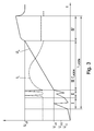
- Fig. 3 shows a schematic timing diagram of the charging current I L and the charging voltage U L of a method for charging batteries.
- the charging method includes, for example, four phases marked with Roman numerals.
- phase I the determination of the state of charge of the battery, for example, by the open-circuit voltage U LL is determined.
- it is checked in the test procedure whether the battery charger can provide the required charging current I L for charging the battery over the set or predetermined charging time t ' charging at all. This is done by applying voltage ramps before the start of the charging phase III.
- the duration of the voltage ramps is in a certain relationship to the specified charging time t ' charging .
- the voltage ramps can be repeated one or more times and the current is measured at the end of the voltage ramp.
- the maximum charging current I L in the charging phase III can be estimated. If the charging current I L can not be provided by the battery charging device, the definitive charging time t ' loading can be increased accordingly. This can be predetermined, for example, by displaying a lower limit for the charging time t charging, min on the battery charging device.
- a depolarization of the battery can be made according to Phase II. This phase is carried out in particular when the open-circuit voltage U LL of the battery is below a certain limit U LLG .
- the duration of the depolarization phase II is selected as a fraction of the effective charging time t ' charging .
- the actual charging begins III.
- the voltage of the battery resulting after the depolarization phase II is now the charging starting voltage U LA of the charging phase III. If no depolarization phase II is carried out, the no-load voltage U LL of the battery would be used as the charge start voltage U LA .
- the charging voltage U L is increased during the charging time t ' charging between the charging start voltage U LA and the charging end voltage U LS determined by the battery.
- the end-of-charge voltage U LS depends on the battery technology used, the number of cells and the battery temperature.
- the charging voltage U L is continuously and linearly increased between the charging starting voltage U LA and the charging end voltage U LS during the charging time t ' charging .
- the charging current I L or the charging voltage U L must be controlled accordingly, so that the desired course of the charging voltage U L , as shown, results.
- the corresponding regulation indirectly takes account of the internal resistance R i of the battery, without, however, actually being measured.
- the definitive time t charging of the main charging III is a fraction of the total charging time t charging available , for example 50-80% thereof.
- the net time for charging III is marked with t ' loading .
- a recharge process IV can be connected to the full charge.
- various known methods for recharging or full charging the battery can be applied.
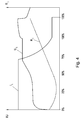
- Fig. 4 shows the curves of the charge current I L of the charge voltage U L and the internal resistance R i of a battery in dependence on the state of charge in the conventional charging method with a constant charging current I L.
- the battery is charged with a constant charging current I L , which is why a corresponding curve for the charging voltage U L results as a function of the complex internal resistance R i of the battery.
- the changing internal resistance R i of the battery is not taken into account.
- the charging current I L remains constant (constant current) or substantially constant (constant power).
- Fig. 5 the curves of the charging current I L of the charging voltage U L and the internal resistance R i of a battery as a function of the state of charge.
- the charging voltage U L is increased from the charging starting voltage U LA of the battery to the charging end voltage U LS .
- the charging current I L must be controlled accordingly, whereby taking into account the changing internal resistance R i is carried out automatically. This results in a profile of the charging current I L , which has a maximum at a substantially medium state of charge (in this case about 30-40%).
- the losses during charging can be reduced and thus also the battery heating can be reduced, which has a positive influence on the battery life.
- the internal resistance R i of the battery is not measured. In contrast to a continuous increase in the charging voltage U L , however, this can also be increased via current pulses or voltage pulses be measured and calculated between the current or voltage pulses, the internal resistance R i of the battery and the next current pulse or voltage pulse to the measured internal resistance R i are adjusted (see Fig. 8 ).
- Fig. 6 shows a variant over the charging method according to Fig. 5 , in which the regulation of the charging current I L or the charging voltage U L is such that the ramp-shaped charging voltage U L has different sections with different slopes.
- the charging process begins with a steeper increase in the charging voltage U L , then passes into a section with a lower slope and ends again with a section with steeper increase of the charging voltage U L to the final charging voltage U LS .
- the maximum of the charging current I L can be reduced with minimal internal resistance R i .
- a charger with a lower maximum charging current I L is sufficient.
- Fig. 7 shows the curves of the charging current I L , the charging voltage U L and the internal resistance R i of a battery as a function of the state of charge at different aging state of the battery. While in a new battery, the internal resistance R i is lower, this increases according to the age of the battery accordingly.
- the curve R ' i shows the course of the internal resistance R i of an aged battery.
- the charging voltage U L is now impressed accordingly and thus remains unchanged, no matter how old the battery is.
- the charging current I L which is regulated in order to achieve the desired course of the charging voltage U L , is correspondingly reduced in the case of an aged battery due to the higher internal resistance R ' i . This is illustrated by the course of the charging current I ' L.
- Fig. 8 shows the curves of the charging current I L , the charging voltage U L and the internal resistance R i of a battery depending on the state of charge in the charging method according to the invention using current pulses, which are controlled to achieve the ramp-shaped course of the charging voltage U L.
- the course of the charging voltage U L is shown only schematically.
- the charging voltage U L will not increase linearly, but according to the pulses of the charging current I L have changes.
- the internal resistance R i is measured and included in the regulation of the charging current I L , in that the charging current I L is regulated as a function of the measured internal resistance R i .
- a reduction of the current to a certain value is sufficient; it is not necessary to reduce the current to zero.
- the voltage response is detected for a specific time and the internal resistance R i is calculated therefrom. Instead of current pulses voltage pulses can be impressed. However, this variant is more complicated by the regulation.
- the charging method according to the invention causes an increased overall efficiency and, due to the thereby reduced temperature increase, an extension of the battery life and thus an extension of the operational capability of the battery, for example in an industrial truck. As a result, there is also less loss of water in the battery.
- the battery can be gently charged.
- a delay of a period of time .DELTA.t v can be carried out (not shown) also before the initiation of the charging phase.
Landscapes
- Engineering & Computer Science (AREA)
- Manufacturing & Machinery (AREA)
- Chemical & Material Sciences (AREA)
- Chemical Kinetics & Catalysis (AREA)
- Electrochemistry (AREA)
- General Chemical & Material Sciences (AREA)
- Power Engineering (AREA)
- Physics & Mathematics (AREA)
- General Physics & Mathematics (AREA)
- Secondary Cells (AREA)
- Charge And Discharge Circuits For Batteries Or The Like (AREA)
Applications Claiming Priority (2)
| Application Number | Priority Date | Filing Date | Title |
|---|---|---|---|
| ATA50382/2012A AT513335B1 (de) | 2012-09-13 | 2012-09-13 | Verfahren und Vorrichtung zum Laden von Batterien |
| EP13791898.3A EP2896105B1 (fr) | 2012-09-13 | 2013-09-09 | Procédé et dispositif de charge de batteries |
Related Parent Applications (2)
| Application Number | Title | Priority Date | Filing Date |
|---|---|---|---|
| EP13791898.3A Division EP2896105B1 (fr) | 2012-09-13 | 2013-09-09 | Procédé et dispositif de charge de batteries |
| EP13791898.3A Division-Into EP2896105B1 (fr) | 2012-09-13 | 2013-09-09 | Procédé et dispositif de charge de batteries |
Publications (1)
| Publication Number | Publication Date |
|---|---|
| EP3136539A1 true EP3136539A1 (fr) | 2017-03-01 |
Family
ID=49585227
Family Applications (2)
| Application Number | Title | Priority Date | Filing Date |
|---|---|---|---|
| EP13791898.3A Active EP2896105B1 (fr) | 2012-09-13 | 2013-09-09 | Procédé et dispositif de charge de batteries |
| EP16190154.1A Withdrawn EP3136539A1 (fr) | 2012-09-13 | 2013-09-09 | Procede et dispositif de chargement de batteries |
Family Applications Before (1)
| Application Number | Title | Priority Date | Filing Date |
|---|---|---|---|
| EP13791898.3A Active EP2896105B1 (fr) | 2012-09-13 | 2013-09-09 | Procédé et dispositif de charge de batteries |
Country Status (5)
| Country | Link |
|---|---|
| US (1) | US9537342B2 (fr) |
| EP (2) | EP2896105B1 (fr) |
| CN (1) | CN104769806B (fr) |
| AT (1) | AT513335B1 (fr) |
| WO (1) | WO2014040104A2 (fr) |
Cited By (1)
| Publication number | Priority date | Publication date | Assignee | Title |
|---|---|---|---|---|
| DE102019218489A1 (de) * | 2019-11-28 | 2021-06-02 | Robert Bosch Gmbh | Verfahren und Vorrichtung zum Laden einer Batterie für ein Fortbewegungsmittel |
Families Citing this family (15)
| Publication number | Priority date | Publication date | Assignee | Title |
|---|---|---|---|---|
| DE102014205167A1 (de) * | 2014-03-20 | 2015-09-24 | Robert Bosch Gmbh | Verfahren zum Nachladen von in Fahrzeugen eingesetzten Batteriezellen und Laderegler zum Ausführen eines solchen Verfahrens |
| DE102016205374A1 (de) * | 2016-03-31 | 2017-10-05 | Siemens Aktiengesellschaft | Verfahren und Vorrichtung zum Laden einer Batterie |
| KR102285148B1 (ko) * | 2016-08-22 | 2021-08-04 | 삼성에스디아이 주식회사 | 배터리 충전 방법 및 이를 이용하는 배터리 충전 장치 |
| US10449615B2 (en) * | 2016-10-31 | 2019-10-22 | Illinois Tool Works Inc. | Hybrid welding modules |
| US11223220B2 (en) | 2016-10-31 | 2022-01-11 | Illinois Tool Works Inc. | Hybrid welding systems and portable hybrid welding modules |
| TWI625915B (zh) * | 2016-11-18 | 2018-06-01 | Industrial Technology Research Institute | 智慧型充電方法 |
| CN107394854A (zh) * | 2017-08-31 | 2017-11-24 | 江苏聚合新能源科技有限公司 | 一种蓄电池动态自然充电方法及系统 |
| CN111525654B (zh) * | 2020-06-02 | 2023-08-22 | 西安稳先半导体科技有限责任公司 | 一种对电池组内各电池分时充电的电路及方法 |
| KR102706438B1 (ko) * | 2021-12-10 | 2024-09-13 | 주식회사 엘지에너지솔루션 | 충전 프로토콜 검사 장치 및 그것의 동작 방법 |
| DE102022200867A1 (de) | 2022-01-26 | 2023-07-27 | Volkswagen Aktiengesellschaft | Verfahren und Vorrichtung zum Laden einer mehrzelligen Batterie |
| US20240429481A1 (en) * | 2023-06-22 | 2024-12-26 | GM Global Technology Operations LLC | Battery electric system with alternating current self-heating mode |
| DE102023118719A1 (de) * | 2023-07-14 | 2025-01-16 | Bayerische Motoren Werke Aktiengesellschaft | Verfahren zum Bestimmen eines Innenwiderstands einer Batteriezelle einer Energiespeichervorrichtung für ein elektrisch antreibbares Kraftfahrzeug, Computerprogramm und/oder computerlesbares Medium, Datenverarbeitungsvorrichtung, elektrisch antreibbares Kraftfahrzeug, Ladesäule |
| DE102023206929A1 (de) | 2023-07-21 | 2025-01-23 | Volkswagen Aktiengesellschaft | Einrichtung zur Kommunikation eines Elektro- oder Hybridfahrzeugs mit einer elektrischen Ladesäule und Kommunikationsverfahren |
| CN118070981B (zh) * | 2024-04-18 | 2024-07-30 | 国网安徽省电力有限公司合肥供电公司 | 基于电力大数据分析的充电桩智能选址分析方法和系统 |
| CN120468702A (zh) * | 2025-07-01 | 2025-08-12 | 杭州方星电子有限公司 | 一种电梯应急铅酸电池寿命分析及系统 |
Citations (7)
| Publication number | Priority date | Publication date | Assignee | Title |
|---|---|---|---|---|
| WO1996016460A1 (fr) | 1994-11-21 | 1996-05-30 | PREMIER ENGINEERED PRODUCTS, INC. doing business as PREMIER ENGINEERING PRODUCTS CORPORATION | Appareil et procede de charge de batterie |
| EP1104074A1 (fr) | 1999-05-07 | 2001-05-30 | Tai-Her Yang | Limiteur de tension pour usage en circuits permettant des ajustages linéaires en parallèle dans des séries de batteries |
| JP2008061373A (ja) | 2006-08-31 | 2008-03-13 | Nagano Japan Radio Co | 充電装置 |
| JP2008187811A (ja) * | 2007-01-30 | 2008-08-14 | Nagano Japan Radio Co | 充電装置 |
| EP2164152A2 (fr) * | 2008-09-16 | 2010-03-17 | Commissariat à l'Energie Atomique | Procédé de charge pulsée d'une batterie dans un système autonome comportant une supercacité |
| EP2244329A1 (fr) | 2009-04-20 | 2010-10-27 | Deutronic Elektronik GmbH | Procédé de charge et de diagnostic pour batteries |
| DE102009051731A1 (de) | 2009-11-03 | 2011-05-05 | Bayerische Motoren Werke Aktiengesellschaft | Verfahren und Vorrichtung zum Laden einer Batterie |
Family Cites Families (11)
| Publication number | Priority date | Publication date | Assignee | Title |
|---|---|---|---|---|
| US5583416A (en) | 1994-01-26 | 1996-12-10 | Gnb Battery Technologies, Inc. | Apparatus and method for step-charging batteries to optimize charge acceptance |
| JP3554057B2 (ja) * | 1995-02-06 | 2004-08-11 | 本田技研工業株式会社 | 電気自動車用蓄電池充電制御装置 |
| US6307352B1 (en) * | 1999-10-19 | 2001-10-23 | Enrev Corporation | High energy charge and depolarization pulse conditioner for an enhanced-reliability lead-acid battery charger |
| JP4292721B2 (ja) * | 2001-02-14 | 2009-07-08 | 株式会社日本自動車部品総合研究所 | ハイブリッド車の電池状態制御方法 |
| JP4523738B2 (ja) * | 2001-06-07 | 2010-08-11 | パナソニック株式会社 | 二次電池の残存容量制御方法および装置 |
| CN1272887C (zh) | 2002-12-31 | 2006-08-30 | 广达电脑股份有限公司 | 两段式充电装置及其充电方法 |
| US8217631B2 (en) * | 2008-01-22 | 2012-07-10 | Honda Motor Co., Ltd. | ACG output voltage control |
| US7808244B2 (en) * | 2008-03-31 | 2010-10-05 | Texas Instruments Incorporated | System and method for determining state of charge of a battery utilizing initial voltage and current measurement and a previous estimate of battery resistance |
| US20120098501A1 (en) * | 2010-10-26 | 2012-04-26 | Tesla Motors, Inc. | Efficient lead acid battery charging |
| CN202014109U (zh) | 2011-03-02 | 2011-10-19 | 江苏嘉钰新能源技术有限公司 | 一种调整电池充电电压的电源 |
| DE102011013967A1 (de) * | 2011-03-15 | 2012-01-05 | Daimler Ag | Verfahren zum Bestimmen eines maximalen Stroms aus einer Batterie |
-
2012
- 2012-09-13 AT ATA50382/2012A patent/AT513335B1/de active
-
2013
- 2013-09-09 CN CN201380057844.3A patent/CN104769806B/zh active Active
- 2013-09-09 EP EP13791898.3A patent/EP2896105B1/fr active Active
- 2013-09-09 US US14/427,676 patent/US9537342B2/en active Active
- 2013-09-09 WO PCT/AT2013/050176 patent/WO2014040104A2/fr not_active Ceased
- 2013-09-09 EP EP16190154.1A patent/EP3136539A1/fr not_active Withdrawn
Patent Citations (8)
| Publication number | Priority date | Publication date | Assignee | Title |
|---|---|---|---|---|
| WO1996016460A1 (fr) | 1994-11-21 | 1996-05-30 | PREMIER ENGINEERED PRODUCTS, INC. doing business as PREMIER ENGINEERING PRODUCTS CORPORATION | Appareil et procede de charge de batterie |
| EP1104074A1 (fr) | 1999-05-07 | 2001-05-30 | Tai-Her Yang | Limiteur de tension pour usage en circuits permettant des ajustages linéaires en parallèle dans des séries de batteries |
| JP2008061373A (ja) | 2006-08-31 | 2008-03-13 | Nagano Japan Radio Co | 充電装置 |
| JP2008187811A (ja) * | 2007-01-30 | 2008-08-14 | Nagano Japan Radio Co | 充電装置 |
| EP2164152A2 (fr) * | 2008-09-16 | 2010-03-17 | Commissariat à l'Energie Atomique | Procédé de charge pulsée d'une batterie dans un système autonome comportant une supercacité |
| US20100066309A1 (en) | 2008-09-16 | 2010-03-18 | Commissariat A L'energie Atomique | Method for pulsed charging of a battery in an autonomous system comprising a supercapacitance |
| EP2244329A1 (fr) | 2009-04-20 | 2010-10-27 | Deutronic Elektronik GmbH | Procédé de charge et de diagnostic pour batteries |
| DE102009051731A1 (de) | 2009-11-03 | 2011-05-05 | Bayerische Motoren Werke Aktiengesellschaft | Verfahren und Vorrichtung zum Laden einer Batterie |
Cited By (2)
| Publication number | Priority date | Publication date | Assignee | Title |
|---|---|---|---|---|
| DE102019218489A1 (de) * | 2019-11-28 | 2021-06-02 | Robert Bosch Gmbh | Verfahren und Vorrichtung zum Laden einer Batterie für ein Fortbewegungsmittel |
| US11628742B2 (en) | 2019-11-28 | 2023-04-18 | Robert Bosch Gmbh | Method and device for charging a battery for a means of transport |
Also Published As
| Publication number | Publication date |
|---|---|
| WO2014040104A3 (fr) | 2014-10-16 |
| CN104769806A (zh) | 2015-07-08 |
| US9537342B2 (en) | 2017-01-03 |
| EP2896105A2 (fr) | 2015-07-22 |
| CN104769806B (zh) | 2018-02-13 |
| US20150249349A1 (en) | 2015-09-03 |
| AT513335B1 (de) | 2017-10-15 |
| EP2896105B1 (fr) | 2017-08-23 |
| AT513335A1 (de) | 2014-03-15 |
| WO2014040104A2 (fr) | 2014-03-20 |
Similar Documents
| Publication | Publication Date | Title |
|---|---|---|
| EP2896105B1 (fr) | Procédé et dispositif de charge de batteries | |
| EP3445607B1 (fr) | Chargeur de batterie et procede correspondant | |
| DE3031887C2 (de) | Verfahren zum Aufladen einer Antriebsbatterie | |
| EP3275040B1 (fr) | Procédé et dispositif de formation d'une batterie | |
| DE102018127530A1 (de) | Berechnung des Maximal-Stroms und Leistungsvorhersage für ein Batterie-Pack | |
| EP2884620B1 (fr) | Procédé de chargement de batteries et convertisseur de chargement | |
| DE102017222975A1 (de) | Steuervorrichtung, Gleichgewichtskorrekturvorrichtung, elektrisches Speichersystem und Einrichtung | |
| EP3708416A1 (fr) | Procédé et dispositif de charge permettant de déterminer une capacité d'accumulation maximale d'un accumulateur d'énergie | |
| DE69216119T2 (de) | Verfahren zur Ladungsoptimierung einer Akkumulatorenbatterie und Vorrichtung zu dessen Durchführung | |
| DE112019005307T5 (de) | Spannungsversorgungssystem und dieses bildende Leistungsquelle | |
| DE112015002996T5 (de) | Balancing-korrektur-steuervorrichtung, balancing-korrektur-system und elektrisches speichersystem | |
| DE102011012316A1 (de) | Verfahren und Vorrichtung zum Laden einer Niedervoltbatterie in einem elektrischen Antriebssystem | |
| DE102016110716A1 (de) | Verfahren und Vorrichtung zum Steuern einer Entladeleistung für eine Speichereinheit | |
| WO2020239577A1 (fr) | Système de gestion de batterie et fonctionnement d'un accumulateur d'énergie électrique | |
| EP2856189B1 (fr) | Procédé et dispositif pour la détermination de la capacité réelle d'une batterie | |
| EP2353215B1 (fr) | Système de surveillance de cellules de condensateur | |
| DE102016001123A1 (de) | Verfahren zum Laden einer Batterie eines Kraftfahrzeugs mittels einer kraftfahrzeugseitigen Solareinrichtung und Kraftfahrzeug | |
| DE102018129426B3 (de) | Verfahren zum aktiven Ladungsausgleich in Energiespeichern | |
| DE102017222217A1 (de) | Verfahren zum Laden einer Batterie, Auswerteeinheit eines Stromnetzes und Automobil | |
| DE4339363A1 (de) | Ladeverfahren für Akkumulatoren | |
| EP4138258B1 (fr) | Procédé de commande d'une valeur limite de courant de charge pour un système de gestion de batterie, système de gestion de batterie | |
| DE102008040696A1 (de) | Verfahren zur Regelung der Ausgangsspannung eines Generators in einem Kraftfahrzeug | |
| DE102022133576A1 (de) | Verfahren zum Laden eines Elektrofahrzeugs in einem V2X-Anwendungsfall | |
| EP3772174A1 (fr) | Dispositif de commande, onduleur, agencement doté d'un onduleur et d'une machine électrique, procédé de fonctionnement d'un onduleur ainsi que programme informatique | |
| DE102019216394A1 (de) | Verfahren zur Regelung des Ladezustands einer Fahrzeugbatterie |
Legal Events
| Date | Code | Title | Description |
|---|---|---|---|
| PUAI | Public reference made under article 153(3) epc to a published international application that has entered the european phase |
Free format text: ORIGINAL CODE: 0009012 |
|
| STAA | Information on the status of an ep patent application or granted ep patent |
Free format text: STATUS: THE APPLICATION HAS BEEN PUBLISHED |
|
| AC | Divisional application: reference to earlier application |
Ref document number: 2896105 Country of ref document: EP Kind code of ref document: P |
|
| AK | Designated contracting states |
Kind code of ref document: A1 Designated state(s): AL AT BE BG CH CY CZ DE DK EE ES FI FR GB GR HR HU IE IS IT LI LT LU LV MC MK MT NL NO PL PT RO RS SE SI SK SM TR |
|
| RIN1 | Information on inventor provided before grant (corrected) |
Inventor name: BINDER, JUERGEN Inventor name: EITELSEBNER, DAVID |
|
| STAA | Information on the status of an ep patent application or granted ep patent |
Free format text: STATUS: THE APPLICATION IS DEEMED TO BE WITHDRAWN |
|
| 18D | Application deemed to be withdrawn |
Effective date: 20170902 |