EP3136574A1 - Steuergerätselbstinbetriebnahme für dreiphasige aktive leistungselektronikwandler - Google Patents
Steuergerätselbstinbetriebnahme für dreiphasige aktive leistungselektronikwandler Download PDFInfo
- Publication number
- EP3136574A1 EP3136574A1 EP16186241.2A EP16186241A EP3136574A1 EP 3136574 A1 EP3136574 A1 EP 3136574A1 EP 16186241 A EP16186241 A EP 16186241A EP 3136574 A1 EP3136574 A1 EP 3136574A1
- Authority
- EP
- European Patent Office
- Prior art keywords
- current
- power converter
- controller
- duty cycle
- cross
- Prior art date
- Legal status (The legal status is an assumption and is not a legal conclusion. Google has not performed a legal analysis and makes no representation as to the accuracy of the status listed.)
- Granted
Links
Images


Classifications
-
- H—ELECTRICITY
- H02—GENERATION; CONVERSION OR DISTRIBUTION OF ELECTRIC POWER
- H02M—APPARATUS FOR CONVERSION BETWEEN AC AND AC, BETWEEN AC AND DC, OR BETWEEN DC AND DC, AND FOR USE WITH MAINS OR SIMILAR POWER SUPPLY SYSTEMS; CONVERSION OF DC OR AC INPUT POWER INTO SURGE OUTPUT POWER; CONTROL OR REGULATION THEREOF
- H02M7/00—Conversion of AC power input into DC power output; Conversion of DC power input into AC power output
- H02M7/42—Conversion of DC power input into AC power output without possibility of reversal
- H02M7/44—Conversion of DC power input into AC power output without possibility of reversal by static converters
- H02M7/48—Conversion of DC power input into AC power output without possibility of reversal by static converters using discharge tubes with control electrode or semiconductor devices with control electrode
- H02M7/53—Conversion of DC power input into AC power output without possibility of reversal by static converters using discharge tubes with control electrode or semiconductor devices with control electrode using devices of a triode or transistor type requiring continuous application of a control signal
- H02M7/537—Conversion of DC power input into AC power output without possibility of reversal by static converters using discharge tubes with control electrode or semiconductor devices with control electrode using devices of a triode or transistor type requiring continuous application of a control signal using semiconductor devices only, e.g. single switched pulse inverters
- H02M7/5387—Conversion of DC power input into AC power output without possibility of reversal by static converters using discharge tubes with control electrode or semiconductor devices with control electrode using devices of a triode or transistor type requiring continuous application of a control signal using semiconductor devices only, e.g. single switched pulse inverters in a bridge configuration
- H02M7/53871—Conversion of DC power input into AC power output without possibility of reversal by static converters using discharge tubes with control electrode or semiconductor devices with control electrode using devices of a triode or transistor type requiring continuous application of a control signal using semiconductor devices only, e.g. single switched pulse inverters in a bridge configuration with automatic control of output voltage or current
-
- H—ELECTRICITY
- H02—GENERATION; CONVERSION OR DISTRIBUTION OF ELECTRIC POWER
- H02J—ELECTRIC POWER NETWORKS; CIRCUIT ARRANGEMENTS OR SYSTEMS FOR SUPPLYING OR DISTRIBUTING ELECTRIC POWER; SYSTEMS FOR STORING ELECTRIC ENERGY
- H02J3/00—Circuit arrangements for AC mains or AC distribution networks
- H02J3/04—Arrangements for connecting networks of the same frequency but supplied from different sources
- H02J3/06—Controlling the transfer of power between connected networks; Controlling load sharing between connected networks
-
- G—PHYSICS
- G05—CONTROLLING; REGULATING
- G05B—CONTROL OR REGULATING SYSTEMS IN GENERAL; FUNCTIONAL ELEMENTS OF SUCH SYSTEMS; MONITORING OR TESTING ARRANGEMENTS FOR SUCH SYSTEMS OR ELEMENTS
- G05B13/00—Adaptive control systems, i.e. systems automatically adjusting themselves to have a performance which is optimum according to some preassigned criterion
- G05B13/02—Adaptive control systems, i.e. systems automatically adjusting themselves to have a performance which is optimum according to some preassigned criterion electric
- G05B13/0205—Adaptive control systems, i.e. systems automatically adjusting themselves to have a performance which is optimum according to some preassigned criterion electric not using a model or a simulator of the controlled system
- G05B13/021—Adaptive control systems, i.e. systems automatically adjusting themselves to have a performance which is optimum according to some preassigned criterion electric not using a model or a simulator of the controlled system in which a variable is automatically adjusted to optimise the performance
- G05B13/022—Adaptive control systems, i.e. systems automatically adjusting themselves to have a performance which is optimum according to some preassigned criterion electric not using a model or a simulator of the controlled system in which a variable is automatically adjusted to optimise the performance using a perturbation of the variable
-
- H—ELECTRICITY
- H02—GENERATION; CONVERSION OR DISTRIBUTION OF ELECTRIC POWER
- H02J—ELECTRIC POWER NETWORKS; CIRCUIT ARRANGEMENTS OR SYSTEMS FOR SUPPLYING OR DISTRIBUTING ELECTRIC POWER; SYSTEMS FOR STORING ELECTRIC ENERGY
- H02J3/00—Circuit arrangements for AC mains or AC distribution networks
- H02J3/001—Arrangements for handling faults or abnormalities, e.g. emergencies or contingencies
- H02J3/0014—Arrangements for handling faults or abnormalities, e.g. emergencies or contingencies for preventing or reducing power oscillations in networks
- H02J3/00142—Oscillations concerning frequency
-
- H—ELECTRICITY
- H02—GENERATION; CONVERSION OR DISTRIBUTION OF ELECTRIC POWER
- H02M—APPARATUS FOR CONVERSION BETWEEN AC AND AC, BETWEEN AC AND DC, OR BETWEEN DC AND DC, AND FOR USE WITH MAINS OR SIMILAR POWER SUPPLY SYSTEMS; CONVERSION OF DC OR AC INPUT POWER INTO SURGE OUTPUT POWER; CONTROL OR REGULATION THEREOF
- H02M1/00—Details of apparatus for conversion
-
- H—ELECTRICITY
- H02—GENERATION; CONVERSION OR DISTRIBUTION OF ELECTRIC POWER
- H02M—APPARATUS FOR CONVERSION BETWEEN AC AND AC, BETWEEN AC AND DC, OR BETWEEN DC AND DC, AND FOR USE WITH MAINS OR SIMILAR POWER SUPPLY SYSTEMS; CONVERSION OF DC OR AC INPUT POWER INTO SURGE OUTPUT POWER; CONTROL OR REGULATION THEREOF
- H02M7/00—Conversion of AC power input into DC power output; Conversion of DC power input into AC power output
- H02M7/66—Conversion of AC power input into DC power output; Conversion of DC power input into AC power output with possibility of reversal
- H02M7/68—Conversion of AC power input into DC power output; Conversion of DC power input into AC power output with possibility of reversal by static converters
- H02M7/72—Conversion of AC power input into DC power output; Conversion of DC power input into AC power output with possibility of reversal by static converters using discharge tubes with control electrode or semiconductor devices with control electrode
- H02M7/79—Conversion of AC power input into DC power output; Conversion of DC power input into AC power output with possibility of reversal by static converters using discharge tubes with control electrode or semiconductor devices with control electrode using devices of a triode or transistor type requiring continuous application of a control signal
- H02M7/797—Conversion of AC power input into DC power output; Conversion of DC power input into AC power output with possibility of reversal by static converters using discharge tubes with control electrode or semiconductor devices with control electrode using devices of a triode or transistor type requiring continuous application of a control signal using semiconductor devices only
-
- H—ELECTRICITY
- H02—GENERATION; CONVERSION OR DISTRIBUTION OF ELECTRIC POWER
- H02P—CONTROL OR REGULATION OF ELECTRIC MOTORS, ELECTRIC GENERATORS OR DYNAMO-ELECTRIC CONVERTERS; CONTROLLING TRANSFORMERS, REACTORS OR CHOKE COILS
- H02P23/00—Arrangements or methods for the control of AC motors characterised by a control method other than vector control
- H02P23/0004—Control strategies in general, e.g. linear type, e.g. P, PI, PID, using robust control
-
- H—ELECTRICITY
- H02—GENERATION; CONVERSION OR DISTRIBUTION OF ELECTRIC POWER
- H02P—CONTROL OR REGULATION OF ELECTRIC MOTORS, ELECTRIC GENERATORS OR DYNAMO-ELECTRIC CONVERTERS; CONTROLLING TRANSFORMERS, REACTORS OR CHOKE COILS
- H02P27/00—Arrangements or methods for the control of AC motors characterised by the kind of supply voltage
- H02P27/04—Arrangements or methods for the control of AC motors characterised by the kind of supply voltage using variable-frequency supply voltage, e.g. inverter or converter supply voltage
- H02P27/06—Arrangements or methods for the control of AC motors characterised by the kind of supply voltage using variable-frequency supply voltage, e.g. inverter or converter supply voltage using DC to AC converters or inverters
-
- H—ELECTRICITY
- H02—GENERATION; CONVERSION OR DISTRIBUTION OF ELECTRIC POWER
- H02J—ELECTRIC POWER NETWORKS; CIRCUIT ARRANGEMENTS OR SYSTEMS FOR SUPPLYING OR DISTRIBUTING ELECTRIC POWER; SYSTEMS FOR STORING ELECTRIC ENERGY
- H02J2101/00—Supply or distribution of decentralised, dispersed or local electric power generation
- H02J2101/20—Dispersed power generation using renewable energy sources
-
- H—ELECTRICITY
- H02—GENERATION; CONVERSION OR DISTRIBUTION OF ELECTRIC POWER
- H02J—ELECTRIC POWER NETWORKS; CIRCUIT ARRANGEMENTS OR SYSTEMS FOR SUPPLYING OR DISTRIBUTING ELECTRIC POWER; SYSTEMS FOR STORING ELECTRIC ENERGY
- H02J3/00—Circuit arrangements for AC mains or AC distribution networks
- H02J3/38—Arrangements for feeding a single network from two or more generators or sources in parallel; Arrangements for feeding already energised networks from additional generators or sources in parallel
- H02J3/381—Dispersed generators
-
- H—ELECTRICITY
- H02—GENERATION; CONVERSION OR DISTRIBUTION OF ELECTRIC POWER
- H02J—ELECTRIC POWER NETWORKS; CIRCUIT ARRANGEMENTS OR SYSTEMS FOR SUPPLYING OR DISTRIBUTING ELECTRIC POWER; SYSTEMS FOR STORING ELECTRIC ENERGY
- H02J3/00—Circuit arrangements for AC mains or AC distribution networks
- H02J3/38—Arrangements for feeding a single network from two or more generators or sources in parallel; Arrangements for feeding already energised networks from additional generators or sources in parallel
- H02J3/46—Controlling the sharing of generated power between the generators, sources or networks
- H02J3/48—Controlling the sharing of active power
-
- Y—GENERAL TAGGING OF NEW TECHNOLOGICAL DEVELOPMENTS; GENERAL TAGGING OF CROSS-SECTIONAL TECHNOLOGIES SPANNING OVER SEVERAL SECTIONS OF THE IPC; TECHNICAL SUBJECTS COVERED BY FORMER USPC CROSS-REFERENCE ART COLLECTIONS [XRACs] AND DIGESTS
- Y02—TECHNOLOGIES OR APPLICATIONS FOR MITIGATION OR ADAPTATION AGAINST CLIMATE CHANGE
- Y02E—REDUCTION OF GREENHOUSE GAS [GHG] EMISSIONS, RELATED TO ENERGY GENERATION, TRANSMISSION OR DISTRIBUTION
- Y02E10/00—Energy generation through renewable energy sources
- Y02E10/50—Photovoltaic [PV] energy
- Y02E10/56—Power conversion systems, e.g. maximum power point trackers
-
- Y—GENERAL TAGGING OF NEW TECHNOLOGICAL DEVELOPMENTS; GENERAL TAGGING OF CROSS-SECTIONAL TECHNOLOGIES SPANNING OVER SEVERAL SECTIONS OF THE IPC; TECHNICAL SUBJECTS COVERED BY FORMER USPC CROSS-REFERENCE ART COLLECTIONS [XRACs] AND DIGESTS
- Y02—TECHNOLOGIES OR APPLICATIONS FOR MITIGATION OR ADAPTATION AGAINST CLIMATE CHANGE
- Y02E—REDUCTION OF GREENHOUSE GAS [GHG] EMISSIONS, RELATED TO ENERGY GENERATION, TRANSMISSION OR DISTRIBUTION
- Y02E10/00—Energy generation through renewable energy sources
- Y02E10/70—Wind energy
- Y02E10/76—Power conversion electric or electronic aspects
Definitions
- the present disclosure relates generally to a power control system and, more specifically, to a control system for an active power converter interfacing an energy source (e.g.,. photovoltaic generator or wind turbine), load (motor drive for elevator) or storage system (e.g. battery), connected to a power grid.
- an energy source e.g.,. photovoltaic generator or wind turbine
- load motor drive for elevator
- storage system e.g. battery
- Three-phase grid-connected power electronics converters are widely applied on areas such as regenerative drives, energy storage connected to the grid, and renewable generation and transportation.
- the grid impedance interacts with the local control. This may results in an otherwise stable controller becoming unstable (or having low stability margins) when installed on end-user facilities.
- the grid impedance of end-user facilities is typically unknown at the time of installation, which may require the installer to have advanced technical knowledge, and/or result in a delayed commissioning process.
- Self-commissioning techniques for power electronic converters can be used to handle uncertainty of model parameters.
- techniques may assume a fixed motor model and control strategy. Techniques may also apply perturbations on several frequencies.
- a system for modulating a current level of a power converter connected to the grid comprises a perturbation module that injects a sinusoidal signal, at a single frequency that is the cross-over frequency of the controller of the power converter, to provide a duty cycle to a power converter connected to a power grid, a current controller that monitors a reference current provided by a voltage controller of a DC link interfacing the grid connected converter with a motor drive, storage system or generation system, the current controller further monitors a current of the grid-side terminals of the power converter, and a parameter calculation module that calculates a plurality of gain values for the current controller based at least in part on a phase margin, a cross-over frequency, a current of an alternating current side of the power converter, and the duty cycle.
- duty cycle is further determined by a modulation of the perturbation injection and an output of the current controller.
- a magnitude and phase are calculated by taking discrete Fourier transforms of both the current and the duty cycle calculated at the cross-over frequency.
- the plurality of gain values include at least a proportional gain value.
- a method for modulating a current level of an alternating current side of the power converter includes injecting a sinusoidal signal, at a single predetermined cross-over frequency, to provide a perturbation to the duty cycle of a power converter connected to the power grid, monitoring a current of an alternating current side of the power converter, monitoring a duty cycle and calculating a plurality of gain values for the current controller based at least in part on a phase margin, a cross-over frequency, the current of an alternating current side of the power converter, and the duty cycle.
- duty cycle is further determined by a modulation of the perturbation injection and an output of the current controller.
- further embodiments could include the output of the current controller is determined by the gain values calculated by the regulation module and the current of an alternating current side of the power converter.
- further embodiments could include a magnitude and a phase are calculated by taking discrete Fourier transforms of both the current and the duty cycle calculated at the cross-over frequency.
- further embodiments could include the plurality of gain values include a proportional gain value, an integral gain value, and a derivative gain value.
- cross-over frequency is a single frequency and is a fixed value.
- an elevator system 10 may include a stationary support structure 11 that may generally be an integral part of a multi-story building, and at least one lane (i.e., three lanes 13, 15, 17 illustrated) having boundaries generally defined by the structure 11.
- the elevator system 10 further includes at least one car 14 that travels within at least one of the lanes 13, 15, 17.
- the car 14 may travel in a vertical direction, and may further be in a dedicated upward direction in lane 15 and a dedicated downward direction in lane 13 (as one, non-limiting, example). It is further contemplated and understood that the elevator system 10 may be self-propelled, and may have multiple cars 14 traveling in any one lane 13, 15, 17 with the multiple cars traveling in an upward direction in lane 15 and a downward direction in lane 13. In other embodiments, cars 14 may travel in two directions in a single lane.
- the elevator system 10 may further include at least one transfer station 30 generally located at or above the top floor and at or below the bottom floor.
- the at least one transfer station 30 may impart horizontal movement of the cars 14, thereby facilitating transfer of the cars 14 between lanes 13, 15, 17.
- one or more intermediate transfer stations, similar to station 30 may be used between the first floor and the top floor.
- a lower transfer station 32 may be located at or below the bottom floor.
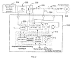
- FIG. 2 illustrates a controller 200 in accordance with one embodiment.
- the controller 200 may be connected to an electrical distribution system.
- the electrical distribution system may be connected to a motor drive 204 of an industrial system, which imparts motion on an elevator system 10, for example.
- controller 200 may be applied to any drive application including a roped elevator system.
- controller 200 may also be applied to a heating, ventilation and air conditioning system, or any system connected to an electrical grid.
- the controller 200 and the electrical distribution system may be connected to a renewable generation system, or a storage system of an industrial system through a power converter 206, filter composed of inductors 218, 220, capacitor 224, and a DC link 222.
- the electrical distribution system may include a power converter 206 that interfaces the motor drive 204 with the grid, for example.
- the controller 200 may monitor a reference current provided by a power converter 206, which may provide a direct current link interfacing the industrial system with the grid 208.
- the power converter 206 is a bidirectional voltage-source-converter made up at least by six insulated-gate bipolar transistors (IGBTs).
- IGBTs insulated-gate bipolar transistors
- the power converter 206 is connected to the grid 208.
- the grid 208 may have a large impedance, compared with a conventional power grid. Accordingly, regulation of the power converter 206 may be required to ensure that an adequate level of power is provided to or from the motor drive 204.
- the regulation of the power converter 206 may be provided by a duty cycle generated by the controller 200 and can be based at least in part on the impedance of the grid 208.
- the controller 200 may monitor a current supplied to the grid-side terminals of the power converter 206, which supplies current to the motor drive 204 from the grid 208, or vice versa, as part of a current control configuration, the grid voltage used as part of a phase-locked loop (PLL) and as part of other functions incorporated into the current controller, such as feed-forward compensation or active damping, and the DC link bus voltage as part of a voltage control configuration of the voltage controller 226.
- PLL phase-locked loop
- the system is bidirectional, so the motor drive will provide power to the grid 208 during regenerative operation.
- the current controller may be implemented in stationary reference frame (either a-b-c frame or alpha-beta frame) or synchronous reference frame (d-q frame), for example, and may incorporate filters and de-coupling networks.
- the controller 200 may command the power converter 206 with a desired duty cycle, to operate in dynamically stable conditions and with dynamic performance determined by the phase margin and cross-over frequency specifications given as an input for the controller, for any required level of power for the motor drive 204 or another external system connected to the grid 208.
- the controller 200 may include a perturbation module 210.
- the perturbation module injects a sinusoidal signal as part of the duty cycle regulation of the power converter 206.
- the sinusoidal signal is injected at a single cross-over frequency, for example 480 hertz.
- the single cross-over frequency may be specified at the time of system installation. The need for a spectrum of frequencies to be applied to the perturbation signal is mitigated by the configuration disclosed in the embodiment of FIG. 2 .
- using a single frequency instead of multiple frequencies leads to dramatic reduction of time required to identify parameters of a plant of the power converter required to tune the current controller and simpler implementation of the parameter calculation function.
- the controller 200 further comprises a current controller 212, a commissioning controller 213 and a voltage controller 226.
- the voltage controller 226 can be a DC link voltage controller.
- the current controller 212 monitors a reference signal provided by a voltage controller of the direct current link of the motor drive 204, and a grid side current, for example.
- the current controller 212 outputs a signal that is modulated with the sinusoidal signal.
- the modulated signal is injected as a duty cycle regulation of the power converter 206.
- the commissioning controller 213 can be applied in a similar manner to other types of controllers, such as a DC link voltage controller.
- the modulation of the sinusoidal signal provided by the perturbation module 210 and the current controller determines a duty cycle of the power converter 206.
- the power converter 206 provides bi-directional regulation of the current at the grid-side terminal.
- Inductors 218, 220 and capacitor 224 may be present within the filter of the power converter, although a filter topology that does not include inductor 220 and capacitor 224, as well as other variations of these structures, may be present.
- the impedance may change because of variations of the grid 208 and any other loads connected to the grid 208.
- the commissioning controller 213 of the controller 200 further includes a parameter calculation module 216 that calculates a plurality of gain values for the current controller 212.
- the plurality of gain values may be based at least in part on a phase margin, cross-over frequency, the power converter AC current, and the duty cycle.
- the parameter calculation module 216 calculates the gain values for the current controller 212 based in part upon a magnitude value and a phase value generated by a magnitude and phase calculation.
- the gain values for the current controller 212 can be calculated in a variety of ways based on the required phase margin and cross-over frequency for the loop gain, and magnitude and phase of the controlled plant. Some examples are provided below based on simple analytical expressions on continuous time domain. In those equations, Plant i represents the dynamic relation between the power converter AC current "i L1 " and the duty cycle "d", ⁇ cross represents the cross-over frequency, and PM represents the phase margin.
- a PI controller can be used in one embodiment.
- the parameters fitting is carried out based on the system of equations (1).
- a PID may be useful for phase boosting and enhancement of dynamic performance when phase lag is significant due to digital delays.
- the implementation herein considered includes two coincident zeroes and two coincident high frequency poles, where the poles and the zeroes are separated in frequency by a factor K i .
- the parameters fitting is carried out based on the system of equations (2).
- ⁇ PID s K p ⁇ 1 s ⁇ 1 + s ⁇ K j ⁇ cross 2 1 + s ⁇ 1 K j ⁇ ⁇ cross 2
- K j tan 1 4 ⁇ ⁇ 2 + PM ⁇ arg Plant i j ⁇ cross ⁇ cross
- K p ⁇ cross Plant i j ⁇ cross ⁇ K j 2
- linear controllers such as PI compensator including Resonant compensators, are also considered in this disclosure and may be tuned following a similar procedure. Also, the plant may be calculated based on other AC current magnitude, such as i L2 .
- a magnitude and phase module 215 calculates a magnitude and a phase of a plant of the power converter based on a relationship between a current at an alternating side of the power converter and the duty cycle at the cross-over frequency.
- the magnitude and phase are generated by taking Discrete Fourier Transforms of both the current and the duty cycle calculated at the cross-over frequency as a function of the current on the alternating current side of the power converter and the duty cycle of the perturbation signal. Those signals may be preprocessed before applying the Discrete Fourier Transform using, for example, band-pass filters. Instead of Discrete Fourier Transform, alternative means for calculation of magnitude and phase at the cross-over frequency may be applied.
- the gain values are additionally calculated by using the cross-over frequency and a phase margin value.
- the gain values may include a proportional gain value, an integral gain value, and a derivative gain value.
- the gain values are transmitted by the parameter calculation module 216 to the current controller 212.
- the current controller 212 measures the current flowing through the power converter 206.
- the reference for the current controller 212 of the current flowing through the power converter 206 may be provided by a voltage controller 226 regulating a voltage across a capacitor in a DC link 222.
- the regulating capacitor of the DC link 222 may be connected in parallel with the power converter 206 and the motor drive 204, for example.
- any suitable configuration may be possible to generate the reference current for the current controller 212 of the current of the alternating current side of the power converter 206.
- the current controller 212 applies the proportional gain value, the integral gain value, and the derivative gain value to the error between the measured grid current value and the reference current value.
- the current controller 212 may include other configurations capable of providing additional gain values.
- the current controller 212 generates the adjusted grid current value, which is then modulated with the sinusoidal signal generated by the perturbation module 210.
- FIG. 3 illustrates a method of current regulation in accordance with one embodiment of the present disclosure.
- a sinusoidal signal may be injected at a single predetermined cross-over frequency.
- the sinusoidal signal may provide a perturbation to the duty cycle to a power converter connected to a power grid, for example.
- the duty cycle may be further determined by a modulation of the perturbation injection and an output of the current controller.
- an AC current of a power converter connected to the power grid may be monitored.
- the current may be a measured value across an inductance of the converter AC filter.
- a duty cycle of a power converter is monitored.
- a plurality of gain values for the current controller are calculated.
- the plurality of gain values may be based at least in part on a phase margin, a cross-over frequency, the AC current of the power converter, and the duty cycle modulated by the injected sinusoidal signal.
- the plurality of gain values may be based additionally on a magnitude and phase calculation provided by discrete Fourier transforms of both the current and the duty cycle calculated at a single cross-over frequency.
Landscapes
- Engineering & Computer Science (AREA)
- Power Engineering (AREA)
- Medical Informatics (AREA)
- Artificial Intelligence (AREA)
- Computer Vision & Pattern Recognition (AREA)
- Evolutionary Computation (AREA)
- Health & Medical Sciences (AREA)
- Software Systems (AREA)
- Physics & Mathematics (AREA)
- General Physics & Mathematics (AREA)
- Automation & Control Theory (AREA)
- Inverter Devices (AREA)
- Control Of Ac Motors In General (AREA)
Applications Claiming Priority (1)
| Application Number | Priority Date | Filing Date | Title |
|---|---|---|---|
| US201562212168P | 2015-08-31 | 2015-08-31 |
Publications (2)
| Publication Number | Publication Date |
|---|---|
| EP3136574A1 true EP3136574A1 (de) | 2017-03-01 |
| EP3136574B1 EP3136574B1 (de) | 2020-07-01 |
Family
ID=57209156
Family Applications (1)
| Application Number | Title | Priority Date | Filing Date |
|---|---|---|---|
| EP16186241.2A Active EP3136574B1 (de) | 2015-08-31 | 2016-08-30 | Steuergerätselbstinbetriebnahme für dreiphasige aktive leistungselektronikwandler |
Country Status (4)
| Country | Link |
|---|---|
| US (1) | US10033318B2 (de) |
| EP (1) | EP3136574B1 (de) |
| CN (1) | CN106487020B (de) |
| ES (1) | ES2818048T3 (de) |
Cited By (2)
| Publication number | Priority date | Publication date | Assignee | Title |
|---|---|---|---|---|
| CN114172201A (zh) * | 2021-12-10 | 2022-03-11 | 国网福建省电力有限公司 | 一种模块化直驱风机控制模型结构识别方法 |
| CN116979671A (zh) * | 2023-09-25 | 2023-10-31 | 江苏省现代交通节能减排工程技术研究中心 | 一种风光发电用储能电池组充放电安全管理系统 |
Families Citing this family (3)
| Publication number | Priority date | Publication date | Assignee | Title |
|---|---|---|---|---|
| JP6174271B2 (ja) * | 2014-10-31 | 2017-08-02 | 株式会社日立製作所 | 系統安定化制御装置及び方法 |
| CN112444706B (zh) * | 2019-08-28 | 2025-01-21 | 台达电子企业管理(上海)有限公司 | 应用于电力系统的绝缘监测装置与电力系统 |
| CN115411774B (zh) * | 2022-09-19 | 2025-09-26 | 新风光电子科技股份有限公司 | 一种基于非最小相位系统和直流功率前馈的恒压控制方法 |
Citations (4)
| Publication number | Priority date | Publication date | Assignee | Title |
|---|---|---|---|---|
| EP0936730A2 (de) * | 1997-12-22 | 1999-08-18 | Otis Elevator Company | Selbsttätiger Inbetriebnahmeregler für ein feldorientiertes Aufzugsmotorantriebssystem |
| WO2013142553A2 (en) * | 2012-03-23 | 2013-09-26 | General Electric Company | System and method for islanding detection and protection |
| US20130268219A1 (en) * | 2012-04-09 | 2013-10-10 | Utah State University | Fractional Order Power Point Tracking |
| EP2871743A1 (de) * | 2013-11-11 | 2015-05-13 | Siemens Aktiengesellschaft | Windkraftwerk, Windpark und Verfahren zum Betreiben |
Family Cites Families (20)
| Publication number | Priority date | Publication date | Assignee | Title |
|---|---|---|---|---|
| US6622099B2 (en) | 2000-08-14 | 2003-09-16 | Kollmorgen Corporation | Frequency domain auto-tune for an internal motor controller |
| AUPS143902A0 (en) | 2002-03-28 | 2002-05-09 | Curtin University Of Technology | Power conversion system and method of converting power |
| US7372174B2 (en) | 2005-11-11 | 2008-05-13 | Converteam Ltd | Power converters |
| WO2008043039A2 (en) | 2006-10-04 | 2008-04-10 | The Regents Of The University Of California | Unified control of single and three-phase power converters |
| KR100886194B1 (ko) | 2007-06-08 | 2009-02-27 | 한국전기연구원 | 계통 연계형 고압 권선형 유도 발전기 제어 장치 |
| ES2338396B1 (es) | 2007-12-27 | 2011-04-08 | GAMESA INNOVATION & TECHONOLOGY S.L. | Instalacion de energia eolica y procedimiento para su funcionamiento. |
| WO2010018424A1 (en) | 2008-08-12 | 2010-02-18 | Vestas Wind Systems A/S | A power regulation scheme for a converter feeding into an asymmetrical grid |
| WO2010114792A1 (en) | 2009-04-01 | 2010-10-07 | The Board Of Trustees Of The University Of Alabama | Intelligent power converter control for grid integration of renewable energies |
| DE102009042865A1 (de) | 2009-04-16 | 2011-05-19 | Kühn, Walter, Prof. Dr. Ing. | Verfahren und Vorrichtung zur automatischen Stabilisierung eines Netzes die für elektrische Energieversorgung mit zumindest einem Stromrichter |
| WO2012009367A1 (en) | 2010-07-12 | 2012-01-19 | Advanced Energy Industries, Inc. | Power inverter systems with high-accuracy reference signal generation and associated methods of control |
| EP2485358B2 (de) | 2011-02-07 | 2021-12-22 | Siemens Gamesa Renewable Energy A/S | System und Verfahren zur Abschwächung eines elektrischen Ungleichgewichts eines Dreiphasenstroms an einem gemeinsamen Anschlusspunkt zwischen einem Windpark und einem Stromnetz |
| ES2616207T3 (es) | 2011-12-23 | 2017-06-09 | Vlaamse Instelling Voor Technologisch Onderzoek (Vito) | Sistema para distribuir energía eléctrica entre un grupo de dispositivos eléctricos, método para distribuir energía eléctrica entre un grupo de dispositivos eléctricos de dicho sistema, y controlador utilizable en dicho sistema |
| US9093928B2 (en) | 2012-04-24 | 2015-07-28 | General Electric Company | Methods and systems for controlling a power converter |
| CN102749488A (zh) | 2012-06-27 | 2012-10-24 | 南京信息工程大学 | 电网谐波实时在线监测仪及利用该监测仪检测谐波的方法 |
| US9411389B2 (en) | 2012-10-09 | 2016-08-09 | Nec Corporation | Distributed generation control for microgrid during islanding |
| US9331487B2 (en) | 2013-03-14 | 2016-05-03 | Rockwell Automation Technologies, Inc. | Method and apparatus for islanding detection for grid tie converters |
| US9651977B2 (en) | 2013-03-14 | 2017-05-16 | Hiq Solar, Inc. | Three-phase power conversion with power factor correction operational day and night |
| CN103257271B (zh) | 2013-05-16 | 2016-04-06 | 南京工程学院 | 一种基于stm32f107vct6的微电网谐波与间谐波检测装置及检测方法 |
| US9484745B2 (en) | 2013-09-09 | 2016-11-01 | Rutgers, The State University Of New Jersey | Virtual oscillator control of power electronics inverters |
| CN104135026A (zh) | 2014-06-12 | 2014-11-05 | 东南大学 | 一种提高微网系统电能质量的控制方法 |
-
2016
- 2016-08-30 ES ES16186241T patent/ES2818048T3/es active Active
- 2016-08-30 US US15/251,246 patent/US10033318B2/en active Active
- 2016-08-30 CN CN201610767339.3A patent/CN106487020B/zh active Active
- 2016-08-30 EP EP16186241.2A patent/EP3136574B1/de active Active
Patent Citations (4)
| Publication number | Priority date | Publication date | Assignee | Title |
|---|---|---|---|---|
| EP0936730A2 (de) * | 1997-12-22 | 1999-08-18 | Otis Elevator Company | Selbsttätiger Inbetriebnahmeregler für ein feldorientiertes Aufzugsmotorantriebssystem |
| WO2013142553A2 (en) * | 2012-03-23 | 2013-09-26 | General Electric Company | System and method for islanding detection and protection |
| US20130268219A1 (en) * | 2012-04-09 | 2013-10-10 | Utah State University | Fractional Order Power Point Tracking |
| EP2871743A1 (de) * | 2013-11-11 | 2015-05-13 | Siemens Aktiengesellschaft | Windkraftwerk, Windpark und Verfahren zum Betreiben |
Non-Patent Citations (1)
| Title |
|---|
| REFEREX, 2001, XP040425239 * |
Cited By (4)
| Publication number | Priority date | Publication date | Assignee | Title |
|---|---|---|---|---|
| CN114172201A (zh) * | 2021-12-10 | 2022-03-11 | 国网福建省电力有限公司 | 一种模块化直驱风机控制模型结构识别方法 |
| CN114172201B (zh) * | 2021-12-10 | 2023-06-23 | 国网福建省电力有限公司 | 一种模块化直驱风机控制模型结构识别方法 |
| CN116979671A (zh) * | 2023-09-25 | 2023-10-31 | 江苏省现代交通节能减排工程技术研究中心 | 一种风光发电用储能电池组充放电安全管理系统 |
| CN116979671B (zh) * | 2023-09-25 | 2023-12-19 | 江苏省现代交通节能减排工程技术研究中心 | 一种风光发电用储能电池组充放电安全管理系统 |
Also Published As
| Publication number | Publication date |
|---|---|
| CN106487020A (zh) | 2017-03-08 |
| ES2818048T3 (es) | 2021-04-09 |
| US20170063267A1 (en) | 2017-03-02 |
| CN106487020B (zh) | 2021-12-10 |
| EP3136574B1 (de) | 2020-07-01 |
| US10033318B2 (en) | 2018-07-24 |
Similar Documents
| Publication | Publication Date | Title |
|---|---|---|
| EP3136574B1 (de) | Steuergerätselbstinbetriebnahme für dreiphasige aktive leistungselektronikwandler | |
| Blahnik et al. | Control of a single-phase cascaded H-bridge active rectifier under unbalanced load | |
| US8796884B2 (en) | Energy conversion systems with power control | |
| CN102223094B (zh) | 电力转换系统及其中lc电路阻尼方法 | |
| US20100157632A1 (en) | Energy Conversion Systems With Power Control | |
| US20160268917A1 (en) | Predictive current control in bidirectional power converter | |
| CN102222937B (zh) | 一种光伏并网逆变器及其并网控制方法 | |
| US8970159B2 (en) | Method for compensating instantaneous power failure in medium voltage inverter and medium voltage inverter system by using the same | |
| US9973103B1 (en) | System for power conversion with reactive power compensation | |
| CN102983620B (zh) | 一种辅助变流器及其并联控制方法 | |
| Narang et al. | An algorithm for fast flexible power point tracking in photovoltaic power plants | |
| Nadweh et al. | Using four–quadrant chopper with variable speed drive system dc-link to improve the quality of supplied power for industrial facilities | |
| US20150091532A1 (en) | Method of controlling charging of a battery | |
| CN112865063A (zh) | 能量路由器和车辆运行控制方法、存储介质 | |
| Lei et al. | Multi-loop control algorithms for seamless transition of grid-connected inverter | |
| Chen et al. | Modeling and triple-loop control of ZVS grid-connected DC/AC converters for three-phase balanced microinverter application | |
| CN110061488B (zh) | 考虑直流微网不平衡电流变化率的混合储能分频控制方法 | |
| Bauer | Single phase voltage source inverter photovoltaic application | |
| CN108039730B (zh) | 一种地铁能量回馈装置的控制系统及其控制方法 | |
| Heising et al. | Improvement of low-frequency railway power system stability using an advanced multivariable control concept | |
| Heising et al. | Single-phase 50-kW 16.7-Hz four-quadrant line-side converter for railway traction application | |
| Xu et al. | Dead-time compensation and single-loop control strategy for ground power unit | |
| Elhaj et al. | Contribution of a shunt active power filter control using double fuzzy PI controller | |
| CN109217661B (zh) | 用于控制斩波电路开关频率的方法与装置 | |
| Gulyaeva et al. | Repetitive Control Method for Suppression of Higher Harmonics in Supply Current of Subway Couches |
Legal Events
| Date | Code | Title | Description |
|---|---|---|---|
| PUAI | Public reference made under article 153(3) epc to a published international application that has entered the european phase |
Free format text: ORIGINAL CODE: 0009012 |
|
| STAA | Information on the status of an ep patent application or granted ep patent |
Free format text: STATUS: THE APPLICATION HAS BEEN PUBLISHED |
|
| AK | Designated contracting states |
Kind code of ref document: A1 Designated state(s): AL AT BE BG CH CY CZ DE DK EE ES FI FR GB GR HR HU IE IS IT LI LT LU LV MC MK MT NL NO PL PT RO RS SE SI SK SM TR |
|
| AX | Request for extension of the european patent |
Extension state: BA ME |
|
| STAA | Information on the status of an ep patent application or granted ep patent |
Free format text: STATUS: REQUEST FOR EXAMINATION WAS MADE |
|
| RAP1 | Party data changed (applicant data changed or rights of an application transferred) |
Owner name: OTIS ELEVATOR COMPANY |
|
| 17P | Request for examination filed |
Effective date: 20170829 |
|
| RBV | Designated contracting states (corrected) |
Designated state(s): AL AT BE BG CH CY CZ DE DK EE ES FI FR GB GR HR HU IE IS IT LI LT LU LV MC MK MT NL NO PL PT RO RS SE SI SK SM TR |
|
| STAA | Information on the status of an ep patent application or granted ep patent |
Free format text: STATUS: EXAMINATION IS IN PROGRESS |
|
| 17Q | First examination report despatched |
Effective date: 20180124 |
|
| RIC1 | Information provided on ipc code assigned before grant |
Ipc: H02J 3/48 20060101ALN20191202BHEP Ipc: H02M 1/00 20060101AFI20191202BHEP Ipc: G05B 13/02 20060101ALI20191202BHEP Ipc: H02J 3/38 20060101ALN20191202BHEP Ipc: H02M 7/797 20060101ALI20191202BHEP Ipc: H02M 7/5387 20070101ALI20191202BHEP Ipc: H02J 3/24 20060101ALN20191202BHEP Ipc: B66B 1/00 20060101ALI20191202BHEP |
|
| GRAP | Despatch of communication of intention to grant a patent |
Free format text: ORIGINAL CODE: EPIDOSNIGR1 |
|
| STAA | Information on the status of an ep patent application or granted ep patent |
Free format text: STATUS: GRANT OF PATENT IS INTENDED |
|
| INTG | Intention to grant announced |
Effective date: 20200121 |
|
| GRAS | Grant fee paid |
Free format text: ORIGINAL CODE: EPIDOSNIGR3 |
|
| GRAA | (expected) grant |
Free format text: ORIGINAL CODE: 0009210 |
|
| STAA | Information on the status of an ep patent application or granted ep patent |
Free format text: STATUS: THE PATENT HAS BEEN GRANTED |
|
| AK | Designated contracting states |
Kind code of ref document: B1 Designated state(s): AL AT BE BG CH CY CZ DE DK EE ES FI FR GB GR HR HU IE IS IT LI LT LU LV MC MK MT NL NO PL PT RO RS SE SI SK SM TR |
|
| REG | Reference to a national code |
Ref country code: CH Ref legal event code: EP Ref country code: AT Ref legal event code: REF Ref document number: 1287111 Country of ref document: AT Kind code of ref document: T Effective date: 20200715 |
|
| REG | Reference to a national code |
Ref country code: IE Ref legal event code: FG4D |
|
| REG | Reference to a national code |
Ref country code: DE Ref legal event code: R096 Ref document number: 602016039008 Country of ref document: DE |
|
| REG | Reference to a national code |
Ref country code: LT Ref legal event code: MG4D |
|
| PG25 | Lapsed in a contracting state [announced via postgrant information from national office to epo] |
Ref country code: BG Free format text: LAPSE BECAUSE OF FAILURE TO SUBMIT A TRANSLATION OF THE DESCRIPTION OR TO PAY THE FEE WITHIN THE PRESCRIBED TIME-LIMIT Effective date: 20201001 |
|
| REG | Reference to a national code |
Ref country code: NL Ref legal event code: MP Effective date: 20200701 |
|
| REG | Reference to a national code |
Ref country code: AT Ref legal event code: MK05 Ref document number: 1287111 Country of ref document: AT Kind code of ref document: T Effective date: 20200701 |
|
| PG25 | Lapsed in a contracting state [announced via postgrant information from national office to epo] |
Ref country code: AT Free format text: LAPSE BECAUSE OF FAILURE TO SUBMIT A TRANSLATION OF THE DESCRIPTION OR TO PAY THE FEE WITHIN THE PRESCRIBED TIME-LIMIT Effective date: 20200701 Ref country code: SE Free format text: LAPSE BECAUSE OF FAILURE TO SUBMIT A TRANSLATION OF THE DESCRIPTION OR TO PAY THE FEE WITHIN THE PRESCRIBED TIME-LIMIT Effective date: 20200701 Ref country code: PT Free format text: LAPSE BECAUSE OF FAILURE TO SUBMIT A TRANSLATION OF THE DESCRIPTION OR TO PAY THE FEE WITHIN THE PRESCRIBED TIME-LIMIT Effective date: 20201102 Ref country code: HR Free format text: LAPSE BECAUSE OF FAILURE TO SUBMIT A TRANSLATION OF THE DESCRIPTION OR TO PAY THE FEE WITHIN THE PRESCRIBED TIME-LIMIT Effective date: 20200701 Ref country code: LT Free format text: LAPSE BECAUSE OF FAILURE TO SUBMIT A TRANSLATION OF THE DESCRIPTION OR TO PAY THE FEE WITHIN THE PRESCRIBED TIME-LIMIT Effective date: 20200701 Ref country code: CZ Free format text: LAPSE BECAUSE OF FAILURE TO SUBMIT A TRANSLATION OF THE DESCRIPTION OR TO PAY THE FEE WITHIN THE PRESCRIBED TIME-LIMIT Effective date: 20200701 Ref country code: FI Free format text: LAPSE BECAUSE OF FAILURE TO SUBMIT A TRANSLATION OF THE DESCRIPTION OR TO PAY THE FEE WITHIN THE PRESCRIBED TIME-LIMIT Effective date: 20200701 Ref country code: NO Free format text: LAPSE BECAUSE OF FAILURE TO SUBMIT A TRANSLATION OF THE DESCRIPTION OR TO PAY THE FEE WITHIN THE PRESCRIBED TIME-LIMIT Effective date: 20201001 Ref country code: GR Free format text: LAPSE BECAUSE OF FAILURE TO SUBMIT A TRANSLATION OF THE DESCRIPTION OR TO PAY THE FEE WITHIN THE PRESCRIBED TIME-LIMIT Effective date: 20201002 |
|
| PG25 | Lapsed in a contracting state [announced via postgrant information from national office to epo] |
Ref country code: LV Free format text: LAPSE BECAUSE OF FAILURE TO SUBMIT A TRANSLATION OF THE DESCRIPTION OR TO PAY THE FEE WITHIN THE PRESCRIBED TIME-LIMIT Effective date: 20200701 Ref country code: RS Free format text: LAPSE BECAUSE OF FAILURE TO SUBMIT A TRANSLATION OF THE DESCRIPTION OR TO PAY THE FEE WITHIN THE PRESCRIBED TIME-LIMIT Effective date: 20200701 Ref country code: PL Free format text: LAPSE BECAUSE OF FAILURE TO SUBMIT A TRANSLATION OF THE DESCRIPTION OR TO PAY THE FEE WITHIN THE PRESCRIBED TIME-LIMIT Effective date: 20200701 Ref country code: IS Free format text: LAPSE BECAUSE OF FAILURE TO SUBMIT A TRANSLATION OF THE DESCRIPTION OR TO PAY THE FEE WITHIN THE PRESCRIBED TIME-LIMIT Effective date: 20201101 |
|
| PG25 | Lapsed in a contracting state [announced via postgrant information from national office to epo] |
Ref country code: NL Free format text: LAPSE BECAUSE OF FAILURE TO SUBMIT A TRANSLATION OF THE DESCRIPTION OR TO PAY THE FEE WITHIN THE PRESCRIBED TIME-LIMIT Effective date: 20200701 Ref country code: MC Free format text: LAPSE BECAUSE OF FAILURE TO SUBMIT A TRANSLATION OF THE DESCRIPTION OR TO PAY THE FEE WITHIN THE PRESCRIBED TIME-LIMIT Effective date: 20200701 |
|
| REG | Reference to a national code |
Ref country code: CH Ref legal event code: PL |
|
| REG | Reference to a national code |
Ref country code: DE Ref legal event code: R097 Ref document number: 602016039008 Country of ref document: DE |
|
| REG | Reference to a national code |
Ref country code: ES Ref legal event code: FG2A Ref document number: 2818048 Country of ref document: ES Kind code of ref document: T3 Effective date: 20210409 |
|
| PG25 | Lapsed in a contracting state [announced via postgrant information from national office to epo] |
Ref country code: IT Free format text: LAPSE BECAUSE OF FAILURE TO SUBMIT A TRANSLATION OF THE DESCRIPTION OR TO PAY THE FEE WITHIN THE PRESCRIBED TIME-LIMIT Effective date: 20200701 Ref country code: EE Free format text: LAPSE BECAUSE OF FAILURE TO SUBMIT A TRANSLATION OF THE DESCRIPTION OR TO PAY THE FEE WITHIN THE PRESCRIBED TIME-LIMIT Effective date: 20200701 Ref country code: LU Free format text: LAPSE BECAUSE OF NON-PAYMENT OF DUE FEES Effective date: 20200830 Ref country code: LI Free format text: LAPSE BECAUSE OF NON-PAYMENT OF DUE FEES Effective date: 20200831 Ref country code: SM Free format text: LAPSE BECAUSE OF FAILURE TO SUBMIT A TRANSLATION OF THE DESCRIPTION OR TO PAY THE FEE WITHIN THE PRESCRIBED TIME-LIMIT Effective date: 20200701 Ref country code: RO Free format text: LAPSE BECAUSE OF FAILURE TO SUBMIT A TRANSLATION OF THE DESCRIPTION OR TO PAY THE FEE WITHIN THE PRESCRIBED TIME-LIMIT Effective date: 20200701 Ref country code: CH Free format text: LAPSE BECAUSE OF NON-PAYMENT OF DUE FEES Effective date: 20200831 Ref country code: DK Free format text: LAPSE BECAUSE OF FAILURE TO SUBMIT A TRANSLATION OF THE DESCRIPTION OR TO PAY THE FEE WITHIN THE PRESCRIBED TIME-LIMIT Effective date: 20200701 |
|
| PLBE | No opposition filed within time limit |
Free format text: ORIGINAL CODE: 0009261 |
|
| STAA | Information on the status of an ep patent application or granted ep patent |
Free format text: STATUS: NO OPPOSITION FILED WITHIN TIME LIMIT |
|
| REG | Reference to a national code |
Ref country code: BE Ref legal event code: MM Effective date: 20200831 |
|
| PG25 | Lapsed in a contracting state [announced via postgrant information from national office to epo] |
Ref country code: AL Free format text: LAPSE BECAUSE OF FAILURE TO SUBMIT A TRANSLATION OF THE DESCRIPTION OR TO PAY THE FEE WITHIN THE PRESCRIBED TIME-LIMIT Effective date: 20200701 |
|
| 26N | No opposition filed |
Effective date: 20210406 |
|
| PG25 | Lapsed in a contracting state [announced via postgrant information from national office to epo] |
Ref country code: SK Free format text: LAPSE BECAUSE OF FAILURE TO SUBMIT A TRANSLATION OF THE DESCRIPTION OR TO PAY THE FEE WITHIN THE PRESCRIBED TIME-LIMIT Effective date: 20200701 |
|
| PG25 | Lapsed in a contracting state [announced via postgrant information from national office to epo] |
Ref country code: SI Free format text: LAPSE BECAUSE OF FAILURE TO SUBMIT A TRANSLATION OF THE DESCRIPTION OR TO PAY THE FEE WITHIN THE PRESCRIBED TIME-LIMIT Effective date: 20200701 Ref country code: IE Free format text: LAPSE BECAUSE OF NON-PAYMENT OF DUE FEES Effective date: 20200830 Ref country code: BE Free format text: LAPSE BECAUSE OF NON-PAYMENT OF DUE FEES Effective date: 20200831 |
|
| PG25 | Lapsed in a contracting state [announced via postgrant information from national office to epo] |
Ref country code: TR Free format text: LAPSE BECAUSE OF FAILURE TO SUBMIT A TRANSLATION OF THE DESCRIPTION OR TO PAY THE FEE WITHIN THE PRESCRIBED TIME-LIMIT Effective date: 20200701 Ref country code: MT Free format text: LAPSE BECAUSE OF FAILURE TO SUBMIT A TRANSLATION OF THE DESCRIPTION OR TO PAY THE FEE WITHIN THE PRESCRIBED TIME-LIMIT Effective date: 20200701 Ref country code: CY Free format text: LAPSE BECAUSE OF FAILURE TO SUBMIT A TRANSLATION OF THE DESCRIPTION OR TO PAY THE FEE WITHIN THE PRESCRIBED TIME-LIMIT Effective date: 20200701 |
|
| PG25 | Lapsed in a contracting state [announced via postgrant information from national office to epo] |
Ref country code: MK Free format text: LAPSE BECAUSE OF FAILURE TO SUBMIT A TRANSLATION OF THE DESCRIPTION OR TO PAY THE FEE WITHIN THE PRESCRIBED TIME-LIMIT Effective date: 20200701 |
|
| PGFP | Annual fee paid to national office [announced via postgrant information from national office to epo] |
Ref country code: GB Payment date: 20230720 Year of fee payment: 8 Ref country code: ES Payment date: 20230901 Year of fee payment: 8 |
|
| GBPC | Gb: european patent ceased through non-payment of renewal fee |
Effective date: 20240830 |
|
| PG25 | Lapsed in a contracting state [announced via postgrant information from national office to epo] |
Ref country code: GB Free format text: LAPSE BECAUSE OF NON-PAYMENT OF DUE FEES Effective date: 20240830 |
|
| REG | Reference to a national code |
Ref country code: ES Ref legal event code: FD2A Effective date: 20251003 |
|
| PG25 | Lapsed in a contracting state [announced via postgrant information from national office to epo] |
Ref country code: ES Free format text: LAPSE BECAUSE OF NON-PAYMENT OF DUE FEES Effective date: 20240831 |
|
| PGFP | Annual fee paid to national office [announced via postgrant information from national office to epo] |
Ref country code: DE Payment date: 20250724 Year of fee payment: 10 |
|
| PGFP | Annual fee paid to national office [announced via postgrant information from national office to epo] |
Ref country code: FR Payment date: 20250725 Year of fee payment: 10 |