EP3137032B1 - Agencement de changement de vitesse pour roue de fauteuil roulant - Google Patents
Agencement de changement de vitesse pour roue de fauteuil roulant Download PDFInfo
- Publication number
- EP3137032B1 EP3137032B1 EP15786312.7A EP15786312A EP3137032B1 EP 3137032 B1 EP3137032 B1 EP 3137032B1 EP 15786312 A EP15786312 A EP 15786312A EP 3137032 B1 EP3137032 B1 EP 3137032B1
- Authority
- EP
- European Patent Office
- Prior art keywords
- gear
- shift
- wheel
- selector
- shift arrangement
- Prior art date
- Legal status (The legal status is an assumption and is not a legal conclusion. Google has not performed a legal analysis and makes no representation as to the accuracy of the status listed.)
- Not-in-force
Links
Images
Classifications
-
- A—HUMAN NECESSITIES
- A61—MEDICAL OR VETERINARY SCIENCE; HYGIENE
- A61G—TRANSPORT, PERSONAL CONVEYANCES OR ACCOMMODATION SPECIALLY ADAPTED FOR PATIENTS OR DISABLED PERSONS; OPERATING TABLES OR CHAIRS; CHAIRS FOR DENTISTRY; FUNERAL DEVICES
- A61G5/00—Chairs or personal conveyances specially adapted for patients or disabled persons, e.g. wheelchairs
- A61G5/02—Chairs or personal conveyances specially adapted for patients or disabled persons, e.g. wheelchairs propelled by the patient or disabled person
- A61G5/028—Special adaptations or provisions on hand rim, e.g. for facilitating gripping
-
- A—HUMAN NECESSITIES
- A61—MEDICAL OR VETERINARY SCIENCE; HYGIENE
- A61G—TRANSPORT, PERSONAL CONVEYANCES OR ACCOMMODATION SPECIALLY ADAPTED FOR PATIENTS OR DISABLED PERSONS; OPERATING TABLES OR CHAIRS; CHAIRS FOR DENTISTRY; FUNERAL DEVICES
- A61G5/00—Chairs or personal conveyances specially adapted for patients or disabled persons, e.g. wheelchairs
- A61G5/02—Chairs or personal conveyances specially adapted for patients or disabled persons, e.g. wheelchairs propelled by the patient or disabled person
- A61G5/021—Chairs or personal conveyances specially adapted for patients or disabled persons, e.g. wheelchairs propelled by the patient or disabled person having particular propulsion mechanisms
- A61G5/023—Chairs or personal conveyances specially adapted for patients or disabled persons, e.g. wheelchairs propelled by the patient or disabled person having particular propulsion mechanisms acting directly on hubs or axis
-
- A—HUMAN NECESSITIES
- A61—MEDICAL OR VETERINARY SCIENCE; HYGIENE
- A61G—TRANSPORT, PERSONAL CONVEYANCES OR ACCOMMODATION SPECIALLY ADAPTED FOR PATIENTS OR DISABLED PERSONS; OPERATING TABLES OR CHAIRS; CHAIRS FOR DENTISTRY; FUNERAL DEVICES
- A61G5/00—Chairs or personal conveyances specially adapted for patients or disabled persons, e.g. wheelchairs
- A61G5/02—Chairs or personal conveyances specially adapted for patients or disabled persons, e.g. wheelchairs propelled by the patient or disabled person
- A61G5/024—Chairs or personal conveyances specially adapted for patients or disabled persons, e.g. wheelchairs propelled by the patient or disabled person having particular operating means
-
- A—HUMAN NECESSITIES
- A61—MEDICAL OR VETERINARY SCIENCE; HYGIENE
- A61G—TRANSPORT, PERSONAL CONVEYANCES OR ACCOMMODATION SPECIALLY ADAPTED FOR PATIENTS OR DISABLED PERSONS; OPERATING TABLES OR CHAIRS; CHAIRS FOR DENTISTRY; FUNERAL DEVICES
- A61G5/00—Chairs or personal conveyances specially adapted for patients or disabled persons, e.g. wheelchairs
- A61G5/10—Parts, details or accessories
-
- A—HUMAN NECESSITIES
- A61—MEDICAL OR VETERINARY SCIENCE; HYGIENE
- A61G—TRANSPORT, PERSONAL CONVEYANCES OR ACCOMMODATION SPECIALLY ADAPTED FOR PATIENTS OR DISABLED PERSONS; OPERATING TABLES OR CHAIRS; CHAIRS FOR DENTISTRY; FUNERAL DEVICES
- A61G5/00—Chairs or personal conveyances specially adapted for patients or disabled persons, e.g. wheelchairs
- A61G5/10—Parts, details or accessories
- A61G5/1054—Large wheels, e.g. higher than the seat portion
-
- B—PERFORMING OPERATIONS; TRANSPORTING
- B62—LAND VEHICLES FOR TRAVELLING OTHERWISE THAN ON RAILS
- B62M—RIDER PROPULSION OF WHEELED VEHICLES OR SLEDGES; POWERED PROPULSION OF SLEDGES OR SINGLE-TRACK CYCLES; TRANSMISSIONS SPECIALLY ADAPTED FOR SUCH VEHICLES
- B62M1/00—Rider propulsion of wheeled vehicles
- B62M1/14—Rider propulsion of wheeled vehicles operated exclusively by hand power
-
- B—PERFORMING OPERATIONS; TRANSPORTING
- B62—LAND VEHICLES FOR TRAVELLING OTHERWISE THAN ON RAILS
- B62M—RIDER PROPULSION OF WHEELED VEHICLES OR SLEDGES; POWERED PROPULSION OF SLEDGES OR SINGLE-TRACK CYCLES; TRANSMISSIONS SPECIALLY ADAPTED FOR SUCH VEHICLES
- B62M11/00—Transmissions characterised by the use of interengaging toothed wheels or frictionally-engaging wheels
- B62M11/04—Transmissions characterised by the use of interengaging toothed wheels or frictionally-engaging wheels of changeable ratio
- B62M11/14—Transmissions characterised by the use of interengaging toothed wheels or frictionally-engaging wheels of changeable ratio with planetary gears
- B62M11/16—Transmissions characterised by the use of interengaging toothed wheels or frictionally-engaging wheels of changeable ratio with planetary gears built in, or adjacent to, the ground-wheel hub
-
- B—PERFORMING OPERATIONS; TRANSPORTING
- B62—LAND VEHICLES FOR TRAVELLING OTHERWISE THAN ON RAILS
- B62M—RIDER PROPULSION OF WHEELED VEHICLES OR SLEDGES; POWERED PROPULSION OF SLEDGES OR SINGLE-TRACK CYCLES; TRANSMISSIONS SPECIALLY ADAPTED FOR SUCH VEHICLES
- B62M1/00—Rider propulsion of wheeled vehicles
- B62M1/14—Rider propulsion of wheeled vehicles operated exclusively by hand power
- B62M1/16—Rider propulsion of wheeled vehicles operated exclusively by hand power by means of a to-and-fro movable handlebar
Definitions
- the present invention relates to a gear-shift arrangement used in a wheelchair wheel having a wheel axle, and particularly to a gear shift arrangement comprising an internal-gear hub and a gear selector, and even more particularly to a gear-shift arrangement comprising an internal-gear hub and a gear selector, which, outside of the internal-gear hub, extends essentially transversally to the wheel axle and essentially in parallel to the wheelchair wheel.
- These manually powered wheelchairs are propelled, steered and braked by a user by either turning or gripping a ring attached to each of the two main wheels of the wheelchair.
- the rotational speed of the gripping ring can differ from the rotational speed of the wheelchair wheel, which, for example, enables the user to reduce or increase the number of gripping ring actions for travelling a given distance.
- a user may want to reduce the number of gripping ring actions when travelling on smooth surfaces and in easy and flat terrain, whereas a user may want to increase the number of gripping ring actions when travelling in hard terrain and/or uphill.
- U.S. Patent No. 6,805,371 to Meginniss, III et al. discloses a two-gear arrangement for a wheelchair wheel, comprising a shift bar, which, when a user wants to shift gear, is moved perpendicularly to the wheelchair axle and through a housing, which contains a gear assembly and which is mounted on the outside of the wheelchair wheel.
- a disadvantage with this arrangement is that it - since it can be characterized as an outside or external gear-shift arrangement - adds to the overall width of the wheelchair.
- An external gear-shift arrangement can also be said to inherently have a larger moment of inertia than an internal gear-shift arrangement.
- a gear assembly within a hub which comprises a disc-shaped shifter, the turning of which causes a shift pin to move in a helical slot provided in a tubular sleeve arranged at the end of the main wheel axle and to move axially in an elongated linear slot in the main wheel axle, to accomplish coupling to direct drive mode and to lower-gear mode via a planetary gear system, respectively.
- the pitch of the helical sleeve is high (large), meaning that considerable force has to be exercised by a user on the relatively small disc-shaped shifter in order to shift gear.
- a general object of the present invention is therefore to provide an improved gear-shift arrangement for a wheelchair wheel, which is easy to operate and which not unnecessarily adds to the overall width of the wheelchair wheel and thereby to the width of the wheelchair.
- Another object of the present invention is to provide an improved gear-shift arrangement which, with maintained operability and user-friendliness, easily can be adapted to a multi-gear arrangement comprising more than two gears.
- a further object of the invention is to provide a gear-shift arrangement, which in a reliable way can be operated by a minimum amount of force.
- the present disclosure relates to a wheel assembly comprising a wheel for a wheelchair, a gripping ring (an outer gripping ring) connected to the wheel, and a gear-shift arrangement, the wheel being provided with a wheel axle, the gear-shift arrangement being configured to change a gear ratio between the wheel and the gripping ring, the gear-shift arrangement comprising an internal-gear hub comprising a number of internal gears, a shift member, and a gear selector, wherein the gear selector and the gripping ring are located on the same side of the wheel (i.e. on the outside of the wheel, as opposed to the inside of the wheel where the seat of the wheelchair is located once the wheelchair has been assembled).
- the gear selector is operatively connected to the shift member, which is axially moveable within the internal-gear hub to engage a specific gear of said number of internal gears, and that the gear selector has an inner base portion and an outer handle portion and extends radially away from the wheel axle.
- a gear-shift arrangement for a wheelchair wheel having a wheel axle which comprises an internal-gear hub, which, in turn, comprises an axially movable shift member and a number of axially spaced gears and which is operatively connected to a gear selector via a connector member, wherein the gear selector, outside of the internal-gear hub, extends essentially radially from the wheel axle and essentially in parallel to the wheelchair wheel.
- the internal-gear hub is preferably provided with a planetary gear.
- a planetary gear With the arrangement referred to according to the present invention, such a planetary gear is provided with two, three, four or more gear positions.
- a special advantage of the invention is that even a large number of gear positions are easily incorporated into the present gear-shift arrangement.
- the planetary gear comprises a shift member, which is the axially moveable member which, via the gear selector and the connector member, is moved along the wheel axle to engage different gears of the planetary gear, to thereby accomplish different gear ratios.
- a gear selector has the general shape of a handle, whose enlarged inner base part comprises a cam curve arrangement being provided with a number of fixed positions, in which a sliding element, which, via a connector member, is operatively connected to a shift member, can be positioned.
- the cam curve extends a limited distance circumferentially around the wheel axle, with the fixed positions - that correspond to different gears - being located at different radii away from the wheel axle. Since the radial difference between two adjacent cam-curve positions is small in comparison with the circumferential difference, the force needed to accomplish shifting of gear is small (in accordance with the well-known relation for the work carried out by applying a force along a path).
- gear selector handle which in some embodiments is operatively connected to a shift member via a connector member in the shape of a chain or a wire, extends radially away from the wheel axle and is moved around the wheel axle, this gear selector system is very compact and does not add significantly to the overall width of the wheelchair wheel.
- the gear selector has the shape of a lever and the connector member is a stiff element, which can be regarded as an extension of the shift member.
- the lever is moved outwards from the wheelchair wheel or inwards towards the wheel.
- the present invention relates to a wheelchair and more specifically to the main driving wheels of a wheelchair.
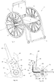
- An exemplifying wheelchair is depicted in Fig. 1 , wherein a wheelchair 1 essentially comprises a seat 2, a back 3, a foot support 4, and two wheels 5.
- Each of the two wheels 5 is provided with an outer gripping ring 6 and an internal gear-shift arrangement 7.
- Fig. 1 only one of the two gear-shift arrangements 7 is visible.
- the wheel 5 and the gripping ring 6 were fixedly connected to each other, the wheel 5 would rotate with the same rotational speed as the gripping ring 6. This means that when a user travels uphill or in rough terrain, the user must exercise a considerable force to be able to move the wheelchair 1 at all, whereas the user when traveling downhill or in flat and easy terrain cannot move his/her hands fast enough to travel as fast as his/her arm strength actually would allow him/her to do.
- the rotational speed of the wheel 5 can differ from the rotational speed of the gripping ring 6, thereby allowing a more efficient use of the user's strength when propelling the wheelchair 1. From Fig.
- the wheels 5 are slightly tilted inwards, towards the seat 2 and the back 3.
- the distance between the wheels 5 as measured at ground level is longer than the corresponding distance measured at top level.
- This inclination angle to an imaginary vertical line can, for example, be between one (1) degree and fifteen (15) degrees. To arrange for such an inclination of the wheelchair wheels 5 is particularly advantageous in combination with the different embodiments of the present invention, as will be demonstrated below.
- the gear-shift arrangement 7 comprises further an internal-gear hub 8 with a wheel axle (not visible in the figure) and a gear selector 9.
- the internal-gear hub 8 is preferably a planetary gear system, which is well-known in the art and will not be described in detail herein. Suitable planetary gear systems are, for example, described in the U.S. Patent No. 8,388,490 to Su et al. which relates to a fixed internal-gear hub. Suitable internal-gear hubs are, for example, commercially available from the company Sturmey-Archer, e.g. the model S3X.
- gear-shift arrangements where a common feature is that a gear selector extends essentially perpendicularly or radially to a wheel axle of a wheelchair wheel, which, in combination with an internal-gear hub, achieves the goal of minimizing the extra width that a gear-shift arrangement adds to the wheel and thereby to the wheelchair.
- Gear-shift arrangements according to the present invention are user-friendly and easy to operate, and require, for example, only a very small amount of force for shifting gears.
- gear-shift arrangements disclosed herein are further adapted to incorporate two, three or more gear positions.
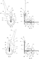
- Figs. 2a and 2b as well as Figs. 2c and 2d show a first embodiment of a gear-shift arrangement 10, which comprises a gear selector 11, which has a lower or inner base portion 12 and an upper or outer portion in the shape of a handle 13, a connector member 14, and a shift member 15.
- the shift member 15 is provided with a cogged portion 29 and is inside an internal-gear hub 16 having a wheel axle 17 axially moveable to engage gears 18, 18' and 18", respectively.
- the connector member 14 is in the form of a chain 19, which is attached to the shift member 15, and a pin 20, which is attached to a sliding element 21 in the shape of a spigot shaft 21 being provided with a distal securing washer 22 and whose proximal portion is provided with a holding washer 23.
- the spigot shaft 21 can slide in a vertical direction in a guide slot 24 provided in a guide member 25, and can further slide essentially circumferentially in a cam curve 26 provided in the base portion 12 of the gear selector 11.
- the cam curve 26 comprises three positions 27, 27' and 27", each of which corresponds to a respective gear 18, 18' or 18".
- the internal-gear hub 16 is further provided with a return spring 28, which facilitates gear shifting in one direction, i.e. to move shift member 15 to the right in Fig. 2b and Fig. 2d .
- spigot shaft 21 moves a comparatively long distance in the circumferential direction along and within cam curve 26
- spigot shaft 21 moves only a relatively short radial distance of cam curve 26 as well as of guide slot 24 in guide member 25 from the center, i.e. from the wheel axle 17.
- This has the advantageous effect that the force needed to shift gear is small in accordance with the well-known relation for the work carried out by applying a force along a path.
- guide member 25 and thereby guide slot 24 are always directed in a vertical direction. This has the advantageous effect that there is no twisting or turning of chain 19, which positively affects the operability of the gear-shift arrangement 10 as well as contributes to a long useful life of the system.
- the gear shift arrangement 10 does only add a minimal amount of extra width to a wheelchair wheel. This is in particular the case, if the wheelchair wheel is slightly tilted outwards towards the ground, since then the largest width of the wheelchair may still be at ground level.
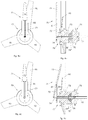
- Figs. 3a and 3b show a second embodiment of a gear-shift arrangement 40, which comprises a gear selector 41, which has a lower or inner base portion 42 and an upper or outer portion in the shape of a handle 43, a connector member 44, and a shift member 45.
- the shift member 45 is provided with a cogged portion 59 and is inside an internal-gear hub 46 having a wheel axle 47 axially moveable to engage gears 48, 48' and 48", respectively.
- the connector member 44 is in the form of a wire 49, which is attached to the shift member 45, and a sliding element 51 in the shape of a bent pin 51. As can be seen in Fig.
- a shaft portion 54 of the bent pin 51 extends in the radial direction and is attached to the wire 49 while the other end of the bent pin 51 is bent about 90 degrees and is slideably fitted in a cam curve 56 provided in the base portion 42 of the gear selector 41.
- the bent pin 51 is provided with two widenings 52 and 53, such that a distal widening 52 is provided on the inside of the cam curve 56 and a proximal widening 53 is provided on the outside of the cam curve 56.
- the cam curve 56 comprises three positions 57, 57' and 57", each of which corresponds to a respective gear 48, 48' or 48".
- spokes 60 are visible. Spokes 60 are attached to a gripping ring not seen in Figs. 3a and 3b .
- the gear-shift arrangement 40 works in all essentiality in the same way as gear-shift arrangement 10 described above in conjunction with Figs. 2a-2d . There are, however, a few notable differences that can be mentioned.
- the gear-shift arrangement 40 lacks a guide element, corresponding to guide member 25 of the first embodiment described above and which steers a sliding element or member, which in this case would be the bent pin 51 in a vertical direction.
- Such a guide element could be provided also for gear-shift arrangement 40, but it is believed that a wire, like wire 49, is rather insensitive to any twisting that could arise when the bent pin 51 travels in the cam curve 56.
- gear-shift arrangement 40 lacks a return mechanism, corresponding to return spring 28 of gear-shift arrangement 10; instead the wire 49 slides in a sleeve 58.
- gear-shift arrangement 40 comprises further a spring 61.
- This spring 61 can be regarded as a load accommodating spring 61, and it operates such that when a user has moved gear selector 41 and thereby shift member 45 in order to shift gears but the cogged portion 59 of shift member 45 cannot get in operative engagement with a selected one of the gears 48, 48' and 48", because the cogs on the selected one of gears 48, 48' and 48" are in the same angular positions as the cogs on the cogged portion 59, the load accommodating spring 61 is compressed (or extended depending on the gear-shift direction) and will execute the intended gear shifting as soon as gears 48, 48' and 48" have rotated a small angular distance such that the cogged portion 59 of the shift member 45 can get into operative engagement with the selected one of the gears 48, 48 and 48". Without the spring 61, the wear on the system will be higher.
- a cam curve is provided in a base portion of a gear selector.
- the base portion can occupy a circle sector ranging from about 10 degrees to about 90 degrees, and more preferably from about 20 degrees to about 50 degrees.
- the cam curve can be located at an average radial distance from the center, i.e. from the wheel axle, that ranges from 20 mm to 200 mm, and more preferably from 50 mm to 150 mm.
- the difference in radial distance for consecutive or neighbouring cam curve positions can range from about 1 mm to about 20 mm, preferably from about 3 mm to about 8 mm, while the difference in circumferential distance for consecutive or neighbouring cam curve positions can range from about 5 mm to about 30 mm, whereby it is advantageous that the circumferential distance is longer than the radial distance, as has been discussed above.
- a handle portion can have a length of about 80 mm to about 120 mm.
- Figs. 4a and 4b as well as Figs. 4c and 4d show a third embodiment of a gear-shift arrangement 70, which comprises a gear selector 71, which has a lower or inner base portion 72 and an upper or outer portion in the shape of a handle 73, a connector member 74, and a shift member 75.
- the shift member 75 is provided with a cogged portion 89 and is inside an internal-gear hub 76 having a wheel axle 77 axially moveable to engage gears 78, 78' and 78", respectively.
- the connector member 74 is in the form of an extension to shift member 75, and connector member 74 can, in fact, be regarded as an outer portion of shift member 75.
- the gear-shift arrangement 70 comprises further a holding member 85.
- the gear selector 71 is somewhere along its length attached to the holding member 85 by a pivot shaft 81, such that gear selector 71 can rotate around pivot shaft 81. Since the inner or lower end of gear selector 71 is attached to the connector member 74, and thereby directly to shift member 75, the gear selector 71 is actually a lever arm 71 having pivot shaft 81 as its pivot point. In Figs. 4a to 4d also spokes 90 are visible. Spokes 90 are attached to a gripping ring not seen in Figs. 4a to 4d .
- a user by gripping the handle or handle portion 73 and pushing handle portion 73 inwards towards a wheelchair wheel, such that the gear selector 71 or lever arm 71 rotates around pivot shaft 81 in a clockwise direction and base portion 72 moves outwards, the connector member 74 and thereby shift member 75 is pulled outwards which causes the cogged portion 89 of shift member 75 to move from engagement with gear 78 into engagement with gear 78".
- the pivot shaft 81 can be placed such that the length of the base portion 72 of lever arm 71 is shorter than the length of the handle portion 73, which has the advantageous effect that the force needed to shift gear is small in accordance with the well-known lever principle.
- the total length of a lever arm can range from about 100 mm to about 300 mm and more preferably from about 150 mm to about 200 mm, while the length of a base portion preferably constitutes from about 10 % to about 50 % of the total lever arm length.
- gear selector and a holding member can occupy a circle sector ranging from about 10 degrees to about 20 degrees.
- a common feature of all gear-shift arrangements presented herein is that a gear selector and any existing guiding or holding members do not rotate as a user propels a wheelchair. It is therefore easy for a user to locate the gear selector when he or she wants to shift gear in order to change the rotational speed of a gripping ring in relation to the rotational speed of adjoining wheelchair wheel.
Landscapes
- Health & Medical Sciences (AREA)
- Life Sciences & Earth Sciences (AREA)
- Animal Behavior & Ethology (AREA)
- General Health & Medical Sciences (AREA)
- Public Health (AREA)
- Veterinary Medicine (AREA)
- Engineering & Computer Science (AREA)
- Chemical & Material Sciences (AREA)
- Combustion & Propulsion (AREA)
- Transportation (AREA)
- Mechanical Engineering (AREA)
- Gear-Shifting Mechanisms (AREA)
Claims (8)
- Ensemble roue comprenant une roue (5) pour un fauteuil roulant (1), une bague de serrage (6) raccordée à la roue, et un agencement de changement de vitesse (7 ; 10 ; 40 ; 70) ;
la roue étant fournie avec un axe de roue (17 ; 47 ; 77) ; l'agencement de changement de vitesse étant configuré pour changer le rapport de vitesse entre la roue et la bague de serrage ;
l'agencement de changement de vitesse comprenant :- un moyeu de vitesse interne (8 ; 16 ; 46 ; 76) comprenant un certain nombre de vitesses internes (18, 18', 18" ; 48, 48', 48" ; 78, 78', 78"),- un élément de changement (15 ; 45 ; 75), et- un sélecteur de vitesse (9 ; 11 ; 41 ; 71) ;dans lequel le sélecteur de vitesse et la bague de serrage sont situés sur le même côté de la roue ;
caractérisé en ce que le sélecteur de vitesse est raccordé de manière opérationnelle à l'élément de changement, qui est axialement amovible à l'intérieur du moyeu de vitesse interne pour mettre en prise une vitesse spécifique dudit nombre de vitesses internes, et en ce que le sélecteur de vitesse présente une partie de base intérieure (12 ; 42 ; 72) et une partie poignée extérieure (13 ; 43 ; 73) et s'étend radialement à distance de l'axe de roue. - Ensemble roue selon la revendication 1, dans lequel le sélecteur de vitesse occupe un secteur circulaire.
- Ensemble roue selon la revendication 1 ou la revendication 2, dans lequel la partie de base (12 ; 42) de l'agencement de changement de vitesse (10 ; 40) comprend une courbe de came (26 ; 56) présentant un certain nombre de positions fixes (27, 27', 27" ; 57, 57', 57") à l'intérieur, et dans lequel l'élément de changement (15 ; 45), par l'intermédiaire d'un élément de raccordement (14, 44), est raccordé à un élément coulissant (21, 51) qui peut coulisser dans la courbe de came et être positionné dans une position fixe par un utilisateur serrant et déplaçant la partie poignée dans une direction circonférentielle.
- Ensemble roue selon la revendication 3, dans lequel les positions fixes avoisinantes de la courbe de came sont espacées à la fois par une distance circonférentielle et une distance radiale, la distance circonférentielle étant supérieure à la distance radiale.
- Ensemble roue selon la revendication 3 ou la revendication 4, dans lequel l'élément de raccordement (14) de l'agencement de changement de vitesse est sous la forme d'une chaîne (19).
- Ensemble roue selon la revendication 3 ou la revendication 4, dans lequel l'élément de raccordement (44) de l'agencement de changement de vitesse est sous la forme d'un câble (49) .
- Ensemble roue selon la revendication 1, dans lequel le sélecteur de vitesse (71) de l'agencement de changement de vitesse (70) est fixé de manière rotative à un arbre de pivot (81) fourni dans un élément de maintien (85) s'étendant en relation étroite vers le sélecteur de vitesse, de sorte que le sélecteur de vitesse constitue un bras de levier dont l'extrémité inférieure est raccordée à l'élément de changement (75) .
- Ensemble roue selon la revendication 7, dans lequel l'arbre de pivot (81) divise le sélecteur de vitesse (71) en la partie de base intérieure (72) et la partie de base extérieure (73), et la partie de base intérieure est plus courte que la partie de base extérieure.
Applications Claiming Priority (2)
| Application Number | Priority Date | Filing Date | Title |
|---|---|---|---|
| SE1450512A SE538008C2 (sv) | 2014-04-30 | 2014-04-30 | Växelanordning för ett rullstolshjul |
| PCT/SE2015/050421 WO2015167387A1 (fr) | 2014-04-30 | 2015-04-09 | Agencement de changement de vitesse pour roue de fauteuil roulant |
Publications (3)
| Publication Number | Publication Date |
|---|---|
| EP3137032A1 EP3137032A1 (fr) | 2017-03-08 |
| EP3137032A4 EP3137032A4 (fr) | 2017-11-01 |
| EP3137032B1 true EP3137032B1 (fr) | 2018-12-26 |
Family
ID=54358968
Family Applications (1)
| Application Number | Title | Priority Date | Filing Date |
|---|---|---|---|
| EP15786312.7A Not-in-force EP3137032B1 (fr) | 2014-04-30 | 2015-04-09 | Agencement de changement de vitesse pour roue de fauteuil roulant |
Country Status (4)
| Country | Link |
|---|---|
| US (1) | US10179076B2 (fr) |
| EP (1) | EP3137032B1 (fr) |
| SE (1) | SE538008C2 (fr) |
| WO (1) | WO2015167387A1 (fr) |
Families Citing this family (3)
| Publication number | Priority date | Publication date | Assignee | Title |
|---|---|---|---|---|
| EP3500223B1 (fr) | 2016-08-17 | 2020-04-22 | GearWheel AB | Agencement de butée arrière et de changement de vitesse pour roue de fauteuil roulant |
| JP6742493B1 (ja) * | 2019-11-29 | 2020-08-19 | 合同会社ライフスペース研究所 | 片手操作可能な車椅子 |
| AU2023366636A1 (en) * | 2022-10-26 | 2025-06-12 | Claire Lorraine Flemmer | A wheel assembly for a manual wheelchair |
Family Cites Families (19)
| Publication number | Priority date | Publication date | Assignee | Title |
|---|---|---|---|---|
| DE2337725C2 (de) * | 1973-07-25 | 1983-01-05 | Fichtel & Sachs Ag, 8720 Schweinfurt | Mehrgang-Nabe mit Rücktritt-Bremseinrichtung |
| US4069725A (en) * | 1975-01-07 | 1978-01-24 | Shimano Industrial Company Limited | Three speed transmission hub |
| DE3340407A1 (de) * | 1983-11-09 | 1985-06-27 | Sanitätshaus Heinrich Oesterreich GmbH, 2800 Bremen | Krankenfahrstuhl |
| US5362081A (en) | 1993-03-10 | 1994-11-08 | Beidler Michael T | Wheelchair drive system |
| CA2095681A1 (fr) * | 1993-05-06 | 1994-11-07 | Gary Godin | Roue de fauteuil roulant a moyeu de changement de vitesse |
| US5482305A (en) | 1995-01-06 | 1996-01-09 | University Of Washington | Shifting mechanism and quick release for multispeed wheelchair |
| US6017046A (en) * | 1998-01-21 | 2000-01-25 | Markovic; Vladimir | Wheelchair apparatus |
| US6117040A (en) * | 1999-04-12 | 2000-09-12 | 792049 Alberta Ltd. | Multi-speed wheel hub for automotive vehicles |
| US6428028B1 (en) * | 1999-12-06 | 2002-08-06 | Synkinetics, Inc. | Wheel transmission for mobility vehicle |
| CA2350263C (fr) * | 2001-06-12 | 2006-09-05 | Dt Planetaries Inc. | Moyeu de roue a plusieurs vitesses pour vehicules automobiles |
| US6805371B2 (en) | 2001-09-14 | 2004-10-19 | Magic Wheels, Inc | Two-speed wheel assembly for manual wheelchairs, with a quick-release mounting capability |
| US8109529B2 (en) * | 2005-08-01 | 2012-02-07 | Rand Ethan | Ergonomic wheelchair propulsion system |
| SE530021C2 (sv) | 2006-06-16 | 2008-02-12 | Gearwheel Ab | Växelförare vid ett nav hos ett hjul med snabblåsningsfunktion och metod för att ändra utväxling mellan en drivanordning och ett hjul hos ett fordon |
| US7837210B2 (en) * | 2007-03-31 | 2010-11-23 | Daedalus Wings, Inc. | Wheelchair drive system with lever propulsion and a hub-contained transmission |
| US7520519B2 (en) * | 2007-04-10 | 2009-04-21 | Smurthwaite Jr William J | Manually driven wheelchair |
| ITUD20070101A1 (it) * | 2007-05-31 | 2008-12-01 | Aniello Langella | Sedia a rotelle |
| TW201024577A (en) | 2008-12-24 | 2010-07-01 | Sunrace Roots Entpr Co Ltd | Stationary transmission inner derailleur |
| CN103429210A (zh) | 2011-02-03 | 2013-12-04 | 吉尔威尔股份公司 | 轮椅轮附装和换挡适配器单元 |
| GB201106805D0 (en) | 2011-04-21 | 2011-06-01 | Folding Attic Stairs Ltd | A wheelchair drive mechanism |
-
2014
- 2014-04-30 SE SE1450512A patent/SE538008C2/sv not_active IP Right Cessation
-
2015
- 2015-04-09 WO PCT/SE2015/050421 patent/WO2015167387A1/fr not_active Ceased
- 2015-04-09 EP EP15786312.7A patent/EP3137032B1/fr not_active Not-in-force
- 2015-04-09 US US15/306,893 patent/US10179076B2/en active Active
Non-Patent Citations (1)
| Title |
|---|
| None * |
Also Published As
| Publication number | Publication date |
|---|---|
| WO2015167387A1 (fr) | 2015-11-05 |
| US20170049644A1 (en) | 2017-02-23 |
| EP3137032A1 (fr) | 2017-03-08 |
| SE538008C2 (sv) | 2016-02-09 |
| US10179076B2 (en) | 2019-01-15 |
| EP3137032A4 (fr) | 2017-11-01 |
| SE1450512A1 (sv) | 2015-10-31 |
Similar Documents
| Publication | Publication Date | Title |
|---|---|---|
| US8061233B2 (en) | Actuation method and device for a control cable for a bicycle gearshift | |
| US20080252036A1 (en) | Manually driven wheelchair | |
| EP2683602B1 (fr) | Système à engrenages à plusieurs vitesses | |
| US5967937A (en) | Motorized shift assist control apparatus for bicycle transmission | |
| JP6374903B2 (ja) | 自転車用変速機 | |
| US4682784A (en) | Wheelchair with variable ratio propulsion | |
| CN108688771A (zh) | 自行车后变速器 | |
| JP6675110B2 (ja) | 駆動ユニットおよび電動アシスト自転車 | |
| CN102556279B (zh) | 用于自行车换档机构用控制线缆的致动装置 | |
| US10179076B2 (en) | Gear-shift arrangement for a wheelchair wheel | |
| JPS6328838B2 (fr) | ||
| CN120916940A (zh) | 自行车变速器系统 | |
| US20170227096A1 (en) | Variable ratio crankshaft transmission | |
| US4583754A (en) | Transmission unit | |
| TWI732873B (zh) | 自行車換檔的控制線的致動裝置 | |
| US8357071B2 (en) | Planetary gear mechanism for a bicycle internal hub transmission | |
| SE530021C2 (sv) | Växelförare vid ett nav hos ett hjul med snabblåsningsfunktion och metod för att ändra utväxling mellan en drivanordning och ett hjul hos ett fordon | |
| US20090206574A1 (en) | Lever Drive Wheelchair Transmission | |
| JP4874388B2 (ja) | 可変速ダイレクトドライブ式伝動装置 | |
| WO2002008637A2 (fr) | Transmission mecanique variable en continu | |
| US8220357B2 (en) | Bicycle shifter | |
| CN120936541A (zh) | 自行车变速器 | |
| US6796200B2 (en) | Multi speed bicycle transmission including eccentric cranking assembly | |
| US4056013A (en) | Bicycle transmissions | |
| EP3257737B1 (fr) | Variateur de vitesse pour une bicyclette |
Legal Events
| Date | Code | Title | Description |
|---|---|---|---|
| STAA | Information on the status of an ep patent application or granted ep patent |
Free format text: STATUS: THE INTERNATIONAL PUBLICATION HAS BEEN MADE |
|
| PUAI | Public reference made under article 153(3) epc to a published international application that has entered the european phase |
Free format text: ORIGINAL CODE: 0009012 |
|
| STAA | Information on the status of an ep patent application or granted ep patent |
Free format text: STATUS: REQUEST FOR EXAMINATION WAS MADE |
|
| 17P | Request for examination filed |
Effective date: 20161118 |
|
| AK | Designated contracting states |
Kind code of ref document: A1 Designated state(s): AL AT BE BG CH CY CZ DE DK EE ES FI FR GB GR HR HU IE IS IT LI LT LU LV MC MK MT NL NO PL PT RO RS SE SI SK SM TR |
|
| AX | Request for extension of the european patent |
Extension state: BA ME |
|
| DAV | Request for validation of the european patent (deleted) | ||
| DAX | Request for extension of the european patent (deleted) | ||
| A4 | Supplementary search report drawn up and despatched |
Effective date: 20171005 |
|
| RIC1 | Information provided on ipc code assigned before grant |
Ipc: A61G 5/02 20060101AFI20170928BHEP Ipc: A61G 5/10 20060101ALI20170928BHEP Ipc: B62M 1/16 20060101ALI20170928BHEP Ipc: B62M 1/14 20060101ALI20170928BHEP |
|
| GRAP | Despatch of communication of intention to grant a patent |
Free format text: ORIGINAL CODE: EPIDOSNIGR1 |
|
| STAA | Information on the status of an ep patent application or granted ep patent |
Free format text: STATUS: GRANT OF PATENT IS INTENDED |
|
| RAP1 | Party data changed (applicant data changed or rights of an application transferred) |
Owner name: GEARWHEEL AB |
|
| INTG | Intention to grant announced |
Effective date: 20181009 |
|
| GRAS | Grant fee paid |
Free format text: ORIGINAL CODE: EPIDOSNIGR3 |
|
| GRAA | (expected) grant |
Free format text: ORIGINAL CODE: 0009210 |
|
| STAA | Information on the status of an ep patent application or granted ep patent |
Free format text: STATUS: THE PATENT HAS BEEN GRANTED |
|
| AK | Designated contracting states |
Kind code of ref document: B1 Designated state(s): AL AT BE BG CH CY CZ DE DK EE ES FI FR GB GR HR HU IE IS IT LI LT LU LV MC MK MT NL NO PL PT RO RS SE SI SK SM TR |
|
| REG | Reference to a national code |
Ref country code: GB Ref legal event code: FG4D |
|
| REG | Reference to a national code |
Ref country code: CH Ref legal event code: EP |
|
| REG | Reference to a national code |
Ref country code: AT Ref legal event code: REF Ref document number: 1080407 Country of ref document: AT Kind code of ref document: T Effective date: 20190115 |
|
| REG | Reference to a national code |
Ref country code: DE Ref legal event code: R096 Ref document number: 602015022432 Country of ref document: DE |
|
| REG | Reference to a national code |
Ref country code: IE Ref legal event code: FG4D |
|
| PG25 | Lapsed in a contracting state [announced via postgrant information from national office to epo] |
Ref country code: FI Free format text: LAPSE BECAUSE OF FAILURE TO SUBMIT A TRANSLATION OF THE DESCRIPTION OR TO PAY THE FEE WITHIN THE PRESCRIBED TIME-LIMIT Effective date: 20181226 Ref country code: LT Free format text: LAPSE BECAUSE OF FAILURE TO SUBMIT A TRANSLATION OF THE DESCRIPTION OR TO PAY THE FEE WITHIN THE PRESCRIBED TIME-LIMIT Effective date: 20181226 Ref country code: HR Free format text: LAPSE BECAUSE OF FAILURE TO SUBMIT A TRANSLATION OF THE DESCRIPTION OR TO PAY THE FEE WITHIN THE PRESCRIBED TIME-LIMIT Effective date: 20181226 Ref country code: LV Free format text: LAPSE BECAUSE OF FAILURE TO SUBMIT A TRANSLATION OF THE DESCRIPTION OR TO PAY THE FEE WITHIN THE PRESCRIBED TIME-LIMIT Effective date: 20181226 Ref country code: NO Free format text: LAPSE BECAUSE OF FAILURE TO SUBMIT A TRANSLATION OF THE DESCRIPTION OR TO PAY THE FEE WITHIN THE PRESCRIBED TIME-LIMIT Effective date: 20190326 Ref country code: BG Free format text: LAPSE BECAUSE OF FAILURE TO SUBMIT A TRANSLATION OF THE DESCRIPTION OR TO PAY THE FEE WITHIN THE PRESCRIBED TIME-LIMIT Effective date: 20190326 |
|
| REG | Reference to a national code |
Ref country code: NL Ref legal event code: FP |
|
| REG | Reference to a national code |
Ref country code: LT Ref legal event code: MG4D |
|
| PG25 | Lapsed in a contracting state [announced via postgrant information from national office to epo] |
Ref country code: AL Free format text: LAPSE BECAUSE OF FAILURE TO SUBMIT A TRANSLATION OF THE DESCRIPTION OR TO PAY THE FEE WITHIN THE PRESCRIBED TIME-LIMIT Effective date: 20181226 Ref country code: SE Free format text: LAPSE BECAUSE OF FAILURE TO SUBMIT A TRANSLATION OF THE DESCRIPTION OR TO PAY THE FEE WITHIN THE PRESCRIBED TIME-LIMIT Effective date: 20181226 Ref country code: GR Free format text: LAPSE BECAUSE OF FAILURE TO SUBMIT A TRANSLATION OF THE DESCRIPTION OR TO PAY THE FEE WITHIN THE PRESCRIBED TIME-LIMIT Effective date: 20190327 Ref country code: RS Free format text: LAPSE BECAUSE OF FAILURE TO SUBMIT A TRANSLATION OF THE DESCRIPTION OR TO PAY THE FEE WITHIN THE PRESCRIBED TIME-LIMIT Effective date: 20181226 |
|
| REG | Reference to a national code |
Ref country code: AT Ref legal event code: MK05 Ref document number: 1080407 Country of ref document: AT Kind code of ref document: T Effective date: 20181226 |
|
| PG25 | Lapsed in a contracting state [announced via postgrant information from national office to epo] |
Ref country code: PT Free format text: LAPSE BECAUSE OF FAILURE TO SUBMIT A TRANSLATION OF THE DESCRIPTION OR TO PAY THE FEE WITHIN THE PRESCRIBED TIME-LIMIT Effective date: 20190426 Ref country code: CZ Free format text: LAPSE BECAUSE OF FAILURE TO SUBMIT A TRANSLATION OF THE DESCRIPTION OR TO PAY THE FEE WITHIN THE PRESCRIBED TIME-LIMIT Effective date: 20181226 Ref country code: ES Free format text: LAPSE BECAUSE OF FAILURE TO SUBMIT A TRANSLATION OF THE DESCRIPTION OR TO PAY THE FEE WITHIN THE PRESCRIBED TIME-LIMIT Effective date: 20181226 Ref country code: PL Free format text: LAPSE BECAUSE OF FAILURE TO SUBMIT A TRANSLATION OF THE DESCRIPTION OR TO PAY THE FEE WITHIN THE PRESCRIBED TIME-LIMIT Effective date: 20181226 Ref country code: IT Free format text: LAPSE BECAUSE OF FAILURE TO SUBMIT A TRANSLATION OF THE DESCRIPTION OR TO PAY THE FEE WITHIN THE PRESCRIBED TIME-LIMIT Effective date: 20181226 |
|
| PG25 | Lapsed in a contracting state [announced via postgrant information from national office to epo] |
Ref country code: SK Free format text: LAPSE BECAUSE OF FAILURE TO SUBMIT A TRANSLATION OF THE DESCRIPTION OR TO PAY THE FEE WITHIN THE PRESCRIBED TIME-LIMIT Effective date: 20181226 Ref country code: IS Free format text: LAPSE BECAUSE OF FAILURE TO SUBMIT A TRANSLATION OF THE DESCRIPTION OR TO PAY THE FEE WITHIN THE PRESCRIBED TIME-LIMIT Effective date: 20190426 Ref country code: RO Free format text: LAPSE BECAUSE OF FAILURE TO SUBMIT A TRANSLATION OF THE DESCRIPTION OR TO PAY THE FEE WITHIN THE PRESCRIBED TIME-LIMIT Effective date: 20181226 Ref country code: EE Free format text: LAPSE BECAUSE OF FAILURE TO SUBMIT A TRANSLATION OF THE DESCRIPTION OR TO PAY THE FEE WITHIN THE PRESCRIBED TIME-LIMIT Effective date: 20181226 Ref country code: SM Free format text: LAPSE BECAUSE OF FAILURE TO SUBMIT A TRANSLATION OF THE DESCRIPTION OR TO PAY THE FEE WITHIN THE PRESCRIBED TIME-LIMIT Effective date: 20181226 |
|
| REG | Reference to a national code |
Ref country code: DE Ref legal event code: R097 Ref document number: 602015022432 Country of ref document: DE |
|
| PG25 | Lapsed in a contracting state [announced via postgrant information from national office to epo] |
Ref country code: AT Free format text: LAPSE BECAUSE OF FAILURE TO SUBMIT A TRANSLATION OF THE DESCRIPTION OR TO PAY THE FEE WITHIN THE PRESCRIBED TIME-LIMIT Effective date: 20181226 Ref country code: DK Free format text: LAPSE BECAUSE OF FAILURE TO SUBMIT A TRANSLATION OF THE DESCRIPTION OR TO PAY THE FEE WITHIN THE PRESCRIBED TIME-LIMIT Effective date: 20181226 |
|
| PLBE | No opposition filed within time limit |
Free format text: ORIGINAL CODE: 0009261 |
|
| STAA | Information on the status of an ep patent application or granted ep patent |
Free format text: STATUS: NO OPPOSITION FILED WITHIN TIME LIMIT |
|
| 26N | No opposition filed |
Effective date: 20190927 |
|
| REG | Reference to a national code |
Ref country code: BE Ref legal event code: MM Effective date: 20190430 |
|
| PG25 | Lapsed in a contracting state [announced via postgrant information from national office to epo] |
Ref country code: MC Free format text: LAPSE BECAUSE OF FAILURE TO SUBMIT A TRANSLATION OF THE DESCRIPTION OR TO PAY THE FEE WITHIN THE PRESCRIBED TIME-LIMIT Effective date: 20181226 Ref country code: LU Free format text: LAPSE BECAUSE OF NON-PAYMENT OF DUE FEES Effective date: 20190409 |
|
| PG25 | Lapsed in a contracting state [announced via postgrant information from national office to epo] |
Ref country code: BE Free format text: LAPSE BECAUSE OF NON-PAYMENT OF DUE FEES Effective date: 20190430 Ref country code: SI Free format text: LAPSE BECAUSE OF FAILURE TO SUBMIT A TRANSLATION OF THE DESCRIPTION OR TO PAY THE FEE WITHIN THE PRESCRIBED TIME-LIMIT Effective date: 20181226 |
|
| PG25 | Lapsed in a contracting state [announced via postgrant information from national office to epo] |
Ref country code: TR Free format text: LAPSE BECAUSE OF FAILURE TO SUBMIT A TRANSLATION OF THE DESCRIPTION OR TO PAY THE FEE WITHIN THE PRESCRIBED TIME-LIMIT Effective date: 20181226 |
|
| PG25 | Lapsed in a contracting state [announced via postgrant information from national office to epo] |
Ref country code: IE Free format text: LAPSE BECAUSE OF NON-PAYMENT OF DUE FEES Effective date: 20190409 |
|
| PG25 | Lapsed in a contracting state [announced via postgrant information from national office to epo] |
Ref country code: CY Free format text: LAPSE BECAUSE OF FAILURE TO SUBMIT A TRANSLATION OF THE DESCRIPTION OR TO PAY THE FEE WITHIN THE PRESCRIBED TIME-LIMIT Effective date: 20181226 |
|
| PG25 | Lapsed in a contracting state [announced via postgrant information from national office to epo] |
Ref country code: HU Free format text: LAPSE BECAUSE OF FAILURE TO SUBMIT A TRANSLATION OF THE DESCRIPTION OR TO PAY THE FEE WITHIN THE PRESCRIBED TIME-LIMIT; INVALID AB INITIO Effective date: 20150409 Ref country code: MT Free format text: LAPSE BECAUSE OF FAILURE TO SUBMIT A TRANSLATION OF THE DESCRIPTION OR TO PAY THE FEE WITHIN THE PRESCRIBED TIME-LIMIT Effective date: 20181226 |
|
| PG25 | Lapsed in a contracting state [announced via postgrant information from national office to epo] |
Ref country code: MK Free format text: LAPSE BECAUSE OF FAILURE TO SUBMIT A TRANSLATION OF THE DESCRIPTION OR TO PAY THE FEE WITHIN THE PRESCRIBED TIME-LIMIT Effective date: 20181226 |
|
| PGFP | Annual fee paid to national office [announced via postgrant information from national office to epo] |
Ref country code: NL Payment date: 20220421 Year of fee payment: 8 |
|
| PGFP | Annual fee paid to national office [announced via postgrant information from national office to epo] |
Ref country code: GB Payment date: 20220421 Year of fee payment: 8 Ref country code: FR Payment date: 20220414 Year of fee payment: 8 Ref country code: DE Payment date: 20220422 Year of fee payment: 8 |
|
| PGFP | Annual fee paid to national office [announced via postgrant information from national office to epo] |
Ref country code: CH Payment date: 20220419 Year of fee payment: 8 |
|
| REG | Reference to a national code |
Ref country code: DE Ref legal event code: R119 Ref document number: 602015022432 Country of ref document: DE |
|
| REG | Reference to a national code |
Ref country code: CH Ref legal event code: PL |
|
| REG | Reference to a national code |
Ref country code: NL Ref legal event code: MM Effective date: 20230501 |
|
| GBPC | Gb: european patent ceased through non-payment of renewal fee |
Effective date: 20230409 |
|
| PG25 | Lapsed in a contracting state [announced via postgrant information from national office to epo] |
Ref country code: GB Free format text: LAPSE BECAUSE OF NON-PAYMENT OF DUE FEES Effective date: 20230409 |
|
| PG25 | Lapsed in a contracting state [announced via postgrant information from national office to epo] |
Ref country code: NL Free format text: LAPSE BECAUSE OF NON-PAYMENT OF DUE FEES Effective date: 20230501 Ref country code: LI Free format text: LAPSE BECAUSE OF NON-PAYMENT OF DUE FEES Effective date: 20230430 Ref country code: GB Free format text: LAPSE BECAUSE OF NON-PAYMENT OF DUE FEES Effective date: 20230409 Ref country code: FR Free format text: LAPSE BECAUSE OF NON-PAYMENT OF DUE FEES Effective date: 20230430 Ref country code: DE Free format text: LAPSE BECAUSE OF NON-PAYMENT OF DUE FEES Effective date: 20231103 Ref country code: CH Free format text: LAPSE BECAUSE OF NON-PAYMENT OF DUE FEES Effective date: 20230430 |