EP3137382B1 - Verfahren und vorrichtung zum thermischen aktivieren von verpackungsmänteln - Google Patents
Verfahren und vorrichtung zum thermischen aktivieren von verpackungsmänteln Download PDFInfo
- Publication number
- EP3137382B1 EP3137382B1 EP15722467.6A EP15722467A EP3137382B1 EP 3137382 B1 EP3137382 B1 EP 3137382B1 EP 15722467 A EP15722467 A EP 15722467A EP 3137382 B1 EP3137382 B1 EP 3137382B1
- Authority
- EP
- European Patent Office
- Prior art keywords
- tube
- shaped packaging
- packaging
- packaging sleeve
- inner part
- Prior art date
- Legal status (The legal status is an assumption and is not a legal conclusion. Google has not performed a legal analysis and makes no representation as to the accuracy of the status listed.)
- Not-in-force
Links
- 238000004806 packaging method and process Methods 0.000 title claims description 68
- 238000000034 method Methods 0.000 title claims description 9
- 230000003213 activating effect Effects 0.000 title description 6
- 238000001994 activation Methods 0.000 claims description 17
- 238000010438 heat treatment Methods 0.000 claims description 17
- 239000002131 composite material Substances 0.000 claims description 15
- 239000004033 plastic Substances 0.000 claims description 9
- 229920003023 plastic Polymers 0.000 claims description 9
- 230000004913 activation Effects 0.000 claims description 8
- 235000021056 liquid food Nutrition 0.000 claims description 5
- 238000007725 thermal activation Methods 0.000 claims 2
- 238000007493 shaping process Methods 0.000 claims 1
- 239000007789 gas Substances 0.000 description 14
- 239000010410 layer Substances 0.000 description 6
- 238000004519 manufacturing process Methods 0.000 description 6
- 238000007789 sealing Methods 0.000 description 5
- 239000004698 Polyethylene Substances 0.000 description 3
- 235000013361 beverage Nutrition 0.000 description 2
- 239000005022 packaging material Substances 0.000 description 2
- 238000003825 pressing Methods 0.000 description 2
- 229920000219 Ethylene vinyl alcohol Polymers 0.000 description 1
- 239000012790 adhesive layer Substances 0.000 description 1
- XAGFODPZIPBFFR-UHFFFAOYSA-N aluminium Chemical compound [Al] XAGFODPZIPBFFR-UHFFFAOYSA-N 0.000 description 1
- 229910052782 aluminium Inorganic materials 0.000 description 1
- QVGXLLKOCUKJST-UHFFFAOYSA-N atomic oxygen Chemical compound [O] QVGXLLKOCUKJST-UHFFFAOYSA-N 0.000 description 1
- 230000004888 barrier function Effects 0.000 description 1
- 239000012876 carrier material Substances 0.000 description 1
- 238000010276 construction Methods 0.000 description 1
- 238000013461 design Methods 0.000 description 1
- 238000009826 distribution Methods 0.000 description 1
- 210000005069 ears Anatomy 0.000 description 1
- UFRKOOWSQGXVKV-UHFFFAOYSA-N ethene;ethenol Chemical compound C=C.OC=C UFRKOOWSQGXVKV-UHFFFAOYSA-N 0.000 description 1
- 239000004715 ethylene vinyl alcohol Substances 0.000 description 1
- 230000002349 favourable effect Effects 0.000 description 1
- 210000003608 fece Anatomy 0.000 description 1
- 239000011888 foil Substances 0.000 description 1
- 238000003780 insertion Methods 0.000 description 1
- 230000037431 insertion Effects 0.000 description 1
- 239000002650 laminated plastic Substances 0.000 description 1
- 239000010871 livestock manure Substances 0.000 description 1
- 239000000463 material Substances 0.000 description 1
- 238000013021 overheating Methods 0.000 description 1
- 239000001301 oxygen Substances 0.000 description 1
- 229910052760 oxygen Inorganic materials 0.000 description 1
- 238000012856 packing Methods 0.000 description 1
- 238000012545 processing Methods 0.000 description 1
- 239000000758 substrate Substances 0.000 description 1
Images



Classifications
-
- B—PERFORMING OPERATIONS; TRANSPORTING
- B31—MAKING ARTICLES OF PAPER, CARDBOARD OR MATERIAL WORKED IN A MANNER ANALOGOUS TO PAPER; WORKING PAPER, CARDBOARD OR MATERIAL WORKED IN A MANNER ANALOGOUS TO PAPER
- B31B—MAKING CONTAINERS OF PAPER, CARDBOARD OR MATERIAL WORKED IN A MANNER ANALOGOUS TO PAPER
- B31B50/00—Making rigid or semi-rigid containers, e.g. boxes or cartons
- B31B50/60—Uniting opposed surfaces or edges; Taping
- B31B50/64—Uniting opposed surfaces or edges; Taping by applying heat or pressure, e.g. by welding
-
- B—PERFORMING OPERATIONS; TRANSPORTING
- B29—WORKING OF PLASTICS; WORKING OF SUBSTANCES IN A PLASTIC STATE IN GENERAL
- B29C—SHAPING OR JOINING OF PLASTICS; SHAPING OF MATERIAL IN A PLASTIC STATE, NOT OTHERWISE PROVIDED FOR; AFTER-TREATMENT OF THE SHAPED PRODUCTS, e.g. REPAIRING
- B29C65/00—Joining or sealing of preformed parts, e.g. welding of plastics materials; Apparatus therefor
- B29C65/02—Joining or sealing of preformed parts, e.g. welding of plastics materials; Apparatus therefor by heating, with or without pressure
- B29C65/10—Joining or sealing of preformed parts, e.g. welding of plastics materials; Apparatus therefor by heating, with or without pressure using hot gases (e.g. combustion gases) or flames coming in contact with at least one of the parts to be joined
- B29C65/103—Joining or sealing of preformed parts, e.g. welding of plastics materials; Apparatus therefor by heating, with or without pressure using hot gases (e.g. combustion gases) or flames coming in contact with at least one of the parts to be joined direct heating both surfaces to be joined
-
- B—PERFORMING OPERATIONS; TRANSPORTING
- B29—WORKING OF PLASTICS; WORKING OF SUBSTANCES IN A PLASTIC STATE IN GENERAL
- B29C—SHAPING OR JOINING OF PLASTICS; SHAPING OF MATERIAL IN A PLASTIC STATE, NOT OTHERWISE PROVIDED FOR; AFTER-TREATMENT OF THE SHAPED PRODUCTS, e.g. REPAIRING
- B29C66/00—General aspects of processes or apparatus for joining preformed parts
- B29C66/40—General aspects of joining substantially flat articles, e.g. plates, sheets or web-like materials; Making flat seams in tubular or hollow articles; Joining single elements to substantially flat surfaces
- B29C66/41—Joining substantially flat articles ; Making flat seams in tubular or hollow articles
- B29C66/43—Joining a relatively small portion of the surface of said articles
- B29C66/431—Joining the articles to themselves
- B29C66/4312—Joining the articles to themselves for making flat seams in tubular or hollow articles, e.g. transversal seams
- B29C66/43121—Closing the ends of tubular or hollow single articles, e.g. closing the ends of bags
- B29C66/43122—Closing the top of gable top containers
-
- B—PERFORMING OPERATIONS; TRANSPORTING
- B29—WORKING OF PLASTICS; WORKING OF SUBSTANCES IN A PLASTIC STATE IN GENERAL
- B29C—SHAPING OR JOINING OF PLASTICS; SHAPING OF MATERIAL IN A PLASTIC STATE, NOT OTHERWISE PROVIDED FOR; AFTER-TREATMENT OF THE SHAPED PRODUCTS, e.g. REPAIRING
- B29C66/00—General aspects of processes or apparatus for joining preformed parts
- B29C66/70—General aspects of processes or apparatus for joining preformed parts characterised by the composition, physical properties or the structure of the material of the parts to be joined; Joining with non-plastics material
- B29C66/72—General aspects of processes or apparatus for joining preformed parts characterised by the composition, physical properties or the structure of the material of the parts to be joined; Joining with non-plastics material characterised by the structure of the material of the parts to be joined
- B29C66/723—General aspects of processes or apparatus for joining preformed parts characterised by the composition, physical properties or the structure of the material of the parts to be joined; Joining with non-plastics material characterised by the structure of the material of the parts to be joined being multi-layered
- B29C66/7232—General aspects of processes or apparatus for joining preformed parts characterised by the composition, physical properties or the structure of the material of the parts to be joined; Joining with non-plastics material characterised by the structure of the material of the parts to be joined being multi-layered comprising a non-plastics layer
- B29C66/72327—General aspects of processes or apparatus for joining preformed parts characterised by the composition, physical properties or the structure of the material of the parts to be joined; Joining with non-plastics material characterised by the structure of the material of the parts to be joined being multi-layered comprising a non-plastics layer consisting of natural products or their composites, not provided for in B29C66/72321 - B29C66/72324
- B29C66/72328—Paper
-
- B—PERFORMING OPERATIONS; TRANSPORTING
- B29—WORKING OF PLASTICS; WORKING OF SUBSTANCES IN A PLASTIC STATE IN GENERAL
- B29C—SHAPING OR JOINING OF PLASTICS; SHAPING OF MATERIAL IN A PLASTIC STATE, NOT OTHERWISE PROVIDED FOR; AFTER-TREATMENT OF THE SHAPED PRODUCTS, e.g. REPAIRING
- B29C66/00—General aspects of processes or apparatus for joining preformed parts
- B29C66/80—General aspects of machine operations or constructions and parts thereof
- B29C66/81—General aspects of the pressing elements, i.e. the elements applying pressure on the parts to be joined in the area to be joined, e.g. the welding jaws or clamps
- B29C66/816—General aspects of the pressing elements, i.e. the elements applying pressure on the parts to be joined in the area to be joined, e.g. the welding jaws or clamps characterised by the mounting of the pressing elements, e.g. of the welding jaws or clamps
- B29C66/8167—Quick change joining tools or surfaces
-
- B—PERFORMING OPERATIONS; TRANSPORTING
- B29—WORKING OF PLASTICS; WORKING OF SUBSTANCES IN A PLASTIC STATE IN GENERAL
- B29C—SHAPING OR JOINING OF PLASTICS; SHAPING OF MATERIAL IN A PLASTIC STATE, NOT OTHERWISE PROVIDED FOR; AFTER-TREATMENT OF THE SHAPED PRODUCTS, e.g. REPAIRING
- B29C66/00—General aspects of processes or apparatus for joining preformed parts
- B29C66/90—Measuring or controlling the joining process
- B29C66/91—Measuring or controlling the joining process by measuring or controlling the temperature, the heat or the thermal flux
- B29C66/914—Measuring or controlling the joining process by measuring or controlling the temperature, the heat or the thermal flux by controlling or regulating the temperature, the heat or the thermal flux
- B29C66/9161—Measuring or controlling the joining process by measuring or controlling the temperature, the heat or the thermal flux by controlling or regulating the temperature, the heat or the thermal flux by controlling or regulating the heat or the thermal flux, i.e. the heat flux
-
- B—PERFORMING OPERATIONS; TRANSPORTING
- B31—MAKING ARTICLES OF PAPER, CARDBOARD OR MATERIAL WORKED IN A MANNER ANALOGOUS TO PAPER; WORKING PAPER, CARDBOARD OR MATERIAL WORKED IN A MANNER ANALOGOUS TO PAPER
- B31B—MAKING CONTAINERS OF PAPER, CARDBOARD OR MATERIAL WORKED IN A MANNER ANALOGOUS TO PAPER
- B31B50/00—Making rigid or semi-rigid containers, e.g. boxes or cartons
- B31B50/26—Folding sheets, blanks or webs
- B31B50/28—Folding sheets, blanks or webs around mandrels, e.g. for forming bottoms
-
- B—PERFORMING OPERATIONS; TRANSPORTING
- B65—CONVEYING; PACKING; STORING; HANDLING THIN OR FILAMENTARY MATERIAL
- B65B—MACHINES, APPARATUS OR DEVICES FOR, OR METHODS OF, PACKAGING ARTICLES OR MATERIALS; UNPACKING
- B65B51/00—Devices for, or methods of, sealing or securing package folds or closures; Devices for gathering or twisting wrappers, or necks of bags
- B65B51/10—Applying or generating heat or pressure or combinations thereof
- B65B51/20—Applying or generating heat or pressure or combinations thereof by fluid pressure acting directly on folds or on opposed surfaces, e.g. using hot-air jets
-
- B—PERFORMING OPERATIONS; TRANSPORTING
- B65—CONVEYING; PACKING; STORING; HANDLING THIN OR FILAMENTARY MATERIAL
- B65D—CONTAINERS FOR STORAGE OR TRANSPORT OF ARTICLES OR MATERIALS, e.g. BAGS, BARRELS, BOTTLES, BOXES, CANS, CARTONS, CRATES, DRUMS, JARS, TANKS, HOPPERS, FORWARDING CONTAINERS; ACCESSORIES, CLOSURES, OR FITTINGS THEREFOR; PACKAGING ELEMENTS; PACKAGES
- B65D59/00—Plugs, sleeves, caps, or like rigid or semi-rigid elements for protecting parts of articles or for bundling articles, e.g. protectors for screw-threads, end caps for tubes or for bundling rod-shaped articles
- B65D59/04—Sleeves, e.g. postal tubes
-
- B—PERFORMING OPERATIONS; TRANSPORTING
- B29—WORKING OF PLASTICS; WORKING OF SUBSTANCES IN A PLASTIC STATE IN GENERAL
- B29C—SHAPING OR JOINING OF PLASTICS; SHAPING OF MATERIAL IN A PLASTIC STATE, NOT OTHERWISE PROVIDED FOR; AFTER-TREATMENT OF THE SHAPED PRODUCTS, e.g. REPAIRING
- B29C66/00—General aspects of processes or apparatus for joining preformed parts
- B29C66/70—General aspects of processes or apparatus for joining preformed parts characterised by the composition, physical properties or the structure of the material of the parts to be joined; Joining with non-plastics material
- B29C66/71—General aspects of processes or apparatus for joining preformed parts characterised by the composition, physical properties or the structure of the material of the parts to be joined; Joining with non-plastics material characterised by the composition of the plastics material of the parts to be joined
-
- B—PERFORMING OPERATIONS; TRANSPORTING
- B29—WORKING OF PLASTICS; WORKING OF SUBSTANCES IN A PLASTIC STATE IN GENERAL
- B29C—SHAPING OR JOINING OF PLASTICS; SHAPING OF MATERIAL IN A PLASTIC STATE, NOT OTHERWISE PROVIDED FOR; AFTER-TREATMENT OF THE SHAPED PRODUCTS, e.g. REPAIRING
- B29C66/00—General aspects of processes or apparatus for joining preformed parts
- B29C66/70—General aspects of processes or apparatus for joining preformed parts characterised by the composition, physical properties or the structure of the material of the parts to be joined; Joining with non-plastics material
- B29C66/72—General aspects of processes or apparatus for joining preformed parts characterised by the composition, physical properties or the structure of the material of the parts to be joined; Joining with non-plastics material characterised by the structure of the material of the parts to be joined
- B29C66/723—General aspects of processes or apparatus for joining preformed parts characterised by the composition, physical properties or the structure of the material of the parts to be joined; Joining with non-plastics material characterised by the structure of the material of the parts to be joined being multi-layered
- B29C66/7232—General aspects of processes or apparatus for joining preformed parts characterised by the composition, physical properties or the structure of the material of the parts to be joined; Joining with non-plastics material characterised by the structure of the material of the parts to be joined being multi-layered comprising a non-plastics layer
- B29C66/72321—General aspects of processes or apparatus for joining preformed parts characterised by the composition, physical properties or the structure of the material of the parts to be joined; Joining with non-plastics material characterised by the structure of the material of the parts to be joined being multi-layered comprising a non-plastics layer consisting of metals or their alloys
-
- B—PERFORMING OPERATIONS; TRANSPORTING
- B29—WORKING OF PLASTICS; WORKING OF SUBSTANCES IN A PLASTIC STATE IN GENERAL
- B29C—SHAPING OR JOINING OF PLASTICS; SHAPING OF MATERIAL IN A PLASTIC STATE, NOT OTHERWISE PROVIDED FOR; AFTER-TREATMENT OF THE SHAPED PRODUCTS, e.g. REPAIRING
- B29C66/00—General aspects of processes or apparatus for joining preformed parts
- B29C66/70—General aspects of processes or apparatus for joining preformed parts characterised by the composition, physical properties or the structure of the material of the parts to be joined; Joining with non-plastics material
- B29C66/72—General aspects of processes or apparatus for joining preformed parts characterised by the composition, physical properties or the structure of the material of the parts to be joined; Joining with non-plastics material characterised by the structure of the material of the parts to be joined
- B29C66/723—General aspects of processes or apparatus for joining preformed parts characterised by the composition, physical properties or the structure of the material of the parts to be joined; Joining with non-plastics material characterised by the structure of the material of the parts to be joined being multi-layered
- B29C66/7234—General aspects of processes or apparatus for joining preformed parts characterised by the composition, physical properties or the structure of the material of the parts to be joined; Joining with non-plastics material characterised by the structure of the material of the parts to be joined being multi-layered comprising a barrier layer
-
- B—PERFORMING OPERATIONS; TRANSPORTING
- B29—WORKING OF PLASTICS; WORKING OF SUBSTANCES IN A PLASTIC STATE IN GENERAL
- B29L—INDEXING SCHEME ASSOCIATED WITH SUBCLASS B29C, RELATING TO PARTICULAR ARTICLES
- B29L2031/00—Other particular articles
- B29L2031/712—Containers; Packaging elements or accessories, Packages
- B29L2031/7162—Boxes, cartons, cases
- B29L2031/7166—Cartons of the fruit juice or milk type, i.e. containers of polygonal cross sections formed by folding blanks into a tubular body with end-closing or contents-supporting elements, e.g. gable type containers
-
- B—PERFORMING OPERATIONS; TRANSPORTING
- B31—MAKING ARTICLES OF PAPER, CARDBOARD OR MATERIAL WORKED IN A MANNER ANALOGOUS TO PAPER; WORKING PAPER, CARDBOARD OR MATERIAL WORKED IN A MANNER ANALOGOUS TO PAPER
- B31B—MAKING CONTAINERS OF PAPER, CARDBOARD OR MATERIAL WORKED IN A MANNER ANALOGOUS TO PAPER
- B31B50/00—Making rigid or semi-rigid containers, e.g. boxes or cartons
- B31B50/59—Shaping sheet material under pressure
- B31B50/594—Modifying the shape of tubular boxes or of paper bottle necks
-
- B—PERFORMING OPERATIONS; TRANSPORTING
- B31—MAKING ARTICLES OF PAPER, CARDBOARD OR MATERIAL WORKED IN A MANNER ANALOGOUS TO PAPER; WORKING PAPER, CARDBOARD OR MATERIAL WORKED IN A MANNER ANALOGOUS TO PAPER
- B31B—MAKING CONTAINERS OF PAPER, CARDBOARD OR MATERIAL WORKED IN A MANNER ANALOGOUS TO PAPER
- B31B50/00—Making rigid or semi-rigid containers, e.g. boxes or cartons
- B31B50/74—Auxiliary operations
- B31B50/741—Moistening; Drying; Cooling; Heating; Sterilizing
Definitions
- the invention relates to a method for thermally activating tubular packaging shells made of cardboard / plastic composite material, in particular for packaging for liquid food, wherein the tubular packaging sheath for producing the bottom or the head of the package is acted upon by a heater with a hot gas, said Heating device is brought into operative contact with the areas to be activated by the heating device is moved to activate the inside of the tubular packaging casing and wherein the tubular packaging casing is disposed on a mandrel of a mandrel wheel.
- the invention relates to a device for thermally activating tubular packaging manure made of cardboard / plastic composite material, in particular for packaging for liquid food, wherein the tubular packaging jacket for producing the bottom or the head of the package is acted upon by a heater with a hot gas and the heating device has a nozzle element which has at least one outlet opening and whose outer shape corresponds to the internal shape of the end of the tubular packaging jacket to be activated.
- a packaging material for such packaging are all-over interconnected materials (laminate) with a cardboard layer as a carrier material and laminated plastic layers to protect against the ingress of moisture into the substrate.
- the laminate may also have other layers, such as a thin aluminum foil as an oxygen and light barrier layer or other plastic layers such as EVOH, and correspondingly necessary adhesive layers.
- the known composite packaging on combined opening and pouring elements, which are liquid-tightly connected to the respective composite packaging.
- a composite packaging which includes on its head side a pouring element made of plastic, which is incorporated in a filling machine in the composite packaging.
- a tubular packaging casing is first prefabricated from a blank by longitudinal seam sealing of the PE layers. The further processing is then carried out on a mandrel wheel, wherein the tubular packaging casing is pushed onto a mandrel with a square cross-section in order to first form and project the protruding free end of the later composite packaging.
- the composite packaging is to be provided with a pouring element, so initially the completion of the head side of the composite package, wherein the pouring element fed through the mandrel and the tubular packaging shell is pushed onto this.
- the head folding takes place via previously introduced score lines, wherein the surrounding gable surfaces are transferred by means of pressing tools on the end face of the mandrel.
- the corresponding contact surfaces of the composite material are heated by means of a hot gas, for example by means of sterile hot air, so that the outer PE surfaces are locally melted and activated.
- the activated PE surfaces are pressurized by the pressing tools until the finished gable surface is cooled liquid-tight.
- an apparatus and a method for producing a packaging are known, in which a pouring element is incorporated in the gable area, which is not in a flat gable area is arranged, but in a pediment in the form of a truncated pyramid.
- the basic production takes place in the same way, namely by activation of the contact surfaces to be sealed by means of sterile hot air, wherein the tubular packaging jacket is also pushed onto the mandrel of a mandrel wheel.
- the activation process in the known manufacturing process is done by means of heaters with supply of the hot gas used for activation.
- the duration and temperature of the activation must be optimally matched to the composite material in order to obtain the desired liquid-tight connection of the gable area.
- the known heaters sometimes have a complicated structure and are therefore expensive to produce and maintenance-intensive.
- the invention is therefore based on the object, the above-mentioned method or a corresponding device for thermally activating tubular packaging coats in such a way and further develop that the heater used can be structurally simple and uniform heating to activate the contact surfaces is guaranteed. Furthermore, it is desirable that the energy required for the activation process is used as completely as possible for heating the surfaces to be activated.
- the object is achieved in that, before insertion of the heating device, the free end of the tubular packaging jacket is temporarily deformed from a rectangular or square cross section to a round cross section. Through such intimate contact is the for the Activating process necessary energy directly and evenly introduced into the surfaces to be heated. While the mandrel has a rectangular or square cross-section corresponding to the later packaging form, the invention has recognized that temporarily forming the free end into a round cross-sectional shape is extremely advantageous for the activation process. In this way, a particularly uniform heating, as there are no edge and corner areas in which the hot gas can accumulate. This leads to an improved sealing process and to an optimal energy yield, without the risk of overheating.
- the object is achieved in that the nozzle member has a cylindrical shape at its free end and that means are provided for temporarily deforming the free end of the tubular packaging jacket from a rectangular or square cross-section to a round cross-section.
- the entire hot air thus reaches directly the plastic surfaces of the composite material to be activated and contains an optimal utilization of the energy used.
- the outer shape of the cylindrical nozzle element corresponds in its diameter almost to the inner diameter of the now in the activation region has a round cross-section, tubular packaging casing. Due to the constructive coordination of the nozzle element and the packaging casing, the energy used can be used directly for activating the plastic surfaces without causing losses.
- the heating device is moved during the activation process relative to the tubular packaging jacket.
- the area to be activated can be increased by a shutdown of the outlet openings of the hot gas.
- a further embodiment of the invention provides that the outlet openings of the nozzle element are slit-shaped or perforated. It is particularly advantageous if, according to a further embodiment of the invention, the outlet opening of the nozzle element is designed as a circumferential annular gap. On the one hand, this allows a particularly favorable production of the nozzle element and, on the other hand, an extremely uniform heating of the surfaces to be activated.
- the nozzle member has a cylindrical outer part and an inner part which can be connected thereto and an annular space between outer part and inner part as an annular channel for supplying the hot gas.
- a cylindrical nozzle element is structurally extremely easy to produce as a rotating part, expediently having an outer diameter which substantially corresponds to the inner diameter of the temporarily formed tubular packaging casing at its free end.
- a further preferred embodiment of the invention provides that the outlet openings open in a circumferential recess. In this way, can be completely dispensed with additional channels, holes or the like for supplying the hot gas in the circumferential recess. This not only has a particularly simple way of producing but in turn a particularly uniform heating and thus an improved sealing process result.
- a further teaching of the invention provides that for adjusting the size of the gap, the outer part and the inner part in the axial direction are movable relative to each other. In this way, an optimal setting of the required hot gas for the respective activation process can be defined and defined and, if necessary, with little effort to adapt to the changed conditions, such as another packaging sheath.
- the inner part is adjustable in a thread of a fixedly connected to the outer part holding member.
- the adjustment is carried out from the outside via a hex key, wherein the inner part has a corresponding centrally disposed hexagon socket.
- Another embodiment of the invention provides that the inner part is secured with a screw and / or a counter element in the holding element.
- the inner part is fixed adjustable.
- a further teaching of the invention provides that the already mentioned means for deforming the free end of the tubular packaging jacket have a plurality of tools which act in the radial direction from the outside on the packaging casing and in their engaged position together give a round inner shape. It is particularly useful when semi-hollow cylindrical mold jaws are provided as tools, which are arranged diametrically opposite and bring by moving the free end of the tubular packaging casing temporarily from its rectangular or square cross section in the desired round shape.
- An alternative embodiment of the means for deforming the free end of the tubular packaging jacket provides that an axially on the packaging shell slidable die is provided, which is movable in the axial direction outside the mandrel around the mandrel to the mandrel wheel, wherein the free end of the die of the Cross-sectional shape of the mandrel merges into a region with a circular cross-section.
- the production of such a die is significantly more expensive compared to the preferred pliers elements.
- Fig. 1 shows first a tubular packaging casing 1 as packaging for a later beverage packaging.
- a packaging casing 1 is produced by longitudinal sealing of a blank, wherein the longitudinal seam is not shown. This can be located anywhere, for example in the middle region or at one of the edges 2. Furthermore, creasing lines 3 can be seen, which serve to fold the bottom and gable area (head area) of the later packaging.
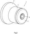
- Fig. 2 now shows a preferably used for the inventive device nozzle element 4, which consists first and essentially of a hollow cylindrical outer part 5 with a conical distribution 6 and arranged in the outer part 5 inner part 7, wherein the inner part 7, the open side of the hollow cylindrical outer part 5 almost completely closes.
- a recess 8 On the front side of the inner part 7, a recess 8 can be seen, which serves to receive the head of a screw 9 for connecting the outer part 5 and inner part 7.
- the nozzle member 4 shown in axial section, here it is seen that the inner part 7 has a central bore 10 which terminates in the recess 8 and has a hexagon socket 11 in its end region.
- the screw 9 is screwed through the recess 8 and the bore 10 with a retaining element 12, wherein the screw head comes to lie in the recess 8.
- the holding element 12 is conclusively connected to the outer element 5 and has an (unspecified) internal thread, in which the external thread of the inner end of the inner part 7 is screwed and thus adjustable in the axial direction.
- Fig. 3a In the broken view according to Fig. 3a It can be seen that the bore 10 in its end region adjacent to the recess 8 has a hexagon socket 11. This hexagon socket 11 is used for relative adjustment of outer part 5 and inner part 7 in the axial direction, as will be explained in more detail below.
- the end of the screw 9 engages in an internal thread of a counter element 13, whereby a precisely spaced fixation of the outer part 5 and inner part 7 takes place, as seen from Fig. 3 is clearly visible.
- the holding element 12 has a sufficient number of passage channels 14 for the hot gas. These lead into an annular space 15 between the inner part 7 and the outer part 5.
- the supply of hot gas necessary for activation preferably takes place in the in Fig. 3 illustrated embodiment, in which a narrow annular gap 16 remains as an outlet between the outer edge of the end face of the inner part 7 and the hollow cylindrical outer part 5, so that a uniform outlet of the hot gas is performed circumferentially over the entire circumference of the nozzle member 4.
- a circumferential recess 17 is executed, as from the Figures 2 . 3 and 3a is clearly visible. This allows a fluidically particularly uniform application of hot gas.
- Fig. 4 finally shows the previously described nozzle element 4 during an activation process.
- the nozzle member 4 is thereby introduced into the open end of a with the other end on a (not shown) mandrel of a mandrel wheel deferred packing jacket.
- the outer diameter of the cylindrical outer part 5 of the nozzle element 4 corresponds approximately to the inner diameter of the formed, tubular packaging casing 1, which is shown cut open for better representation.
Landscapes
- Engineering & Computer Science (AREA)
- Mechanical Engineering (AREA)
- Chemical & Material Sciences (AREA)
- Physics & Mathematics (AREA)
- Combustion & Propulsion (AREA)
- Composite Materials (AREA)
- Fluid Mechanics (AREA)
- Thermal Sciences (AREA)
- Making Paper Articles (AREA)
- Package Closures (AREA)
- Containers And Plastic Fillers For Packaging (AREA)
Description
- Die Erfindung betrifft ein Verfahren zum thermischen Aktivieren von rohrförmigen Verpackungsmänteln aus Karton/Kunststoff-Verbundmaterial, insbesondere für Verpackungen für flüssige Lebensmittel, wobei der rohrförmige Verpackungsmantel zur Herstellung des Bodens oder des Kopfes der Verpackung von einer Heizvorrichtung mit einem heißen Gas beaufschlagt wird, wobei die Heizvorrichtung in Wirkkontakt mit den zu aktivierenden Flächen gebracht wird, indem die Heizvorrichtung zum Aktivieren ins Innere des rohrförmigen Verpackungsmantels bewegt wird und wobei der rohrförmige Verpackungsmantel auf einem Dorn eines Dornrades angeordnet ist. Außerdem betrifft die Erfindung eine Vorrichtung zum thermischen Aktivieren von rohrförmigen Verpackungsmänteln aus Karton/Kunststoff-Verbundmaterial, insbesondere für Verpackungen für flüssige Lebensmittel, wobei der rohrförmige Verpackungsmantel zur Herstellung des Bodens oder des Kopfes der Verpackung von einer Heizvorrichtung mit einem heißen Gas beaufschlagt wird und wobei die Heizvorrichtung ein wenigstens eine Auslassöffnung aufweisendes Düsenelement aufweist, dessen äußere Form der inneren Form des zu aktivierenden Endes des rohrförmigen Verpackungsmantels entspricht.
- Die Herstellung von quaderförmigen Verpackungen aus Karton/Kunststoff-Verbundmaterial, insbesondere für flüssige Lebensmittel, ist seit langem bekannt. Diese Verpackungen haben oft einen rechteckigen oder quadratischen Querschnitt über die gesamte Höhe, es sind jedoch in jüngerer Zeit auch Verpackungen am Markt erhältlich, welche nicht über ihre gesamte Höhe einen konstanten Querschnitt aufweisen. Als Packstoff für solche Verpackungen dienen vollflächig miteinander verbundene Materialien (Laminat) mit einer Kartonschicht als Trägermaterial und auflaminierten Kunststoffschichten zum Schutz vor dem Eindringen von Feuchtigkeit in das Trägermaterial. Je nach Art der Verpackung und des zu verpackenden Produktes kann das Laminat auch weitere Schichten aufweisen, beispielsweise eine dünne Aluminiumfolie als Sauerstoff- und Lichtsperrschicht oder weitere Kunststoffschichten wie EVOH, sowie entsprechend notwendige Haftvermittlerschichten.
- In den meisten Fällen, insbesondere im Getränkebereich, weisen die bekannten Verbundverpackungen kombinierte Öffnungs- und Ausgießelemente auf, welche flüssigkeitsdicht mit der jeweiligen Verbundverpackung verbunden sind. Aus der
EP 0 907 576 B1 ist eine solche Verbundverpackung bekannt, die auf ihrer Kopfseite ein Ausgießelement aus Kunststoff beinhaltet, welches in einer Füllmaschine in die Verbundverpackung eingearbeitet wird. Dazu wird zunächst aus einem Zuschnitt ein rohrförmiger Verpackungsmantel durch eine Längsnahtsiegelung der PE-Schichten vorgefertigt. Die weitere Verarbeitung erfolgt dann auf einem Dornrad, wobei der rohrförmige Verpackungsmantel auf einen Dorn mit quadratischem Querschnitt aufgeschoben wird, um zunächst das überstehende freie Ende der späteren Verbundverpackung zu formen und zu verschließen. Wenn, wie dargestellt, die Verbundverpackung mit einem Ausgießelement versehen werden soll, so erfolgt zunächst die Fertigstellung der Kopfseite der Verbundpackung, wobei das Ausgießelement über den Dorn zugeführt und der rohrförmige Verpackungsmantel auf diesen aufgeschoben wird. Die Kopffaltung erfolgt dabei über zuvor eingebrachte Rilllinien, wobei die umzulegenden Giebelflächen mittels Presswerkzeugen auf die Stirnfläche des Dornes umgelegt werden. Für eine dauerhafte und flüssigkeitsdichte Verbindung werden die entsprechenden Kontaktflächen des Verbundmateriales mittels eines heißen Gases, beispielsweise mittels steriler Heißluft, erhitzt, so dass die äußeren PE-Flächen lokal aufschmelzen und so aktiviert werden. Anschließend werden die aktivierten PE-Flächen durch die Presswerkzeuge so lange druckbeaufschlagt, bis die fertige Giebelfläche flüssigkeitsdicht erkaltet ist. - Aus der
DE 10 2010 050 502 A1 sind eine Vorrichtung und ein Verfahren zur Herstellung einer Verpackung bekannt, bei welcher im Giebelbereich ein Ausgießelement eingearbeitet ist, welches nicht in einer flachen Giebelfläche angeordnet ist, sondern in einem Giebel in Form eines Pyramidenstumpfes. Eine damit hergestellte Verpackung hat im Giebelbereich neben den vier Giebelflächen auch vier vom Giebelbereich abstehende, aus überschüssigem Verpackungsmaterial gebildete Ohren, welche auf die Giebelflächen umgelegt und dort angeheftet werden. Die grundsätzliche Herstellung erfolgt dabei in der gleichen Weise, nämlich durch Aktivierung der zu versiegelnden Kontaktflächen mittels steriler Heißluft, wobei der rohrförmige Verpackungsmantel ebenfalls auf den Dorn eines Dornrades aufgeschoben ist. - Der Aktivierungsvorgang bei den bekannten Herstellungsverfahren geschieht dabei mittels Heizvorrichtungen unter Zufuhr des zur Aktivierung verwendeten Heißgases. Dabei müssen die Dauer und Temperatur der Aktivierung optimal auf das Verbundmaterial abgestimmt sein, um die gewünschte flüssigkeitsdichte Verbindung des Giebelbereichs zu erhalten. Gleiches gilt auch für solche Verpackungen, bei denen zunächst die Faltung und Versiegelung des Bodenbereiches erfolgt, welche nicht von unten, sondern in "klassischer Weise" von oben befüllt werden. Die bekannten Heizvorrichtungen haben teilweise einen komplizierten Aufbau und sind daher teuer in ihrer Herstellung und wartungsintensiv.
- Der Erfindung liegt daher die Aufgabe zu Grunde, das eingangs genannte Verfahren bzw. eine entsprechende Vorrichtung zum thermischen Aktivieren von rohrförmigen Verpackungsmänteln so auszugestalten und weiterzubilden, dass die verwendete Heizvorrichtung konstruktiv einfach hergestellt werden kann und eine gleichmäßige Erwärmung zum Aktivieren der Kontaktflächen gewährleistet wird. Weiterhin ist erwünscht, dass die für den Aktivierungsprozess benötigte Energie möglichst vollständig zur Erhitzung der zu aktivierenden Oberflächen genutzt wird.
- Verfahrensmäßig wird die Aufgabe dadurch gelöst, dass vor dem Einführen der Heizvorrichtung das freie Ende des rohrförmigen Verpackungsmantels zeitweise von einem rechteckigen oder quadratischen Querschnitt zu einem runden Querschnitt verformt wird. Durch einen solchen innigen Kontakt wird die für den Aktivierungsvorgang notwendige Energie unmittelbar und gleichmäßig in die zu erwärmenden Flächen eingebracht. Während der Dorn einen rechteckigen oder quadratischen Querschnitt entsprechend der späteren Verpackungsform aufweist, hat die Erfindung erkannt, dass eine zeitweise Umformung des freien Endes in eine runde Querschnittsform für den Aktivierungsvorgang äußerst vorteilhaft ist. Auf diese Weise erfolgt eine besonders gleichmäßige Erwärmung, da keine Kanten- und Eckbereiche vorhanden sind, in denen sich das Heißgas stauen kann. Dies führt zu einem verbesserten Siegelprozess und zu einer optimalen Energieausbeute, ohne dass es zur Gefahr von Überhitzungen kommen kann.
- Hinsichtlich einer entsprechenden Vorrichtung erfolgt die Lösung der Aufgabe dadurch, dass das Düsenelement an seinem freien Ende eine zylindrische Form aufweist und dass Einrichtungen zum zeitweisen Verformen des freien Endes des rohrförmigen Verpackungsmantels von einem rechteckigen oder quadratischen Querschnitt zu einem runden Querschnitt vorgesehen sind. Erfindungsgemäß gelangt so die gesamte Heißluft unmittelbar an die zu aktivierenden Kunststoffoberflächen des Verbundmaterials und beinhaltet eine optimale Ausnutzung der eingesetzten Energie. Dies ist konstruktiv besonders zweckmäßig, wenn die äußere Form des zylindrischen Düsenelements in ihrem Durchmesser nahezu dem Innendurchmesser des im Aktivierungsbereich nun einen runden Querschnitt aufweisenden, rohrförmigen Verpackungsmantel entspricht. Durch die konstruktive Abstimmung von Düsenelement und Verpackungsmantel kann die verwendete Energie unmittelbar zur Aktivierung der Kunststoffoberflächen eingesetzt werden, ohne dass Verluste entstehen.
- Eine weitere Lehre der Erfindung sieht vor, dass die Heizvorrichtung während des Aktivierungsvorganges relativ zum rohrförmigen Verpackungsmantel bewegt wird. Hierbei kann die zu aktivierende Fläche durch ein Abfahren der Austrittsöffnungen des Heißgases vergrößert werden. Es ist jedoch auch möglich, den Aktivierungsvorgang ohne Relativbewegung durchzuführen.
- Eine weitere Ausgestaltung der Erfindung sieht vor, dass die Auslassöffnungen des Düsenelements schlitzförmig oder gelocht ausgebildet sind. Besonders vorteilhaft ist es, wenn gemäß einer weiteren Ausbildung der Erfindung die Auslassöffnung des Düsenelements als umlaufender Ringspalt ausgebildet ist. Dies erlaubt einerseits eine besonders günstige Herstellung des Düsenelements und andererseits eine extrem gleichmäßige Erhitzung der zu aktivierenden Oberflächen.
- Nach einer weiteren Lehre der Erfindung weist das Düsenelement ein zylindrischen Außenteil und ein mit diesem verbindbaren Innenteil sowie einem Ringraum zwischen Außenteil und Innenteil als Ringkanal zum Zuführen des Heißgases auf. Ein zylindrisches Düsenelement ist konstruktiv extrem einfach als Rotationsteil herzustellen, zweckmäßigerweise mit einem Außenbereichsdurchmesser, welcher im Wesentlichen dem Innendurchmesser des vorrübergehend umgeformten rohrförmigen Verpackungsmantels an dessen freien Ende entspricht.
- Eine weitere bevorzugte Ausgestaltung der Erfindung sieht vor, dass die Auslassöffnungen in einer umlaufenden Ausnehmung münden. Auf diese Weise kann auf zusätzliche Kanäle, Bohrungen oder dergleichen zum Zuführen des Heißgases in die umlaufende Ausnehmung komplett verzichtet werden. Dies hat nicht nur eine besonders einfache Art der Herstellung sondern wiederum eine besonders gleichmäßige Erhitzung und damit einen verbesserten Siegelprozess zur Folge.
- Eine weitere Lehre der Erfindung sieht vor, dass zur Verstellung der Größe des Spaltes das Außenteil und das Innenteil in axialer Richtung relativ zueinander verfahrbar sind. Auf diese Weise lässt sich eine optimale Einstellung des benötigten Heißgases für den jeweiligen Aktivierungsprozess definieren und festlegen und, im Bedarfsfall, auch mit wenig Aufwand an die geänderten Verhältnisse, beispielsweise eines anderen Verpackungsmantels, anpassen.
- In weiterer Ausgestaltung der Erfindung ist vorgesehen, dass das Innenteil in einem Gewinde eines fest mit dem Außenteil verbundenen Halteelements verstellbar ist.
- Eine solche Konstruktion ist besonders zweckmäßig, da hierdurch eine sehr genaue Verstellung möglich ist. Bevorzugt erfolgt die Verstellung von außen her über einen Sechskantschlüssel, wobei das Innenteil einen entsprechenden zentral angeordneten Innensechskant aufweist.
- Eine andere Ausgestaltung der Erfindung sieht vor, dass das Innenteil mit einer Schraube und/oder einem Konterelement im Halteelement gesichert ist. Hierbei wird das Innenteil verstellsicher fixiert.
- Eine weitere Lehre der Erfindung sieht vor, dass die bereits erwähnten Einrichtungen zum Verformen des freien Endes des rohrförmigen Verpackungsmantels mehrere Werkzeuge aufweisen, welche in radialer Richtung von außen auf den Verpackungsmantel einwirken und in ihrer Eingriffsstellung gemeinsam eine runde Innenform ergeben. Dabei ist es besonders zweckmäßig, wenn als Werkzeuge halbhohlzylindrische Formbacken vorgesehen sind, welche diametral gegenüberliegend angeordnet sind und durch Aufeinanderzubewegen das freie Ende des rohrförmigen Verpackungsmantels vorübergehend von ihrem rechteckigen oder quadratischen Querschnitt in die gewünschte runde Form bringen.
- Eine alternative Ausbildung der Einrichtungen zum Verformen des freien Endes des rohrförmigen Verpackungsmantels sieht vor, dass eine axial auf den Verpackungsmantels aufschiebbare Matrize vorgesehen ist, welche in axialer Richtung außen um den Dorn herum zum Dornrad hin verfahrbar ist, wobei das freie Ende der Matrize von der Querschnittsform des Dornes in einen Bereich mit kreisrundem Querschnitt übergeht. Die Herstellung einer solchen Matrize ist jedoch im Vergleich zu den bevorzugten Zangenelementen deutlich aufwendiger.
- Die Erfindung wird nachfolgend anhand einer lediglich ein bevorzugtes Ausführungsbeispiel darstellenden Zeichnung näher erläutert.
- In der Zeichnung zeigen
- Fig. 1
- einen rohrförmigen Verpackungsmantel in perspektivischer Ansicht,
- Fig. 2
- ein Düsenelement einer erfindungsgemäßen Vorrichtung in perspektivischer Ansicht,
- Fig. 3
- das Düsenelement aus
Fig. 2 im Axialschnitt, - Fig. 3a
- Außenteil und Innenteil des Düsenelements in teilweise aufgebrochener Darstellung und
- Fig. 4
- das Düsenelement in Aktivierungsstellung in perspektivischer Ansicht mit zur besseren Darstellung aufgeschnittenem Verpackungsmantel.
-
Fig. 1 zeigt zunächst einen rohrförmigen Verpackungsmantel 1 als Packmittel für eine spätere Getränkeverpackung. Ein solcher Verpackungsmantel 1 ist durch Längssiegelung aus einem Zuschnitt hergestellt, wobei die Längsnaht nicht dargestellt ist. Diese kann sich an einer beliebigen Stelle, beispielsweise im Mittelbereich oder an einer der Kanten 2 befinden. Ferner sind Rilllinien 3 zu erkennen, welche zur Faltung von Boden und Giebelbereich (Kopfbereich) der späteren Verpackung dienen. -
Fig. 2 zeigt nun ein für die erfindungsgemäße Vorrichtung bevorzugt verwendetes Düsenelement 4, welches zunächst und im Wesentlichen aus einem hohlzylindrischen Außenteil 5 mit einer konischen Verbreitung 6 und einem im Außenteil 5 angeordneten Innenteil 7 besteht, wobei das Innenteil 7 die offene Seite des hohlzylinderförmigen Außenteils 5 nahezu vollständig verschließt. Auf der Stirnseite des Innenteils 7 ist eine Ausnehmung 8 erkennbar, welche zur Aufnahme des Kopfes einer Schraube 9 zur Verbindung von Außenteil 5 und Innenteil 7 dient. - Zur besseren Darstellung ist in
Fig. 3 das Düsenelement 4 im Axialschnitt dargestellt, hier wird ersichtlich, dass das Innenteil 7 eine zentrale Bohrung 10 aufweist, welche in der Ausnehmung 8 endet und in ihrem Endbereich einen Innensechskant 11 aufweist. Die Befestigung von Außenteil 5 und Innenteil 7 erfolgt mittels der bereits erwähnten Verschraubung durch diese Bohrung 10. Dabei wird die Schraube 9 durch die Ausnehmung 8 und die Bohrung 10 mit einem Halteelement 12 verschraubt, wobei der Schraubenkopf in der Ausnehmung 8 zu liegen kommt. Das Halteelement 12 ist schlüssig mit dem Außenelement 5 verbunden und verfügt über ein (nicht näher bezeichnetes) Innengewinde, in dem das Außengewinde des inneren Endes des Innenteils 7 verschraubt und so in axialer Richtung verstellbar ist. - In der aufgebrochenen Darstellung gemäß
Fig. 3a ist erkennbar, dass die Bohrung 10 in ihrem Endbereich benachbart zur Ausnehmung 8 einen Innensechskant 11 aufweist. Dieser Innensechskant 11 dient zur relativen Verstellung von Außenteil 5 und Innenteil 7 in axialer Richtung, wie weiter unten noch näher erläutert werden wird. Das Ende der Schraube 9 greift in ein Innengewinde eines Konterelementes 13 ein, wodurch eine genau beabstandete Fixierung von Außenteil 5 und Innenteil 7 erfolgt, wie ausFig. 3 deutlich ersichtlich ist. - Das Halteelement 12 weist eine ausreichende Anzahl an Durchtrittskanälen 14 für das Heißgas auf. Diese führen in einen Ringraum 15 zwischen Innenteil 7 und Außenteil 5. Die Zufuhr des zur Aktivierung notwendigen Heißgases, beispielsweise steriler Heißluft, erfolgt dabei bevorzugt in der in
Fig. 3 dargestellten Ausführung, in der nämlich ein schmaler Ringspalt 16 als Auslassöffnung zwischen dem äußeren Rand der Stirnfläche des Innenteils 7 und dem hohlzylinderförmigen Außenteil 5 verbleibt, so dass ein gleichmäßiger Austritt des Heißgases umlaufend über den gesamten Umfang des Düsenelements 4 erfolgt. Gleich hinter der Düsenauslassöffnung ist im dargestellten und insoweit bevorzugten Ausführungsbeispiel eine umlaufende Ausnehmung 17 ausgeführt, wie aus denFiguren 2 ,3 und 3a deutlich ersichtlich ist. Dadurch wird eine strömungstechnisch besonders gleichmäßige Beaufschlagung mit Heißgas ermöglicht. -
Fig. 4 zeigt schließlich das zuvor näher beschriebene Düsenelement 4 während eines Aktivierungsvorganges. Das Düsenelement 4 wird dabei in das offene Ende eines mit dem anderen Ende auf einem (nicht dargestellten) Dorn eines Dornrades aufgeschobenen Packungsmantels eingeführt. Man erkennt, dass der äußere Durchmesser des zylindrischen Außenteils 5 des Düsenelements 4 in etwa dem Innendurchmesser des zurechtgeformten, rohrförmigen Verpackungsmantels 1 entspricht, welcher zur besseren Darstellung mittig aufgeschnitten dargestellt ist. - Damit nun das freie Ende des rohrförmigen Verpackungsmantels 1 in die gewünschte runde Form gebracht wird, sorgen erfindungsgemäß zwei halbhohlzylindrische Formbacken 18 für die entsprechende Formgebung. Auch hier ist aus Gründen der übersichtlichen Darstellung nur eine der beiden Formbacken 18 dargestellt. Zur Verformung werden dabei die beiden Formbacken 18 aufeinander zu bewegt, wobei sich das freie Ende des rohrförmigen Verpackungsmantels 1 "automatisch" auf einfache und elegante Weise in die gewünschte runde Form bringen lässt.
- Mit der erfindungsgemäßen Lösung ist eine optimale Energieausnutzung beim Aktivierungsvorgang erreicht worden, wobei zuverlässig durch die gleichmäßige Beaufschlagung des Heißgases über den gesamten Umfang des Düsenelementes eine optimal gleichmäßige Aktivierung erreicht wird.
Claims (14)
- Verfahren zum thermischen Aktivieren von rohrförmigen Verpackungsmänteln aus Karton/Kunststoff-Verbundmaterial, insbesondere für Verpackungen für flüssige Lebensmittel, wobei der rohrförmige Verpackungsmantel zur Herstellung des Bodens oder des Kopfes der Verpackung von einer Heizvorrichtung mit einem heißen Gas beaufschlagt wird, wobei die Heizvorrichtung in Wirkkontakt mit den zu aktivierenden Flächen gebracht wird, indem die Heizvorrichtung zum Aktivieren ins Innere des rohrförmigen Verpackungsmantels bewegt wird, und wobei der rohrförmige Verpackungsmantel auf einem Dorn eines Dornrades angeordnet ist,
dadurch gekennzeichnet, dass
vor dem Einführen der Heizvorrichtung das freie Ende des rohrförmigen Verpackungsmantels zeitweise von einem rechteckigen oder quadratischen Querschnitt zu einem runden Querschnitt verformt wird. - Verfahren nach Anspruch 1,
dadurch gekennzeichnet, dass
die Heizvorrichtung während des Aktivierungsvorgangs relativ zum rohrförmigen Verpackungsmantel bewegt wird. - Vorrichtung zum thermischen Aktivieren von rohrförmigen Verpackungsmänteln (1) aus Karton/Kunststoff-Verbundmaterial, insbesondere für Verpackungen für flüssige Lebensmittel, wobei der rohrförmige Verpackungsmantel (1) zur Herstellung des Bodens oder des Kopfes der Verpackung von einer Heizvorrichtung mit einem heißen Gas beaufschlagt wird und wobei die Heizvorrichtung ein wenigstens eine Auslassöffnung aufweisendes Düsenelement (4) aufweist, dessen äußere Form der inneren Form des zu aktivierenden Endes des rohrförmigen Verpackungsmantels (1) entspricht,
dadurch gekennzeichnet, dass
das Düsenelement (4) an seinem freien Ende eine zylindrische Form aufweist und dass Einrichtungen zum zeitweisen Verformen des freien Endes des rohrförmigen Verpackungsmantels (1) von einem rechteckigen oder quadratischen Querschnitt zu einem runden Querschnitt vorgesehen sind. - Vorrichtung nach Anspruch 3,
dadurch gekennzeichnet, dass
die Auslassöffnungen des Düsenelements (4) schlitzförmig oder gelocht ausgebildet sind. - Vorrichtung nach Anspruch 3,
dadurch gekennzeichnet, dass
die Auslassöffnung des Düsenelements (4) als umlaufender Ringspalt (16) ausgebildet ist. - Vorrichtung nach einem der Ansprüche 3 bis 5,
dadurch gekennzeichnet, dass
das Düsenelement (4) ein zylindrisches Außenteil (5) und ein mit diesem verbindbares Innenteil (7) aufweist und dass der Ringraum zwischen Außenteil (5) und Innenteil (7) als Ringkanal (15) zum Zuführen des Heißgases ausgebildet ist. - Vorrichtung nach einem der Ansprüche 3 bis 6,
dadurch gekennzeichnet, dass
die Auslassöffnungen in einer umlaufenden Ausnehmung (17) münden. - Vorrichtung nach Anspruch 5,
dadurch gekennzeichnet, dass
zur Verstellung der Größe des Ringspaltes (16) das Außenteil (5) und das Innenteil (7) in axialer Richtung relativ zueinander verfahrbar sind. - Vorrichtung nach Anspruch 8,
dadurch gekennzeichnet, dass
das Innenteil (7) in einem Gewinde eines fest mit dem Außenteil (5) verbundenen Halteelements (12) verstellbar ist. - Vorrichtung nach Anspruch 9,
dadurch gekennzeichnet, dass
das Innenteil (7) mit einer Schraube (9) und/oder einem Konterelement (13) im Halteelement (12) gesichert ist. - Vorrichtung nach Anspruch 9 oder 10,
dadurch gekennzeichnet, dass
das Innenteil (7) mit einem zentral angeordneten Innensechskant (11) versehen ist. - Vorrichtung nach einem der Ansprüche 3 bis 11,
dadurch gekennzeichnet, dass
die Einrichtungen zum Verformen des freien Endes des rohrförmigen Verpackungsmantels (1) mehrere Werkzeuge aufweisen, welche in radialer Richtung von außen auf den Verpackungsmantel (1) einwirken und in ihrer Eingriffsstellung gemeinsam eine runde Innenform ergeben. - Vorrichtung nach Anspruch 12,
dadurch gekennzeichnet, dass
als Werkzeuge halbhohlzylindrische Formbacken (18) vorgesehen sind. - Vorrichtung nach einem der Ansprüche 3 bis 11,
dadurch gekennzeichnet, dass
die Einrichtungen zum Verformen des freien Endes des rohrförmigen Verpackungsmantels eine axial auf den Verpackungsmantel aufschiebbare Matrize aufweisen.
Applications Claiming Priority (2)
| Application Number | Priority Date | Filing Date | Title |
|---|---|---|---|
| DE102014006099.3A DE102014006099B4 (de) | 2014-04-29 | 2014-04-29 | Verfahren und Vorrichtung zum thermischen Aktivieren von Verpackungsmänteln |
| PCT/EP2015/059307 WO2015165945A1 (de) | 2014-04-29 | 2015-04-29 | Verfahren und vorrichtung zum thermischen aktivieren von verpackungsmänteln |
Publications (2)
| Publication Number | Publication Date |
|---|---|
| EP3137382A1 EP3137382A1 (de) | 2017-03-08 |
| EP3137382B1 true EP3137382B1 (de) | 2018-03-07 |
Family
ID=53177450
Family Applications (1)
| Application Number | Title | Priority Date | Filing Date |
|---|---|---|---|
| EP15722467.6A Not-in-force EP3137382B1 (de) | 2014-04-29 | 2015-04-29 | Verfahren und vorrichtung zum thermischen aktivieren von verpackungsmänteln |
Country Status (9)
| Country | Link |
|---|---|
| US (1) | US10843832B2 (de) |
| EP (1) | EP3137382B1 (de) |
| JP (1) | JP2017514726A (de) |
| CN (1) | CN106255642B (de) |
| AU (1) | AU2015254719A1 (de) |
| BR (1) | BR112016024333A2 (de) |
| DE (1) | DE102014006099B4 (de) |
| MX (1) | MX2016011986A (de) |
| WO (1) | WO2015165945A1 (de) |
Families Citing this family (6)
| Publication number | Priority date | Publication date | Assignee | Title |
|---|---|---|---|---|
| US10040264B2 (en) * | 2015-04-01 | 2018-08-07 | Dart Container Corporation | Container bottom heater |
| CN109049858A (zh) * | 2018-07-20 | 2018-12-21 | 浙江森盟包装有限公司 | 吹热风装置 |
| IT201900014418A1 (it) * | 2019-08-08 | 2021-02-08 | Azionaria Costruzioni Acma Spa | Macchina e metodo per la formatura di contenitori a partire da sbozzati |
| CN113858697A (zh) * | 2020-06-30 | 2021-12-31 | 康美包(苏州)有限公司 | 一种可微波包装盒端部密封方法、装置及可微波包装盒 |
| CN113510968B (zh) * | 2021-04-01 | 2022-12-16 | 浙江新德宝机械有限公司 | 纸容器筒身成型模具装置以及纸容器成型设备 |
| DE102021114623A1 (de) * | 2021-06-08 | 2022-12-08 | Sig Technology Ag | Verfahren und Vorrichtung zum Erwärmen der Bodenbereiche von Packungsmänteln aus Verbundmaterial |
Family Cites Families (18)
| Publication number | Priority date | Publication date | Assignee | Title |
|---|---|---|---|---|
| US2169345A (en) | 1937-05-24 | 1939-08-15 | Jagenberg Werke Ag | Method and machine for producing paper containers |
| US2467930A (en) * | 1944-01-14 | 1949-04-19 | Continental Can Co | Paper container structure and method of forming same |
| US3825408A (en) * | 1973-09-07 | 1974-07-23 | Phillips Petroleum Co | Hot air heater for carton sealing machine |
| SE8300277L (sv) | 1983-01-20 | 1984-07-21 | Norden Packaging Mach | Forseglingsanordning |
| US4838009A (en) | 1988-08-31 | 1989-06-13 | International Paper Company | Method of heat activating top closure panels |
| US5577907A (en) * | 1991-09-04 | 1996-11-26 | Norden Pac Development Ab | Hot gas heating device |
| SE9102528D0 (sv) | 1991-09-04 | 1991-09-04 | Norden Pac Dev Ab | Hot gas heating device |
| US5507640A (en) * | 1992-12-11 | 1996-04-16 | Amoco Corporation | Apparatus and method useful in manufacture of two piece cups |
| JPH09142417A (ja) * | 1995-11-22 | 1997-06-03 | Dainippon Printing Co Ltd | 液体紙容器シール用熱風加熱装置 |
| US5704541A (en) | 1996-04-25 | 1998-01-06 | Tetra Laval Holdings & Finance S.A. | Flat-top container with an opening fitment |
| WO1999029572A1 (en) * | 1997-12-05 | 1999-06-17 | Norden Pac Development Ab | Method and device for end closure of packaging tubes |
| JP2003011249A (ja) | 2001-07-03 | 2003-01-15 | Dainippon Printing Co Ltd | 紙カップ成形機 |
| PT1497108E (pt) | 2002-04-24 | 2006-11-30 | Werner Grabher | Lata provida de linhas de dobra e processo para fabrico da mesma |
| DE10336788A1 (de) * | 2003-08-08 | 2005-03-17 | Sig Technology Ltd. | Vorrichtung und Verfahren zum Befestigen von Verschlussfolien an auf Verbundpackungen angeordneten Ausgiesselementen |
| WO2005120964A1 (en) | 2004-06-10 | 2005-12-22 | Elopak Systems Ag | Container made of laminate material, blank and method |
| US7516599B2 (en) * | 2005-11-07 | 2009-04-14 | Kraft Foods Global Brands Llc | Methods and apparatus for manufacture of a reclosable plastic carton |
| DE102006042506B4 (de) * | 2006-09-07 | 2015-04-16 | Sig Technology Ag | Verfahren und Vorrichtung zur Herstellung einer Karton/Kunststoff-Verbundverpackung |
| DE102010050502A1 (de) * | 2010-11-08 | 2012-05-10 | Sig Technology Ag | Vorrichtung und Verfahren zur Herstellung einer Verpackung |
-
2014
- 2014-04-29 DE DE102014006099.3A patent/DE102014006099B4/de not_active Expired - Fee Related
-
2015
- 2015-04-29 EP EP15722467.6A patent/EP3137382B1/de not_active Not-in-force
- 2015-04-29 CN CN201580023081.XA patent/CN106255642B/zh not_active Expired - Fee Related
- 2015-04-29 MX MX2016011986A patent/MX2016011986A/es unknown
- 2015-04-29 US US15/307,515 patent/US10843832B2/en not_active Expired - Fee Related
- 2015-04-29 WO PCT/EP2015/059307 patent/WO2015165945A1/de not_active Ceased
- 2015-04-29 JP JP2016565217A patent/JP2017514726A/ja not_active Ceased
- 2015-04-29 AU AU2015254719A patent/AU2015254719A1/en not_active Abandoned
- 2015-04-29 BR BR112016024333A patent/BR112016024333A2/pt not_active Application Discontinuation
Also Published As
| Publication number | Publication date |
|---|---|
| DE102014006099B4 (de) | 2017-11-30 |
| US10843832B2 (en) | 2020-11-24 |
| JP2017514726A (ja) | 2017-06-08 |
| CN106255642B (zh) | 2019-05-21 |
| CN106255642A (zh) | 2016-12-21 |
| DE102014006099A1 (de) | 2015-10-29 |
| MX2016011986A (es) | 2016-12-09 |
| EP3137382A1 (de) | 2017-03-08 |
| AU2015254719A2 (en) | 2017-02-02 |
| WO2015165945A1 (de) | 2015-11-05 |
| AU2015254719A1 (en) | 2016-09-29 |
| US20170050403A1 (en) | 2017-02-23 |
| BR112016024333A2 (pt) | 2017-08-15 |
Similar Documents
| Publication | Publication Date | Title |
|---|---|---|
| EP3137382B1 (de) | Verfahren und vorrichtung zum thermischen aktivieren von verpackungsmänteln | |
| EP2637854B1 (de) | Vorrichtung und verfahren zur herstellung einer verpackung sowie giebelpresse | |
| EP2986514B1 (de) | Portionenkapsel zum zubereiten eines brüherzeugnisses | |
| EP3140200B1 (de) | Verfahren und vorrichtung zur herstellung von formteilen aus einer faserwerkstoffbahn | |
| CH638716A5 (de) | Verfahren zur herstellung eines formkoerpers aus kunststoff. | |
| DE2759138C3 (de) | Verfahren und Vorrichtung zur Herstellung von insbesondere zylinderformigen Behältern | |
| DE69202339T2 (de) | Verfahren und vorrichtung zur herstellung von verpackungen aus dünnen folienmaterial. | |
| DE202014011245U1 (de) | Verpackung für ein Lebensmittelprodukt, insbesondere ein Süßwarenprodukt | |
| DE69311375T2 (de) | Aus mehreren tuben bestehender verpackungsbehälter und verfahren zu dessen herstellung | |
| DE102015101417A1 (de) | Verfahren zum Herstellen einer Verpackung | |
| DE2541912C2 (de) | Behälter, insbesondere Verpackungsbehälter, sowie Verfahren zum Herstellen eines solchen Behälters und Vorrichtung zum Durchführen des Verfahrens | |
| DE102013226952B4 (de) | In-Mould-Labeling-Verfahren und In-Mould-Labeling-Vorrichtung | |
| DE19741859A1 (de) | Dose und Vorrichtung zum Herstellen der Dose | |
| CH635792A5 (en) | Squeezable delivery container | |
| DE102017204553A1 (de) | Ventilvorrichtung, ventilgehäuse, zahnsegmenteinrichtung und verfahren zum herstellen der ventilvorrichtung | |
| EP2955011B1 (de) | Verfahren und vorrichtung zum herstellen eines bechers | |
| EP3907145A1 (de) | Verfahren zur herstellung einer portionenkapsel, und portionenkapsel | |
| DE60004557T2 (de) | Verfahren und vorrichtung zum verschliessen einer verpackungshülse | |
| EP3724082B1 (de) | Verpackung und verfahren zu deren herstellung | |
| EP2268552A1 (de) | Becher und herstellungsverfahren hierfür | |
| DE69903516T2 (de) | Verfahren zum herstellen eines metallbehalters mit einem einsatzstück zum verpacken ,zum beispiel, ein nahrungsmittel, und so ein behalter | |
| EP1568451B1 (de) | Verfahren und Vorrichtung zum Stanzen eines Filtermaterials | |
| EP3271165B1 (de) | Dornrad zur herstellung von verpackungen | |
| EP4045384B1 (de) | Vorrichtung und verfahren zum stoffschlüssigen verbinden von mindestens einem materialsegment mit einer lenkvorrichtung | |
| WO1992007662A1 (de) | Vorrichtung zum intermittierenden auftragen eines fluids auf ein substrat |
Legal Events
| Date | Code | Title | Description |
|---|---|---|---|
| PUAI | Public reference made under article 153(3) epc to a published international application that has entered the european phase |
Free format text: ORIGINAL CODE: 0009012 |
|
| 17P | Request for examination filed |
Effective date: 20161028 |
|
| AK | Designated contracting states |
Kind code of ref document: A1 Designated state(s): AL AT BE BG CH CY CZ DE DK EE ES FI FR GB GR HR HU IE IS IT LI LT LU LV MC MK MT NL NO PL PT RO RS SE SI SK SM TR |
|
| AX | Request for extension of the european patent |
Extension state: BA ME |
|
| DAV | Request for validation of the european patent (deleted) | ||
| DAX | Request for extension of the european patent (deleted) | ||
| GRAP | Despatch of communication of intention to grant a patent |
Free format text: ORIGINAL CODE: EPIDOSNIGR1 |
|
| INTG | Intention to grant announced |
Effective date: 20170919 |
|
| RIN1 | Information on inventor provided before grant (corrected) |
Inventor name: WEBER, DANIEL Inventor name: RUEEGG, MARTIN Inventor name: PLUESS, MARCO Inventor name: POELL, HOLGER |
|
| GRAS | Grant fee paid |
Free format text: ORIGINAL CODE: EPIDOSNIGR3 |
|
| GRAA | (expected) grant |
Free format text: ORIGINAL CODE: 0009210 |
|
| AK | Designated contracting states |
Kind code of ref document: B1 Designated state(s): AL AT BE BG CH CY CZ DE DK EE ES FI FR GB GR HR HU IE IS IT LI LT LU LV MC MK MT NL NO PL PT RO RS SE SI SK SM TR |
|
| REG | Reference to a national code |
Ref country code: GB Ref legal event code: FG4D Free format text: NOT ENGLISH |
|
| REG | Reference to a national code |
Ref country code: CH Ref legal event code: EP Ref country code: AT Ref legal event code: REF Ref document number: 976277 Country of ref document: AT Kind code of ref document: T Effective date: 20180315 |
|
| REG | Reference to a national code |
Ref country code: IE Ref legal event code: FG4D Free format text: LANGUAGE OF EP DOCUMENT: GERMAN |
|
| REG | Reference to a national code |
Ref country code: DE Ref legal event code: R096 Ref document number: 502015003299 Country of ref document: DE |
|
| REG | Reference to a national code |
Ref country code: FR Ref legal event code: PLFP Year of fee payment: 4 |
|
| REG | Reference to a national code |
Ref country code: NL Ref legal event code: MP Effective date: 20180307 |
|
| REG | Reference to a national code |
Ref country code: LT Ref legal event code: MG4D |
|
| PG25 | Lapsed in a contracting state [announced via postgrant information from national office to epo] |
Ref country code: LT Free format text: LAPSE BECAUSE OF FAILURE TO SUBMIT A TRANSLATION OF THE DESCRIPTION OR TO PAY THE FEE WITHIN THE PRESCRIBED TIME-LIMIT Effective date: 20180307 Ref country code: ES Free format text: LAPSE BECAUSE OF FAILURE TO SUBMIT A TRANSLATION OF THE DESCRIPTION OR TO PAY THE FEE WITHIN THE PRESCRIBED TIME-LIMIT Effective date: 20180307 Ref country code: HR Free format text: LAPSE BECAUSE OF FAILURE TO SUBMIT A TRANSLATION OF THE DESCRIPTION OR TO PAY THE FEE WITHIN THE PRESCRIBED TIME-LIMIT Effective date: 20180307 Ref country code: FI Free format text: LAPSE BECAUSE OF FAILURE TO SUBMIT A TRANSLATION OF THE DESCRIPTION OR TO PAY THE FEE WITHIN THE PRESCRIBED TIME-LIMIT Effective date: 20180307 Ref country code: NO Free format text: LAPSE BECAUSE OF FAILURE TO SUBMIT A TRANSLATION OF THE DESCRIPTION OR TO PAY THE FEE WITHIN THE PRESCRIBED TIME-LIMIT Effective date: 20180607 Ref country code: CY Free format text: LAPSE BECAUSE OF FAILURE TO SUBMIT A TRANSLATION OF THE DESCRIPTION OR TO PAY THE FEE WITHIN THE PRESCRIBED TIME-LIMIT Effective date: 20180307 |
|
| PG25 | Lapsed in a contracting state [announced via postgrant information from national office to epo] |
Ref country code: SE Free format text: LAPSE BECAUSE OF FAILURE TO SUBMIT A TRANSLATION OF THE DESCRIPTION OR TO PAY THE FEE WITHIN THE PRESCRIBED TIME-LIMIT Effective date: 20180307 Ref country code: LV Free format text: LAPSE BECAUSE OF FAILURE TO SUBMIT A TRANSLATION OF THE DESCRIPTION OR TO PAY THE FEE WITHIN THE PRESCRIBED TIME-LIMIT Effective date: 20180307 Ref country code: BG Free format text: LAPSE BECAUSE OF FAILURE TO SUBMIT A TRANSLATION OF THE DESCRIPTION OR TO PAY THE FEE WITHIN THE PRESCRIBED TIME-LIMIT Effective date: 20180607 Ref country code: GR Free format text: LAPSE BECAUSE OF FAILURE TO SUBMIT A TRANSLATION OF THE DESCRIPTION OR TO PAY THE FEE WITHIN THE PRESCRIBED TIME-LIMIT Effective date: 20180608 Ref country code: RS Free format text: LAPSE BECAUSE OF FAILURE TO SUBMIT A TRANSLATION OF THE DESCRIPTION OR TO PAY THE FEE WITHIN THE PRESCRIBED TIME-LIMIT Effective date: 20180307 |
|
| PG25 | Lapsed in a contracting state [announced via postgrant information from national office to epo] |
Ref country code: MT Free format text: LAPSE BECAUSE OF FAILURE TO SUBMIT A TRANSLATION OF THE DESCRIPTION OR TO PAY THE FEE WITHIN THE PRESCRIBED TIME-LIMIT Effective date: 20180307 |
|
| PG25 | Lapsed in a contracting state [announced via postgrant information from national office to epo] |
Ref country code: AL Free format text: LAPSE BECAUSE OF FAILURE TO SUBMIT A TRANSLATION OF THE DESCRIPTION OR TO PAY THE FEE WITHIN THE PRESCRIBED TIME-LIMIT Effective date: 20180307 Ref country code: PL Free format text: LAPSE BECAUSE OF FAILURE TO SUBMIT A TRANSLATION OF THE DESCRIPTION OR TO PAY THE FEE WITHIN THE PRESCRIBED TIME-LIMIT Effective date: 20180307 Ref country code: EE Free format text: LAPSE BECAUSE OF FAILURE TO SUBMIT A TRANSLATION OF THE DESCRIPTION OR TO PAY THE FEE WITHIN THE PRESCRIBED TIME-LIMIT Effective date: 20180307 Ref country code: NL Free format text: LAPSE BECAUSE OF FAILURE TO SUBMIT A TRANSLATION OF THE DESCRIPTION OR TO PAY THE FEE WITHIN THE PRESCRIBED TIME-LIMIT Effective date: 20180307 Ref country code: RO Free format text: LAPSE BECAUSE OF FAILURE TO SUBMIT A TRANSLATION OF THE DESCRIPTION OR TO PAY THE FEE WITHIN THE PRESCRIBED TIME-LIMIT Effective date: 20180307 |
|
| PG25 | Lapsed in a contracting state [announced via postgrant information from national office to epo] |
Ref country code: SM Free format text: LAPSE BECAUSE OF FAILURE TO SUBMIT A TRANSLATION OF THE DESCRIPTION OR TO PAY THE FEE WITHIN THE PRESCRIBED TIME-LIMIT Effective date: 20180307 Ref country code: CZ Free format text: LAPSE BECAUSE OF FAILURE TO SUBMIT A TRANSLATION OF THE DESCRIPTION OR TO PAY THE FEE WITHIN THE PRESCRIBED TIME-LIMIT Effective date: 20180307 Ref country code: SK Free format text: LAPSE BECAUSE OF FAILURE TO SUBMIT A TRANSLATION OF THE DESCRIPTION OR TO PAY THE FEE WITHIN THE PRESCRIBED TIME-LIMIT Effective date: 20180307 |
|
| REG | Reference to a national code |
Ref country code: CH Ref legal event code: PL |
|
| REG | Reference to a national code |
Ref country code: DE Ref legal event code: R097 Ref document number: 502015003299 Country of ref document: DE |
|
| REG | Reference to a national code |
Ref country code: BE Ref legal event code: MM Effective date: 20180430 |
|
| PG25 | Lapsed in a contracting state [announced via postgrant information from national office to epo] |
Ref country code: PT Free format text: LAPSE BECAUSE OF FAILURE TO SUBMIT A TRANSLATION OF THE DESCRIPTION OR TO PAY THE FEE WITHIN THE PRESCRIBED TIME-LIMIT Effective date: 20180709 |
|
| PLBE | No opposition filed within time limit |
Free format text: ORIGINAL CODE: 0009261 |
|
| STAA | Information on the status of an ep patent application or granted ep patent |
Free format text: STATUS: NO OPPOSITION FILED WITHIN TIME LIMIT |
|
| REG | Reference to a national code |
Ref country code: IE Ref legal event code: MM4A |
|
| PG25 | Lapsed in a contracting state [announced via postgrant information from national office to epo] |
Ref country code: DK Free format text: LAPSE BECAUSE OF FAILURE TO SUBMIT A TRANSLATION OF THE DESCRIPTION OR TO PAY THE FEE WITHIN THE PRESCRIBED TIME-LIMIT Effective date: 20180307 Ref country code: MC Free format text: LAPSE BECAUSE OF FAILURE TO SUBMIT A TRANSLATION OF THE DESCRIPTION OR TO PAY THE FEE WITHIN THE PRESCRIBED TIME-LIMIT Effective date: 20180307 Ref country code: LU Free format text: LAPSE BECAUSE OF NON-PAYMENT OF DUE FEES Effective date: 20180429 |
|
| 26N | No opposition filed |
Effective date: 20181210 |
|
| PG25 | Lapsed in a contracting state [announced via postgrant information from national office to epo] |
Ref country code: LI Free format text: LAPSE BECAUSE OF NON-PAYMENT OF DUE FEES Effective date: 20180430 Ref country code: BE Free format text: LAPSE BECAUSE OF NON-PAYMENT OF DUE FEES Effective date: 20180430 Ref country code: CH Free format text: LAPSE BECAUSE OF NON-PAYMENT OF DUE FEES Effective date: 20180430 Ref country code: SI Free format text: LAPSE BECAUSE OF FAILURE TO SUBMIT A TRANSLATION OF THE DESCRIPTION OR TO PAY THE FEE WITHIN THE PRESCRIBED TIME-LIMIT Effective date: 20180307 |
|
| PG25 | Lapsed in a contracting state [announced via postgrant information from national office to epo] |
Ref country code: IE Free format text: LAPSE BECAUSE OF NON-PAYMENT OF DUE FEES Effective date: 20180429 |
|
| PG25 | Lapsed in a contracting state [announced via postgrant information from national office to epo] |
Ref country code: TR Free format text: LAPSE BECAUSE OF FAILURE TO SUBMIT A TRANSLATION OF THE DESCRIPTION OR TO PAY THE FEE WITHIN THE PRESCRIBED TIME-LIMIT Effective date: 20180307 |
|
| PG25 | Lapsed in a contracting state [announced via postgrant information from national office to epo] |
Ref country code: MK Free format text: LAPSE BECAUSE OF NON-PAYMENT OF DUE FEES Effective date: 20180307 Ref country code: HU Free format text: LAPSE BECAUSE OF FAILURE TO SUBMIT A TRANSLATION OF THE DESCRIPTION OR TO PAY THE FEE WITHIN THE PRESCRIBED TIME-LIMIT; INVALID AB INITIO Effective date: 20150429 |
|
| PG25 | Lapsed in a contracting state [announced via postgrant information from national office to epo] |
Ref country code: IS Free format text: LAPSE BECAUSE OF FAILURE TO SUBMIT A TRANSLATION OF THE DESCRIPTION OR TO PAY THE FEE WITHIN THE PRESCRIBED TIME-LIMIT Effective date: 20180707 |
|
| REG | Reference to a national code |
Ref country code: AT Ref legal event code: MM01 Ref document number: 976277 Country of ref document: AT Kind code of ref document: T Effective date: 20200429 |
|
| PG25 | Lapsed in a contracting state [announced via postgrant information from national office to epo] |
Ref country code: AT Free format text: LAPSE BECAUSE OF NON-PAYMENT OF DUE FEES Effective date: 20200429 |
|
| PGFP | Annual fee paid to national office [announced via postgrant information from national office to epo] |
Ref country code: IT Payment date: 20220420 Year of fee payment: 8 Ref country code: GB Payment date: 20220414 Year of fee payment: 8 Ref country code: FR Payment date: 20220420 Year of fee payment: 8 Ref country code: DE Payment date: 20220419 Year of fee payment: 8 |
|
| REG | Reference to a national code |
Ref country code: DE Ref legal event code: R119 Ref document number: 502015003299 Country of ref document: DE |
|
| GBPC | Gb: european patent ceased through non-payment of renewal fee |
Effective date: 20230429 |
|
| PG25 | Lapsed in a contracting state [announced via postgrant information from national office to epo] |
Ref country code: GB Free format text: LAPSE BECAUSE OF NON-PAYMENT OF DUE FEES Effective date: 20230429 |
|
| PG25 | Lapsed in a contracting state [announced via postgrant information from national office to epo] |
Ref country code: GB Free format text: LAPSE BECAUSE OF NON-PAYMENT OF DUE FEES Effective date: 20230429 Ref country code: FR Free format text: LAPSE BECAUSE OF NON-PAYMENT OF DUE FEES Effective date: 20230430 Ref country code: DE Free format text: LAPSE BECAUSE OF NON-PAYMENT OF DUE FEES Effective date: 20231103 |
|
| PG25 | Lapsed in a contracting state [announced via postgrant information from national office to epo] |
Ref country code: IT Free format text: LAPSE BECAUSE OF NON-PAYMENT OF DUE FEES Effective date: 20230429 |