EP3137719B1 - Stangenrotationsvorrichtung - Google Patents
Stangenrotationsvorrichtung Download PDFInfo
- Publication number
- EP3137719B1 EP3137719B1 EP15785398.7A EP15785398A EP3137719B1 EP 3137719 B1 EP3137719 B1 EP 3137719B1 EP 15785398 A EP15785398 A EP 15785398A EP 3137719 B1 EP3137719 B1 EP 3137719B1
- Authority
- EP
- European Patent Office
- Prior art keywords
- well
- rod
- tube
- rotation member
- rig
- Prior art date
- Legal status (The legal status is an assumption and is not a legal conclusion. Google has not performed a legal analysis and makes no representation as to the accuracy of the status listed.)
- Active
Links
Images





Classifications
-
- E—FIXED CONSTRUCTIONS
- E21—EARTH OR ROCK DRILLING; MINING
- E21B—EARTH OR ROCK DRILLING; OBTAINING OIL, GAS, WATER, SOLUBLE OR MELTABLE MATERIALS OR A SLURRY OF MINERALS FROM WELLS
- E21B19/00—Handling rods, casings, tubes or the like outside the borehole, e.g. in the derrick; Apparatus for feeding the rods or cables
- E21B19/08—Apparatus for feeding the rods or cables; Apparatus for increasing or decreasing the pressure on the drilling tool; Apparatus for counterbalancing the weight of the rods
- E21B19/086—Apparatus for feeding the rods or cables; Apparatus for increasing or decreasing the pressure on the drilling tool; Apparatus for counterbalancing the weight of the rods with a fluid-actuated cylinder
-
- E—FIXED CONSTRUCTIONS
- E21—EARTH OR ROCK DRILLING; MINING
- E21B—EARTH OR ROCK DRILLING; OBTAINING OIL, GAS, WATER, SOLUBLE OR MELTABLE MATERIALS OR A SLURRY OF MINERALS FROM WELLS
- E21B15/00—Supports for the drilling machine, e.g. derricks or masts
-
- E—FIXED CONSTRUCTIONS
- E21—EARTH OR ROCK DRILLING; MINING
- E21B—EARTH OR ROCK DRILLING; OBTAINING OIL, GAS, WATER, SOLUBLE OR MELTABLE MATERIALS OR A SLURRY OF MINERALS FROM WELLS
- E21B3/00—Rotary drilling
- E21B3/02—Surface drives for rotary drilling
- E21B3/04—Rotary tables
- E21B3/045—Rotary tables movably mounted on the drilling structure or platform
-
- E—FIXED CONSTRUCTIONS
- E21—EARTH OR ROCK DRILLING; MINING
- E21B—EARTH OR ROCK DRILLING; OBTAINING OIL, GAS, WATER, SOLUBLE OR MELTABLE MATERIALS OR A SLURRY OF MINERALS FROM WELLS
- E21B7/00—Special methods or apparatus for drilling
- E21B7/02—Drilling rigs characterised by means for land transport with their own drive, e.g. skid mounting or wheel mounting
- E21B7/021—With a rotary table, i.e. a fixed rotary drive for a relatively advancing tool
Definitions
- a number of specialised pieces of equipment are used in the construction and operation of wells. These specialised pieces of equipment include various types of rigs.
- a drill rig is used to drill the well.
- a work-over or intervention rig is used to rotate rods into the well to complete the well.
- a flushby rig is used to flush debris from the well.
- a flushby rig may be used to flush the well.
- the practice is to remove the flushby rig and set up a larger workover/intervention rig.
- the workover/intervention rig performs work and drills with the rods. After the workover/intervention rig has completed its work, it is removed and the flushby rig returns to the well to flush out the well.
- GB399468 teaches an apparatus for rotating a tube or rod.
- the apparatus is mounted so as to be supported on a derrick, where the derrick is supported by a suitable foundation.
- US 2,617,500 discloses a portable drilling rig mounted on a vehicle.
- a support platform in the form of a table is attached to the mobile rig and a rotary table is supported by the platform.
- a drill string lowered or raised by the rig is rotated by the rotary platform.
- the rotary table is supported by the platform and not the well.
- the present disclosure provides in a first aspect an apparatus for rotating a tube or rod, the tube or rod being supported from a mast of a rig and for insertion into a well, the apparatus including a rotation member for rotating the tube or rod, wherein the rotation member is mounted on the well such that in use, the tube or rod is fed into the rotation member, from above the rotation member, and into the well, the apparatus having the features of claim 1.
- the tube or rod can be fed into the well to clean out the well, to drill into the well for cleaning, or to drill into the well for extending it.
- the stuffing box is used to seal a rotating or reciprocating shaft against a fluid.
- the rotation member is mounted on the well or to the well by any component which can carry its weight and orient it such that a tube or rod can be fed into it from above and into the well.
- the mounting can be by bolting the rotation member to the component.
- the rotation member is accessible by an access platform.
- the access platform can be U-Shaped so as to be located substantially around the rotation member when in use.
- the access platform can be attached to a rig.
- the access platform can be movably attached to the rig.
- the access platform can be moved from an inoperable position to an operable position. In the operable position, the access platform provides access to the rotation member. In the inoperable positon, the access platform is stowed possibly for transport.
- the rotation member can also be attached to the access platform to absorb any torsional forces.
- the rotation member can be attached to the platform by a series of bolts which can engage into torsional cylinders disposed in the rails which form the platform.
- the access platform can be independent of a rig and can be provided in the form of a free-standing platform. In one embodiment, therefore, the rotation member and the access platform are structurally independent from the rig.
- the present disclosure provides in a third aspect an apparatus for rotating a tube or rod, the tube or rod being supported from a mast of a rig and for insertion into a well, the apparatus comprising:
- the present disclosure provides in a fourth aspect an apparatus for rotating a tube or rod, the tube or rod being supported from a mast of a rig and for insertion into a well, the apparatus comprising:
- the rotation member provides a large gear driven by hydraulic motors.
- the rotation member includes a chuck which engages with the gear.
- the arrangement for rotation may be held between a pair of guide columns. There may be more than two guide columns.
- the guide columns may be positioned at opposite sides of the rotation member.
- Each guide column may comprise a substantially C-shaped track along which the rotation member travels.
- Each guide column may include a lift member for lifting the rotation member.
- Each lift member may comprise a cylinder. All together the components of the rotation member can also be referred to as a drill module.
- the rotation member may travels up and down along a stroke of the rotation member.
- the rotation member may advance, over the length of the stroke, downwardly with the tube or rod towards the well before resetting back to a top of the stroke.
- the rotation member When at the closest point to the well, the rotation member may be at a bottom of the stroke.
- the length of the stroke may be divisible into the length of the tube or rod.
- the length of the stroke may be one quarter of the length of the tube or rod.
- the length of the stroke may be between 900mm and 1200mm.
- the length of the stroke may be 1200mm.
- the length of the stroke may be 1500mm.
- the support may comprise an access platform.
- the access platform may comprise a deck.
- the platform may be substantially rectangular in shape.
- the platform may include a hole through which the rod passes between the rotation member and well. The distance from the centre of the hole to a front side of the platform may be 1000mm.
- the distance from the centre of the hole to a side of the platform may be 1800mm.
- the distance from the centre of the hole to a rear side of the platform may be 1800mm.
- the platform may be U-shaped, with the well received (and rotation member mounted thereon), in use, in between the arms of the 'U'.
- the platform can be lowered manually or automatically. In the operable position, the platform can be supported at one end by the rig and at the other end by one or more legs or columns which can depend from the platform to the ground.
- the legs may comprise a driven extensible member for raising or lowering the platform.
- the legs may comprise a structural member for fixing the height of the platform once raised.
- the driven extensible member may comprise a hydraulic cylinder.
- the structural member may comprise a threaded support or threaded column.
- the platform may be structurally independent of the rig.
- the platform may be supported substantially horizontally on the ground by a plurality of legs.
- the platform may be supported on 4 legs.
- the legs may be positioned at locations around the well.
- the legs may comprise a driven extensible member for raising the platform.
- the legs may comprise a structural member for fixing the height of the platform once raised.
- the driven extensible member may comprise a hydraulic cylinder.
- the structural member may comprise a threaded support or threaded column.
- the apparatus may further comprise engaging means for engaging the rig to prevent rotation of the apparatus when in use.
- the engaging means may comprise one or more extensible members for extending between the apparatus and rig.
- the extensible members may each comprise a ram.
- a distal end of each ram may be keyed to engaged a corresponding key member on the rig.
- the distal end of each ram may be configured for engaging a support of an elevated work platform of the rig.
- the rotation member may be hydraulically and/or electronically connectable to the rig.
- the rotation member may be controllable from controls mounted on the rig.
- the controls of the rig may include a display panel.
- the display panel may have a first configuration showing controls of the rig when the rotation member is not hydraulically and electrically connected to the rig.
- the display panel may have a second configuration showing controls of the rotation member and related equipment of the rig, when the rotation member is hydraulically and electrically connected to the rig.
- the rotation member may comprise a friction member for engaging an outer surface of the tube or rod.
- the friction member may be driven to rotate the tube or rod.
- the rotation member may comprise a chuck drive.
- Tubes or rods inserted into the well are retained within the well by the rotation member and the total weight of the apparatus.
- the weight force of the apparatus is greater than the upward force applied on the tube or rod by fluid pressure in the well.
- the apparatus may weigh at least 5 tonnes.
- the apparatus may in fact weigh at least 6 tonnes.
- the rotation member may provide a variable speed function for varying the rate at which the tube or rod is lowered.
- the variable speed function may slow the feed rate of the tube or rod when the weight of the tube or rod, as measured by the apparatus or rig, is less than a predetermined value.
- the rotation member may provide a fine feed function and a weight-controlled feed function for lowering the tube or rod at a faster and a slower speed respectively.
- the rate of feed of the tube or rod may be controlled by the apparatus.
- the rate of feed of the tube or rod may be controlled by the lift member of each guide column.
- the rate of feed of the tube or rod may be controlled by a winch of the rig.
- the rate of feed of the tube or rod may be controlled by a drawworks winch of the rig.
- the fine feed function may feed the tube or rod into the well at a first speed.
- the weight-controlled feed function may feed the tube or rod into the well at a second speed lower than the first speed.
- the second speed may be a speed at which the weight of the tube or rod (or tube or rod string) as measured by the apparatus or rig is a predetermined weight.
- the weight-controlled speed may be a variable speed at which the predetermined weight is maintained.
- the apparatus or rig may measure a downward force of the tube or rod.
- the rotation member may rise to at least partially withdraw the tube or rod from the well, and the weight-controlled feed function may then be used to lower the tube or rod at a slower speed.
- the rig or apparatus may be configured to automatically move from the fine feed function to the weight-controlled feed function.
- the fine feed function may feed the tube or rod at a first set feed rate.
- the weight-controlled feed function may feed the tube or rod at a second set feed rate lower than the first set feed rate.
- the weight-controlled feed function may feed the tube or rod at a rate that maintains a minimum measurement for the weight of the tube or rod, or tube or rod string, as measured by the apparatus.
- the weight-controlled feed function may feed the tube or rod at a rate that maintains a minimum measurement for the weight of the tube or rod, or tube or rod string, as measured by the rig.
- the tubes or rods may be drawn from one or more catwalks mounted to the support/access platform.
- a catwalk may be located at a rear side of the apparatus.
- a catwalk may be positioned at one or both lateral sides of the apparatus - a ⁇ lateral side' is taken to mean a side extending towards and away from the rig, in use.
- the tube or rod may be part of a tube or rod string.
- the present disclosure still further provides a method for controlling lowering of a tube or rod string into a well through a rotation member (21),using a winch of a rig, comprising:
- the predetermined pressure may be based on a weight measurement of the rod or tube on the rig.
- a weight measurement may be indicative of a downward force, downward pressure or other measurement of force applied by the tube or rod to the apparatus.
- a weight measurement may be indicative of a downward force, downward pressure or other measurement of force applied by the tube or rod to the rig.
- the ⁇ weight on hook' may be the weight of the tube or rod (or tube or rod string) minus the upward force applied by the well to the tube or rod (or tube or rod string).
- the predetermined pressure may be based on a weight measurement of the rod or tube on the apparatus.
- the 'weight on hook' may be a weight as measured at the apparatus or rig as the case may be, even though that measurement may heretofore be understood exclusively to mean a weight as measured on the hook of the rig.
- the measuring step may be performed while at least the first lowering step is being performed.
- the rig may be configured to automatically perform at least steps c and d.
- the second speed may vary to maintain a particular measurement for the 'weight on hook'.
- the first speed may be a fixed speed.
- the second speed may be a fixed speed that is slower than the first speed.
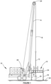
- the apparatus 10 comprises a rotation member 21 which includes a chuck drive 22 (not shown in Figure 2 ) for rotating the rod 12 (shown in broken lines), and a support, in the form of a raised access platform 24, for supporting the rotation member 21 over the well 20.
- a rotation member 21 which includes a chuck drive 22 (not shown in Figure 2 ) for rotating the rod 12 (shown in broken lines), and a support, in the form of a raised access platform 24, for supporting the rotation member 21 over the well 20.
- An embodiment of the apparatus 100 in which the chuck drive 220 can be seen in detail is shown in Figures 6 to 9 .
- the platform 24 and rotation member 21 are structurally independent from the rig 16.
- the rig 16 can therefore be used to raise and lower rods 12 into and out of the well 20, while the apparatus 10 is used for rotation of those rods 12.
- the rig 16 is not responsible for rotating the rods 12.
- structurally independent it is meant that the platform and chuck drive are not supported by the rig, but it should be understood that any incidental or indirect connection (such as that provided to resist rotation of the apparatus 10 relative to the rig 16) can be provided without departing from the scope of this embodiment.
- the platform 24 is positioned on the ground 26 beneath the crown 28 of the mast 14 and supports the chuck drive 22 from below. As such, rods 12 can be fed into the chuck drive 22, from above the chuck drive 22, and down into the well 20.
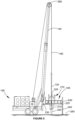
- access platform 240 is mounted to rig 160.
- the platform is coupled to the rig by connection 230.
- the connection 230 can be a hinge 230. This is more clearly seen in Figure 6 .
- the connections 230 are adapted to move about a rod attached to the rear of the rig 160 (not shown).
- the rig 160 can still be used to raise and lower rods 120 into and out of the well 200, while the apparatus 100 is used for rotation of those rods 120.
- Each rod 120 is supported from a mast 140 of a rig 160 by a line 180.
- the rod 120 is insertable into a well 200.
- the rig 160 is not responsible for rotating the rods 120.
- the rotation member 210 is supported by well 200.
- the rotation member 21 can be mounted directed to the well 20.
- the deck 32 as described can be arranged substantially around the rotation member for access.
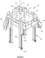
- the deck 32 can be raised and lowered on legs 34 to adjust the height of the deck 32 for positioning above wells 20 of various heights.
- the legs 34 may be extensible such that the deck has a height of up to 3500mm from the ground.
- the height of the well 20 when the platform 24 is positioned over the well 20 may be 2500mm, 3200mm or 3700mm, or any other height.
- Each leg 34 comprises a jack lift cylinder 36 and a threaded support 38.
- the threaded support 38 extends from a sleeve 40 down to a foot 42.
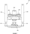
- platform 240 is shown for illustration purposes only and in use, the platform may actually be U-shaped to allow access to the rotation member 210. Also there are likely to be substantially bolts in the holes in the base plate of the drill module which are how it is attached to the components of the well which cannot be seen because they are obscured from view.
- Figure 8 is a cross-sectional side view of the rotation member 210 of Figure 7 .
- the hydraulic motors 250 operate to spin the bull gear (not shown) which is disposed in the component immediately beneath them (shown as a rectangle in cross section).
- the chuck 220 is thus rotated by the motors 250.
- Figures 8 and 9 are perspective top and bottom views for the sake of completion in viewing componentry.
- the step of positioning the apparatus over the well comprises mounting a rotation member to the well.
- a flushby rig 16 is setup next to a well 20.
- the flushby rig 16 flushes the well until it is determined that intervention is required.
- the mast 14 of the flushby rig 16 is then rotated away from the well 20 to provide clearance for positioning the apparatus 10 over the well 20. Is some cases, the mast 14 may be able to remain in position over the well 20 during positioning of the apparatus.
- the rotation member can then be mounted to the well optionally by attaching it to the stuffing box.
- the attachment may be by bolting it to the stuffing box.
- the apparatus is conveyed on site (e.g. by truck) to the vicinity of the well 20.
- the platform of the apparatus will typically be ⁇ in gauge' - in other words, the legs 34 of the platform will have been extended to a height such that the deck 32 will be higher than the well 20 when the apparatus 10 is positioned over the well 20.
- the deck 32 may be substantially U-shaped, so that the well 20 or wellhead is received between the arms of the 'U'.
- a crane or forklift can be used to lift the apparatus 10 into position on the ground, over the well 20.
- the distance from the front of the platform 24 to the centreline of the chuck drive 22 is 1000mm, and the distance from safety rails located around the sides and rear of the deck 32 to the centreline of the chuck drive 22 is 1800mm (i.e. overall length 2800mm and overall width 3600mm).
- the smaller 1000mm dimension to the front of the platform 24 ensures the platform 24 falls short of the rearmost point of the rig 16.
- a rig will provide a raised working platform at the rear. So the rearmost point of a rig in that case will be the rearmost point of the raised working platform.
- the apparatus 10 is hydraulically and electrically connected to the rig 16. This provides hydraulic and electric power to the apparatus 10 to facilitate, inter alia, adjustment of the legs 34.
- the controls of the rig 16 can be used to control the functions of the apparatus 10.
- the heights of the legs 34 can be adjusted until the deck 32 is level. Once level, if the platform is structurally independent of the rig, two rams 40 are extended from the apparatus 10 to the rig 16. Each ram 40 is configured to engage the rig 16 thereby to fix the apparatus 10 to the rig 16. The rams 40 can prevent rotation of the apparatus 40 in the event that the rods 12 catch in the well and resist rotation of the chuck drive 22. If the mast 14 has been rotated away from the well 20 to facilitate positioning of the apparatus 10 over the well 20, the mast 14 can now be rotated back into position above the well 20.
- one or more catwalks are attached to sides of the apparatus 10 from which rods 12 can be drawn.
- a catwalk may be position on both sides of the decks 32 (e.g. the sides of the deck 32 extending towards and away from the rig 16), or alternatively a catwalk may be positioned at the rear of the deck 32.
- Access ladders 50 are also provided optionally on the front side and rear side of the platform 24.
- the ladders 50 may be retractable for transporting the platform 24, or may be fixed in position at all times. If the platform is attached to the rig, the ladder is best located at the rear as shown in Figure 5 .
- the hook of the rig 16 which is attached to the winch or drawworks 46 of the rig 16, is used to collect rods 12 from the catwalks and position the rods 12 in the chuck drive 22.
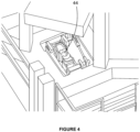
- the rods 12 can be held in position by a foot clamp 44 (see Figure 4 ). Foot clamps, such as foot clamp 44, will be known to the skilled person and need not be described in detail herein.
- the chuck drive 22 For receiving a rod 12, the chuck drive 22 will typically be at the top of its stroke - in other words, the chuck drive 22 will be at its highest position on the tracks 30.
- a rod 12 is inserted into the chuck drive 22 from above, the chuck drive clamps onto the rod 12 and the rod descends, under the weight of the rod string, supported from above by the rig 16 and under rotation imparted by the chuck drive 22.
- the lift cylinders in the tracks 30 of the chuck drive 22 may control the descent of the rod 12 so that it does not drop.
- the full length of the stroke of the chuck drive 22 from the top of the stroke to the bottom - in other words, the position of the chuck drive 22 furthest from the well 20 to the position of the chuck drive 22 closest to the well 20 - may be any desired length but will generally be selected to be an amount by which the length of the rod 12 is divisible.
- the stroke of the chuck drive 22 is 1500mm where the length of the rods 12 is 9000mm.
- four strokes of the chuck drive 22 are equivalent to the length of one rod 12.
- the rod 12 is held in position by foot clamp 44 and the feed of the rod 12 ceases. Therefore, the rods 12 are at all times attached to the platform. This provides a substantial safety benefit. If a rod 12 begins to be rejected by the well pressure, it will either be restrained in position by the foot clamp 44 or be held in the chuck drive 22. When clamped in the foot clamp 44, the rods will need to lift the entire weight of the apparatus 10 - which may be 5t, 6t or more - before being able to eject from the well 20. When held in the chuck drive 22, the rods 12 may drive the chuck drive 22 to the top of its stroke but once in that position, the rods 12 will again need to lift the entire weight of the apparatus 10 before being able to eject from the well 20.
- the winch 46 of the rig 16 may be advantageously provided with two-speed settings.
- the first, high-speed, setting is used during general lifting and drilling of the rods 12. Under this setting, called a ⁇ fine feed', the rate of lowering of the tube or rod 12 is controlled. Since the rods 12 generally descend under the weight of the string of rods 12, there is generally a large downward pressure applied by the rods 12 to the chuck drive 22 or to the winch 46. When that downward pressure reduces to lower than a predetermined pressure, it indicates that that hard rock or some other source of backpressure has been encountered. In this circumstance, the winch 46 automatically retracts the rod 12 so that the chuck drive 22 travels at least part way to the top of its stroke.
- the winch 46 then uses a second, low-speed or ⁇ weight-controlled feed', setting in which the rods 12 is inserted at a controlled, lower speed into the well 20.
- the term 'weight-controlled' is intended to encompass the use of weight as a trigger to moving to the slower feed rate, and also to encompass the use of the weight (i.e. a measurement of downward pressure of the rod or tube) to variably control a feed rate of the rod 12.
- the ⁇ predetermined pressure' may be set and measured using an existing ⁇ load on hook' sensor of the rig 16.
- the low-speed setting i.e. weight-controlled feed rate
- the winch pumps will stroke on and provide sufficient oil flow to hold back the weight on the hook of the rig 16.
- the winch brakes are then released, with no load movement due pressure applied by the oil flowing through the winch pumps, and the rods 12 can be lowered at a desired rate.
- predetermined pressure may be fixed and the rate of weight-controlled feed may similarly be fixed.
- the predetermined pressure may depend on the drilling or hole cleaning requirements of the work being performed.
- the operator may control the fluid flow through the winch pumps and thereby select the rate of weight-controlled feed of the rods 12.
- the apparatus 10 or rig 16 may automatically adjust the feed rate to maintain a particular downward pressure measurement and thereby control the rate of feed (i.e. the feed rate is controlled by the 'weight').
- a similar retraction and fine feed process may be used where the rods 12 begin to grab in the well 20, or where the density of the fluid returning from the well 20 increases to a degree that may damage the pumps.
- the rods are fed at fine feed rate (i.e. more slowly) so that comparatively more fluid is pumped into the well 20 as the rod 12 advances.
- the fine feed may be used without first withdrawing the rods 12 - in other words, the rod does not stop advancing, but simply advances at a slower rate while the pumps continue to pump at their previous rate.
- the lift cylinders mounted in the tracks 30 may be controlled to provide fine feed capabilities.
- the catwalks are removed from the platform 34, the hydraulics and electrics are disconnected form the rig 16 and the apparatus 10 is lifted off the well 20 and onto a truck for removal.
- the platform is moved to the inoperable position by folding it towards the body of the rig.
Landscapes
- Engineering & Computer Science (AREA)
- Geology (AREA)
- Life Sciences & Earth Sciences (AREA)
- Mining & Mineral Resources (AREA)
- Geochemistry & Mineralogy (AREA)
- Fluid Mechanics (AREA)
- Environmental & Geological Engineering (AREA)
- General Life Sciences & Earth Sciences (AREA)
- Physics & Mathematics (AREA)
- Mechanical Engineering (AREA)
- Earth Drilling (AREA)
- Forging (AREA)
- Soil Working Implements (AREA)
- Ultra Sonic Daignosis Equipment (AREA)
- Investigation Of Foundation Soil And Reinforcement Of Foundation Soil By Compacting Or Drainage (AREA)
- Geophysics And Detection Of Objects (AREA)
- Investigating Or Analyzing Materials By The Use Of Ultrasonic Waves (AREA)
- Investigating Or Analyzing Materials By The Use Of Magnetic Means (AREA)
Claims (10)
- Vorrichtung (10) zum Drehen eines Rohrs oder einer Stange (12), wobei das Rohr oder die Stange (12) von einem Mast (14) eines Bohrturms (16) getragen wird und zum Einführen in ein Bohrloch (20) oder eine Komponente des Bohrlochs (20) dient, wobei die Vorrichtung (10) ein Gewicht und Abmessungen aufweist, die einen Transport auf einer Fahrbahn und innerhalb der Grenzen einer Straße ermöglichen, die Vorrichtung (10) ein Rotationselement (21) zum Drehen des Rohrs oder der Stange umfasst, wobei das Rotationselement (21) an einer der Komponenten des Bohrlochs (20) an der Oberfläche befestigt ist oder an dem Bohrloch oder an dem Bohrloch durch eine Komponente des Bohrlochs angebracht ist die Vorrichtung ferner eine Zugangsplattform (24) umfasst, um Zugang zu dem Rotationselement (21) zu ermöglichen,das Rotationselement (21) an dem Bohrloch (20) oder an einer der Komponenten des Bohrlochs (20) so angebracht werden kann, dass das Rotationselement (21) im Gebrauch von dem Bohrloch (20) getragen wird, das Rohr oder die Stange (12) im Gebrauch in das Rotationselement (21) von oberhalb des Rotationselements (21) und in das Bohrloch (20) eingeführt wird, unddas Rohr oder die Stange (12), das/die in das Bohrloch (20) eingeführt wird, durch das Rotationselement (21) im Bohrloch (20) gehalten wird und die Vorrichtung so konfiguriert ist, dass das Gesamtgewicht der Vorrichtung (10) eine Gewichtskraft hat, die größer ist als eine nach oben gerichtete Kraft, die durch den Fluiddruck im Bohrloch auf das Rohr oder die Stange (12) ausgeübt wird.
- Vorrichtung nach Anspruch 1, wobei die Zugangsplattform (24) an einer Bohrinsel (16) befestigt ist.
- Vorrichtung nach Anspruch 1 oder 2, bei der die Zugangsplattform (24) im Gebrauch im Wesentlichen horizontal von einer Vielzahl von Beinen (34) getragen wird.
- Vorrichtung nach einem der Ansprüche 1 bis 4, wobei das Drehelement (21) eine erste Vorschubfunktion und eine zweite Vorschubfunktion zum Absenken des Rohrs oder der Stange (12) mit einer schnelleren bzw. einer langsameren Geschwindigkeit bereitstellt.
- Vorrichtung nach Anspruch 4, wobei, wenn eine von der Vorrichtung (10) oder der Bohranlage (16) gemessene Abwärtskraft des Rohrs oder der Stange (12) niedriger als ein vorbestimmter Schwellenwert ist, das Rotationselement (21) ansteigt, um das Rohr oder die Stange (12) zumindest teilweise aus dem Bohrloch (20) zurückzuziehen, und die zweite Vorschubfunktion verwendet wird, um das Rohr oder die Stange (12) mit einer langsameren Geschwindigkeit abzusenken.
- Vorrichtung nach einem der Ansprüche 1 bis 5, wobei das Rotationselement (21) einen Hub aufweist, über den sich das Rotationselement (21) im Gebrauch mit dem Rohr oder der Stange (12) nach unten in Richtung des Bohrlochs (20) bewegt, bevor es zum oberen Ende des Hubs zurückkehrt.
- Vorrichtung nach einem der Ansprüche 1 bis 6, wobei das Rohr oder die Stange (12) Teil eines Rohr- oder Stangenstrangs ist, wobei die Vorrichtung (10) ferner Haltemittel (44) zum Halten des Rohr- oder Stangenstrangs umfasst, während ein weiteres Rohr oder eine weitere Stange (12) daran befestigt wird.
- Verfahren zum Einführen eines Rohrs oder einer Stange (12) in ein Bohrloch (20) oder eine Komponente des Bohrlochs (20), umfassenda. Positionierung eines Bohrgeräts (16) in der Nähe des Bohrlochs (20)b. Anbringen eines Rotationselements (21) an dem Bohrloch (20) oder an einem der Bestandteile des Bohrlochs (20), so dass es von dem Bohrloch (20) getragen wirdc. Absenken eines Rohrs oder einer Stange (12) in Richtung des Bohrlochs (20) oder auf eine der Komponenten des Bohrlochs (20) unter Verwendung der Vorrichtung (16) und gleichzeitiges Drehen des Rohrs oder der Stange unter Verwendung des Rotationselements (21), wobeid. das Rotationselement (21) im Gebrauch von dem Bohrloch (20) getragen wird, wobei das Rohr oder die Stange (12) im Gebrauch in das Rotationselement (21) von oberhalb des Rotationselements (21) und in das Bohrloch (20) eingeführt wird, unde. das in das Bohrloch (20) eingeführte Rohr oder die Stange (12) durch das Rotationselement (21) im Bohrloch (20) gehalten wird und die Vorrichtung so konfiguriert ist, dass das Gesamtgewicht der Vorrichtung (10) eine Gewichtskraft aufweist, die größer ist als eine nach oben gerichtete Kraft, die durch den Fluiddruck im Bohrloch auf das Rohr oder die Stange (12) ausgeübt wird.
- Verfahren nach Anspruch 8 unter Verwendung einer Winde einer Bohranlage (16), eines Rohr- oder Stangenstrangs, der durch das Rotationselement (21) in das Bohrloch (20) abgesenkt wird, wobei das Verfahren Folgendes umfassta. Absenken des Strangs mit einer ersten Geschwindigkeit durch das Rotationselement (21);b. Messen eines "Gewichts am Haken" der Winde;c. zumindest teilweises Zurückziehen des Strangs von dem Rotationselement (21), wenn das gemessene "Gewicht am Haken" anzeigt, dass der Rohr- oder Stangenstrang einen Druck auf das Bohrloch (20) ausübt, der einen vorbestimmten Druck übersteigt; undd. Absenken des Strangs mit einer zweiten Geschwindigkeit, die niedriger ist als die erste Geschwindigkeit, durch das Rotationselement (21), um das Absenken des Rohr- oder Stangenstrangs in das Bohrloch (20) zu steuern.
- Verfahren nach Anspruch 9, wobei der Messschritt durchgeführt wird, während zumindest der erste Absenkschritt a. durchgeführt wird.
Priority Applications (1)
| Application Number | Priority Date | Filing Date | Title |
|---|---|---|---|
| HRP20240353TT HRP20240353T1 (hr) | 2014-04-28 | 2015-04-28 | Naprava za rotaciju šipke |
Applications Claiming Priority (2)
| Application Number | Priority Date | Filing Date | Title |
|---|---|---|---|
| AU2014901529A AU2014901529A0 (en) | 2014-04-28 | Apparatuses and Methods for raising or lowering a tube or rod | |
| PCT/AU2015/000252 WO2015164911A1 (en) | 2014-04-28 | 2015-04-28 | Rod rotation apparatus |
Publications (4)
| Publication Number | Publication Date |
|---|---|
| EP3137719A1 EP3137719A1 (de) | 2017-03-08 |
| EP3137719A4 EP3137719A4 (de) | 2017-05-10 |
| EP3137719C0 EP3137719C0 (de) | 2023-12-20 |
| EP3137719B1 true EP3137719B1 (de) | 2023-12-20 |
Family
ID=54357908
Family Applications (1)
| Application Number | Title | Priority Date | Filing Date |
|---|---|---|---|
| EP15785398.7A Active EP3137719B1 (de) | 2014-04-28 | 2015-04-28 | Stangenrotationsvorrichtung |
Country Status (9)
| Country | Link |
|---|---|
| US (1) | US10626685B2 (de) |
| EP (1) | EP3137719B1 (de) |
| CN (1) | CN106255800B (de) |
| AU (2) | AU2015252751A1 (de) |
| CA (1) | CA2944514C (de) |
| ES (1) | ES2967358T3 (de) |
| HR (1) | HRP20240353T1 (de) |
| HU (1) | HUE065562T2 (de) |
| WO (1) | WO2015164911A1 (de) |
Families Citing this family (7)
| Publication number | Priority date | Publication date | Assignee | Title |
|---|---|---|---|---|
| AU2017200699B2 (en) * | 2016-02-15 | 2021-07-01 | Joy Global Surface Mining Inc | Adaptive leveling control system |
| CN110300834B (zh) | 2017-01-18 | 2022-04-29 | 米尼克斯Crc有限公司 | 一种移动式连续油管钻井装置 |
| US11814948B2 (en) | 2017-12-31 | 2023-11-14 | Walter Phillips | Apparatus and method for detecting the rotation of a rod-string in a wellbore |
| CN109723397B (zh) * | 2019-02-27 | 2023-10-20 | 上海金泰工程机械有限公司 | 用于超深作业的双动力头钻具续接结构及钻机 |
| US11525351B2 (en) * | 2019-04-11 | 2022-12-13 | Walter Phillips | Wellbore friction measurement, method and apparatus |
| CN111305789B (zh) * | 2020-02-25 | 2022-05-03 | 中国海洋石油集团有限公司 | 一种热采防漏失循环滑套 |
| FI3960980T3 (fi) | 2020-09-01 | 2024-01-18 | Sandvik Mining & Construction Oy | Maatuki liikkuvaan porauslaitteistoon |
Citations (1)
| Publication number | Priority date | Publication date | Assignee | Title |
|---|---|---|---|---|
| US2617500A (en) * | 1948-07-16 | 1952-11-11 | Cardwell Mfg Company Inc | Portable drilling rig |
Family Cites Families (20)
| Publication number | Priority date | Publication date | Assignee | Title |
|---|---|---|---|---|
| GB399468A (en) * | 1931-10-19 | 1933-10-02 | Nat Supply Corp | Well drilling equipment for handling drill pipe and casing in high pressure wells |
| US2080804A (en) | 1935-04-30 | 1937-05-18 | John E Brantly | Well drilling control system |
| US2314323A (en) * | 1941-01-09 | 1943-03-23 | George E Failing Supply Compan | Rat-hole drilling attachment for rotary drilling rigs |
| US2594847A (en) * | 1947-12-29 | 1952-04-29 | Shell Dev | Drilling rig substructure |
| US4021978A (en) * | 1973-10-17 | 1977-05-10 | Cabot Corporation | Mast assembly |
| FR2292850A1 (fr) * | 1974-11-26 | 1976-06-25 | Airaudo Antonin | Machine de forage ou de sondage a mat ou fleche de longueur variable |
| US4326602A (en) * | 1979-01-05 | 1982-04-27 | Houston Tong Services, Inc. | Portable stabbing board |
| US4290495A (en) * | 1979-06-18 | 1981-09-22 | Hydra-Rig, Inc. | Portable workover rig with extendable mast substructure, platform mounted drawworks and adjustable wellhead anchor |
| US6158516A (en) * | 1998-12-02 | 2000-12-12 | Cudd Pressure Control, Inc. | Combined drilling apparatus and method |
| US6412576B1 (en) * | 1999-10-16 | 2002-07-02 | William J. Meiners | Methods and apparatus for subterranean drilling utilizing a top drive |
| GB0004354D0 (en) * | 2000-02-25 | 2000-04-12 | Wellserv Plc | Apparatus and method |
| US6412554B1 (en) * | 2000-03-14 | 2002-07-02 | Weatherford/Lamb, Inc. | Wellbore circulation system |
| US6681894B1 (en) | 2002-10-26 | 2004-01-27 | Robert P. Fanguy | Portable well head work platform |
| US7226037B2 (en) * | 2004-08-25 | 2007-06-05 | Key Energy Services, Inc. | System for assuring engagement of a hydromatic brake on a drilling or well service rig |
| US7917293B2 (en) * | 2007-09-05 | 2011-03-29 | Key Energy Services, Llc | Method and system for controlling a well service rig based on load data |
| US8844652B2 (en) * | 2007-10-23 | 2014-09-30 | Weatherford/Lamb, Inc. | Interlocking low profile rotating control device |
| US8915310B2 (en) * | 2012-06-21 | 2014-12-23 | Superior Energy Services—North America Services, Inc. | Long lateral completion system and method |
| ITTO20120863A1 (it) * | 2012-10-04 | 2014-04-05 | Drillmec Spa | Impianto di trivellazione mobile. |
| KR102225073B1 (ko) * | 2012-10-22 | 2021-03-10 | 퀵실버 드릴링 테크놀로지스, 엘엘씨 | 자동화된 파이프 트립핑 장치 및 방법 |
| CA2833730A1 (en) * | 2012-11-19 | 2014-05-19 | Key Energy Services, Llc | Mechanized and automated well service rig system |
-
2015
- 2015-04-28 ES ES15785398T patent/ES2967358T3/es active Active
- 2015-04-28 HR HRP20240353TT patent/HRP20240353T1/hr unknown
- 2015-04-28 HU HUE15785398A patent/HUE065562T2/hu unknown
- 2015-04-28 WO PCT/AU2015/000252 patent/WO2015164911A1/en not_active Ceased
- 2015-04-28 CA CA2944514A patent/CA2944514C/en active Active
- 2015-04-28 EP EP15785398.7A patent/EP3137719B1/de active Active
- 2015-04-28 AU AU2015252751A patent/AU2015252751A1/en not_active Abandoned
- 2015-04-28 CN CN201580022408.1A patent/CN106255800B/zh active Active
- 2015-04-28 US US15/307,202 patent/US10626685B2/en active Active
-
2019
- 2019-09-30 AU AU2019240550A patent/AU2019240550B2/en active Active
Patent Citations (1)
| Publication number | Priority date | Publication date | Assignee | Title |
|---|---|---|---|---|
| US2617500A (en) * | 1948-07-16 | 1952-11-11 | Cardwell Mfg Company Inc | Portable drilling rig |
Also Published As
| Publication number | Publication date |
|---|---|
| CA2944514C (en) | 2022-10-04 |
| AU2019240550B2 (en) | 2021-09-02 |
| AU2015252751A1 (en) | 2016-10-20 |
| ES2967358T3 (es) | 2024-04-29 |
| EP3137719A4 (de) | 2017-05-10 |
| CN106255800B (zh) | 2021-06-25 |
| CN106255800A (zh) | 2016-12-21 |
| WO2015164911A1 (en) | 2015-11-05 |
| EP3137719C0 (de) | 2023-12-20 |
| CA2944514A1 (en) | 2015-11-05 |
| HUE065562T2 (hu) | 2024-06-28 |
| HRP20240353T1 (hr) | 2024-06-07 |
| US10626685B2 (en) | 2020-04-21 |
| AU2019240550A1 (en) | 2019-10-17 |
| US20170044849A1 (en) | 2017-02-16 |
| EP3137719A1 (de) | 2017-03-08 |
Similar Documents
| Publication | Publication Date | Title |
|---|---|---|
| AU2019240550B2 (en) | Rod Rotation Apparatus | |
| CA2572663C (en) | Automated system for positioning and supporting the work platform of a mobile workover and well-servicing rig | |
| CA2701102C (en) | Automated system for positioning and supporting the work platform of a mobile workover and well-servicing rig | |
| US8006751B2 (en) | Automated system for positioning and supporting the work platform of a mobile workover and well-servicing rig | |
| US10323466B2 (en) | Drilling rig and method of use | |
| US10113377B2 (en) | Drive systems for use with long lateral completion systems and methods | |
| CA2877524C (en) | Mast and guy wire systems for use with long lateral completion systems and methods | |
| US7527100B2 (en) | Method and apparatus for cutting and removal of pipe from wells | |
| US20170275952A1 (en) | Support Apparatus for Supporting Down Hole Rotary Tools | |
| WO2011135541A2 (en) | Modular multi-workstring system for subsea intervention and abandonment operations | |
| CA2944722C (en) | Rig mast and related components | |
| CN111963070B (zh) | 一种预应力钢绞线探矿钻机液压支架 | |
| US20170314345A1 (en) | Assemblies and methods for inserting and removing tubulars from a wellbore | |
| CA2537511C (en) | Mobile snubbing system | |
| CA2877534C (en) | Long lateral completion system and method for pipe handling | |
| CA2877530C (en) | Mobile rig and method |
Legal Events
| Date | Code | Title | Description |
|---|---|---|---|
| REG | Reference to a national code |
Ref country code: HR Ref legal event code: TUEP Ref document number: P20240353T Country of ref document: HR |
|
| STAA | Information on the status of an ep patent application or granted ep patent |
Free format text: STATUS: THE INTERNATIONAL PUBLICATION HAS BEEN MADE |
|
| PUAI | Public reference made under article 153(3) epc to a published international application that has entered the european phase |
Free format text: ORIGINAL CODE: 0009012 |
|
| STAA | Information on the status of an ep patent application or granted ep patent |
Free format text: STATUS: REQUEST FOR EXAMINATION WAS MADE |
|
| 17P | Request for examination filed |
Effective date: 20161102 |
|
| AK | Designated contracting states |
Kind code of ref document: A1 Designated state(s): AL AT BE BG CH CY CZ DE DK EE ES FI FR GB GR HR HU IE IS IT LI LT LU LV MC MK MT NL NO PL PT RO RS SE SI SK SM TR |
|
| AX | Request for extension of the european patent |
Extension state: BA ME |
|
| A4 | Supplementary search report drawn up and despatched |
Effective date: 20170412 |
|
| RIC1 | Information provided on ipc code assigned before grant |
Ipc: E21B 15/00 20060101ALI20170406BHEP Ipc: E21B 7/02 20060101ALI20170406BHEP Ipc: B66D 5/00 20060101ALI20170406BHEP Ipc: E21B 19/00 20060101AFI20170406BHEP Ipc: E21B 3/04 20060101ALI20170406BHEP Ipc: B66F 11/04 20060101ALI20170406BHEP Ipc: E21B 19/24 20060101ALI20170406BHEP Ipc: E21B 19/08 20060101ALI20170406BHEP Ipc: E21B 17/00 20060101ALI20170406BHEP |
|
| DAV | Request for validation of the european patent (deleted) | ||
| DAX | Request for extension of the european patent (deleted) | ||
| STAA | Information on the status of an ep patent application or granted ep patent |
Free format text: STATUS: EXAMINATION IS IN PROGRESS |
|
| 17Q | First examination report despatched |
Effective date: 20171219 |
|
| GRAP | Despatch of communication of intention to grant a patent |
Free format text: ORIGINAL CODE: EPIDOSNIGR1 |
|
| STAA | Information on the status of an ep patent application or granted ep patent |
Free format text: STATUS: GRANT OF PATENT IS INTENDED |
|
| INTG | Intention to grant announced |
Effective date: 20211130 |
|
| RAP3 | Party data changed (applicant data changed or rights of an application transferred) |
Owner name: DRILL RIG SPARES PTY LTD |
|
| STAA | Information on the status of an ep patent application or granted ep patent |
Free format text: STATUS: THE APPLICATION IS DEEMED TO BE WITHDRAWN |
|
| 18D | Application deemed to be withdrawn |
Effective date: 20220412 |
|
| 18RA | Request filed for re-establishment of rights before grant |
Effective date: 20221025 |
|
| GRAS | Grant fee paid |
Free format text: ORIGINAL CODE: EPIDOSNIGR3 |
|
| STAA | Information on the status of an ep patent application or granted ep patent |
Free format text: STATUS: GRANT OF PATENT IS INTENDED |
|
| GRAA | (expected) grant |
Free format text: ORIGINAL CODE: 0009210 |
|
| STAA | Information on the status of an ep patent application or granted ep patent |
Free format text: STATUS: THE PATENT HAS BEEN GRANTED |
|
| D18D | Application deemed to be withdrawn (deleted) | ||
| AK | Designated contracting states |
Kind code of ref document: B1 Designated state(s): AL AT BE BG CH CY CZ DE DK EE ES FI FR GB GR HR HU IE IS IT LI LT LU LV MC MK MT NL NO PL PT RO RS SE SI SK SM TR |
|
| REG | Reference to a national code |
Ref country code: CH Ref legal event code: EP |
|
| REG | Reference to a national code |
Ref country code: DE Ref legal event code: R096 Ref document number: 602015087015 Country of ref document: DE |
|
| REG | Reference to a national code |
Ref country code: IE Ref legal event code: FG4D |
|
| U01 | Request for unitary effect filed |
Effective date: 20240108 |
|
| U07 | Unitary effect registered |
Designated state(s): AT BE BG DE DK EE FI FR IT LT LU LV MT NL PT SE SI Effective date: 20240116 |
|
| PG25 | Lapsed in a contracting state [announced via postgrant information from national office to epo] |
Ref country code: GR Free format text: LAPSE BECAUSE OF FAILURE TO SUBMIT A TRANSLATION OF THE DESCRIPTION OR TO PAY THE FEE WITHIN THE PRESCRIBED TIME-LIMIT Effective date: 20240321 |
|
| REG | Reference to a national code |
Ref country code: ES Ref legal event code: FG2A Ref document number: 2967358 Country of ref document: ES Kind code of ref document: T3 Effective date: 20240429 |
|
| PG25 | Lapsed in a contracting state [announced via postgrant information from national office to epo] |
Ref country code: GR Free format text: LAPSE BECAUSE OF FAILURE TO SUBMIT A TRANSLATION OF THE DESCRIPTION OR TO PAY THE FEE WITHIN THE PRESCRIBED TIME-LIMIT Effective date: 20240321 |
|
| REG | Reference to a national code |
Ref country code: HR Ref legal event code: ODRP Ref document number: P20240353T Country of ref document: HR Payment date: 20240419 Year of fee payment: 10 |
|
| U20 | Renewal fee for the european patent with unitary effect paid |
Year of fee payment: 10 Effective date: 20240424 |
|
| PG25 | Lapsed in a contracting state [announced via postgrant information from national office to epo] |
Ref country code: RS Free format text: LAPSE BECAUSE OF FAILURE TO SUBMIT A TRANSLATION OF THE DESCRIPTION OR TO PAY THE FEE WITHIN THE PRESCRIBED TIME-LIMIT Effective date: 20231220 Ref country code: NO Free format text: LAPSE BECAUSE OF FAILURE TO SUBMIT A TRANSLATION OF THE DESCRIPTION OR TO PAY THE FEE WITHIN THE PRESCRIBED TIME-LIMIT Effective date: 20240320 |
|
| REG | Reference to a national code |
Ref country code: HR Ref legal event code: T1PR Ref document number: P20240353 Country of ref document: HR |
|
| REG | Reference to a national code |
Ref country code: HU Ref legal event code: AG4A Ref document number: E065562 Country of ref document: HU |
|
| PG25 | Lapsed in a contracting state [announced via postgrant information from national office to epo] |
Ref country code: IS Free format text: LAPSE BECAUSE OF FAILURE TO SUBMIT A TRANSLATION OF THE DESCRIPTION OR TO PAY THE FEE WITHIN THE PRESCRIBED TIME-LIMIT Effective date: 20240420 |
|
| PG25 | Lapsed in a contracting state [announced via postgrant information from national office to epo] |
Ref country code: CZ Free format text: LAPSE BECAUSE OF FAILURE TO SUBMIT A TRANSLATION OF THE DESCRIPTION OR TO PAY THE FEE WITHIN THE PRESCRIBED TIME-LIMIT Effective date: 20231220 |
|
| PG25 | Lapsed in a contracting state [announced via postgrant information from national office to epo] |
Ref country code: SK Free format text: LAPSE BECAUSE OF FAILURE TO SUBMIT A TRANSLATION OF THE DESCRIPTION OR TO PAY THE FEE WITHIN THE PRESCRIBED TIME-LIMIT Effective date: 20231220 |
|
| PG25 | Lapsed in a contracting state [announced via postgrant information from national office to epo] |
Ref country code: SM Free format text: LAPSE BECAUSE OF FAILURE TO SUBMIT A TRANSLATION OF THE DESCRIPTION OR TO PAY THE FEE WITHIN THE PRESCRIBED TIME-LIMIT Effective date: 20231220 Ref country code: SK Free format text: LAPSE BECAUSE OF FAILURE TO SUBMIT A TRANSLATION OF THE DESCRIPTION OR TO PAY THE FEE WITHIN THE PRESCRIBED TIME-LIMIT Effective date: 20231220 Ref country code: RO Free format text: LAPSE BECAUSE OF FAILURE TO SUBMIT A TRANSLATION OF THE DESCRIPTION OR TO PAY THE FEE WITHIN THE PRESCRIBED TIME-LIMIT Effective date: 20231220 Ref country code: IS Free format text: LAPSE BECAUSE OF FAILURE TO SUBMIT A TRANSLATION OF THE DESCRIPTION OR TO PAY THE FEE WITHIN THE PRESCRIBED TIME-LIMIT Effective date: 20240420 Ref country code: CZ Free format text: LAPSE BECAUSE OF FAILURE TO SUBMIT A TRANSLATION OF THE DESCRIPTION OR TO PAY THE FEE WITHIN THE PRESCRIBED TIME-LIMIT Effective date: 20231220 |
|
| PG25 | Lapsed in a contracting state [announced via postgrant information from national office to epo] |
Ref country code: PL Free format text: LAPSE BECAUSE OF FAILURE TO SUBMIT A TRANSLATION OF THE DESCRIPTION OR TO PAY THE FEE WITHIN THE PRESCRIBED TIME-LIMIT Effective date: 20231220 |
|
| PG25 | Lapsed in a contracting state [announced via postgrant information from national office to epo] |
Ref country code: PL Free format text: LAPSE BECAUSE OF FAILURE TO SUBMIT A TRANSLATION OF THE DESCRIPTION OR TO PAY THE FEE WITHIN THE PRESCRIBED TIME-LIMIT Effective date: 20231220 |
|
| REG | Reference to a national code |
Ref country code: DE Ref legal event code: R097 Ref document number: 602015087015 Country of ref document: DE |
|
| PLBE | No opposition filed within time limit |
Free format text: ORIGINAL CODE: 0009261 |
|
| STAA | Information on the status of an ep patent application or granted ep patent |
Free format text: STATUS: NO OPPOSITION FILED WITHIN TIME LIMIT |
|
| PG25 | Lapsed in a contracting state [announced via postgrant information from national office to epo] |
Ref country code: MC Free format text: LAPSE BECAUSE OF FAILURE TO SUBMIT A TRANSLATION OF THE DESCRIPTION OR TO PAY THE FEE WITHIN THE PRESCRIBED TIME-LIMIT Effective date: 20231220 |
|
| 26N | No opposition filed |
Effective date: 20240923 |
|
| PG25 | Lapsed in a contracting state [announced via postgrant information from national office to epo] |
Ref country code: MC Free format text: LAPSE BECAUSE OF FAILURE TO SUBMIT A TRANSLATION OF THE DESCRIPTION OR TO PAY THE FEE WITHIN THE PRESCRIBED TIME-LIMIT Effective date: 20231220 |
|
| REG | Reference to a national code |
Ref country code: CH Ref legal event code: PL |
|
| PG25 | Lapsed in a contracting state [announced via postgrant information from national office to epo] |
Ref country code: CH Free format text: LAPSE BECAUSE OF NON-PAYMENT OF DUE FEES Effective date: 20240430 |
|
| PG25 | Lapsed in a contracting state [announced via postgrant information from national office to epo] |
Ref country code: IE Free format text: LAPSE BECAUSE OF NON-PAYMENT OF DUE FEES Effective date: 20240428 |
|
| REG | Reference to a national code |
Ref country code: HR Ref legal event code: ODRP Ref document number: P20240353 Country of ref document: HR Payment date: 20250417 Year of fee payment: 11 |
|
| U20 | Renewal fee for the european patent with unitary effect paid |
Year of fee payment: 11 Effective date: 20250425 |
|
| PGFP | Annual fee paid to national office [announced via postgrant information from national office to epo] |
Ref country code: ES Payment date: 20250529 Year of fee payment: 11 Ref country code: GB Payment date: 20250423 Year of fee payment: 11 |
|
| PGFP | Annual fee paid to national office [announced via postgrant information from national office to epo] |
Ref country code: HR Payment date: 20250417 Year of fee payment: 11 |
|
| PGFP | Annual fee paid to national office [announced via postgrant information from national office to epo] |
Ref country code: TR Payment date: 20250422 Year of fee payment: 11 |
|
| PG25 | Lapsed in a contracting state [announced via postgrant information from national office to epo] |
Ref country code: CY Free format text: LAPSE BECAUSE OF FAILURE TO SUBMIT A TRANSLATION OF THE DESCRIPTION OR TO PAY THE FEE WITHIN THE PRESCRIBED TIME-LIMIT; INVALID AB INITIO Effective date: 20150428 |
|
| PGFP | Annual fee paid to national office [announced via postgrant information from national office to epo] |
Ref country code: HU Payment date: 20251008 Year of fee payment: 11 |