EP3137836B1 - Échangeur de chaleur amélioré - Google Patents
Échangeur de chaleur amélioré Download PDFInfo
- Publication number
- EP3137836B1 EP3137836B1 EP15721968.4A EP15721968A EP3137836B1 EP 3137836 B1 EP3137836 B1 EP 3137836B1 EP 15721968 A EP15721968 A EP 15721968A EP 3137836 B1 EP3137836 B1 EP 3137836B1
- Authority
- EP
- European Patent Office
- Prior art keywords
- heat exchanger
- manifold
- tubes
- fins
- distance
- Prior art date
- Legal status (The legal status is an assumption and is not a legal conclusion. Google has not performed a legal analysis and makes no representation as to the accuracy of the status listed.)
- Active
Links
Images

Classifications
-
- F—MECHANICAL ENGINEERING; LIGHTING; HEATING; WEAPONS; BLASTING
- F28—HEAT EXCHANGE IN GENERAL
- F28D—HEAT-EXCHANGE APPARATUS, NOT PROVIDED FOR IN ANOTHER SUBCLASS, IN WHICH THE HEAT-EXCHANGE MEDIA DO NOT COME INTO DIRECT CONTACT
- F28D1/00—Heat-exchange apparatus having stationary conduit assemblies for one heat-exchange medium only, the media being in contact with different sides of the conduit wall, in which the other heat-exchange medium is a large body of fluid, e.g. domestic or motor car radiators
- F28D1/02—Heat-exchange apparatus having stationary conduit assemblies for one heat-exchange medium only, the media being in contact with different sides of the conduit wall, in which the other heat-exchange medium is a large body of fluid, e.g. domestic or motor car radiators with heat-exchange conduits immersed in the body of fluid
- F28D1/04—Heat-exchange apparatus having stationary conduit assemblies for one heat-exchange medium only, the media being in contact with different sides of the conduit wall, in which the other heat-exchange medium is a large body of fluid, e.g. domestic or motor car radiators with heat-exchange conduits immersed in the body of fluid with tubular conduits
- F28D1/053—Heat-exchange apparatus having stationary conduit assemblies for one heat-exchange medium only, the media being in contact with different sides of the conduit wall, in which the other heat-exchange medium is a large body of fluid, e.g. domestic or motor car radiators with heat-exchange conduits immersed in the body of fluid with tubular conduits the conduits being straight
- F28D1/0535—Heat-exchange apparatus having stationary conduit assemblies for one heat-exchange medium only, the media being in contact with different sides of the conduit wall, in which the other heat-exchange medium is a large body of fluid, e.g. domestic or motor car radiators with heat-exchange conduits immersed in the body of fluid with tubular conduits the conduits being straight the conduits having a non-circular cross-section
- F28D1/05366—Assemblies of conduits connected to common headers, e.g. core type radiators
-
- F—MECHANICAL ENGINEERING; LIGHTING; HEATING; WEAPONS; BLASTING
- F25—REFRIGERATION OR COOLING; COMBINED HEATING AND REFRIGERATION SYSTEMS; HEAT PUMP SYSTEMS; MANUFACTURE OR STORAGE OF ICE; LIQUEFACTION SOLIDIFICATION OF GASES
- F25B—REFRIGERATION MACHINES, PLANTS OR SYSTEMS; COMBINED HEATING AND REFRIGERATION SYSTEMS; HEAT PUMP SYSTEMS
- F25B39/00—Evaporators; Condensers
-
- F—MECHANICAL ENGINEERING; LIGHTING; HEATING; WEAPONS; BLASTING
- F28—HEAT EXCHANGE IN GENERAL
- F28F—DETAILS OF HEAT-EXCHANGE AND HEAT-TRANSFER APPARATUS, OF GENERAL APPLICATION
- F28F1/00—Tubular elements; Assemblies of tubular elements
- F28F1/10—Tubular elements and assemblies thereof with means for increasing heat-transfer area, e.g. with fins, with projections, with recesses
- F28F1/12—Tubular elements and assemblies thereof with means for increasing heat-transfer area, e.g. with fins, with projections, with recesses the means being only outside the tubular element
-
- F—MECHANICAL ENGINEERING; LIGHTING; HEATING; WEAPONS; BLASTING
- F28—HEAT EXCHANGE IN GENERAL
- F28F—DETAILS OF HEAT-EXCHANGE AND HEAT-TRANSFER APPARATUS, OF GENERAL APPLICATION
- F28F2265/00—Safety or protection arrangements; Arrangements for preventing malfunction
- F28F2265/26—Safety or protection arrangements; Arrangements for preventing malfunction for allowing differential expansion between elements
Definitions
- This invention relates generally to heat exchangers and, more particularly, to microchannel heat exchangers for use in air conditioning and refrigeration vapor compression systems.
- Heating, ventilation, air conditioning and refrigeration (HVAC&R) systems include heat exchangers to reject or accept heat between the refrigerant circulating within the system and surroundings.
- a microchannel heat exchanger includes two or more containment forms, such as tubes, through which a cooling or heating fluid (i.e. refrigerant or a glycol solution) is circulated.
- the tubes typically have a flattened cross-section and multiple parallel flow channels. Fins are typically arranged to extend between the tubes to air in the transfer of thermal energy between the heating/cooling fluid and the surrounding environment.
- the fins have a corrugated pattern, incorporate louvers to boost heat transfer, and are typically secured to the tubes via brazing.
- a thermal stress acts on the region of the heat exchanger at the joints between the heat exchanger tubes and adjacent headers. This is because a header of the heat exchanger thermally expands by exposure to a high temperature, while the fins coupled to the heat exchanger tubes remain at a lower temperature. Therefore, each of the joints between the high temperature manifold and the low temperature tubes is subject to a high stress alternating between tensile and compressive stress due to simultaneous occurrence of expansion and contraction at each of the joints. As a result, cracking of a portion of the heat exchanger may occur, resulting in a decreased heat exchanger fatigue life.
- JP 2005 061685 A shows a heat exchanger including a heat exchanger tube with a fin attached to the heat exchanger tube.
- a heat exchanger including a first manifold and a second manifold.
- the first manifold and the second manifold are separated from one another.
- a plurality of heat exchanger tubes is arranged in a spaced parallel relationship.
- the heat exchanger tubes fluidly couple the first manifold and the second manifold.
- a plurality of fins is attached to the plurality of heat exchanger tubes such that a first end of each fin is spaced apart from the first manifold by a first distance.
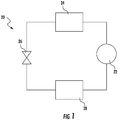
- FIG. 1 An example of a basic vapor compression system 20 is illustrated in FIG. 1 , including a compressor 22, configured to compress a refrigerant and deliver it downstream to a condenser 24. From the condenser 24, the cooled liquid refrigerant passes through an expansion device 26 to an evaporator 28. From the evaporator 28, the refrigerant is returned to the compressor 22 to complete the closed-loop refrigerant circuit.
- the heat exchanger 30 is a single tube bank microchannel heat exchanger 30; however, microchannel heat exchangers having mulitple tube banks, as well as other types of heat exchangers, such as tube and fin heat exchangers for example, are within the scope of the invention.
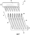
- the heat exchanger 30 includes a first manifold or header 32, a second manifold or header 34 spaced apart from the first manifold 32, and a plurality of heat exchange tubes 36 extending in a spaced parallel relationship between and connecting the first manifold 32 and the second manifold 34.
- the heat exchanger 30 may be used as either a condenser 24 or an evaporator 28 in the vapor compression system 20.
- the manifolds 32, 34 are oriented generally horizontally and tubes 36 extend vertically between the two headers 32, 34, as shown in FIG. 2 .
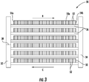
- the headers 32, 34 are typically vertically oriented such that the tubes 36 extend generally horizontally through the heat exchanger 30, as shown in FIG. 3 .
- the heat exchanger 30 may be configured in a single pass arrangement, such that refrigerant flows from the first header 32 to the second header 34 through the plurality of heat exchanger tubes 36 in the flow direction indicated by arrow B ( FIG. 2 ).
- the heat exchanger 30 is configured in a multi-pass flow arrangement.
- fluid is configured to flow from the first manifold 32 to the second manifold 34, in the direction indicated by arrow B, through a first portion of the heat exchanger tubes 36, and back to the first manifold 32, in the direction indicated by arrow C, through a second portion of the heat exchanger tubes 36.
- the heat exchanger 30 may additionally include guard or "dummy" tubes (not shown) extending between its first and second manifolds 32, 34 at the sides of the tube bank. These "dummy" tubes do not convey refrigerant flow, but add structural support to the tube bank.
- each heat exchange tube 36 comprises a flattened heat exchange tube having a leading edge 40, a trailing edge 42, a first surface 44, and a second surface 46.
- the leading edge 40 of each heat exchanger tube 36 is upstream of its respective trailing edge 42 with respect to an airflow A through the heat exchanger 36.
- the interior flow passage of each heat exchange tube 36 may be divided by interior walls into a plurality of discrete flow channels 48 that extend over the length of the tubes 36 from an inlet end to an outlet end and establish fluid communication between the respective first and second manifolds 32, 34.
- the flow channels 48 may have a circular cross-section, a rectangular cross-section, a trapezoidal cross-section, a triangular cross-section, or another non-circular cross-section.
- the heat exchange tubes 36 including the discrete flow channels 48 may be formed using known techniques and materials, including, but not limited to, extruded or folded.
- a plurality of heat transfer fins 50 may be disposed between and rigidly attached, usually by a furnace braze process, to the heat exchange tubes 36, in order to enhance external heat transfer and provide structural rigidity to the heat exchanger 30.
- Each folded fin 50 is formed from a plurality of connected strips or a single continuous strip of fin material tightly folded in a ribbon-like serpentine fashion thereby providing a plurality of closely spaced fins 52 that extend generally orthogonal to the flattened heat exchange tubes 36.
- Heat exchange between the fluid within the heat exchanger tubes 36 and air flow A occurs through the outside surfaces 44, 46 of the heat exchange tubes 36 collectively forming the primary heat exchange surface, and also through the heat exchange surface of the fins 52 of the folded fin 50, which form the secondary heat exchange surface.
- the fins mounted to each of the plurality of heat exchanger tubes extend over the full length of the tubes, from the first header to the second header.
- the fins 50 of the heat exchanger 30 illustrated and described herein, however, are shorter than the tubes 36.
- the fins 50 are mounted near the center of each tube 36 such that at least one end 54 of each fin 50 is spaced away from the adjacent header 32, 34.
- the first and second end 54a, 54b of each fin 50 may be spaced away the first and second header 32, 34, respectively.
- the distance between a first end 54a of the fins 50 and the first manifold 32 may, but need not be substantially identical to the distance between a second end 54b of the fins 50 and the second header 34.
- the distance between the ends 54 and the headers 32, 34 may be selected based on a variety of factors, including, but not limited to the type of refrigerant configured for use with the heat exchanger 30, the length of the manifolds 32, 34, and the temperature gradient between the headers 32, 34 and the fins 50, and the size and geometry of the plurality of heat exchanger tubes 36.
- the distance between the ends 54 and an adjacent manifold 32, 34 is generally between about five millimeters and about twenty five millimeters, and more specifically, about nineteen millimeters.
- the stress and strain created by the expansion and contraction of the microchannel heat exchanger tubes 36 is much reduced and more distributed. As a result, the fatigue life and reliability of the heat exchanger 30 is significantly improved.
Landscapes
- Engineering & Computer Science (AREA)
- Physics & Mathematics (AREA)
- Thermal Sciences (AREA)
- Mechanical Engineering (AREA)
- General Engineering & Computer Science (AREA)
- Geometry (AREA)
- Heat-Exchange Devices With Radiators And Conduit Assemblies (AREA)
Claims (8)
- Échangeur de chaleur (30) comprenant :un premier collecteur (32) ;un second collecteur (34) séparé du premier collecteur (32) ;une pluralité de tubes d'échangeur de chaleur (36) disposés dans une relation parallèle espacée et couplant de manière fluidique le premier collecteur (32) et le second collecteur (34) ;une pluralité d'ailettes (50) fixées à la pluralité de tubes d'échangeur de chaleur (36), une première extrémité (54a, 54b) de chacune des ailettes (50) étant espacée du premier collecteur (32) d'une première distancecaractérisé en ce queune seconde extrémité (54a, 54b) de chacune de la pluralité d'ailettes (50) est espacée du second collecteur (34) d'une seconde distance ; etdans lequel la première distance et la seconde distance sont différentes.
- Échangeur de chaleur (30) selon la revendication 1, dans lequel la première distance entre la première extrémité (54a) de chaque ailette (50) et le premier collecteur (32) est déterminée sur la base d'une taille et d'une géométrie de la pluralité de tubes d'échangeur de chaleur.
- Échangeur de chaleur (30) selon la revendication 1, dans lequel la première distance entre la première extrémité (54a) de chacune des ailettes (50) et le premier collecteur (32) est comprise entre environ cinq millimètres et environ vingt-cinq millimètres.
- Échangeur de chaleur (30) selon la revendication 1, dans lequel la première distance entre la première extrémité (54a) de chacune des ailettes (50) et le premier collecteur (32) est d'environ neuf millimètres.
- Échangeur de chaleur selon la revendication 1, dans lequel la seconde distance entre la seconde extrémité de chacune des ailettes et le second collecteur est comprise entre environ cinq millimètres et environ vingt-cinq millimètres.
- Échangeur de chaleur (30) selon la revendication 1, dans lequel l'échangeur de chaleur (30) est conçu en tant qu'échangeur de chaleur à micro-canaux.
- Échangeur de chaleur (30) selon la revendication 1, dans lequel l'échangeur de chaleur (30) est conçu en tant que condenseur (24).
- Échangeur de chaleur (30) selon la revendication 1, dans lequel l'échangeur de chaleur (30) est conçu en tant qu'évaporateur (28).
Applications Claiming Priority (2)
| Application Number | Priority Date | Filing Date | Title |
|---|---|---|---|
| US201461985888P | 2014-04-29 | 2014-04-29 | |
| PCT/US2015/028196 WO2015168234A1 (fr) | 2014-04-29 | 2015-04-29 | Échangeur de chaleur amélioré |
Publications (2)
| Publication Number | Publication Date |
|---|---|
| EP3137836A1 EP3137836A1 (fr) | 2017-03-08 |
| EP3137836B1 true EP3137836B1 (fr) | 2019-06-12 |
Family
ID=53175654
Family Applications (1)
| Application Number | Title | Priority Date | Filing Date |
|---|---|---|---|
| EP15721968.4A Active EP3137836B1 (fr) | 2014-04-29 | 2015-04-29 | Échangeur de chaleur amélioré |
Country Status (5)
| Country | Link |
|---|---|
| US (1) | US20170045299A1 (fr) |
| EP (1) | EP3137836B1 (fr) |
| CN (1) | CN106461295A (fr) |
| ES (1) | ES2742887T3 (fr) |
| WO (1) | WO2015168234A1 (fr) |
Families Citing this family (3)
| Publication number | Priority date | Publication date | Assignee | Title |
|---|---|---|---|---|
| US20180274817A1 (en) * | 2017-03-23 | 2018-09-27 | Edwards Vacuum Llc | Inline fluid heater |
| EP3722720B1 (fr) * | 2019-04-09 | 2023-05-10 | Pfannenberg GmbH | Agencement d'échangeur de chaleur, procédé de fabrication d'un agencement d'échangeur de chaleur et utilisation d'échangeur de chaleur |
| US11725833B2 (en) * | 2020-06-09 | 2023-08-15 | Goodman Global Group, Inc. | Heat exchanger for a heating, ventilation, and air-conditioning system |
Family Cites Families (19)
| Publication number | Priority date | Publication date | Assignee | Title |
|---|---|---|---|---|
| US3228461A (en) * | 1964-04-22 | 1966-01-11 | Gen Motors Corp | Heat exchanger with header tanks |
| FR2492963B1 (fr) * | 1980-10-23 | 1986-01-31 | Chausson Usines Sa | Echangeur de chaleur a tubes et ailettes et a plaques collectrices assemblees mecaniquement |
| DE4031577A1 (de) * | 1990-10-05 | 1992-04-09 | Behr Gmbh & Co | Waermetauscher |
| FR2740869B1 (fr) * | 1995-11-02 | 1997-12-19 | Valeo Thermique Moteur Sa | Echangeur de chaleur a tubes de section ovale ou oblongue et son procede d'assemblage |
| DE19649129A1 (de) * | 1996-11-27 | 1998-05-28 | Behr Gmbh & Co | Flachrohr-Wärmeübertrager mit umgeformtem Flachrohrendabschnitt |
| EP1569772A4 (fr) * | 2002-12-12 | 2008-03-26 | Showa Denko Kk | Alliage de brasage a base d'aluminium, element de brasage, article brase et procede de brasage associe faisant intervenir cet alliage, tube echangeur de chaleur de brasage, echangeur de chaleur et procede de fabrication associe faisant intervenir ce tube echangeur de chaleur de brasage |
| JP2005061685A (ja) * | 2003-08-08 | 2005-03-10 | Denso Corp | 熱交換器 |
| US20050189096A1 (en) * | 2004-02-26 | 2005-09-01 | Wilson Michael J. | Compact radiator for an electronic device |
| JP2007198623A (ja) * | 2006-01-24 | 2007-08-09 | Denso Corp | 熱交換器 |
| JP4674602B2 (ja) * | 2007-11-22 | 2011-04-20 | 株式会社デンソー | 熱交換器 |
| CN101634527B (zh) * | 2009-04-07 | 2013-02-20 | 三花控股集团有限公司 | 微通道换热器 |
| CN201476625U (zh) * | 2009-06-15 | 2010-05-19 | 浙江康盛股份有限公司 | 微通道冷凝器 |
| DE102009057175A1 (de) * | 2009-12-05 | 2011-06-09 | Volkswagen Ag | Wärmetauscher |
| CN102192672A (zh) * | 2010-03-16 | 2011-09-21 | 乐金电子(天津)电器有限公司 | 扁管换热器结构及其装配方法 |
| CN102278899A (zh) * | 2011-05-30 | 2011-12-14 | 广州迪森家用锅炉制造有限公司 | 用于燃气采暖热水炉的翅管式主换热器及其制造方法 |
| US20130075069A1 (en) * | 2011-09-26 | 2013-03-28 | Trane International Inc. | Brazed microchannel heat exchanger with thermal expansion compensation |
| US9677826B2 (en) * | 2013-12-20 | 2017-06-13 | Valeo, Inc. | Combo-cooler |
| US20150300757A1 (en) * | 2014-04-17 | 2015-10-22 | Enterex America LLC | Heat exchanger tube insert |
| US10082348B2 (en) * | 2014-09-23 | 2018-09-25 | Enterex America LLC | Heat exchanger tube-to-header sealing system |
-
2015
- 2015-04-29 WO PCT/US2015/028196 patent/WO2015168234A1/fr not_active Ceased
- 2015-04-29 US US15/306,601 patent/US20170045299A1/en not_active Abandoned
- 2015-04-29 CN CN201580023223.2A patent/CN106461295A/zh active Pending
- 2015-04-29 ES ES15721968T patent/ES2742887T3/es active Active
- 2015-04-29 EP EP15721968.4A patent/EP3137836B1/fr active Active
Non-Patent Citations (1)
| Title |
|---|
| None * |
Also Published As
| Publication number | Publication date |
|---|---|
| WO2015168234A1 (fr) | 2015-11-05 |
| CN106461295A (zh) | 2017-02-22 |
| ES2742887T3 (es) | 2020-02-17 |
| US20170045299A1 (en) | 2017-02-16 |
| EP3137836A1 (fr) | 2017-03-08 |
Similar Documents
| Publication | Publication Date | Title |
|---|---|---|
| US10670344B2 (en) | Heat exchanger, air-conditioning apparatus, refrigeration cycle apparatus and method for manufacturing heat exchanger | |
| EP2972037B1 (fr) | Échangeur de chaleur pour refroidisseur refroidi par air | |
| US9459053B2 (en) | Heat exchanger and air-conditioning apparatus | |
| CN106574808B (zh) | 低制冷剂充灌量微通道热交换器 | |
| JP6109303B2 (ja) | 熱交換器及び冷凍サイクル装置 | |
| EP3194872B1 (fr) | Échangeur de chaleur extrudé à ports multiples | |
| JP7125344B2 (ja) | 熱交換器 | |
| EP3619492B1 (fr) | Échangeur de chaleur pour applications de pompe à chaleur | |
| CN107110568A (zh) | 多通路多板片折叠式微通道换热器 | |
| EP3224565B1 (fr) | Échangeur de chaleur à microcanaux tolérant au gel | |
| US11656033B2 (en) | Combined core microchannel heat exchanger | |
| US20170036509A1 (en) | Integrated module of evaporator-core and heater-core for air conditioner | |
| EP3137836B1 (fr) | Échangeur de chaleur amélioré | |
| EP2977703B1 (fr) | Échangeur de chaleur avec ailette de garde à fentes | |
| EP3362759B1 (fr) | Échangeur de chaleur pour des applications résidentielles de chauffage, ventilation et climatisation (hvac) | |
| WO2019111849A1 (fr) | Échangeur de chaleur | |
| EP2570751B1 (fr) | Système de refroidissement | |
| EP3734190A1 (fr) | Échangeur de chaleur et dispositif à cycle frigorifique | |
| WO2016036732A1 (fr) | Échangeur de chaleur à microcanaux tolérant au gel pour pompe à chaleur et applications de réfrigération | |
| CN108291780A (zh) | 换热器 |
Legal Events
| Date | Code | Title | Description |
|---|---|---|---|
| STAA | Information on the status of an ep patent application or granted ep patent |
Free format text: STATUS: THE INTERNATIONAL PUBLICATION HAS BEEN MADE |
|
| PUAI | Public reference made under article 153(3) epc to a published international application that has entered the european phase |
Free format text: ORIGINAL CODE: 0009012 |
|
| STAA | Information on the status of an ep patent application or granted ep patent |
Free format text: STATUS: REQUEST FOR EXAMINATION WAS MADE |
|
| 17P | Request for examination filed |
Effective date: 20161109 |
|
| AK | Designated contracting states |
Kind code of ref document: A1 Designated state(s): AL AT BE BG CH CY CZ DE DK EE ES FI FR GB GR HR HU IE IS IT LI LT LU LV MC MK MT NL NO PL PT RO RS SE SI SK SM TR |
|
| AX | Request for extension of the european patent |
Extension state: BA ME |
|
| DAV | Request for validation of the european patent (deleted) | ||
| DAX | Request for extension of the european patent (deleted) | ||
| GRAP | Despatch of communication of intention to grant a patent |
Free format text: ORIGINAL CODE: EPIDOSNIGR1 |
|
| STAA | Information on the status of an ep patent application or granted ep patent |
Free format text: STATUS: GRANT OF PATENT IS INTENDED |
|
| INTG | Intention to grant announced |
Effective date: 20190103 |
|
| GRAS | Grant fee paid |
Free format text: ORIGINAL CODE: EPIDOSNIGR3 |
|
| GRAA | (expected) grant |
Free format text: ORIGINAL CODE: 0009210 |
|
| STAA | Information on the status of an ep patent application or granted ep patent |
Free format text: STATUS: THE PATENT HAS BEEN GRANTED |
|
| AK | Designated contracting states |
Kind code of ref document: B1 Designated state(s): AL AT BE BG CH CY CZ DE DK EE ES FI FR GB GR HR HU IE IS IT LI LT LU LV MC MK MT NL NO PL PT RO RS SE SI SK SM TR |
|
| REG | Reference to a national code |
Ref country code: GB Ref legal event code: FG4D |
|
| REG | Reference to a national code |
Ref country code: CH Ref legal event code: EP |
|
| REG | Reference to a national code |
Ref country code: AT Ref legal event code: REF Ref document number: 1143103 Country of ref document: AT Kind code of ref document: T Effective date: 20190615 |
|
| REG | Reference to a national code |
Ref country code: DE Ref legal event code: R096 Ref document number: 602015031811 Country of ref document: DE |
|
| REG | Reference to a national code |
Ref country code: IE Ref legal event code: FG4D |
|
| REG | Reference to a national code |
Ref country code: NL Ref legal event code: FP |
|
| REG | Reference to a national code |
Ref country code: LT Ref legal event code: MG4D |
|
| PG25 | Lapsed in a contracting state [announced via postgrant information from national office to epo] |
Ref country code: LT Free format text: LAPSE BECAUSE OF FAILURE TO SUBMIT A TRANSLATION OF THE DESCRIPTION OR TO PAY THE FEE WITHIN THE PRESCRIBED TIME-LIMIT Effective date: 20190612 Ref country code: NO Free format text: LAPSE BECAUSE OF FAILURE TO SUBMIT A TRANSLATION OF THE DESCRIPTION OR TO PAY THE FEE WITHIN THE PRESCRIBED TIME-LIMIT Effective date: 20190912 Ref country code: FI Free format text: LAPSE BECAUSE OF FAILURE TO SUBMIT A TRANSLATION OF THE DESCRIPTION OR TO PAY THE FEE WITHIN THE PRESCRIBED TIME-LIMIT Effective date: 20190612 Ref country code: AL Free format text: LAPSE BECAUSE OF FAILURE TO SUBMIT A TRANSLATION OF THE DESCRIPTION OR TO PAY THE FEE WITHIN THE PRESCRIBED TIME-LIMIT Effective date: 20190612 Ref country code: SE Free format text: LAPSE BECAUSE OF FAILURE TO SUBMIT A TRANSLATION OF THE DESCRIPTION OR TO PAY THE FEE WITHIN THE PRESCRIBED TIME-LIMIT Effective date: 20190612 Ref country code: HR Free format text: LAPSE BECAUSE OF FAILURE TO SUBMIT A TRANSLATION OF THE DESCRIPTION OR TO PAY THE FEE WITHIN THE PRESCRIBED TIME-LIMIT Effective date: 20190612 |
|
| PG25 | Lapsed in a contracting state [announced via postgrant information from national office to epo] |
Ref country code: BG Free format text: LAPSE BECAUSE OF FAILURE TO SUBMIT A TRANSLATION OF THE DESCRIPTION OR TO PAY THE FEE WITHIN THE PRESCRIBED TIME-LIMIT Effective date: 20190912 Ref country code: GR Free format text: LAPSE BECAUSE OF FAILURE TO SUBMIT A TRANSLATION OF THE DESCRIPTION OR TO PAY THE FEE WITHIN THE PRESCRIBED TIME-LIMIT Effective date: 20190913 Ref country code: LV Free format text: LAPSE BECAUSE OF FAILURE TO SUBMIT A TRANSLATION OF THE DESCRIPTION OR TO PAY THE FEE WITHIN THE PRESCRIBED TIME-LIMIT Effective date: 20190612 Ref country code: RS Free format text: LAPSE BECAUSE OF FAILURE TO SUBMIT A TRANSLATION OF THE DESCRIPTION OR TO PAY THE FEE WITHIN THE PRESCRIBED TIME-LIMIT Effective date: 20190612 |
|
| REG | Reference to a national code |
Ref country code: AT Ref legal event code: MK05 Ref document number: 1143103 Country of ref document: AT Kind code of ref document: T Effective date: 20190612 |
|
| PG25 | Lapsed in a contracting state [announced via postgrant information from national office to epo] |
Ref country code: EE Free format text: LAPSE BECAUSE OF FAILURE TO SUBMIT A TRANSLATION OF THE DESCRIPTION OR TO PAY THE FEE WITHIN THE PRESCRIBED TIME-LIMIT Effective date: 20190612 Ref country code: AT Free format text: LAPSE BECAUSE OF FAILURE TO SUBMIT A TRANSLATION OF THE DESCRIPTION OR TO PAY THE FEE WITHIN THE PRESCRIBED TIME-LIMIT Effective date: 20190612 Ref country code: RO Free format text: LAPSE BECAUSE OF FAILURE TO SUBMIT A TRANSLATION OF THE DESCRIPTION OR TO PAY THE FEE WITHIN THE PRESCRIBED TIME-LIMIT Effective date: 20190612 Ref country code: CZ Free format text: LAPSE BECAUSE OF FAILURE TO SUBMIT A TRANSLATION OF THE DESCRIPTION OR TO PAY THE FEE WITHIN THE PRESCRIBED TIME-LIMIT Effective date: 20190612 Ref country code: PT Free format text: LAPSE BECAUSE OF FAILURE TO SUBMIT A TRANSLATION OF THE DESCRIPTION OR TO PAY THE FEE WITHIN THE PRESCRIBED TIME-LIMIT Effective date: 20191014 Ref country code: SK Free format text: LAPSE BECAUSE OF FAILURE TO SUBMIT A TRANSLATION OF THE DESCRIPTION OR TO PAY THE FEE WITHIN THE PRESCRIBED TIME-LIMIT Effective date: 20190612 |
|
| REG | Reference to a national code |
Ref country code: ES Ref legal event code: FG2A Ref document number: 2742887 Country of ref document: ES Kind code of ref document: T3 Effective date: 20200217 |
|
| PG25 | Lapsed in a contracting state [announced via postgrant information from national office to epo] |
Ref country code: SM Free format text: LAPSE BECAUSE OF FAILURE TO SUBMIT A TRANSLATION OF THE DESCRIPTION OR TO PAY THE FEE WITHIN THE PRESCRIBED TIME-LIMIT Effective date: 20190612 Ref country code: IS Free format text: LAPSE BECAUSE OF FAILURE TO SUBMIT A TRANSLATION OF THE DESCRIPTION OR TO PAY THE FEE WITHIN THE PRESCRIBED TIME-LIMIT Effective date: 20191012 |
|
| REG | Reference to a national code |
Ref country code: DE Ref legal event code: R097 Ref document number: 602015031811 Country of ref document: DE |
|
| PG25 | Lapsed in a contracting state [announced via postgrant information from national office to epo] |
Ref country code: TR Free format text: LAPSE BECAUSE OF FAILURE TO SUBMIT A TRANSLATION OF THE DESCRIPTION OR TO PAY THE FEE WITHIN THE PRESCRIBED TIME-LIMIT Effective date: 20190612 |
|
| PLBE | No opposition filed within time limit |
Free format text: ORIGINAL CODE: 0009261 |
|
| STAA | Information on the status of an ep patent application or granted ep patent |
Free format text: STATUS: NO OPPOSITION FILED WITHIN TIME LIMIT |
|
| PG25 | Lapsed in a contracting state [announced via postgrant information from national office to epo] |
Ref country code: PL Free format text: LAPSE BECAUSE OF FAILURE TO SUBMIT A TRANSLATION OF THE DESCRIPTION OR TO PAY THE FEE WITHIN THE PRESCRIBED TIME-LIMIT Effective date: 20190612 Ref country code: DK Free format text: LAPSE BECAUSE OF FAILURE TO SUBMIT A TRANSLATION OF THE DESCRIPTION OR TO PAY THE FEE WITHIN THE PRESCRIBED TIME-LIMIT Effective date: 20190612 |
|
| 26N | No opposition filed |
Effective date: 20200313 |
|
| PG25 | Lapsed in a contracting state [announced via postgrant information from national office to epo] |
Ref country code: IS Free format text: LAPSE BECAUSE OF FAILURE TO SUBMIT A TRANSLATION OF THE DESCRIPTION OR TO PAY THE FEE WITHIN THE PRESCRIBED TIME-LIMIT Effective date: 20200224 Ref country code: SI Free format text: LAPSE BECAUSE OF FAILURE TO SUBMIT A TRANSLATION OF THE DESCRIPTION OR TO PAY THE FEE WITHIN THE PRESCRIBED TIME-LIMIT Effective date: 20190612 |
|
| PG2D | Information on lapse in contracting state deleted |
Ref country code: IS |
|
| PG25 | Lapsed in a contracting state [announced via postgrant information from national office to epo] |
Ref country code: MC Free format text: LAPSE BECAUSE OF FAILURE TO SUBMIT A TRANSLATION OF THE DESCRIPTION OR TO PAY THE FEE WITHIN THE PRESCRIBED TIME-LIMIT Effective date: 20190612 |
|
| REG | Reference to a national code |
Ref country code: CH Ref legal event code: PL |
|
| PG25 | Lapsed in a contracting state [announced via postgrant information from national office to epo] |
Ref country code: CH Free format text: LAPSE BECAUSE OF NON-PAYMENT OF DUE FEES Effective date: 20200430 Ref country code: LU Free format text: LAPSE BECAUSE OF NON-PAYMENT OF DUE FEES Effective date: 20200429 Ref country code: LI Free format text: LAPSE BECAUSE OF NON-PAYMENT OF DUE FEES Effective date: 20200430 |
|
| GBPC | Gb: european patent ceased through non-payment of renewal fee |
Effective date: 20200429 |
|
| PG25 | Lapsed in a contracting state [announced via postgrant information from national office to epo] |
Ref country code: GB Free format text: LAPSE BECAUSE OF NON-PAYMENT OF DUE FEES Effective date: 20200429 Ref country code: IE Free format text: LAPSE BECAUSE OF NON-PAYMENT OF DUE FEES Effective date: 20200429 |
|
| PG25 | Lapsed in a contracting state [announced via postgrant information from national office to epo] |
Ref country code: MT Free format text: LAPSE BECAUSE OF FAILURE TO SUBMIT A TRANSLATION OF THE DESCRIPTION OR TO PAY THE FEE WITHIN THE PRESCRIBED TIME-LIMIT Effective date: 20190612 Ref country code: CY Free format text: LAPSE BECAUSE OF FAILURE TO SUBMIT A TRANSLATION OF THE DESCRIPTION OR TO PAY THE FEE WITHIN THE PRESCRIBED TIME-LIMIT Effective date: 20190612 |
|
| PGFP | Annual fee paid to national office [announced via postgrant information from national office to epo] |
Ref country code: NL Payment date: 20220322 Year of fee payment: 8 Ref country code: IT Payment date: 20220323 Year of fee payment: 8 Ref country code: BE Payment date: 20220322 Year of fee payment: 8 |
|
| PG25 | Lapsed in a contracting state [announced via postgrant information from national office to epo] |
Ref country code: MK Free format text: LAPSE BECAUSE OF FAILURE TO SUBMIT A TRANSLATION OF THE DESCRIPTION OR TO PAY THE FEE WITHIN THE PRESCRIBED TIME-LIMIT Effective date: 20190612 |
|
| REG | Reference to a national code |
Ref country code: NL Ref legal event code: MM Effective date: 20230501 |
|
| REG | Reference to a national code |
Ref country code: BE Ref legal event code: MM Effective date: 20230430 |
|
| PG25 | Lapsed in a contracting state [announced via postgrant information from national office to epo] |
Ref country code: NL Free format text: LAPSE BECAUSE OF NON-PAYMENT OF DUE FEES Effective date: 20230501 |
|
| PG25 | Lapsed in a contracting state [announced via postgrant information from national office to epo] |
Ref country code: BE Free format text: LAPSE BECAUSE OF NON-PAYMENT OF DUE FEES Effective date: 20230430 |
|
| PG25 | Lapsed in a contracting state [announced via postgrant information from national office to epo] |
Ref country code: IT Free format text: LAPSE BECAUSE OF NON-PAYMENT OF DUE FEES Effective date: 20230429 |
|
| PGFP | Annual fee paid to national office [announced via postgrant information from national office to epo] |
Ref country code: ES Payment date: 20240502 Year of fee payment: 10 |
|
| PGFP | Annual fee paid to national office [announced via postgrant information from national office to epo] |
Ref country code: DE Payment date: 20250319 Year of fee payment: 11 |
|
| PGFP | Annual fee paid to national office [announced via postgrant information from national office to epo] |
Ref country code: FR Payment date: 20260320 Year of fee payment: 12 |