EP3137857B1 - Mesure de niveau par détermination de la topologie de surface et correction du centre de rotation - Google Patents
Mesure de niveau par détermination de la topologie de surface et correction du centre de rotation Download PDFInfo
- Publication number
- EP3137857B1 EP3137857B1 EP14720976.1A EP14720976A EP3137857B1 EP 3137857 B1 EP3137857 B1 EP 3137857B1 EP 14720976 A EP14720976 A EP 14720976A EP 3137857 B1 EP3137857 B1 EP 3137857B1
- Authority
- EP
- European Patent Office
- Prior art keywords
- measurement signal
- fill level
- rotation
- filling material
- main emission
- Prior art date
- Legal status (The legal status is an assumption and is not a legal conclusion. Google has not performed a legal analysis and makes no representation as to the accuracy of the status listed.)
- Active
Links
Images

Classifications
-
- G—PHYSICS
- G01—MEASURING; TESTING
- G01F—MEASURING VOLUME, VOLUME FLOW, MASS FLOW OR LIQUID LEVEL; METERING BY VOLUME
- G01F23/00—Indicating or measuring liquid level or level of fluent solid material, e.g. indicating in terms of volume or indicating by means of an alarm
- G01F23/22—Indicating or measuring liquid level or level of fluent solid material, e.g. indicating in terms of volume or indicating by means of an alarm by measuring physical variables, other than linear dimensions, pressure or weight, dependent on the level to be measured, e.g. by difference of heat transfer of steam or water
- G01F23/28—Indicating or measuring liquid level or level of fluent solid material, e.g. indicating in terms of volume or indicating by means of an alarm by measuring physical variables, other than linear dimensions, pressure or weight, dependent on the level to be measured, e.g. by difference of heat transfer of steam or water by measuring the variations of parameters of electromagnetic or acoustic waves applied directly to the liquid or fluent solid material
- G01F23/284—Electromagnetic waves
-
- G—PHYSICS
- G01—MEASURING; TESTING
- G01F—MEASURING VOLUME, VOLUME FLOW, MASS FLOW OR LIQUID LEVEL; METERING BY VOLUME
- G01F22/00—Methods or apparatus for measuring volume of fluids or fluent solid material, not otherwise provided for
-
- G—PHYSICS
- G01—MEASURING; TESTING
- G01S—RADIO DIRECTION-FINDING; RADIO NAVIGATION; DETERMINING DISTANCE OR VELOCITY BY USE OF RADIO WAVES; LOCATING OR PRESENCE-DETECTING BY USE OF THE REFLECTION OR RERADIATION OF RADIO WAVES; ANALOGOUS ARRANGEMENTS USING OTHER WAVES
- G01S13/00—Systems using the reflection or reradiation of radio waves, e.g. radar systems; Analogous systems using reflection or reradiation of waves whose nature or wavelength is irrelevant or unspecified
- G01S13/88—Radar or analogous systems specially adapted for specific applications
-
- G—PHYSICS
- G01—MEASURING; TESTING
- G01S—RADIO DIRECTION-FINDING; RADIO NAVIGATION; DETERMINING DISTANCE OR VELOCITY BY USE OF RADIO WAVES; LOCATING OR PRESENCE-DETECTING BY USE OF THE REFLECTION OR RERADIATION OF RADIO WAVES; ANALOGOUS ARRANGEMENTS USING OTHER WAVES
- G01S13/00—Systems using the reflection or reradiation of radio waves, e.g. radar systems; Analogous systems using reflection or reradiation of waves whose nature or wavelength is irrelevant or unspecified
- G01S13/88—Radar or analogous systems specially adapted for specific applications
- G01S13/89—Radar or analogous systems specially adapted for specific applications for mapping or imaging
-
- G—PHYSICS
- G01—MEASURING; TESTING
- G01S—RADIO DIRECTION-FINDING; RADIO NAVIGATION; DETERMINING DISTANCE OR VELOCITY BY USE OF RADIO WAVES; LOCATING OR PRESENCE-DETECTING BY USE OF THE REFLECTION OR RERADIATION OF RADIO WAVES; ANALOGOUS ARRANGEMENTS USING OTHER WAVES
- G01S7/00—Details of systems according to groups G01S13/00, G01S15/00, G01S17/00
- G01S7/02—Details of systems according to groups G01S13/00, G01S15/00, G01S17/00 of systems according to group G01S13/00
- G01S7/41—Details of systems according to groups G01S13/00, G01S15/00, G01S17/00 of systems according to group G01S13/00 using analysis of echo signal for target characterisation; Target signature; Target cross-section
- G01S7/411—Identification of targets based on measurements of radar reflectivity
Definitions
- the invention relates to level measurement in containers, on heaps or bunkers by determining the topology of the surface of the filling material or bulk material.
- the invention relates to a level measuring device for determining a topology of a surface of a product or bulk product, a level measurement method which determines the topology of the surface of a product or bulk product to calculate the level, a program element and a computer-readable medium.
- filling material granular or coarse-grained filling material or bulk material
- Knowledge of the surface topology of the goods to be monitored can also be advantageous in the area of object monitoring or mass flow detection.
- Such filling level measuring devices can be designed to determine the surface topology of the filling material by scanning the surface. This can be done by digital beam shaping or by mechanical adjustment of the main emission axis of the transmitter / receiver antenna of the level measuring device. For the exact calculation of the surface topology, it is necessary that the evaluation unit of the level measuring device knows the direction of the main radiation axis of the transmitting / receiving antenna of the level measuring device at every point in time of the measurement. However, it has been shown that even with precise knowledge of the direction of the main emission axis, the calculation of the surface topology of the filling material can be inaccurate.
- a filling level measuring device for determining a topology of a surface of a filling material or bulk material.
- the level measuring device which is, for example, a level radar, has an antenna unit and an evaluation unit (calculation unit).
- the antenna unit is used to emit a Measurement signal in the direction of the surface of the product in a direction changeable by the level measuring device of a main radiation axis of the antenna unit relative to the surface of the product, so that the surface is scanned.
- the antenna or the complete level measuring device can be tilted so that the surface of the product can be scanned.
- the antenna is moved on a spherical shell for this purpose.
- an array antenna is provided with which the main radiation axis of the antenna can be changed by means of digital beam shaping. A combination of these two principles (mechanical adjustment or tilting of the antenna and digital beam shaping) can also be provided.
- the antenna is designed to receive the measurement signal reflected on the surface of the product.
- the evaluation unit is used to determine the topology of the surface of the product from the received measurement signal reflected on the product surface and a distance of an origin of the measurement signal from a center of rotation of the main radiation axis of the antenna unit.
- the direction of the main emission axis or the angle of rotation of the antenna can be included to determine the topology.
- the origin of the measurement signal is to be understood here as the location which would correspond to a distance of the product surface from the antenna of 0 m. This origin therefore generally coincides with the origin of the echo curve that is generated by the level measuring device. Depending on the design of the measuring instrument that generates and transmits the measuring signal, another prominent point on the echo curve (for example the reflection of the electromagnetic wave on the antenna itself) can serve as the origin of the measuring signal. Establishing the The origin of the measurement signal at a distance value of 0 m can be carried out using a factory calibration procedure.
- the center of rotation of the main emission axis is to be understood as the point of rotation around which the main emission axis is tilted while the surface of the product is being scanned. In principle, this center of rotation can change its position while the main emission axis is tilted, depending on the mechanics used. In this case, the calculation of the topology of the product surface including the "origin compensation" to be carried out is somewhat more complex than the one described below.
- the topology can be calculated with greater accuracy, which in the next step leads to a more precise level calculation or mass or volume calculation of the Filling good leads. Ultimately, this is about the compensation of a reference system.
- the adjustment device of the antenna unit which is used for scanning the surface, mechanically in a simple manner. Irregularities that occur due to this simple mechanical design when scanning the surface can be compensated for mathematically, especially if the center of rotation and the origin of the measurement signal do not coincide or if the axes of rotation of the antenna are not orthogonal to one another.
- different mechanical or electrical adjustment devices can alternatively be used to change the direction of the main radiation axis of the antenna unit, without the measurement result being negative as a result would be influenced, since the evaluation unit compensates for the shift of the center of rotation of the main emission axis to the origin of the measurement signal when determining the topology.
- the above-described compensation for a calculation error when determining the topology can be carried out by a mathematical transformation. With the data processed in this way, the topology of a bulk material surface can be mapped with greater accuracy and the volume of the filling material can be calculated.
- the evaluation unit is designed to compensate for the property of the level measuring device that the origin of the measurement signal is not in the center of rotation of the main radiation axis of the antenna unit when determining the topology of the surface of the filling material or bulk material.
- the level measuring device is designed to rotate the main radiation axis of the antenna unit about an axis of rotation of the main radiation axis which intersects the center of rotation.
- the level measuring device is designed to change the direction of the main emission axis of the antenna unit by digital beam shaping and / or tilting of the antenna unit.
- digital beam shaping and tilting are provided.
- the level measuring device has an input device for the user to input the distance of the origin of the measurement signal from the center of rotation of the main emission axis. This distance can, for example, be measured or determined by calibration.
- the distance from the center of rotation to the origin of the measurement signal is available to the evaluation unit in Cartesian coordinates, whereas the direction of the main radiation axis of the antenna unit is available, for example, in spherical coordinates.
- the level measuring device is designed to automatically determine the distance of the origin of the measurement signal from the center of rotation of the main radiation axis of the antenna unit with a known topology of the surface of the filling material or bulk material. It can thus be provided that this distance is determined by a calibration measurement with a known surface topology.
- the measurement signal comes from an FMCW radar.
- the measurement signal comes from a fill level radar that works according to the pulse time-of-flight method.
- a filling level measuring method which determines the topology of a surface of the filling material or bulk material in order to determine the filling level of a filling material or bulk material.
- a measurement signal is first emitted in the direction of the surface of the filling material or bulk material by an antenna unit.
- the direction of the main emission axis of the antenna unit relative to the surface is varied during the emission of the measurement signal, so that the surface is scanned.
- a sequence of measurement signals is emitted and that the direction of the main emission axis of the antenna unit is only changed in the pauses between the emission of the individual measurement signals. As a rule, however, the change in direction of the main emission axis will take place continuously and not in steps.
- the measurement signal reflected on the product surface is received by the antenna device of the measuring device and the topology of the surface of the product or bulk material is then determined from the measurement signal received and reflected on the product surface and a distance of an origin of the measurement signal from a center of rotation of the main radiation axis of the antenna unit.
- a program element is specified which, when it is executed on a processor of a fill level measuring device, causes the fill level measuring device to carry out the method steps described above and below.
- a computer-readable medium is specified on which a program element described above is stored.
- Level measuring devices for determining the topology of a surface of a product are off EP 2 128 576 and US 2010/0019952 known.
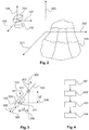
- Fig. 1 shows a level measuring device and the surface of a bulk material to be measured.
- the aim of the invention is to determine the surface of a product in order to calculate the volume or - if the density of the product is known - the weight of the product in a further step.
- cones or funnels form (when the filling material is drawn off from below in a container), which a simple level measuring device cannot accurately depict, since it only determines a simple distance value between the sensor and the bulk material.
- a filling level measuring device 100 which has a housing 101, which houses the signal generation electronics and the evaluation electronics, and an antenna unit 102, scans a cone of material, for example, line by line.
- the level measuring device itself always only determines a simple distance value 103 (d) for each sampling point or measuring point 105.
- the direction in which the distance value is to be recorded can be done by pivoting the transmitter or receiver unit 102 (e.g. an antenna in radar measuring devices).
- a purely mechanical pivoting of the antenna unit or of the entire level measuring device is described.
- the radiation direction of the antenna can be changed by digital beam forming. The procedure described below remains valid here.
- a complete scanning of the topology is achieved by rotating the sensor 100 about the x and y axes 106, 107.
- the following method advantageously uses a calculation rule that makes it possible to map the topology of the product from the pure distance values that the sensor has determined and the angles of rotation by which the sensor was rotated from its zero position.
- the following describes a calculation rule for calculating the sensor values recorded by the level measuring device in a 3D image: If the angles of rotation ( ⁇ , ⁇ , ⁇ ) of the individual axes are known (eg using an incremental encoder), the surface can be mapped using the calculation rule described below.
- the aim should be that the surface is converted into a Cartesian coordinate system in order to visualize the topology or to derive further calculations from it (e.g. volume calculation).
- the calculation rule allows the origin of the electromagnetic wave or the zero point of the distance meter or the location of the transmitting or receiving device not to have to be identical to the center of rotation.
- the reference system of the sensor in which it records the distance values changes compared to the stationary reference system.
- the fixed reference system is e.g. defined by the container or the heap.
- the suspension of the sensor has a fixed point in the fixed reference system.
- Fig. 2 is intended to clarify this fact.
- the reference numerals 201, 202 and 203 denote the x, y and z axes of the stationary reference system in which the product to be measured (here a cone of material) 104 is located.
- the sensor 100 with its mechanical rotating device 204 defines its own (body-fixed) reference system with the x, y and z axes 106, 107 and 108, which is shifted with respect to the stationary reference system during a rotation or translation by the mechanical rotating device.
- the filling level measuring device 100 here only measures a distance value to the next point in the fixed coordinate system. Has not yet been rotated, ie the Rotation angles ( ⁇ , ⁇ , ⁇ ) are all equal to zero, so the distance sensor measures by definition in the z-direction 203.
- the spatial axes of the fixed and body-fixed reference systems are then parallel. Of course, this is only one possibility of how the axes of the two systems can be defined or how the sensor was attached to the mechanical rotating device in the zero position.
- a rotation of the sensor or the sensor antenna device about the x-axis can be described with the rotation matrix Rx.
- a rotation around the y or z axis is described with the matrices Ry and Rz.
- R. x 1 0 0 0 cos ⁇ - sin ⁇ 0 sin ⁇ cos ⁇
- R. y cos ⁇ 0 sin ⁇ 0 1 0 - sin ⁇ 0 cos ⁇
- R. z cos ⁇ - sin ⁇ 0 sin ⁇ cos ⁇ 0 0 0 1
- R. cos ⁇ cos ⁇ - cos ⁇ sin ⁇ + sin ⁇ sin ⁇ sin ⁇ sin ⁇ + cos ⁇ sin ⁇ cos ⁇ cos ⁇ cos ⁇ cos ⁇ + sin ⁇ sin ⁇ sin ⁇ - sin ⁇ cos ⁇ + cos ⁇ sin ⁇ sin ⁇ - sin ⁇ sin ⁇ cos ⁇ cos ⁇ .
- R. R. 11 R. 12 R. 13th R. 21st R. 22nd R. 23 R. 31 R. 32 R. 33
- a stationary rotation of the distance sensor can now be described with the matrix R.
- the origin of the electromagnetic wave e.g. the antenna in a radar sensor
- Rotation also provides a translation, which must not be neglected.
- a possible chain of translation and rotation can be described with the following formula.
- the matrix R has been extended by one row and one column. However, R11 to R33 correspond to the original matrix R. The extension is helpful in order to be able to carry out the rotation and translation in one step and to represent the facts in compact notation.
- the translation is described by the quantities ⁇ x , ⁇ y , ⁇ z .
- ⁇ x describes a translation in the x-direction
- ⁇ y a translation in the y-direction
- ⁇ z correspondingly in the z-direction.
- the primed quantities x ', y' and z ' are the coordinates in the fixed coordinate system, which is described by the axes 201, 202 and 203.
- the unprimed values x, y and z are the coordinates in the body-fixed coordinate system (seen from the sensor).
- the angles of rotation ( ⁇ , ⁇ , ⁇ ), which were calculated in the quantities R11 to R33, and the translation ⁇ x , ⁇ y , ⁇ z show the rotation from the fixed system to the body-fixed system.
- the measuring device is as in Fig. 2 built up.
- the sensor measures a distance value d in the z-direction of the body-fixed coordinate system.
- x y z 1 0 0 - d 1
- ⁇ y, ⁇ z are equal to zero.
- angles of rotation ( ⁇ , ⁇ ) are now equal to zero.
- Fig. 3 shows a fill level measuring device 100 with an antenna unit 102 and an evaluation unit 301, which are connected to one another via a signal path 307.
- the origin of the measurement signal is located at point 304 on the antenna base. This origin can also be at a different location and is ultimately related to the calibration of the level measuring device, so it can basically be changed mathematically.
- the antenna 102 transmits a measurement signal 305 to the product surface, which is reflected by the product surface and then sent back as a measurement signal 306 to the antenna unit and received by it.
- the level measuring device 100 or at least the antenna unit 102 can be rotated about the axis 302. Another axis of rotation runs through the center of rotation 303 and runs perpendicular to the plane of the drawing and is symbolized by a circle symbol.
- the level measuring device or the antenna can also be pivoted about this axis. In this way, it is possible for the main emission axis 103 of the antenna unit 102 to scan the entire surface of the product.
- the pivot point 303 is located at a distance from the origin 304 of the measurement signal 305. This distance can be specified by the Cartesian coordinates ⁇ x 308 and ⁇ z 309.
- the y-axis is perpendicular to the plane of the drawing and ⁇ y is in the case of the Fig. 3 equal to 0.
- Fig. 4 shows a flow diagram of a method according to an embodiment of the invention.
- the measurement signal is emitted in the direction of the product surface by an antenna unit.
- the antenna unit is continuously tilted and / or digital beam shaping takes place, so that ultimately the direction of the main radiation axis of the antenna unit is changed relative to the surface of the product.
- the reflected measurement signal is recorded (over a longer period of time) and evaluated as a function of the direction of the main emission axis of the antenna unit and in the respective distance between the origin of the measurement signal and the center of rotation of the main emission axis.
- the bulk material surface topology is then determined from this data, which ultimately enables a more precise determination of the fill level / bulk material volume / bulk material mass.
Landscapes
- Physics & Mathematics (AREA)
- Engineering & Computer Science (AREA)
- Remote Sensing (AREA)
- Radar, Positioning & Navigation (AREA)
- General Physics & Mathematics (AREA)
- Electromagnetism (AREA)
- Computer Networks & Wireless Communication (AREA)
- Fluid Mechanics (AREA)
- Thermal Sciences (AREA)
- Radar Systems Or Details Thereof (AREA)
- Measurement Of Levels Of Liquids Or Fluent Solid Materials (AREA)
Claims (11)
- Appareil de mesure de niveau de remplissage pour déterminer une topologie d'une surface d'un produit de remplissage ou d'un produit en vrac, l'appareil de mesure de niveau de remplissage (100) présentant :une unité d'antenne (102) pour émettre un signal de mesure (305) en direction de la surface du produit de remplissage ou du produit en vrac dans une direction d'un axe de rayonnement principal (103) de l'unité d'antenne par rapport à la surface, laquelle direction peut être modifiée par l'appareil de mesure de niveau de remplissage de sorte qu'un balayage de la surface ait lieu, et pour recevoir le signal de mesure réfléchi à la surface du produit de remplissage ;caractérisé en ce que l'appareil de mesure de niveau de remplissage présente en outre une unité d'évaluation (301) pour déterminer la topologie de la surface du produit de remplissage ou du produit en vrac à partir du signal de mesure reçu (306) réfléchi à la surface du produit de remplissage et d'une distance d'une origine (304) du signal de mesure par rapport à un centre de rotation (303) de l'axe de rayonnement principal, l'unité d'évaluation étant conçue pour compenser le fait que l'origine (304) du signal de mesure n'est pas située au centre de rotation (303) de l'axe de rayonnement principal (103).
- Appareil de mesure de niveau de remplissage selon la revendication 1,
dans lequel la compensation est effectuée par transformation mathématique. - Appareil de mesure de niveau de remplissage selon l'une des revendications précédentes,
dans lequel l'appareil de mesure de niveau de remplissage est conçu pour faire tourner l'axe de rayonnement principal (103) autour d'un axe de rotation (302) de l'axe de rayonnement principal qui coupe le centre de rotation (303). - Appareil de mesure de niveau de remplissage selon l'une des revendications précédentes,
présentant en outre un moyen d'entrée pour permettre à un utilisateur d'entrer la distance de l'origine (304) du signal de mesure par rapport au centre de rotation (303) de l'axe de rayonnement principal (103). - Appareil de mesure de niveau de remplissage selon l'une des revendications précédentes,
dans lequel la distance du centre de rotation (303) par rapport à l'origine (304) du signal de mesure est fournie à l'unité d'évaluation (301) en coordonnées cartésiennes. - Appareil de mesure de niveau de remplissage selon l'une des revendications précédentes,
dans lequel l'appareil de mesure de niveau de remplissage est conçu pour déterminer automatiquement la distance de l'origine (304) du signal de mesure par rapport au centre de rotation (303) de l'axe de rayonnement principal lorsque la topologie de la surface du produit de remplissage ou du produit en vrac est connue. - Appareil de mesure de niveau de remplissage selon l'une des revendications précédentes,
lequel est conçu comme un radar FMCW. - Appareil de mesure de niveau de remplissage selon l'une des revendications précédentes,
lequel est conçu comme un radar de niveau de remplissage qui fonctionne selon le procédé de mesure du temps de transit d'une d'impulsion. - Procédé de mesure de niveau de remplissage qui détermine la topologie d'une surface d'un produit de remplissage ou d'un produit en vrac pour déterminer le niveau de remplissage du produit de remplissage ou du produit en vrac, le procédé présentant les étapes suivantes :émission d'un signal de mesure (305) en direction de la surface du produit de remplissage ou du produit en vrac par une unité d'antenne (102) ;modification de la direction d'un axe de rayonnement principal (103) de l'unité d'antenne par rapport à la surface de sorte qu'un balayage de la surface ait lieu ;réception du signal de mesure réfléchi à la surface du produit de remplissage ;détermination de la topologie de la surface du produit de remplissage ou du produit en vrac à partir du signal de mesure reçu, réfléchi à la surface du produit de remplissage et d'une distance d'une origine (304) du signal de mesure par rapport à un centre de rotation (303) de l'axe principal de rayonnement ;compensation du fait que l'origine (304) du signal de mesure n'est pas située au centre de rotation (303) de l'axe principal de rayonnement (103).
- Élément de programme qui, lorsqu'il est exécuté sur un processeur d'un appareil de mesure de niveau de remplissage, amène l'appareil de mesure de niveau de remplissage à exécuter les étapes suivantes :émission d'un signal de mesure (305) en direction de la surface du produit de remplissage ou du produit en vrac par une unité d'antenne (102) ;modification de la direction d'un axe de rayonnement principal (103) de l'unité d'antenne par rapport à la surface de sorte qu'un balayage de la surface ait lieu ;réception du signal de mesure réfléchi à la surface du produit de remplissage ;détermination de la topologie de la surface du produit de remplissage ou du produit en vrac à partir du signal de mesure reçu, réfléchi à la surface du produit de remplissage et d'une distance d'une origine (304) du signal de mesure par rapport à un centre de rotation (303) de l'axe principal de rayonnement ;compensation du fait que l'origine (304) du signal de mesure n'est pas située au centre de rotation (303) de l'axe principal de rayonnement (103).
- Support lisible par ordinateur sur lequel est stocké un élément de programme selon la revendication 10.
Priority Applications (1)
| Application Number | Priority Date | Filing Date | Title |
|---|---|---|---|
| HUE14720976A HUE051327T2 (hu) | 2014-05-02 | 2014-05-02 | Szintmérés felületi topológia meghatározással, forgásközép-korrekcióval |
Applications Claiming Priority (1)
| Application Number | Priority Date | Filing Date | Title |
|---|---|---|---|
| PCT/EP2014/059003 WO2015165548A1 (fr) | 2014-05-02 | 2014-05-02 | Mesure de niveau par détermination de la topologie de surface et correction du centre de rotation |
Publications (2)
| Publication Number | Publication Date |
|---|---|
| EP3137857A1 EP3137857A1 (fr) | 2017-03-08 |
| EP3137857B1 true EP3137857B1 (fr) | 2020-08-19 |
Family
ID=50630807
Family Applications (1)
| Application Number | Title | Priority Date | Filing Date |
|---|---|---|---|
| EP14720976.1A Active EP3137857B1 (fr) | 2014-05-02 | 2014-05-02 | Mesure de niveau par détermination de la topologie de surface et correction du centre de rotation |
Country Status (6)
| Country | Link |
|---|---|
| US (1) | US10254146B2 (fr) |
| EP (1) | EP3137857B1 (fr) |
| KR (1) | KR102305082B1 (fr) |
| CN (1) | CN106164627B (fr) |
| HU (1) | HUE051327T2 (fr) |
| WO (1) | WO2015165548A1 (fr) |
Cited By (2)
| Publication number | Priority date | Publication date | Assignee | Title |
|---|---|---|---|---|
| WO2024088642A1 (fr) * | 2022-10-24 | 2024-05-02 | Endress+Hauser SE+Co. KG | Transmission de valeurs de mesure de niveau de remplissage à résolution spatiale |
| WO2025131574A1 (fr) * | 2023-12-20 | 2025-06-26 | Endress+Hauser SE+Co. KG | Détermination basée sur un drone d'une hauteur de matériau en vrac |
Families Citing this family (5)
| Publication number | Priority date | Publication date | Assignee | Title |
|---|---|---|---|---|
| DE102018102366A1 (de) * | 2018-02-02 | 2019-08-08 | Endress+Hauser SE+Co. KG | Füllstandsmessgerät |
| EP4168755A1 (fr) * | 2020-06-18 | 2023-04-26 | VEGA Grieshaber KG | Radar de niveau de remplissage pour capture de niveau et de topologie |
| CN116348745A (zh) * | 2020-10-26 | 2023-06-27 | Vega格里沙贝两合公司 | 拓扑检测用填充物位测量装置 |
| KR102339939B1 (ko) * | 2021-08-05 | 2021-12-16 | 주식회사 가가 | 밀폐된 구조물 내부를 관찰할 수 있는 고분진환경용 80GHz급 저전력 1D 레벨센서 |
| KR102619507B1 (ko) * | 2021-08-05 | 2023-12-29 | 주식회사 가가 | 밀폐된 구조물 내부를 관찰할 수 있는 3d 레이더 센서 |
Family Cites Families (13)
| Publication number | Priority date | Publication date | Assignee | Title |
|---|---|---|---|---|
| US4068156A (en) | 1977-03-01 | 1978-01-10 | Martin Marietta Corporation | Rate control system for manipulator arms |
| WO2008006391A1 (fr) * | 2006-07-13 | 2008-01-17 | Siemens Aktiengesellschaft | Convertisseur de mesure de niveau selon le principe du radar et dispositif de diagnostic |
| FR2907546B1 (fr) * | 2006-10-19 | 2009-01-23 | Crealyst Sarl | Systeme de determination du relief d'une surface de remplissage de granules dans un reacteur petrochimique |
| US20080100501A1 (en) * | 2006-10-26 | 2008-05-01 | Olov Edvardsson | Antenna for a radar level gauge |
| US20080150789A1 (en) * | 2006-12-21 | 2008-06-26 | Anders Jirskog | Radar level gauge system |
| GB0705449D0 (en) * | 2007-03-22 | 2007-05-02 | Siemens Milltronics Proc Instr | A high frequency radar system |
| EP2128576B1 (fr) * | 2008-05-27 | 2016-12-28 | VEGA Grieshaber KG | Procédé de détection de double parole basé sur les propriétés acoustiques spectrales |
| KR101031079B1 (ko) * | 2008-12-26 | 2011-04-25 | 주식회사 포스코 | 고로 장입물 레벨 측정 장치 |
| US10575797B2 (en) | 2011-05-12 | 2020-03-03 | The Johns Hopkins University | Electromagnetic tracking system and methods of using same |
| DE102012003398B4 (de) * | 2012-02-23 | 2015-06-25 | Krohne Messtechnik Gmbh | Nach dem Radar-Prinzip arbeitendes Füllstandsmessgerät |
| DE102012109101A1 (de) * | 2012-09-26 | 2014-03-27 | Endress + Hauser Gmbh + Co. Kg | Füllstandsmessgerät |
| CN102983415A (zh) * | 2012-12-10 | 2013-03-20 | 西安电子工程研究所 | 一种用于物位多点测量雷达的收发天线系统 |
| EP2837950B1 (fr) * | 2013-08-14 | 2016-05-04 | VEGA Grieshaber KG | Unité de déviation de faisceau radar pour un radar de niveau de remplissage |
-
2014
- 2014-05-02 KR KR1020167030717A patent/KR102305082B1/ko active Active
- 2014-05-02 EP EP14720976.1A patent/EP3137857B1/fr active Active
- 2014-05-02 US US15/308,191 patent/US10254146B2/en active Active
- 2014-05-02 HU HUE14720976A patent/HUE051327T2/hu unknown
- 2014-05-02 WO PCT/EP2014/059003 patent/WO2015165548A1/fr not_active Ceased
- 2014-05-02 CN CN201480077959.3A patent/CN106164627B/zh active Active
Non-Patent Citations (1)
| Title |
|---|
| None * |
Cited By (2)
| Publication number | Priority date | Publication date | Assignee | Title |
|---|---|---|---|---|
| WO2024088642A1 (fr) * | 2022-10-24 | 2024-05-02 | Endress+Hauser SE+Co. KG | Transmission de valeurs de mesure de niveau de remplissage à résolution spatiale |
| WO2025131574A1 (fr) * | 2023-12-20 | 2025-06-26 | Endress+Hauser SE+Co. KG | Détermination basée sur un drone d'une hauteur de matériau en vrac |
Also Published As
| Publication number | Publication date |
|---|---|
| CN106164627B (zh) | 2019-11-19 |
| EP3137857A1 (fr) | 2017-03-08 |
| CN106164627A (zh) | 2016-11-23 |
| US10254146B2 (en) | 2019-04-09 |
| WO2015165548A1 (fr) | 2015-11-05 |
| HUE051327T2 (hu) | 2021-03-01 |
| KR102305082B1 (ko) | 2021-09-27 |
| US20170059387A1 (en) | 2017-03-02 |
| KR20160146777A (ko) | 2016-12-21 |
Similar Documents
| Publication | Publication Date | Title |
|---|---|---|
| EP3137857B1 (fr) | Mesure de niveau par détermination de la topologie de surface et correction du centre de rotation | |
| DE102005036846B4 (de) | Vorrichtung zum Messen eines Füllstands | |
| EP2803951B1 (fr) | Détermination de la topologie pour des matériaux en vrac | |
| EP0910990B1 (fr) | Appareil a rayons x | |
| DE4323511C1 (de) | Radargerät zur Hinderniswarnung | |
| EP3105939B1 (fr) | Système de mesure et procédé pour détecter des propriétés d'un objet | |
| EP3256877B1 (fr) | Dispositif de balayage laser et procédé de mesure d'un objet | |
| EP3152529B1 (fr) | Détermination de profil de défauts et de récipient | |
| DE102014008670A1 (de) | Radarkalibrierungssystem für fahrzeuge | |
| EP2128576A1 (fr) | Procédé de détection de double parole basé sur les propriétés acoustiques spectrales | |
| EP2823331A1 (fr) | Procédé et dispositif pour appréhender des objets dans l'environnement d'un véhicule | |
| EP3120121A1 (fr) | Dispositif portatif pour l'alignement d'un appareil de mesure du niveau de remplissage porté par un récipient | |
| WO2017080791A1 (fr) | Procédé d'étalonnage d'un capteur d'un véhicule automobile pour une mesure d'angle, dispositif informatique, système d'assistance à la conduite ainsi que véhicule automobile | |
| EP2803952A1 (fr) | Commande d'appareil de mesure pour la détermination de la topologie d'une surface d'un matériau en vrac | |
| EP3278067A1 (fr) | Dispositif d'antenne pour appareil de mesure de niveau de remplissage | |
| DE102004026357A1 (de) | Vorrichtung und Verfahren zum Messen eines Objektes | |
| EP2848902B1 (fr) | Procédé de détermination d'un niveau de remplissage d'un milieu et dispositif de détermination d'un niveau de remplissage d'un milieu | |
| WO2022111942A1 (fr) | Mesure de volume de remplissage | |
| EP4214478B1 (fr) | Appareil de mesure de niveau à résolution d'angle | |
| DE102018104056B3 (de) | Verfahren zur optimierten Anordnung und Ausrichtung eines Feldgerätes | |
| DE102021103543A1 (de) | Winkelauflösendes Füllstandsmessgerät | |
| DE102021206401A1 (de) | Computertomographieanordnung und Verfahren zum Betreiben einer Computertomographieanordnung | |
| EP2150172A1 (fr) | Procédé et dispositif destinés à corriger une mesure de pression sanguine | |
| DE102018112819A1 (de) | Winkelauflösendes Entfernungsmessgerät | |
| DE102022115284A1 (de) | Prüfvorrichtung zum Test eines mit elektromagnetischen Wellen arbeitenden Abstandssensors und Verfahren zur Überprüfung eines Abstandssensor-Prüfstandes mit einem gefalteten Strahlengang |
Legal Events
| Date | Code | Title | Description |
|---|---|---|---|
| STAA | Information on the status of an ep patent application or granted ep patent |
Free format text: STATUS: THE INTERNATIONAL PUBLICATION HAS BEEN MADE |
|
| PUAI | Public reference made under article 153(3) epc to a published international application that has entered the european phase |
Free format text: ORIGINAL CODE: 0009012 |
|
| STAA | Information on the status of an ep patent application or granted ep patent |
Free format text: STATUS: REQUEST FOR EXAMINATION WAS MADE |
|
| 17P | Request for examination filed |
Effective date: 20161117 |
|
| AK | Designated contracting states |
Kind code of ref document: A1 Designated state(s): AL AT BE BG CH CY CZ DE DK EE ES FI FR GB GR HR HU IE IS IT LI LT LU LV MC MK MT NL NO PL PT RO RS SE SI SK SM TR |
|
| AX | Request for extension of the european patent |
Extension state: BA ME |
|
| DAX | Request for extension of the european patent (deleted) | ||
| GRAP | Despatch of communication of intention to grant a patent |
Free format text: ORIGINAL CODE: EPIDOSNIGR1 |
|
| STAA | Information on the status of an ep patent application or granted ep patent |
Free format text: STATUS: GRANT OF PATENT IS INTENDED |
|
| RIC1 | Information provided on ipc code assigned before grant |
Ipc: G01S 13/89 20060101ALI20200420BHEP Ipc: G01F 23/284 20060101AFI20200420BHEP Ipc: G01F 22/00 20060101ALI20200420BHEP Ipc: G01S 13/88 20060101ALI20200420BHEP |
|
| INTG | Intention to grant announced |
Effective date: 20200508 |
|
| GRAS | Grant fee paid |
Free format text: ORIGINAL CODE: EPIDOSNIGR3 |
|
| GRAA | (expected) grant |
Free format text: ORIGINAL CODE: 0009210 |
|
| STAA | Information on the status of an ep patent application or granted ep patent |
Free format text: STATUS: THE PATENT HAS BEEN GRANTED |
|
| AK | Designated contracting states |
Kind code of ref document: B1 Designated state(s): AL AT BE BG CH CY CZ DE DK EE ES FI FR GB GR HR HU IE IS IT LI LT LU LV MC MK MT NL NO PL PT RO RS SE SI SK SM TR |
|
| REG | Reference to a national code |
Ref country code: CH Ref legal event code: EP |
|
| REG | Reference to a national code |
Ref country code: DE Ref legal event code: R096 Ref document number: 502014014644 Country of ref document: DE |
|
| REG | Reference to a national code |
Ref country code: AT Ref legal event code: REF Ref document number: 1304460 Country of ref document: AT Kind code of ref document: T Effective date: 20200915 |
|
| REG | Reference to a national code |
Ref country code: IE Ref legal event code: FG4D Free format text: LANGUAGE OF EP DOCUMENT: GERMAN |
|
| REG | Reference to a national code |
Ref country code: SE Ref legal event code: TRGR |
|
| REG | Reference to a national code |
Ref country code: LT Ref legal event code: MG4D |
|
| REG | Reference to a national code |
Ref country code: NL Ref legal event code: MP Effective date: 20200819 |
|
| PG25 | Lapsed in a contracting state [announced via postgrant information from national office to epo] |
Ref country code: NO Free format text: LAPSE BECAUSE OF FAILURE TO SUBMIT A TRANSLATION OF THE DESCRIPTION OR TO PAY THE FEE WITHIN THE PRESCRIBED TIME-LIMIT Effective date: 20201119 Ref country code: HR Free format text: LAPSE BECAUSE OF FAILURE TO SUBMIT A TRANSLATION OF THE DESCRIPTION OR TO PAY THE FEE WITHIN THE PRESCRIBED TIME-LIMIT Effective date: 20200819 Ref country code: FI Free format text: LAPSE BECAUSE OF FAILURE TO SUBMIT A TRANSLATION OF THE DESCRIPTION OR TO PAY THE FEE WITHIN THE PRESCRIBED TIME-LIMIT Effective date: 20200819 Ref country code: GR Free format text: LAPSE BECAUSE OF FAILURE TO SUBMIT A TRANSLATION OF THE DESCRIPTION OR TO PAY THE FEE WITHIN THE PRESCRIBED TIME-LIMIT Effective date: 20201120 Ref country code: PT Free format text: LAPSE BECAUSE OF FAILURE TO SUBMIT A TRANSLATION OF THE DESCRIPTION OR TO PAY THE FEE WITHIN THE PRESCRIBED TIME-LIMIT Effective date: 20201221 Ref country code: LT Free format text: LAPSE BECAUSE OF FAILURE TO SUBMIT A TRANSLATION OF THE DESCRIPTION OR TO PAY THE FEE WITHIN THE PRESCRIBED TIME-LIMIT Effective date: 20200819 Ref country code: BG Free format text: LAPSE BECAUSE OF FAILURE TO SUBMIT A TRANSLATION OF THE DESCRIPTION OR TO PAY THE FEE WITHIN THE PRESCRIBED TIME-LIMIT Effective date: 20201119 |
|
| PG25 | Lapsed in a contracting state [announced via postgrant information from national office to epo] |
Ref country code: LV Free format text: LAPSE BECAUSE OF FAILURE TO SUBMIT A TRANSLATION OF THE DESCRIPTION OR TO PAY THE FEE WITHIN THE PRESCRIBED TIME-LIMIT Effective date: 20200819 Ref country code: NL Free format text: LAPSE BECAUSE OF FAILURE TO SUBMIT A TRANSLATION OF THE DESCRIPTION OR TO PAY THE FEE WITHIN THE PRESCRIBED TIME-LIMIT Effective date: 20200819 Ref country code: PL Free format text: LAPSE BECAUSE OF FAILURE TO SUBMIT A TRANSLATION OF THE DESCRIPTION OR TO PAY THE FEE WITHIN THE PRESCRIBED TIME-LIMIT Effective date: 20200819 Ref country code: RS Free format text: LAPSE BECAUSE OF FAILURE TO SUBMIT A TRANSLATION OF THE DESCRIPTION OR TO PAY THE FEE WITHIN THE PRESCRIBED TIME-LIMIT Effective date: 20200819 Ref country code: IS Free format text: LAPSE BECAUSE OF FAILURE TO SUBMIT A TRANSLATION OF THE DESCRIPTION OR TO PAY THE FEE WITHIN THE PRESCRIBED TIME-LIMIT Effective date: 20201219 |
|
| REG | Reference to a national code |
Ref country code: HU Ref legal event code: AG4A Ref document number: E051327 Country of ref document: HU |
|
| PG25 | Lapsed in a contracting state [announced via postgrant information from national office to epo] |
Ref country code: DK Free format text: LAPSE BECAUSE OF FAILURE TO SUBMIT A TRANSLATION OF THE DESCRIPTION OR TO PAY THE FEE WITHIN THE PRESCRIBED TIME-LIMIT Effective date: 20200819 Ref country code: CZ Free format text: LAPSE BECAUSE OF FAILURE TO SUBMIT A TRANSLATION OF THE DESCRIPTION OR TO PAY THE FEE WITHIN THE PRESCRIBED TIME-LIMIT Effective date: 20200819 Ref country code: EE Free format text: LAPSE BECAUSE OF FAILURE TO SUBMIT A TRANSLATION OF THE DESCRIPTION OR TO PAY THE FEE WITHIN THE PRESCRIBED TIME-LIMIT Effective date: 20200819 Ref country code: RO Free format text: LAPSE BECAUSE OF FAILURE TO SUBMIT A TRANSLATION OF THE DESCRIPTION OR TO PAY THE FEE WITHIN THE PRESCRIBED TIME-LIMIT Effective date: 20200819 Ref country code: SM Free format text: LAPSE BECAUSE OF FAILURE TO SUBMIT A TRANSLATION OF THE DESCRIPTION OR TO PAY THE FEE WITHIN THE PRESCRIBED TIME-LIMIT Effective date: 20200819 |
|
| REG | Reference to a national code |
Ref country code: DE Ref legal event code: R097 Ref document number: 502014014644 Country of ref document: DE |
|
| PG25 | Lapsed in a contracting state [announced via postgrant information from national office to epo] |
Ref country code: AL Free format text: LAPSE BECAUSE OF FAILURE TO SUBMIT A TRANSLATION OF THE DESCRIPTION OR TO PAY THE FEE WITHIN THE PRESCRIBED TIME-LIMIT Effective date: 20200819 Ref country code: ES Free format text: LAPSE BECAUSE OF FAILURE TO SUBMIT A TRANSLATION OF THE DESCRIPTION OR TO PAY THE FEE WITHIN THE PRESCRIBED TIME-LIMIT Effective date: 20200819 |
|
| PLBE | No opposition filed within time limit |
Free format text: ORIGINAL CODE: 0009261 |
|
| STAA | Information on the status of an ep patent application or granted ep patent |
Free format text: STATUS: NO OPPOSITION FILED WITHIN TIME LIMIT |
|
| PG25 | Lapsed in a contracting state [announced via postgrant information from national office to epo] |
Ref country code: SK Free format text: LAPSE BECAUSE OF FAILURE TO SUBMIT A TRANSLATION OF THE DESCRIPTION OR TO PAY THE FEE WITHIN THE PRESCRIBED TIME-LIMIT Effective date: 20200819 |
|
| 26N | No opposition filed |
Effective date: 20210520 |
|
| PG25 | Lapsed in a contracting state [announced via postgrant information from national office to epo] |
Ref country code: IT Free format text: LAPSE BECAUSE OF FAILURE TO SUBMIT A TRANSLATION OF THE DESCRIPTION OR TO PAY THE FEE WITHIN THE PRESCRIBED TIME-LIMIT Effective date: 20200819 |
|
| PG25 | Lapsed in a contracting state [announced via postgrant information from national office to epo] |
Ref country code: SI Free format text: LAPSE BECAUSE OF FAILURE TO SUBMIT A TRANSLATION OF THE DESCRIPTION OR TO PAY THE FEE WITHIN THE PRESCRIBED TIME-LIMIT Effective date: 20200819 |
|
| REG | Reference to a national code |
Ref country code: CH Ref legal event code: PL |
|
| PG25 | Lapsed in a contracting state [announced via postgrant information from national office to epo] |
Ref country code: MC Free format text: LAPSE BECAUSE OF FAILURE TO SUBMIT A TRANSLATION OF THE DESCRIPTION OR TO PAY THE FEE WITHIN THE PRESCRIBED TIME-LIMIT Effective date: 20200819 Ref country code: LU Free format text: LAPSE BECAUSE OF NON-PAYMENT OF DUE FEES Effective date: 20210502 Ref country code: LI Free format text: LAPSE BECAUSE OF NON-PAYMENT OF DUE FEES Effective date: 20210531 Ref country code: CH Free format text: LAPSE BECAUSE OF NON-PAYMENT OF DUE FEES Effective date: 20210531 |
|
| REG | Reference to a national code |
Ref country code: BE Ref legal event code: MM Effective date: 20210531 |
|
| PG25 | Lapsed in a contracting state [announced via postgrant information from national office to epo] |
Ref country code: IE Free format text: LAPSE BECAUSE OF NON-PAYMENT OF DUE FEES Effective date: 20210502 |
|
| REG | Reference to a national code |
Ref country code: AT Ref legal event code: MM01 Ref document number: 1304460 Country of ref document: AT Kind code of ref document: T Effective date: 20210502 |
|
| PG25 | Lapsed in a contracting state [announced via postgrant information from national office to epo] |
Ref country code: BE Free format text: LAPSE BECAUSE OF NON-PAYMENT OF DUE FEES Effective date: 20210531 |
|
| PG25 | Lapsed in a contracting state [announced via postgrant information from national office to epo] |
Ref country code: AT Free format text: LAPSE BECAUSE OF NON-PAYMENT OF DUE FEES Effective date: 20210502 |
|
| P01 | Opt-out of the competence of the unified patent court (upc) registered |
Effective date: 20230508 |
|
| PG25 | Lapsed in a contracting state [announced via postgrant information from national office to epo] |
Ref country code: CY Free format text: LAPSE BECAUSE OF FAILURE TO SUBMIT A TRANSLATION OF THE DESCRIPTION OR TO PAY THE FEE WITHIN THE PRESCRIBED TIME-LIMIT Effective date: 20200819 |
|
| PG25 | Lapsed in a contracting state [announced via postgrant information from national office to epo] |
Ref country code: MK Free format text: LAPSE BECAUSE OF FAILURE TO SUBMIT A TRANSLATION OF THE DESCRIPTION OR TO PAY THE FEE WITHIN THE PRESCRIBED TIME-LIMIT Effective date: 20200819 |
|
| PG25 | Lapsed in a contracting state [announced via postgrant information from national office to epo] |
Ref country code: MT Free format text: LAPSE BECAUSE OF FAILURE TO SUBMIT A TRANSLATION OF THE DESCRIPTION OR TO PAY THE FEE WITHIN THE PRESCRIBED TIME-LIMIT Effective date: 20200819 |
|
| PGFP | Annual fee paid to national office [announced via postgrant information from national office to epo] |
Ref country code: DE Payment date: 20250519 Year of fee payment: 12 |
|
| PGFP | Annual fee paid to national office [announced via postgrant information from national office to epo] |
Ref country code: GB Payment date: 20250522 Year of fee payment: 12 |
|
| PGFP | Annual fee paid to national office [announced via postgrant information from national office to epo] |
Ref country code: HU Payment date: 20250430 Year of fee payment: 12 |
|
| PGFP | Annual fee paid to national office [announced via postgrant information from national office to epo] |
Ref country code: FR Payment date: 20250523 Year of fee payment: 12 |
|
| PGFP | Annual fee paid to national office [announced via postgrant information from national office to epo] |
Ref country code: SE Payment date: 20250522 Year of fee payment: 12 |
|
| PG25 | Lapsed in a contracting state [announced via postgrant information from national office to epo] |
Ref country code: TR Free format text: LAPSE BECAUSE OF FAILURE TO SUBMIT A TRANSLATION OF THE DESCRIPTION OR TO PAY THE FEE WITHIN THE PRESCRIBED TIME-LIMIT Effective date: 20200819 |