EP3137948B1 - Dispositif et procédé de surveillance d'une partie de machine mobile avec protection contre les erreurs - Google Patents
Dispositif et procédé de surveillance d'une partie de machine mobile avec protection contre les erreurs Download PDFInfo
- Publication number
- EP3137948B1 EP3137948B1 EP15723163.0A EP15723163A EP3137948B1 EP 3137948 B1 EP3137948 B1 EP 3137948B1 EP 15723163 A EP15723163 A EP 15723163A EP 3137948 B1 EP3137948 B1 EP 3137948B1
- Authority
- EP
- European Patent Office
- Prior art keywords
- fail
- machine part
- safe
- evaluation unit
- moving machine
- Prior art date
- Legal status (The legal status is an assumption and is not a legal conclusion. Google has not performed a legal analysis and makes no representation as to the accuracy of the status listed.)
- Active
Links
Images

Classifications
-
- G—PHYSICS
- G05—CONTROLLING; REGULATING
- G05B—CONTROL OR REGULATING SYSTEMS IN GENERAL; FUNCTIONAL ELEMENTS OF SUCH SYSTEMS; MONITORING OR TESTING ARRANGEMENTS FOR SUCH SYSTEMS OR ELEMENTS
- G05B9/00—Safety arrangements
- G05B9/02—Safety arrangements electric
-
- G—PHYSICS
- G05—CONTROLLING; REGULATING
- G05B—CONTROL OR REGULATING SYSTEMS IN GENERAL; FUNCTIONAL ELEMENTS OF SUCH SYSTEMS; MONITORING OR TESTING ARRANGEMENTS FOR SUCH SYSTEMS OR ELEMENTS
- G05B19/00—Program-control systems
- G05B19/02—Program-control systems electric
- G05B19/18—Numerical control [NC], i.e. automatically operating machines, in particular machine tools, e.g. in a manufacturing environment, so as to execute positioning, movement or co-ordinated operations by means of program data in numerical form
- G05B19/406—Numerical control [NC], i.e. automatically operating machines, in particular machine tools, e.g. in a manufacturing environment, so as to execute positioning, movement or co-ordinated operations by means of program data in numerical form characterised by monitoring or safety
-
- G—PHYSICS
- G05—CONTROLLING; REGULATING
- G05B—CONTROL OR REGULATING SYSTEMS IN GENERAL; FUNCTIONAL ELEMENTS OF SUCH SYSTEMS; MONITORING OR TESTING ARRANGEMENTS FOR SUCH SYSTEMS OR ELEMENTS
- G05B23/00—Testing or monitoring of control systems or parts thereof
- G05B23/02—Electric testing or monitoring
- G05B23/0205—Electric testing or monitoring by means of a monitoring system capable of detecting and responding to faults
- G05B23/0259—Electric testing or monitoring by means of a monitoring system capable of detecting and responding to faults characterized by the response to fault detection
- G05B23/0286—Modifications to the monitored process, e.g. stopping operation or adapting control
- G05B23/0291—Switching into safety or degraded mode, e.g. protection and supervision after failure
-
- H—ELECTRICITY
- H02—GENERATION; CONVERSION OR DISTRIBUTION OF ELECTRIC POWER
- H02H—EMERGENCY PROTECTIVE CIRCUIT ARRANGEMENTS
- H02H7/00—Emergency protective circuit arrangements specially adapted for specific types of electric machines or apparatus or for sectionalised protection of cable or line systems, and effecting automatic switching in the event of an undesired change from normal working conditions
- H02H7/08—Emergency protective circuit arrangements specially adapted for specific types of electric machines or apparatus or for sectionalised protection of cable or line systems, and effecting automatic switching in the event of an undesired change from normal working conditions for dynamo-electric motors
- H02H7/0833—Emergency protective circuit arrangements specially adapted for specific types of electric machines or apparatus or for sectionalised protection of cable or line systems, and effecting automatic switching in the event of an undesired change from normal working conditions for dynamo-electric motors for electric motors with control arrangements
- H02H7/0844—Fail safe control, e.g. by comparing control signal and controlled current, isolating motor on commutation error
-
- G—PHYSICS
- G05—CONTROLLING; REGULATING
- G05B—CONTROL OR REGULATING SYSTEMS IN GENERAL; FUNCTIONAL ELEMENTS OF SUCH SYSTEMS; MONITORING OR TESTING ARRANGEMENTS FOR SUCH SYSTEMS OR ELEMENTS
- G05B2219/00—Program-control systems
- G05B2219/20—Pc systems
- G05B2219/24—Pc safety
- G05B2219/24008—Safety integrity level, safety integrated systems SIL SIS
-
- G—PHYSICS
- G05—CONTROLLING; REGULATING
- G05B—CONTROL OR REGULATING SYSTEMS IN GENERAL; FUNCTIONAL ELEMENTS OF SUCH SYSTEMS; MONITORING OR TESTING ARRANGEMENTS FOR SUCH SYSTEMS OR ELEMENTS
- G05B2219/00—Program-control systems
- G05B2219/20—Pc systems
- G05B2219/24—Pc safety
- G05B2219/24182—Redundancy
-
- G—PHYSICS
- G05—CONTROLLING; REGULATING
- G05B—CONTROL OR REGULATING SYSTEMS IN GENERAL; FUNCTIONAL ELEMENTS OF SUCH SYSTEMS; MONITORING OR TESTING ARRANGEMENTS FOR SUCH SYSTEMS OR ELEMENTS
- G05B2219/00—Program-control systems
- G05B2219/30—Nc systems
- G05B2219/50—Machine tool, machine tool null till machine tool work handling
- G05B2219/50177—Protection for operator during operation, machining
-
- G—PHYSICS
- G05—CONTROLLING; REGULATING
- G05B—CONTROL OR REGULATING SYSTEMS IN GENERAL; FUNCTIONAL ELEMENTS OF SUCH SYSTEMS; MONITORING OR TESTING ARRANGEMENTS FOR SUCH SYSTEMS OR ELEMENTS
- G05B2219/00—Program-control systems
- G05B2219/30—Nc systems
- G05B2219/50—Machine tool, machine tool null till machine tool work handling
- G05B2219/50198—Emergency stop
-
- Y—GENERAL TAGGING OF NEW TECHNOLOGICAL DEVELOPMENTS; GENERAL TAGGING OF CROSS-SECTIONAL TECHNOLOGIES SPANNING OVER SEVERAL SECTIONS OF THE IPC; TECHNICAL SUBJECTS COVERED BY FORMER USPC CROSS-REFERENCE ART COLLECTIONS [XRACs] AND DIGESTS
- Y02—TECHNOLOGIES OR APPLICATIONS FOR MITIGATION OR ADAPTATION AGAINST CLIMATE CHANGE
- Y02P—CLIMATE CHANGE MITIGATION TECHNOLOGIES IN THE PRODUCTION OR PROCESSING OF GOODS
- Y02P90/00—Enabling technologies with a potential contribution to greenhouse gas [GHG] emissions mitigation
- Y02P90/02—Total factory control, e.g. smart factories, flexible manufacturing systems [FMS] or integrated manufacturing systems [IMS]
Definitions
- the present invention relates to a device for failsafe monitoring of a number of runs of a movable machine part through a defined range of motion with a failsafe evaluation unit for providing a failsafe switch-off signal.
- the present invention relates to a method for failsafe monitoring of a number of runs of a movable machine part through a defined range of motion.
- the present invention relates in particular to the field of machine and plant safety.
- the operation of modern machines and systems is integrated into a comprehensive safety concept, regardless of whether it is machine tools such as machining centers, presses, assembly systems or robots.
- machine tools such as machining centers, presses, assembly systems or robots.
- many machines and systems pose a risk to people, goods and processes, which are hardly recognizable at first sight. Therefore, there are a number of guidelines, standards and laws that prescribe certain safety precautions that must be taken into account when implementing technical systems.
- the present invention relates in particular to devices that have a safety integrity level (SIL) classification of at least SIL-2 in terms of functional safety or achieve a performance level greater than PL c , with the performance level according to EN ISO 13849-1 the probability of a dangerous failure describes per hour.
- SIL safety integrity level
- EP 1 736 842 A1 discloses, by way of example, a machine controller for controlling a hazardous machine, such as a press, for example, which enables rapid shutdown by using logic that is independent of a cycle time of the machine controller for time-critical control commands.
- the monitoring of a technical system that has moving machine parts that can pose a risk therefore regularly requires two monitoring devices that are often separate from one another.
- an area is secured to restrict access by people or to prevent passage or To monitor pass-through areas, with walls, stable protective grilles or electro-mechanical or opto-electronic protective devices being used regularly.
- a moving machine part itself must be monitored to ensure that it is within its operating range. This is usually done with position switches, light grids or camera-based protective devices, with which the limits of the effective area are checked in order to register an exit from the effective area.
- the respective position of the moving machine part can also be determined directly in a safety-relevant manner.
- this object is achieved by an apparatus according to claim 1.
- this object is further achieved by a method according to claim 12.
- the new device and the new method are therefore based on the idea of monitoring a range of movement of a movable machine part using position monitoring of the movable machine part and, at least in the event that the movable machine part leaves its defined, permissible effective range, a fail-safe, preferably redundant To generate a shutdown signal with which a technical system can be safely shut down if necessary.
- the new device and the new method manages without or with a reduced number of additional sensors in order to completely monitor the limits of a movement area in a safety-relevant manner. This simplifies the monitoring of a movement area and saves costs for additional sensors, actuators and their wiring.
- the new device and the new method make it possible to flexibly select the movement areas to be monitored. Therefore, the areas do not have to be determined by physical boundaries, but can be absolute or relative position of the moving machine part. For example, a range of movement and its limits can be defined by a relative position specification in relation to a fixed point of rest. Thus, the new device can be quickly and flexibly adapted to specific circumstances without having to make any structural changes or changes to the sensor arrangements.
- the flexible selection of the range of motion also has the advantage that a multiple passage of the movable machine part through a physical range of motion can be taken into account, for example by defining a range of motion that goes beyond the physical range of motion.
- the range of movement can thus be determined by a specific number of revolutions.
- the speed would be the corresponding Drive the relevant movement variable from which the number of revolutions can be determined directly or from a transmission ratio of the drive.
- the encoder signal can originate, for example, from a safe rotary encoder, so that the encoder signal itself is fail-safe.
- redundant detection of the movement variable at the input of the device according to the invention is also possible.
- the movement can be detected independently of the direction of movement or rotation.
- the movement can be a rotary or a translatory movement.
- the above procedure can therefore also be used for lateral movements.
- the physical relationship between acceleration, speed and distance covered is well known.
- the speed of a moving system part can be calculated from the measured acceleration by integrating the recorded acceleration values over time. Equally, the distance covered can be determined by integration over the speed.
- the speed and the position of the moving plant part at the beginning of the integration time must be known. However, this is not a problem in an automated, stationary system, since as a rule, at least after the system is switched on, there is a defined idle state or it is assumed in an initialization process.
- various transmitter signals which represent a movement variable
- various transmitter signals are advantageously already available in many technical systems with moving machine parts and can be reused by the new device.
- existing sensors can be used to provide the encoder signal, which means that area monitoring can be implemented even more cheaply.
- the aspect of reuse can also come into play with regard to the security concept, in that the new device can advantageously be combined with other sensors, for example sensors for area protection, or, in the opposite case, replaces them.
- the new device has the advantage that it is largely independent of the respective system type and the safety concept used and can therefore be used for a large number of different systems.
- the present invention thus offers a cost-effective and flexible option for safety-related monitoring of a movement area of a movable machine part. The above object is therefore completely solved.
- the fail-safe evaluation unit is also designed to use the movement variable to determine a first and a second direction of movement of the movable machine part in a safety-relevant manner.
- a direction of movement of the movable machine part is also determined in a safety-relevant manner.
- This has the advantage that the defined range of movement can also be defined as a function of the relative position of the machine part and the direction of movement.
- safety-relevant means that an erroneous determination of the direction of movement is mastered, i.e. the device is designed in such a way that the fail-safe switch-off signal is provided despite an erroneous detection of the direction of movement.
- the direction of movement can in particular be a direction of rotation.
- the device also has a counter in which the number of passes can be stored, the counter being increased by a first defined amount when the movable machine part has completely passed through the defined range of motion in a first direction of motion and by a second defined amount is reduced when the movable machine part has completely passed through the defined range of motion in a second direction of motion.
- the range of motion is defined by a first and a second limit, with each pass through the range of motion in a specified direction increasing the counter and decreasing the counter by a specific amount in the opposite direction.
- the counter thus provides information about the relative position within the movement range. In this way, a zero point can be established, for example the resting position of the moving machine part, with the counter indicating the absolute value of the deviation from this resting point and the sign indicating the respective direction.
- Rotary movements can be monitored particularly easily via the counter, whereby the defined range of movement can also include multiple revolutions and takes forward and reverse movement into account.
- the device has a memory in which at least one value that represents a limit of the defined range of motion can be stored.
- the limits can advantageously be changed manually by the user.
- the device can be adapted particularly flexibly to the respective circumstances.
- the parameters for the limits of the movement area have to be changed in memory.
- movement areas that are not physically limited can also be defined and monitored in this way.
- the limits can be represented by different values, for example by absolute and/or relative position information or by angles of rotation in the case of a circular movement.
- the limits of the range of motion are specified in relation to a rest position of the movable machine part, with a variable value for the rest position also being able to be stored in the memory.
- the evaluation unit is designed to provide an output signal which represents the first or second direction of movement.
- an additional output signal can be provided which provides error-proof information about the respective direction of movement.
- Such a signal can advantageously be evaluated by a higher-level controller and integrated into the overall safety concept. In this way, other protective devices can be supplemented and/or replaced if necessary.
- the evaluation unit is designed to provide a warning signal if the number of times the movable machine part passes through the defined range of motion exceeds a defined value.
- the new device can also provide a warning signal when a specific number of runs has taken place.
- a warning signal can be picked up by a controller, for example, in order to take corrective action before the device provides the switch-off signal in order to switch off the system. In this way, unnecessary downtimes caused by avoidable shutdown processes can be avoided.
- the evaluation unit provides the switch-off signal when a first defined value of the movement variable is exceeded.
- the size of the motion itself can also be monitored.
- the device according to the invention can thus advantageously also be used for fail-safe speed monitoring and, if necessary, completely or partially replace an additional sensor system.
- the evaluation unit is designed to provide an enable signal if the movement variable falls below a second defined value or represents a standstill.
- the device according to the invention can provide a further signal, as a function of which, for example, access to a system can be controlled. Particularly in the case of trailing machines that continue to move even after the supply voltage has been switched off, access to the machine can be restricted using the release signal until the machine to be monitored no longer poses a risk. In this way, further safety measures can be taken over by the device according to the invention.
- the device has a fail-safe signal transmitter for providing the transmitter signal with a first and a second measurement channel.
- connection of a fail-safe, preferably redundant, evaluation unit with a fail-safe signal transmitter enables complete and redundant monitoring without additional components. Such a combination is therefore particularly advantageous and economical compared to methods in which separate units are required to record the redundant input variables.
- the fail-safe signal generator is particularly preferably a rotary encoder with an optical and a magnetic scanning unit on a drive shaft.
- An optical and a magnetic scanning unit make it particularly advantageous to form two full measurement channels that work independently of one another.
- the safety criterion of diversity can also be implemented by the two measurement channels.
- Both measuring systems preferably have a synchronous serial interface (SSI) which can transfer the same data format. In this way, the evaluation unit can evaluate both channels uniformly.
- SSI synchronous serial interface
- rotary encoders can also be used that only have optical or only magnetic scanning units.
- the device has a first and a second switching element, the switch-off signal being provided as a function of the switch position of the first and second switching element.
- a redundant and thus fail-safe switch-off signal can be generated particularly well and consistent redundancy from the sensor inputs to the actuators can be guaranteed.
- an operating voltage is passed via the switching elements, the absence of which at the outputs leads directly or indirectly to a system to be monitored being switched off.
- the fail-safe evaluation unit is designed with two-channel redundancy.
- a fail-safe evaluation unit can be guaranteed particularly well with a two-channel, redundant evaluation unit.
- a two-channel evaluation unit it can be ensured that a system to be monitored can still be switched off even if one channel fails.
- the evaluation unit has a first and a second processing unit which each generate an output signal which represents the switch-off signal, the first and the second processing unit being designed to monitor one another.
- a redundant and therefore fail-safe evaluation unit can be implemented particularly easily and reliably by this configuration.
- Mutual monitoring not only ensures that the system is shut down safely in the event of a fault in one channel, but that a faulty channel can also be reliably detected.
- Monitoring preferably also includes periodic testing of the individual channels by the evaluation unit and/or a higher-level controller.
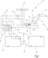
- a preferred exemplary embodiment of the new device is denoted in its entirety by the reference number 10 .
- the device is used here to monitor a technical installation 12 which is indicated by a robot 14 .
- the robot 14 is arranged here on a fixed base 16 on which a movable machine part 18 is placed, which can rotate completely about its longitudinal axis 20 here.
- a robot arm 22 is arranged on the movable machine part 18 and can be moved in space by the rotary movement of the movable machine part 18 .
- the area of action of the technical system to be secured results here from the area of action of the robot arm 22 plus the area claimed by a moving load.
- the robot 14 is driven here by an electric drive 24 which is coupled to the movable machine part 18 via a shaft 26 .
- the shaft 26 is coupled to the movable machine part, for example, via a transmission (not shown here) with a fixed ratio, so that the movement of the movable machine part 18 is proportional to a speed 28 of the electric drive 24 .
- the speed 28 of the drive is detected here by a signal transmitter and transmitted to the device 10 via the line 30 as a transmission signal.
- Various ways of detecting the speed 28 are possible, but preferably a safe rotary encoder, not shown here, is used, the sensors of which are coupled to the shaft 26 and which is designed to determine the speed of the shaft 26 in a safety-relevant manner and to generate a corresponding encoder signal .
- the speed 28 represents only one possibility for a movement variable.
- the acceleration of the shaft or an absolute distance can also be recorded by appropriate sensors.
- the device is therefore not limited to a specific movement quantity, but rather can preferably use different movement quantities for the evaluation, for example to check the plausibility of an evaluation result using different individual measurements.
- the line 30 is also connected to an input 32 of the device 10, via which the encoder signal is forwarded to the fail-safe evaluation unit 34.
- the fail-safe design of the evaluation unit 34 is indicated here by two separate processing units 36, 38 which preferably mutually can monitor.
- the device 10 is thus designed with two channels of redundancy.
- the fail-safe evaluation unit 34 uses the movement variable or variables transmitted with the encoder signal to determine the respective runs through a defined range of movement of the robot 14.
- the range of movement is defined here by a complete revolution of the movable machine part 18, where the robot 14 can run through this movement range several times, ie the robot can rotate around its own axis 20 several times.
- the defined range of movement is not limited to circular movements, but can also include lateral movements.
- the failsafe evaluation unit 34 uses the rotational speed 28 of the electric drive 24 to determine the actual number of rotations of the movable machine part 18 about its own axis 20.
- the movement of the movable machine part 18 is alternative or supplementary determined by other motion quantities.
- the movement variable does not have to be recorded directly at the drive 24, but can also be determined, for example, by acceleration sensors on the movable machine part 18 itself.
- Different movement variables are particularly preferably recorded and evaluated in order to enable diverse monitoring.
- the movement can preferably also be detected relative to a defined fixed point, for example a resting position of the robot 14. In this way, the evaluation can be based on relative values, which means that variables from different sensors can be compared and/or combined more easily.
- the fail-safe evaluation unit 34 provides a fail-safe switch-off signal if a number of runs through the defined movement range exceeds a defined threshold value.
- the threshold value can also assume the value 1, so that the fail-safe switch-off signal is generated after the defined movement range has been passed through once.
- fail-safe means that the shutdown signal can always be used to ensure that a system to be monitored shuts down, even if parts of the safety function become inoperable. Preference is thus a redundant switch-off signal is also used in this case, as indicated here by the two switching elements 40, 42.
- a supply voltage is fed to the outputs 44, 46, with which the contactors 50 are operated via the lines 48 in this exemplary embodiment.
- the contacts of the contactors 50 are in turn in series in a manner known per se in a power supply 52 of the electric drive 24.
- the electric drive 24 is supplied and ready for operation only when the contactors are energized and thus attracted. It follows that at least one of the contactors 50 drops out when one of the switching elements 40, 42 is opened, as a result of which the operation of the robot 14 is safely stopped due to the interrupted power supply 52.
- a threshold value could be given by a physical limitation of the possibility of movement of the movable machine part, which does not result directly from the type of drive.
- a compressed air line 54 between the base 16 and the robot arm 22 is indicated here, for example, which can only wrap a certain number of revolutions around the robot.
- the device according to the invention enables the robot 14 to be switched off safely as soon as the defined number of revolutions has taken place.
- the monitoring is not limited to the exemplary embodiment shown, but is used for any monitoring of a number of runs through a movement area, in which a movement variable can be used to determine the absolute or relative position.
- the exemplary embodiment shown in FIG. 1 can, in addition to monitoring the number of passages through a defined range of movement, also carry out other safety measures in whole or in part.
- a protective fence 56 with a monitored door 58 is provided here to protect against unauthorized access to the working area of the robot 14 .
- the door 58 has a safety switch 60 with a sensor 62 and an actuator 64, the safety switch 60 only generates a release signal 66 when the door 58 properly closed is.
- the release signal 66 of the safety switch 60 is received at the input 34 of the device 10 according to the invention and preferably processed as a binary signal by the evaluation unit 34, which, depending on the release signal 66, controls the outputs 44, 46 in the manner described above.
- the device 10 can instruct the safety door switch 44 to lock the safety door until a corresponding safe state of the technical system 12 is reached. This can be reached, for example, when the drive is at a standstill or the speed has fallen below a defined value.
- the safety switch 60 can also have a tumbler, so that the door can only be opened when a corresponding release signal from the device 10 is present.
- the device according to the invention can therefore in principle also be used for monitoring the movement quantity itself.
- the new device can also safely switch off the system when the drive 24 has exceeded a defined maximum speed.
- the new device can thus be easily and flexibly integrated into existing safety concepts, or previous protective devices can preferably be supplemented or replaced by the new device.
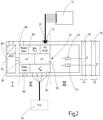
- the device 10 is structurally divided here into three areas I, II, III.
- a voltage supply 68 for the internal components of the new device 10 is arranged in the first area I.
- FIG. The logic units and the inputs are combined in the second area II.
- the third area III includes the safety-related outputs 44, 46 with the associated switching elements 40, 42.
- the interfaces to the outside are indicated here by circles on the housing 70 of the new device, which are preferably spring-loaded terminals.
- the input 32 is designed here as an RJ45 interface and is suitable for accommodating a multi-wire patch cable.
- a transmitter signal is provided by a safe signal transmitter.
- a dedicated measuring system 74 which is arranged on a drive of a movable machine part (not shown here) and failsafely determines a movement variable of the movable machine part.
- the measuring system 74 is preferably a redundant, two-channel system, for example with an optical and magnetic scanning unit, which are arranged on a drive shaft and each provide a signal representative of the movement of the movable machine part.
- other movement variables can also be detected by the measuring system 74, for example by means of acceleration sensors on the moving machine part.
- the measured signals which together represent the encoder signal, are transmitted to the input 32 independently of one another via one wire each of a 6-wire patch cable.
- the transmitter signal is evaluated by the fail-safe evaluation unit 34, which is also designed with two channels of redundancy in this exemplary embodiment.
- the evaluation unit 34 has a first and a second processing unit 36, 38, for example in the form of an FPGA, ASIC or other microcontroller.
- the fail-safe evaluation unit 34 is not only designed to be redundant, but also to be diverse, for example by using functionally identical but structurally different microcontrollers from different manufacturers, as is indicated here by the italics on the second processing unit 38. This design makes it possible for system-related manufacturing errors to be ruled out.
- Two switching elements 40, 41 which each switch a signal path 76, 78 of the safe output 44, 46, are controlled by the fail-safe evaluation unit 34 as a function of the encoder signal.
- the contacts of the switching elements via which the signal paths are routed, are each a break contact and a make contact, which are positively guided to one another.
- a supply voltage for external contactors can be carried out, the contactors dropping out as soon as the associated signal path 76, 78 is opened.
- the fail-safe evaluation unit 34 can determine the number of runs of the movable machine part 18 through a defined range of motion based on the motion variable transmitted with the encoder signal and can provide a redundant switch-off signal via the outputs 44, 46.
- the fail-safe evaluation unit 34 is also designed to switch the outputs 44, 46 when the movement variable itself exceeds a specified threshold value. With the exemplary embodiment shown here, the passages of a movable machine part through a defined range of motion can be determined and a limit or maximum speed of the drive can be monitored at the same time.
- the device can preferably be freely parameterized, for example by storing values for the defined range of movement or the threshold values in a memory 80 .
- the memory 80 is particularly preferably a removable memory, for example a chip or memory card, so that a configuration can be created in a simple manner on a separate device, changed and transferred to the device.
- the device 10 can perform other safety-related tasks in addition to the switch-off function.
- the device 10 has additional outputs 82 via which the switch-off signal or other warning signals can be provided.
- these are preferably small semiconductor outputs.
- Additional warning signals can be provided via the semiconductor outputs, for example if additional movement ranges are defined, exceeding these ranges can trigger a corresponding warning signal.
- the parameterization of the additional movement areas and the threshold values for the warning signals can also be stored in memory 80 .
- a higher-level controller 84 can be, for example, a programmable controller (PLC) that controls the system on the basis of the warning signals in order to prevent the system from being finally switched off by the device.
- PLC programmable controller
- additional inputs are also provided, for example for a reset/start unit 86 and/or a readback unit 88.
- a button (not shown here) can be connected to the reset/start unit 86, with which a button can be used to safely start the system by manually releasing it. The manual release ensures that a person has to confirm that the machine starts up again. The device 10 can thus be reset via the reset/start unit should it have been switched off.
- the switch position of the safe outputs 44, 46 and/or the contactors can preferably be read back via the readback unit 88, via which the device 10 can check its own functionality.
- the device continuously tests its own functionality via the readback unit 88 .
- the device is preferably arranged in a housing 70 and is preferably suitable for mounting on a standard rail.
- the housing can be installed in a control cabinet or be designed for a degree of protection of at least IP54, preferably IP67.
- Figure 3a shows a preferred embodiment for monitoring a circular movement.
- a movable machine part is driven here via a transmission with a spur gear 90 and an internally toothed gear 92 .
- the spur gear 90 is connected to a drive shaft 26, which is itself coupled to a drive, not shown here.
- the drive shaft 26 transmits a rotational speed 28 of the drive to the spur gear 90, which in turn drives the internally toothed gear 92 and, connected therewith, the moving machine part.
- the moving part of the machine is thus rotated proportionally to the speed 28 in a ratio specified by the transmission.
- the range of movement can be defined here by a complete rotation of the internally toothed gear wheel 92 .
- a run through the defined range of motion would thus correspond to a complete revolution of the internally toothed gear wheel 92 .
- the required number of revolutions of the drive shaft 26 can in turn be determined via the transmission ratio of the transmission, which in turn can be determined from the rotational speed, the rotational speed and/or the rotational acceleration in a manner known per se. Rotational acceleration, rotational speed and/or the number of revolutions can therefore all be movement variables within the meaning of the present invention.
- the number of runs through the defined range of motion also depends on the direction of motion of the drive.
- the direction of movement is determined by the direction of rotation of the drive, through which the movable machine part can be moved in a first direction of movement 94 and a second direction of movement 96, which is opposite here, through the defined range of movement.
- the direction of movement 94, 96 must also be determined from the movement quantity in a fail-safe manner using the new device.
- the direction of movement determined in a fail-safe manner can preferably be made available as a further signal via a separate output of the device for further applications.
- ranges of motion can be defined in a simple manner that cannot be directly defined by mechanical limits, for example partial rotations.
- these sub-areas can also be monitored in a fail-safe manner and safe shutdown can be ensured if a sub-area is exceeded. Additional safety-related sensors or actuators are not required for this.
- the number of runs is related here to a fixed point 98 which, for example, represents a rest position of the movable machine part.
- a first and a second area 100, 102 are defined here, with a warning being triggered in each case if the number of runs exceeds one of these areas.
- the warnings can preferably be provided as a separate signal via additional outputs of a higher-level controller.
- a third area 104 marks the switch-off area. If the moving machine part leaves this area, the device provides a fail-safe switch-off signal which, for example, shuts down the drive of the moving machine part reliably and safely.
- the areas can preferably be freely parameterized, so that the device can be easily adapted to changed conditions.
- the present invention is not limited to the monitoring of circular movements as in the Figure 3a shown, limited.
- the monitoring of a translatory movement is indicated as an example.
- a driven via a drive shaft 26 spur gear 90 engages in a rack 106 which is coupled to a movable machine parts, not shown here.
- the rotation of the spur gear 90 is thus converted into a translation.
- one or more defined movement ranges can be defined within the physical limits 108, 110 of the toothed rack 106 and can be monitored in a fail-safe manner by the device according to the invention.
Landscapes
- Engineering & Computer Science (AREA)
- Physics & Mathematics (AREA)
- General Physics & Mathematics (AREA)
- Automation & Control Theory (AREA)
- Human Computer Interaction (AREA)
- Manufacturing & Machinery (AREA)
- Safety Devices In Control Systems (AREA)
- Manipulator (AREA)
Claims (13)
- Dispositif (10) de surveillance protégée contre les erreurs d'un nombre de passages d'une partie de machine mobile (18) par une plage de mouvement définie, comprenantune unité d'évaluation protégée contre les erreurs (34) destinée à fournir un signal de coupure protégé contre les erreurs, etune entrée (32) destinée à enregistrer un signal de codeur qui représente une grandeur de mouvement de la partie de machine mobile (18),caractérisé en ce que l'unité d'évaluation protégée contre les erreurs (34) est réalisée pour déterminer à partir de la grandeur de mouvement un nombre des passages de la partie de machine mobile (18) par la plage de mouvement définie, et pour fournir le signal de coupure protégé contre les erreurs si le nombre déterminé des passages de la partie de machine mobile (18) par la plage de mouvement définie dépasse une première valeur seuil définie, le nombre de passages par la plage de mouvement définie étant dépendant d'une direction de mouvement de la partie de machine mobile (18), et l'unité d'évaluation protégée contre les erreurs (34) étant en outre réalisée pour déterminer sur le plan de la sécurité une première et une deuxième direction de mouvement (94, 96) de la partie de machine mobile (18) à l'aide de la grandeur de mouvement.
- Dispositif selon la revendication 1, comprenant un compteur dans lequel le nombre des passages peut être stocké, le compteur étant incrémenté d'une première quantité définie si la partie de machine mobile (18) est passée entièrement par la plage de mouvement définie dans une première direction de mouvement (94), et est décrémenté d'une deuxième quantité définie si la partie de machine mobile est passée entièrement par la plage de mouvement définie dans une deuxième direction de mouvement (96).
- Dispositif selon la revendication 1 ou 2, comprenant une mémoire (80) dans laquelle une valeur qui représente une limite de la plage de mouvement définie peut être stockée.
- Dispositif selon l'une quelconque des revendications 1 à 3, dans lequel l'unité d'évaluation protégée contre les erreurs (34) est réalisée pour fournir un signal de sortie qui représente la première ou deuxième direction de mouvement (94, 96).
- Dispositif selon l'une quelconque des revendications 1 à 4, dans lequel l'unité d'évaluation protégée contre les erreurs est réalisée pour fournir un signal d'alarme si le nombre des passages de la partie de machine mobile (18) par la plage de mouvement définie dépasse une valeur définie.
- Dispositif selon l'une quelconque des revendications 1 à 5, dans lequel l'unité d'évaluation protégée contre les erreurs (34) est réalisée pour fournir un signal de déblocage si la grandeur de mouvement soupasse une deuxième valeur seuil définie ou représente un arrêt.
- Dispositif selon l'une quelconque des revendications 1 à 6, comprenant un codeur protégé contre les erreurs (74) pour fournir le signal de codeur avec un premier et un deuxième canal de mesure.
- Dispositif selon la revendication 7, dans lequel le codeur protégé contre les erreurs (74) est un codeur rotatif doté d'une unité de balayage optique et/ou magnétique sur un arbre d'entraînement.
- Dispositif selon l'une quelconque des revendications 1 à 8, dans lequel le dispositif présente un premier élément de commutation (40) et un deuxième élément de commutation (42) et le signal de coupure est fourni en fonction de la position de commutateur du premier et du deuxième élément de commutation (40, 42).
- Dispositif selon l'une quelconque des revendications 1 à 9, dans lequel l'unité d'évaluation protégée contre les erreurs (34) est une unité d'évaluation redondante à deux canaux.
- Dispositif selon l'une quelconque des revendications 1 à 10, dans lequel l'unité d'évaluation protégée contre les erreurs (34) présente une première et une deuxième unité de traitement (36, 38) qui produisent respectivement un signal de sortie qui représente le signal de coupure, la première et la deuxième unité de traitement (36, 38) étant réalisées pour se surveiller mutuellement.
- Procédé de surveillance protégée contre les erreurs d'un nombre de passages d'une partie de machine mobile (18) par une plage de mouvement définie, comprenant les étapes consistant à :- enregistrer un signal de codeur qui représente une grandeur de mouvement de la partie de machine mobile (18) au niveau d'une entrée (32) ; et- fournir un signal de coupure protégé contre les erreurs par une unité d'évaluation protégée contre les erreurs (34) ;caractérisé en ce que
l'unité d'évaluation protégée contre les erreurs (34) détermine à partir de la grandeur de mouvement un nombre des passages de la partie de machine mobile (18) par la plage de mouvement définie et fournit le signal de coupure protégé contre les erreurs si le nombre déterminé des passages de la partie de machine mobile (18) par la plage de mouvement définie dépasse une première valeur seuil définie, le nombre de passages par la plage de mouvement définie étant dépendant d'une direction de mouvement de la partie de machine mobile (18), et l'unité d'évaluation protégée contre les erreurs (34) étant en outre réalisée pour déterminer sur le plan de la sécurité une première et une deuxième direction de mouvement (94, 96) de la partie de machine mobile (18) à l'aide de la grandeur de mouvement. - Programme informatique comprenant du code programme qui est réalisé pour effectuer le procédé selon la revendication 12 si le code programme est exécuté sur un processeur d'un dispositif selon les revendications 1 à 11.
Applications Claiming Priority (2)
| Application Number | Priority Date | Filing Date | Title |
|---|---|---|---|
| DE102014106166.7A DE102014106166B4 (de) | 2014-05-02 | 2014-05-02 | Vorrichtung und Verfahren zum fehlersicheren Überwachen eines beweglichen Maschinenteils |
| PCT/EP2015/059532 WO2015166058A1 (fr) | 2014-05-02 | 2015-04-30 | Dispositif et procédé de surveillance d'une partie de machine mobile avec protection contre les erreurs |
Publications (2)
| Publication Number | Publication Date |
|---|---|
| EP3137948A1 EP3137948A1 (fr) | 2017-03-08 |
| EP3137948B1 true EP3137948B1 (fr) | 2022-03-23 |
Family
ID=53189010
Family Applications (1)
| Application Number | Title | Priority Date | Filing Date |
|---|---|---|---|
| EP15723163.0A Active EP3137948B1 (fr) | 2014-05-02 | 2015-04-30 | Dispositif et procédé de surveillance d'une partie de machine mobile avec protection contre les erreurs |
Country Status (6)
| Country | Link |
|---|---|
| US (1) | US10310484B2 (fr) |
| EP (1) | EP3137948B1 (fr) |
| JP (1) | JP2017517085A (fr) |
| CN (1) | CN106255928B (fr) |
| DE (1) | DE102014106166B4 (fr) |
| WO (1) | WO2015166058A1 (fr) |
Families Citing this family (5)
| Publication number | Priority date | Publication date | Assignee | Title |
|---|---|---|---|---|
| EP3382735B1 (fr) * | 2017-03-31 | 2019-05-08 | Sick AG | Commande de sécurité modulaire destiné à la commande sécurisée d'au moins une machine |
| DE102018120344B4 (de) * | 2018-08-21 | 2024-11-21 | Pilz Gmbh & Co. Kg | Automatisierungssystem zur Überwachung eines sicherheitskritischen Prozesses |
| DE102019216268A1 (de) * | 2019-10-23 | 2021-04-29 | Robert Bosch Gmbh | Verfahren zum Erkennen einer Blockierung eines Gleichstrommotors |
| DE102020115307A1 (de) | 2020-06-09 | 2021-12-09 | Sick Ag | Bedienvorrichtung für eine Sicherheitszuhaltung |
| CN120185919B (zh) * | 2025-04-28 | 2025-09-23 | 国网甘肃省电力公司天水供电公司 | 基于智能水晶头的网络边界防护感知系统及方法 |
Family Cites Families (16)
| Publication number | Priority date | Publication date | Assignee | Title |
|---|---|---|---|---|
| JPS5418196Y2 (fr) * | 1973-02-27 | 1979-07-10 | ||
| DE3837218A1 (de) * | 1988-11-02 | 1990-05-03 | Elektronik Geraetewerk Gmbh | Kriech- und drehbewegungsueberwachung bei schutzeinrichtung mit normaler oder erhoehter sicherheit typ ebud-00 (...99) |
| US5047752A (en) * | 1989-11-14 | 1991-09-10 | Murata Wiedemann, Inc. | Safety system for a machine tool |
| DE4432768C2 (de) * | 1994-09-14 | 1997-02-13 | Gemac Ges Fuer Mikroelektronik | Schaltungsanordnung zur Überwachung sicherheitsrelevanter Maschinenparameter und Betriebszustände bei Bewegungsvorgängen |
| JP5062925B2 (ja) * | 1997-12-06 | 2012-10-31 | エラン・シャルトエレメンテ・ゲーエムベーハー・ウント・コンパニー・カーゲー | 技術設備のための監視・制御装置 |
| DE19920299B4 (de) * | 1999-05-03 | 2008-01-03 | Siemens Ag | Verfahren sowie Vorrichtung zur Erfassung, Übertragung und Verarbeitung sicherheitsgerichteter Signale |
| US6276916B1 (en) * | 1999-06-30 | 2001-08-21 | Husky Injection Molding Systems Ltd. | Failsafe shooting pot actuator for an injection molding machine |
| AT501688B1 (de) * | 2005-04-08 | 2008-02-15 | Keba Ag | Verfahren sowie vorrichtung zur sicheren, verwechslungsfreien und ausschliesslichen zuordnung der befehlsgewalt einer bedienperson zu einer steuerbaren technischen einrichtung |
| DE102005057588A1 (de) * | 2005-06-14 | 2007-01-04 | Elan Schaltelemente Gmbh & Co. Kg | Maschinensteuerung für eine gefahrbringende Aktionen ausführende Maschine wie Presse mit zumindest einem Abschaltpfad |
| DE102006046286A1 (de) * | 2005-12-16 | 2007-06-21 | Siemens Ag | Bewegungsüberwachung |
| DE102006032226B4 (de) * | 2006-07-07 | 2009-12-10 | Pilz Gmbh & Co. Kg | Verfahren und Vorrichtung zur sicheren Abstandsüberwachung |
| DE102007063099A1 (de) * | 2007-12-28 | 2009-07-02 | Kuka Roboter Gmbh | Roboter und Verfahren zum Überwachen der Momente an einem solchen |
| JP2010152595A (ja) * | 2008-12-25 | 2010-07-08 | Omron Corp | サーボシステムおよび安全制御機器 |
| EP2504900B1 (fr) * | 2009-11-23 | 2018-04-18 | Pilz GmbH & Co. KG | Circuit de sécurité et méthode pour une surveillance sûre d'un mouvement |
| EP2772676B1 (fr) * | 2011-05-18 | 2015-07-08 | Sick Ag | Caméra 3D et procédé de surveillance tridimensionnel d'un domaine de surveillance |
| JP5970880B2 (ja) * | 2012-03-15 | 2016-08-17 | オムロン株式会社 | 動力源の制御装置 |
-
2014
- 2014-05-02 DE DE102014106166.7A patent/DE102014106166B4/de active Active
-
2015
- 2015-04-30 EP EP15723163.0A patent/EP3137948B1/fr active Active
- 2015-04-30 JP JP2017508763A patent/JP2017517085A/ja active Pending
- 2015-04-30 CN CN201580022308.9A patent/CN106255928B/zh not_active Expired - Fee Related
- 2015-04-30 WO PCT/EP2015/059532 patent/WO2015166058A1/fr not_active Ceased
-
2016
- 2016-10-27 US US15/336,050 patent/US10310484B2/en active Active
Also Published As
| Publication number | Publication date |
|---|---|
| JP2017517085A (ja) | 2017-06-22 |
| CN106255928B (zh) | 2024-06-07 |
| DE102014106166B4 (de) | 2026-01-29 |
| EP3137948A1 (fr) | 2017-03-08 |
| WO2015166058A1 (fr) | 2015-11-05 |
| US10310484B2 (en) | 2019-06-04 |
| US20170045878A1 (en) | 2017-02-16 |
| DE102014106166A1 (de) | 2015-11-05 |
| CN106255928A (zh) | 2016-12-21 |
Similar Documents
| Publication | Publication Date | Title |
|---|---|---|
| EP3782773B1 (fr) | Outil pour un robot collaborant, robot pourvu d'outil fixé audit robot ainsi que procédé de protection contre la collision | |
| EP2353052B1 (fr) | Commande de sécurité et procédé de commande d une installation automatisée | |
| EP2637067B1 (fr) | Agencement de capteur destiné à détecter l'état sécurisé d'une installation pour une installation automatisée | |
| EP2422244B1 (fr) | Commande de sécurité et procédé de commande d'une installation automatisée | |
| EP2715462B1 (fr) | Procédé pour faire fonctionner un appareil de commande de sécurité | |
| WO2006103249A2 (fr) | Procede et dispositif de commande pour la reaction ciblee en cas de contact entre un element d'une machine et un objet | |
| WO2010060572A1 (fr) | Commande de sécurité et procédé de commande d'une installation automatisée | |
| DE102013013875A1 (de) | Verfahren zum Steuern eines Roboters | |
| DE102014106166B4 (de) | Vorrichtung und Verfahren zum fehlersicheren Überwachen eines beweglichen Maschinenteils | |
| DE102006046286A1 (de) | Bewegungsüberwachung | |
| EP1253490A2 (fr) | Procédé et dispositif de surveillance sécurisée de la vitesse | |
| EP4059678B1 (fr) | Procédé et machine de coupe avec inversement par contrôle sécuritaire du mouvement dangereux de la lame de coupe en cas de danger | |
| EP2671690B1 (fr) | Unité d'évaluation d'un appareil de commutation de sécurité et appareil de commutation de sécurité | |
| EP2177439B1 (fr) | Unité de fabrication et procédé de fonctionnement de l'unité de fabrication | |
| DE4432768C2 (de) | Schaltungsanordnung zur Überwachung sicherheitsrelevanter Maschinenparameter und Betriebszustände bei Bewegungsvorgängen | |
| EP3963611B1 (fr) | Ensemble commutateur comprenant un système d'entraînement | |
| DE3837218C2 (fr) | ||
| DE102020203598A1 (de) | Steuersystem für eine industriemaschine | |
| EP3447540B1 (fr) | Rideau lumineux | |
| DE102004019284A1 (de) | Vorrichtung zum Betrieb eines Synchronmotors | |
| EP2511053B1 (fr) | Circuit et procédé de surveillance d'un dispositif vecteur de danger par évaluation de l'accélération | |
| EP3504596B1 (fr) | Optimisation automatique du paramétrage de contrôleur de mouvement | |
| DE4432759A1 (de) | Variabler Sicherheitsmodul zur Überwachung und Steuerung sicherheitsrelevanter Maschinenparamter und Betriebszustände | |
| DE102006061310A1 (de) | Vorrichtung zum Bewegen von Massen mittels einer Welle, die über einen motorischen Antrieb, ggf. mit unterschiedlichen Winkelgeschwindigkeiten antreibbar ist, und Verwendung einer derartigen Vorrichtung bei einem Drehtisch mit Schrittantrieb | |
| EP3957423A1 (fr) | Architecture de sécurité pour machines d'usinage du bois |
Legal Events
| Date | Code | Title | Description |
|---|---|---|---|
| STAA | Information on the status of an ep patent application or granted ep patent |
Free format text: STATUS: THE INTERNATIONAL PUBLICATION HAS BEEN MADE |
|
| PUAI | Public reference made under article 153(3) epc to a published international application that has entered the european phase |
Free format text: ORIGINAL CODE: 0009012 |
|
| STAA | Information on the status of an ep patent application or granted ep patent |
Free format text: STATUS: REQUEST FOR EXAMINATION WAS MADE |
|
| 17P | Request for examination filed |
Effective date: 20161108 |
|
| AK | Designated contracting states |
Kind code of ref document: A1 Designated state(s): AL AT BE BG CH CY CZ DE DK EE ES FI FR GB GR HR HU IE IS IT LI LT LU LV MC MK MT NL NO PL PT RO RS SE SI SK SM TR |
|
| AX | Request for extension of the european patent |
Extension state: BA ME |
|
| DAV | Request for validation of the european patent (deleted) | ||
| DAX | Request for extension of the european patent (deleted) | ||
| STAA | Information on the status of an ep patent application or granted ep patent |
Free format text: STATUS: EXAMINATION IS IN PROGRESS |
|
| 17Q | First examination report despatched |
Effective date: 20200723 |
|
| GRAP | Despatch of communication of intention to grant a patent |
Free format text: ORIGINAL CODE: EPIDOSNIGR1 |
|
| STAA | Information on the status of an ep patent application or granted ep patent |
Free format text: STATUS: GRANT OF PATENT IS INTENDED |
|
| INTG | Intention to grant announced |
Effective date: 20210324 |
|
| GRAJ | Information related to disapproval of communication of intention to grant by the applicant or resumption of examination proceedings by the epo deleted |
Free format text: ORIGINAL CODE: EPIDOSDIGR1 |
|
| STAA | Information on the status of an ep patent application or granted ep patent |
Free format text: STATUS: EXAMINATION IS IN PROGRESS |
|
| INTC | Intention to grant announced (deleted) | ||
| GRAP | Despatch of communication of intention to grant a patent |
Free format text: ORIGINAL CODE: EPIDOSNIGR1 |
|
| STAA | Information on the status of an ep patent application or granted ep patent |
Free format text: STATUS: GRANT OF PATENT IS INTENDED |
|
| INTG | Intention to grant announced |
Effective date: 20211004 |
|
| GRAS | Grant fee paid |
Free format text: ORIGINAL CODE: EPIDOSNIGR3 |
|
| GRAA | (expected) grant |
Free format text: ORIGINAL CODE: 0009210 |
|
| STAA | Information on the status of an ep patent application or granted ep patent |
Free format text: STATUS: THE PATENT HAS BEEN GRANTED |
|
| AK | Designated contracting states |
Kind code of ref document: B1 Designated state(s): AL AT BE BG CH CY CZ DE DK EE ES FI FR GB GR HR HU IE IS IT LI LT LU LV MC MK MT NL NO PL PT RO RS SE SI SK SM TR |
|
| REG | Reference to a national code |
Ref country code: GB Ref legal event code: FG4D Free format text: NOT ENGLISH |
|
| REG | Reference to a national code |
Ref country code: CH Ref legal event code: EP |
|
| REG | Reference to a national code |
Ref country code: IE Ref legal event code: FG4D Free format text: LANGUAGE OF EP DOCUMENT: GERMAN |
|
| REG | Reference to a national code |
Ref country code: DE Ref legal event code: R096 Ref document number: 502015015711 Country of ref document: DE |
|
| REG | Reference to a national code |
Ref country code: AT Ref legal event code: REF Ref document number: 1477873 Country of ref document: AT Kind code of ref document: T Effective date: 20220415 |
|
| REG | Reference to a national code |
Ref country code: LT Ref legal event code: MG9D |
|
| REG | Reference to a national code |
Ref country code: NL Ref legal event code: MP Effective date: 20220323 |
|
| PG25 | Lapsed in a contracting state [announced via postgrant information from national office to epo] |
Ref country code: SE Free format text: LAPSE BECAUSE OF FAILURE TO SUBMIT A TRANSLATION OF THE DESCRIPTION OR TO PAY THE FEE WITHIN THE PRESCRIBED TIME-LIMIT Effective date: 20220323 Ref country code: RS Free format text: LAPSE BECAUSE OF FAILURE TO SUBMIT A TRANSLATION OF THE DESCRIPTION OR TO PAY THE FEE WITHIN THE PRESCRIBED TIME-LIMIT Effective date: 20220323 Ref country code: NO Free format text: LAPSE BECAUSE OF FAILURE TO SUBMIT A TRANSLATION OF THE DESCRIPTION OR TO PAY THE FEE WITHIN THE PRESCRIBED TIME-LIMIT Effective date: 20220623 Ref country code: LT Free format text: LAPSE BECAUSE OF FAILURE TO SUBMIT A TRANSLATION OF THE DESCRIPTION OR TO PAY THE FEE WITHIN THE PRESCRIBED TIME-LIMIT Effective date: 20220323 Ref country code: HR Free format text: LAPSE BECAUSE OF FAILURE TO SUBMIT A TRANSLATION OF THE DESCRIPTION OR TO PAY THE FEE WITHIN THE PRESCRIBED TIME-LIMIT Effective date: 20220323 Ref country code: BG Free format text: LAPSE BECAUSE OF FAILURE TO SUBMIT A TRANSLATION OF THE DESCRIPTION OR TO PAY THE FEE WITHIN THE PRESCRIBED TIME-LIMIT Effective date: 20220623 |
|
| PG25 | Lapsed in a contracting state [announced via postgrant information from national office to epo] |
Ref country code: LV Free format text: LAPSE BECAUSE OF FAILURE TO SUBMIT A TRANSLATION OF THE DESCRIPTION OR TO PAY THE FEE WITHIN THE PRESCRIBED TIME-LIMIT Effective date: 20220323 Ref country code: GR Free format text: LAPSE BECAUSE OF FAILURE TO SUBMIT A TRANSLATION OF THE DESCRIPTION OR TO PAY THE FEE WITHIN THE PRESCRIBED TIME-LIMIT Effective date: 20220624 Ref country code: FI Free format text: LAPSE BECAUSE OF FAILURE TO SUBMIT A TRANSLATION OF THE DESCRIPTION OR TO PAY THE FEE WITHIN THE PRESCRIBED TIME-LIMIT Effective date: 20220323 |
|
| PG25 | Lapsed in a contracting state [announced via postgrant information from national office to epo] |
Ref country code: NL Free format text: LAPSE BECAUSE OF FAILURE TO SUBMIT A TRANSLATION OF THE DESCRIPTION OR TO PAY THE FEE WITHIN THE PRESCRIBED TIME-LIMIT Effective date: 20220323 |
|
| PG25 | Lapsed in a contracting state [announced via postgrant information from national office to epo] |
Ref country code: SM Free format text: LAPSE BECAUSE OF FAILURE TO SUBMIT A TRANSLATION OF THE DESCRIPTION OR TO PAY THE FEE WITHIN THE PRESCRIBED TIME-LIMIT Effective date: 20220323 Ref country code: SK Free format text: LAPSE BECAUSE OF FAILURE TO SUBMIT A TRANSLATION OF THE DESCRIPTION OR TO PAY THE FEE WITHIN THE PRESCRIBED TIME-LIMIT Effective date: 20220323 Ref country code: RO Free format text: LAPSE BECAUSE OF FAILURE TO SUBMIT A TRANSLATION OF THE DESCRIPTION OR TO PAY THE FEE WITHIN THE PRESCRIBED TIME-LIMIT Effective date: 20220323 Ref country code: PT Free format text: LAPSE BECAUSE OF FAILURE TO SUBMIT A TRANSLATION OF THE DESCRIPTION OR TO PAY THE FEE WITHIN THE PRESCRIBED TIME-LIMIT Effective date: 20220725 Ref country code: ES Free format text: LAPSE BECAUSE OF FAILURE TO SUBMIT A TRANSLATION OF THE DESCRIPTION OR TO PAY THE FEE WITHIN THE PRESCRIBED TIME-LIMIT Effective date: 20220323 Ref country code: EE Free format text: LAPSE BECAUSE OF FAILURE TO SUBMIT A TRANSLATION OF THE DESCRIPTION OR TO PAY THE FEE WITHIN THE PRESCRIBED TIME-LIMIT Effective date: 20220323 Ref country code: CZ Free format text: LAPSE BECAUSE OF FAILURE TO SUBMIT A TRANSLATION OF THE DESCRIPTION OR TO PAY THE FEE WITHIN THE PRESCRIBED TIME-LIMIT Effective date: 20220323 |
|
| PG25 | Lapsed in a contracting state [announced via postgrant information from national office to epo] |
Ref country code: PL Free format text: LAPSE BECAUSE OF FAILURE TO SUBMIT A TRANSLATION OF THE DESCRIPTION OR TO PAY THE FEE WITHIN THE PRESCRIBED TIME-LIMIT Effective date: 20220323 Ref country code: IS Free format text: LAPSE BECAUSE OF FAILURE TO SUBMIT A TRANSLATION OF THE DESCRIPTION OR TO PAY THE FEE WITHIN THE PRESCRIBED TIME-LIMIT Effective date: 20220723 Ref country code: AL Free format text: LAPSE BECAUSE OF FAILURE TO SUBMIT A TRANSLATION OF THE DESCRIPTION OR TO PAY THE FEE WITHIN THE PRESCRIBED TIME-LIMIT Effective date: 20220323 |
|
| REG | Reference to a national code |
Ref country code: DE Ref legal event code: R097 Ref document number: 502015015711 Country of ref document: DE |
|
| REG | Reference to a national code |
Ref country code: BE Ref legal event code: MM Effective date: 20220430 |
|
| PLBE | No opposition filed within time limit |
Free format text: ORIGINAL CODE: 0009261 |
|
| STAA | Information on the status of an ep patent application or granted ep patent |
Free format text: STATUS: NO OPPOSITION FILED WITHIN TIME LIMIT |
|
| PG25 | Lapsed in a contracting state [announced via postgrant information from national office to epo] |
Ref country code: MC Free format text: LAPSE BECAUSE OF FAILURE TO SUBMIT A TRANSLATION OF THE DESCRIPTION OR TO PAY THE FEE WITHIN THE PRESCRIBED TIME-LIMIT Effective date: 20220323 Ref country code: LU Free format text: LAPSE BECAUSE OF NON-PAYMENT OF DUE FEES Effective date: 20220430 Ref country code: DK Free format text: LAPSE BECAUSE OF FAILURE TO SUBMIT A TRANSLATION OF THE DESCRIPTION OR TO PAY THE FEE WITHIN THE PRESCRIBED TIME-LIMIT Effective date: 20220323 |
|
| PG25 | Lapsed in a contracting state [announced via postgrant information from national office to epo] |
Ref country code: BE Free format text: LAPSE BECAUSE OF NON-PAYMENT OF DUE FEES Effective date: 20220430 |
|
| 26N | No opposition filed |
Effective date: 20230102 |
|
| GBPC | Gb: european patent ceased through non-payment of renewal fee |
Effective date: 20220623 |
|
| PG25 | Lapsed in a contracting state [announced via postgrant information from national office to epo] |
Ref country code: IE Free format text: LAPSE BECAUSE OF NON-PAYMENT OF DUE FEES Effective date: 20220430 |
|
| PG25 | Lapsed in a contracting state [announced via postgrant information from national office to epo] |
Ref country code: SI Free format text: LAPSE BECAUSE OF FAILURE TO SUBMIT A TRANSLATION OF THE DESCRIPTION OR TO PAY THE FEE WITHIN THE PRESCRIBED TIME-LIMIT Effective date: 20220323 Ref country code: GB Free format text: LAPSE BECAUSE OF NON-PAYMENT OF DUE FEES Effective date: 20220623 |
|
| PG25 | Lapsed in a contracting state [announced via postgrant information from national office to epo] |
Ref country code: HU Free format text: LAPSE BECAUSE OF FAILURE TO SUBMIT A TRANSLATION OF THE DESCRIPTION OR TO PAY THE FEE WITHIN THE PRESCRIBED TIME-LIMIT; INVALID AB INITIO Effective date: 20150430 |
|
| PG25 | Lapsed in a contracting state [announced via postgrant information from national office to epo] |
Ref country code: MK Free format text: LAPSE BECAUSE OF FAILURE TO SUBMIT A TRANSLATION OF THE DESCRIPTION OR TO PAY THE FEE WITHIN THE PRESCRIBED TIME-LIMIT Effective date: 20220323 Ref country code: CY Free format text: LAPSE BECAUSE OF FAILURE TO SUBMIT A TRANSLATION OF THE DESCRIPTION OR TO PAY THE FEE WITHIN THE PRESCRIBED TIME-LIMIT Effective date: 20220323 |
|
| PG25 | Lapsed in a contracting state [announced via postgrant information from national office to epo] |
Ref country code: MT Free format text: LAPSE BECAUSE OF FAILURE TO SUBMIT A TRANSLATION OF THE DESCRIPTION OR TO PAY THE FEE WITHIN THE PRESCRIBED TIME-LIMIT Effective date: 20220323 |
|
| PGFP | Annual fee paid to national office [announced via postgrant information from national office to epo] |
Ref country code: DE Payment date: 20250526 Year of fee payment: 11 |
|
| PGFP | Annual fee paid to national office [announced via postgrant information from national office to epo] |
Ref country code: IT Payment date: 20250424 Year of fee payment: 11 |
|
| PGFP | Annual fee paid to national office [announced via postgrant information from national office to epo] |
Ref country code: FR Payment date: 20250425 Year of fee payment: 11 |
|
| PGFP | Annual fee paid to national office [announced via postgrant information from national office to epo] |
Ref country code: CH Payment date: 20250501 Year of fee payment: 11 |
|
| PGFP | Annual fee paid to national office [announced via postgrant information from national office to epo] |
Ref country code: AT Payment date: 20250423 Year of fee payment: 11 |
|
| PG25 | Lapsed in a contracting state [announced via postgrant information from national office to epo] |
Ref country code: TR Free format text: LAPSE BECAUSE OF FAILURE TO SUBMIT A TRANSLATION OF THE DESCRIPTION OR TO PAY THE FEE WITHIN THE PRESCRIBED TIME-LIMIT Effective date: 20220323 |
|
| REG | Reference to a national code |
Ref country code: CH Ref legal event code: U11 Free format text: ST27 STATUS EVENT CODE: U-0-0-U10-U11 (AS PROVIDED BY THE NATIONAL OFFICE) Effective date: 20260501 |