EP3137954B1 - Verfahren zur kalibrierung des werkzeugmittelpunkts für industrierobotersystem - Google Patents
Verfahren zur kalibrierung des werkzeugmittelpunkts für industrierobotersystem Download PDFInfo
- Publication number
- EP3137954B1 EP3137954B1 EP14890545.8A EP14890545A EP3137954B1 EP 3137954 B1 EP3137954 B1 EP 3137954B1 EP 14890545 A EP14890545 A EP 14890545A EP 3137954 B1 EP3137954 B1 EP 3137954B1
- Authority
- EP
- European Patent Office
- Prior art keywords
- tool
- industrial robot
- cross beam
- posture
- beam sensor
- Prior art date
- Legal status (The legal status is an assumption and is not a legal conclusion. Google has not performed a legal analysis and makes no representation as to the accuracy of the status listed.)
- Active
Links
Images
Classifications
-
- B—PERFORMING OPERATIONS; TRANSPORTING
- B25—HAND TOOLS; PORTABLE POWER-DRIVEN TOOLS; MANIPULATORS
- B25J—MANIPULATORS; CHAMBERS PROVIDED WITH MANIPULATION DEVICES
- B25J9/00—Program-controlled manipulators
- B25J9/16—Program controls
- B25J9/1679—Program controls characterised by the tasks executed
- B25J9/1692—Calibration of manipulator
-
- G—PHYSICS
- G05—CONTROLLING; REGULATING
- G05B—CONTROL OR REGULATING SYSTEMS IN GENERAL; FUNCTIONAL ELEMENTS OF SUCH SYSTEMS; MONITORING OR TESTING ARRANGEMENTS FOR SUCH SYSTEMS OR ELEMENTS
- G05B2219/00—Program-control systems
- G05B2219/30—Nc systems
- G05B2219/39—Robotics, robotics to robotics hand
- G05B2219/39024—Calibration of manipulator
-
- G—PHYSICS
- G05—CONTROLLING; REGULATING
- G05B—CONTROL OR REGULATING SYSTEMS IN GENERAL; FUNCTIONAL ELEMENTS OF SUCH SYSTEMS; MONITORING OR TESTING ARRANGEMENTS FOR SUCH SYSTEMS OR ELEMENTS
- G05B2219/00—Program-control systems
- G05B2219/30—Nc systems
- G05B2219/39—Robotics, robotics to robotics hand
- G05B2219/39025—Spheric tool interrupts transmitted calibration beam, in different configurations
Definitions
- the invention relates to a method for calibrating a tool centre point, and more particularly to calibrating a tool centre point for an industrial robot system.
- Calibration is the typical way to ensure the position accuracy between the industrial robot and its tool or between the industrial robot and its work object in the industrial robot cell.
- the tool and the work object may be defined with inaccurate kinematical data. So that, a good calibration makes it possible to align the off-line program with the on-line, and it can also recover the cell once the relative position between robot and the tool or the work object gets changed.
- US Patent 7, 684, 898 describes a method for calibration of a working point (TCP) for tools on industrial robots with a calibration device includes the use of at least two light barriers with an azimuth angle greater than zero at an angle to each other and intersecting at an intersection point.
- the method includes fixing set TCP positional coordinates for a set working point for the tool, relative to a tool reference point and a TCP coordinate system relative to the working point, moving the tool to the set working point with relation to the TCP coordinate system through the light barriers, such that the tool tip interrupts the light barriers, recording actual TCP positional coordinates determining the difference between the set TCP positional coordinates for the interruption of the light barriers for a set working point and the corresponding recorded actual TCP positional coordinates for the actual working point, calculating the actual working point from the set working point for the number of levels of light barriers from the differences and the known position and azimuth angles (a) of the light barriers.
- This calibration method requires the knowledge of the position and azimuth angles of the light barriers, however this method requires a predefined tool data and can only work with one posture without covering post inaccuracy introduced by the manipulator.
- DE 10 2007 020604 A1 discloses a device having a light receiver for capturing of light intensity differences in a measuring plane.
- the light receiver is arranged in a housing, which has a passage opening perpendicular to the measuring plane and on their length a gap is formed in the housing, through which light in the measuring plane meets on the light receiver.
- An independent claim is also included for a method for contactless positioning of an object, particularly a tool of an industrial robot.
- US 2008/234863 A1 discloses a method for calibration of a working point (TCP) for tools on industrial robots with a calibration device, comprising at least two light barriers with an azimuth angle (alpha) greater than zero at an angle to each other and intersecting at an intersection point (R), comprising the steps:; a) fixing set TCP positional coordinates for a set working point for the tool, relative to a tool reference point (W) of the industrial robot and a TCP coordinate system relative to the working point (TCP), b) moving the tool directly to the set working point with relation to the TCP coordinate system through the light barriers, such that the tool tip of the tool, corresponding to the working point (TCP), interrupts the light E barriers, c) recording actual TCP positional coordinates on interruption of a light barrier, d) determination of the difference between the set TCP positional coordinates for the interruption of the light barriers for a set working point and the corresponding recorded actual TCP positional coordinates for the actual working point, e); calculation of deviation of the
- a method for calibrating a tool centre point of tool for an industrial robot system comprising a cross beam sensor that has a first beam and a second beam which are angled to each other with a vertex angle greater than zero and cross each other at a crossing point, including: (a) relatively moving a first part of said tool and a cross beam sensor by said industrial robot with translational motion in an orientation so that said first part of said tool respectively interrupts said first beam and said second beam of said cross beam sensor; (b) recording a first posture and a second posture of said industrial robot during the interruptions of said first beam and said second beam of said cross beam sensor by said first part of said tool; (c) relatively moving a second part of said tool and said cross beam sensor by said industrial robot with translational motion in said orientation so that said second part of said tool respectively interrupts said first beam and said second beam of said cross beam sensor; (d) recording a third posture and a fourth posture of said industrial robot during the interruptions of said first beam and said second beam of said cross beam sensor by
- a method for calibrating a tool centre point of tool for an industrial robot system comprising a cross beam sensor that has a first beam and a second beam which are angled to each other with a vertex angle greater than zero and cross each other at a crossing point, including: (a) relatively moving a first part of said tool and a cross beam sensor by said industrial robot with translational motion in an orientation so that said first part of said tool interrupts said first beam of said cross beam sensor, moves along the first beam direction from the interruption point, and interrupts said second beam of said cross beam sensor at said crossing point of said cross beam sensor; (b) recording a second posture of said industrial robot where said first part of said tool interrupts said second beam of said cross beam sensor at said crossing point of said cross beam sensor; (c) relatively moving a second part of said tool and said cross beam sensor by said industrial robot with translational motion in said orientation so that said second part of said tool interrupts said first/second beam of said cross beam sensor, moves along the first/second beam direction from the interruption point,
- the industrial robot can guide the cross beam sensor to approach TCP of the tool.
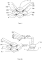
- Figure 1 shows a cross beam sensor according to an embodiment of present invention.
- the cross beam sensor has at least two optical beams which are angled to one another with a vertex angle greater than zero and cross one another at a crossing point.
- the cross beam sensor 1 has a flat block 10 with a hole 11 through it, and a first transmitter 12a, a first receiver 12b, a second transmitter 13a, a second receiver 13b.
- the hole 11 has an internal surface shaped like a cylinder or a hexagon.
- the first transmitter 12a, the first receiver 12b, the second transmitter 13a, and the second receiver 13b are respectively fixed on the positions P1, P2, P3, and P4 so that a first beam 14a sent by the first transmitter 12a can arrive at the first receiver 12b, and a second beam 14b sent by the second transmitter 13a can arrive at the second receiver 13b, and the first beam 14a and the second beam 14b are aligned diagonally thereto; the first beam 14a and the second beam 14b run up to one another at a vertex angel alpha greater than zero, for example 90 degrees and meet at a crossing point R in the interspace between the beams 14a, 14b.
- the cross beam sensor 1 can be mounted in a stationary fashion in the cell of an industrial robot.
- a tool center point (TCP) of a tool for an industrial robot, for example, the tool tip, is moved for the purpose of calibrating the tool center point TCP so as to approach the crossing point R of the cross beam sensor 1.
- both of the first beam 14a and the second beam 14b are interrupted by the tool tip such that a switching signal is generated.
- the calibration method is explained in more detail below.
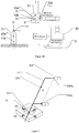
- Figures 2A and 2B respectively show an industrial robot system for calibrating a tool centre point according to embodiments of present invention concerning scenarios A and B.
- the industrial robot system 2 includes an industrial robot 20, a tool 21, and the cross beam sensor 1.
- Tool calibration is to identify the pose of the tool 21 with respect to a part of the industrial robot 20, for example its wrist 200.
- the tool 21 is held by the industrial robot 20 (for example attached to a wrist of the industrial robot), and the cross beam sensor 1 is mounted in the industrial robot cell in a stationary fashion.
- the tool calibration for scenario A is to identify the fixed relative pose of the tool 21 with respect to the wrist 200 of the industrial robot 20.
- the TCP four-point calibration is done by moving the robot making the TCP point against a fixed point in a surrounding to the industrial robot.
- the fixed point is for instance the tip of a nail.
- the coordinate of the TCP in relation to the robot base coordinate/world coordinate system is calculated. This is done by formulating a least squares optimization problem by insisting that if the correct coordinates of the TCP pointer are found, then the sum of the squared variations in the calculated location of the fixed pointer is minimal, ideally zero, but allowing for a small residual error due to inaccuracies in motions and robot kinematics.
- the industrial robot 20 needs to make relative movement between the tool 21 and the cross beam sensor 1 so that the tool centre point of the tool 21 can approach the crossing point R of the cross beam sensor 1.
- step (a) the industrial robot 20 holds the tool 21 and relatively move a first part 21a of the tool 21 and the cross beam sensor 1 with translational motion in an orientation O so that the first part 21a of the tool 21 respectively interrupts the first beam 14a and the second beam 14b of the cross beam sensor 1.
- the cross beam sensor 1 upon interruption of the first beam 14a, the cross beam sensor 1 sends a first signal to the industrial robot system 2 representing that the interruption of the first beam 14a occurs, and upon interruption of the second beam 14b, the cross beam sensor 1 sends a second signal to the industrial robot system 2 representing that the interruption of the second beam 14b occurs; the characteristic of translational movement renders the tool 21 retains the same orientation when it moves relatively to the cross beam sensor 1 and the first part 21 of the tool 21 interrupts the first beam 14a and the second beam 14b in the plane defined by the two beams.
- Step (b) records a first posture and a second posture of the industrial robot 20 during the interruptions of the first beam 14a and the second beam 14b of the cross beam sensor 1 by the first part 21a of the tool 21.
- the first posture of the industrial robot 20 from which the coordinates for any part of the industrial robot 20 can be calculated according to various coordinate system, for example the coordinates of TCP0 representing the position of the industrial robot wrist 200 with respect to the industrial robot base coordinate system/world coordinate system; the second posture of the industrial robot 20 is also recorded upon interruption of the second beam 14b by the first part 21a of the tool 21.
- the posture of the industrial robot 20 for the first part 21a of the tool 21 intersecting with the intersecting point R of the first beam 14a and the second beam 14b of the cross beam sensor 1 can be solved.
- the first beam direction D 1 and the second beam direction D 2 can be represented with respect to the robot base coordinate/world coordinate system.
- this said posture of the industrial robot 20 is the coordinates of TCP0 representing the position of the industrial robot wrist 200 with respect to the industrial robot base coordinate system/world coordinate system and denoted as TCP0 1 .
- step (c) the industrial robot 20 holds the tool 21 and relatively move a second part 21b of the tool 21 and the cross beam sensor 1 with translational motion in the same orientation O as used in step (a) so that the second part 21b of the tool 21 respectively interrupts the first beam 14a and the second beam 14b of the cross beam sensor 1.
- the cross beam sensor 1 upon interruption of the second beam 14a, the cross beam sensor 1 sends a third signal to the industrial robot system 2 representing that the interruption of the first beam 14a occurs, and upon interruption of the second beam 14b, the cross beam sensor 1 sends a fourth signal to the industrial robot system 2 representing that the interruption of the second beam 14b occurs; the characteristic of translational movement renders the tool 21 retains the same orientation when it moves relatively to the cross beam sensor 1 and the first part 21 of the tool 21 interrupts the first beam 14a and the second beam 14b in the plane defined by the two beams.
- Step (d) records a third posture and a fourth posture of the industrial robot 20 during the interruptions of the first beam 14a and the second beam 14b of the cross beam sensor 1 by the second part 21b of the tool 21.
- the first beam 14a upon the interruption of the first beam 14a, it records the third posture of the industrial robot 20 from which the coordinates for any part of the industrial robot 20 can be calculated according to various coordinate system by using known industrial robot kinematics, for example the coordinates for representing the position of the industrial robot wrist with respect to the industrial robot base coordinate system/world coordinate system; the fourth posture of the industrial robot 20 is also recorded upon interruption of the second beam 14b by the second part 21b of the tool 21.
- the posture of the industrial robot 20 for the second part 21b of the tool 21 intersecting with the intersecting point R of the first beam 14a and the second beam 14b of the cross beam sensor 1 can be solved.
- the first beam direction D 1 and the second beam direction D 2 can be represented with respect to the robot base coordinate/world coordinate system.
- this said posture of the industrial robot 20 is the coordinates of TCP0 representing the position of the industrial robot wrist 200 with respect to the industrial robot base coordinate system/world coordinate system and denoted as TCP0 2 .
- Step (e) calculates the tool orientation ⁇ as below:
- the orientation ⁇ of tool 21 is defined by the first part 21a and second part 21b, wherein the first part 21a and the second part 21b of the tool 21 are separately disposed on a linear portion of the tool 21 which is fixed on the wrist 200 of the industrial robot 20.
- the tool orientation ⁇ can be represented with respect to the industrial robot wrist coordinate system.
- step (f) the industrial robot 20 holds the tool 21 and relatively moves the tool 21 and the cross beam sensor 1 so that the tool centre point (TCP) of the tool 21 interrupts crossing point R of the first beam 14a and the second beam 14b of the cross beam sensor 1 in consideration of the tool orientation ⁇ and the posture of said TCP0 1 or TCP0 2 of the industrial robot 20.
- TCP tool centre point
- step (f) the industrial robot 20 holds the tool 21 taking the posture of said TCP0 1 or TCP0 2 and relatively move the tool 21 and the cross beam sensor 1 with translational motion in the same orientation O as used in step (a) with respect to the robot base coordinate/world coordinate system and in the direction of the tool orientation ⁇ with respect to the robot base coordinate/world coordinate system so that the tool centre point of said tool 21 interrupts the crossing point R of the cross beam sensor 1.
- said TCP of said tool 21 is the tip of said tool 21
- the ON/OFF status change of both said first signal and said second signal indicates whether the said TCP of said tool 21 is interrupting the crossing point R of the cross beam sensor 1.
- Figure 3 illustrates approaching the TCP to the crossing point of the cross beam sensor according to an embodiment of present invention.
- the industrial robot can guide the TCP of said tool 21to approach the crossing point R of the cross beam sensor 1.
- step (a) relatively moving a first part 21a of the tool 21 and a cross beam sensor 1 by the industrial robot 20 with translational motion in an orientation O so that the first part 21a of the tool 21 interrupts the first beam 14a of the cross beam sensor 1, moves along the first beam direction D 1 from the interruption point, and interrupts the second beam 14b of the cross beam sensor 1 at the crossing point R of the cross beam sensor 1.
- the industrial robot 20 holds the tool 21 and moves the tool 21 relatively to the cross beam sensor 1.
- the cross beam sensor 1 sends a first signal to the industrial robot system 2representing that the interruption of the first beam 14a occurs.
- the characteristic of translational movement renders the tool 21 retains the same orientation when it moves relatively to the cross beam sensor 1.
- step (b) the industrial robot system 2 records a second posture of the industrial robot 20 where the first part 21a of the tool 21 interrupts the second beam 14b of the cross beam sensor 1 at the crossing point R of the cross beam sensor 1.
- the cross beam sensor 1 sends a second signal to the industrial robot system 2 representing that the interruption of the second beam 14b occurs.
- the industrial robot system 2 records a second posture of the industrial robot 20 during the interruption of the second beam 14b of the cross beam sensor 1 by the first part 21a of the tool 21.
- step (c) relatively moving a second part 21b of the tool 21 and a cross beam sensor 1 by the industrial robot 20 with translational motion in the orientation O so that the second part 21b of the tool 21 interrupts the first/second beam 14a/14b of the cross beam sensor 1, moves along the first/second beam direction D 1 /D 2 from the interruption point, and interrupts the second/first beam 14b/14a of the cross beam sensor 1 at the crossing point R of the cross beam sensor 1.
- the industrial robot 20 holds the tool 21 and moves the tool 21 relatively to the cross beam sensor 1.
- the cross beam sensor 1 Upon interruption of the first/second beam 14a/14b, the cross beam sensor 1 sends a third signal to the industrial robot system 2 representing that the interruption of the first/second beam 14a/14b occurs.
- the characteristic of translational movement renders the tool 21 retains the same orientation when it moves relatively to the cross beam sensor 1.
- step (d) the industrial robot system 2 records a fourth posture of the industrial robot 20 where the second part 21b of the tool 21 interrupts the second/first beam 14b/14a of the cross beam sensor 1 at the crossing point R of the cross beam sensor 1.
- the cross beam sensor 1 sends a fourth signal to the industrial robot system 2 representing that the interruption of the second/first beam 14b/14a occurs.
- the industrial robot system 2 records a fourth posture of the industrial robot 20 during the interruption of the second/first beam 14b/14a of the cross beam sensor 1 by the second part 21b of the tool 21.
- the second part 21b of the tool 21 interrupts crossing point R of the first beam 14a and the second beam 14b of the cross beam sensor 1 and the four posture of the industrial robot 20 becomes known.
- Step (e) calculates the tool orientation ⁇ in consideration of the second posture and the fourth posture of the industrial robot 20.
- the tool orientation defined by the first part 21a and second part 21b is the same as the orientation defined by two TCP0 positions, TCP0 1 and TCP0 2 when the first part 21a and the second part 21b intersecting with intersecting point R respectively, wherein the first part 21a and the second part 21b of the tool 21 are separately disposed on a linear portion of the tool.
- TCP0 1 is the second posture recorded of the industrial robot 20 in step (b).
- the coordinates for the industrial robot wrist can be calculated corresponding to the postures of the industrial robot 20.
- TCP0 2 is the fourth posture recorded of the industrial robot 20 in step (d).
- the coordinates for the industrial robot wrist can be calculated corresponding to the postures of the industrial robot 20.
- Step (f) relatively moves the tool 21 and the cross beam sensor 21 by the industrial robot 20 so that the tool centre point of the tool 21 interrupts the crossing point R of the cross beam sensor 1 in consideration of the tool orientation ⁇ and either the second posture or the fourth posture of the industrial robot 20.
- the first beam direction D 1 and the second beam direction D 2 can be predetermined with respect to the the robot base coordinate/world coordinate system.
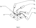
- Figure 4 illustrates that the tool approaches the crossing point of the cross beam sensor in four different orientations.
- the method for calibration includes four rounds.
- steps (a) through (f) are performed where the tool 21 assumes the first orientation O1 of the four different orientations O1, O2, O3 and O4 with respect to the cross beam sensor 1.
- a fifth posture of the industrial robot 20 is recorded from which, as mentioned above, the coordinates for the industrial robot wrist and the tool orientation can be calculated.
- the tool orientation is inherited from that was calculated in the first round and repeating steps (a), (b), (c), (d) and (f).
- a sixth, a seventh and an eighth posture of the industrial robot 20 are recorded respectively during the interruptions of the crossing point R of the first beam 14a and the second beam 14b of the cross beam sensor 1 by the tool centre point of the tool 21.
- the outputs from the computation for the four rounds have the fifth, sixth, seventh, and eighth postures of the industrial robot 20, and in consideration of them the tool centre point position of the tool 21 can be calculated by applying principle of four-point calibration.
- the tool 21 is fixed in the industrial robot cell and the cross beam sensor 1 is held by the industrial robot 20 (for example, attached to a wrist of the industrial robot).
- the tool calibration for scenario B is to identify the relative pose of the tool 21 with respect to a stationary point in the industrial robot cell.
- the industrial robot 20 needs to make relative movement between the tool 21 and the cross beam sensor 1 so that the tool center point of the tool 21 can approach the crossing point R of the cross beam sensor 1.
- step (a) the industrial robot 20 holds the cross beam sensor 1 and relatively move a first part 21a of the tool 21 and the cross beam sensor 1 with translational motion in an orientation O so that the first part 21a of the tool 21 respectively interrupts the first beam 14a and the second beam 14b of the cross beam sensor 1.
- the cross beam sensor 1 upon interruption of the first beam 14a, the cross beam sensor 1 sends a first signal to the industrial robot system 2 representing that the interruption of the first beam 14a occurs, and upon interruption of the second beam 14b, the cross beam sensor 1 sends a second signal to the industrial robot system 2 representing that the interruption of the second beam 14b occurs; the characteristic of translational movement renders the tool 21 retains the same orientation when it moves relatively to the cross beam sensor 1 and the first part 21 of the tool 21 interrupts the first beam 14a and the second beam 14b in the plane defined by the two beams.
- Step (b) records a first posture and a second posture of the industrial robot 20 during the interruptions of the first beam 14a and the second beam 14b of the cross beam sensor 1 by the first part 21a of the tool 21.
- the first posture of the industrial robot 20 from which the coordinates for any part of the industrial robot 20 can be calculated according to various coordinate system, for example the coordinates for representing the position of the industrial robot wrist with respect to the industrial robot base coordinate system/world coordinate system; the second posture of the industrial robot 20 is also recorded upon interruption of the second beam 14b by the first part 21a of the tool 21.
- the posture of the industrial robot 20 for the second part 21a of the tool 21 intersecting with the intersecting point R of the first beam 14a and the second beam 14b of the cross beam sensor 1 can be solved.
- the first beam direction D 1 and the second beam direction D 2 can be predetermined and represented with respect to the robot wrist coordinate system.
- this said posture of the industrial robot 20 is the coordinates of TCP0 representing the position of the industrial robot wrist 200 with respect to the industrial robot base coordinate system/world coordinate system and denoted as TCP0 1 .
- step (c) the industrial robot 20 holds the cross beam sensor 1 and relatively move a second part 21b of the tool 21 and the cross beam sensor 1 with translational motion in the same orientation O as used in step (a) so that the second part 21b of the tool 21 respectively interrupts the first beam 14a and the second beam 14b of the cross beam sensor 1.
- the cross beam sensor 1 upon interruption of the first beam 14a, the cross beam sensor 1 sends a third signal to the industrial robot system 2 representing that the interruption of the first beam 14a occurs, and upon interruption of the second beam 14b, the cross beam sensor 1 sends a fourth signal to the industrial robot system 2 representing that the interruption of the second beam 14b occurs; the characteristic of translational movement renders the tool 21 retains the same orientation as it moves relatively to the cross beam sensor 1 and the first part 21a of the tool 21 interrupts the first beam 14a and the second beam 14b in the plane defined by the two beams.
- Step (d) records a third posture and a fourth posture of the industrial robot 20 during the interruptions of the first beam 14a and the second beam 14b of the cross beam sensor 1 by the second part 21b of the tool 21.
- the first beam 14a upon the interruption of the first beam 14a, it records the third posture of the industrial robot 20 from which the coordinates for any part of the industrial robot 20 can be calculated according to various coordinate system by using known industrial robot kinematics, for example the coordinates for representing the position of the industrial robot wrist with respect to the industrial robot base coordinate system/world coordinate system; the fourth posture of the industrial robot 20 is also recorded upon interruption of the second beam 14b by the second part 21b of the tool 21.
- the posture of the industrial robot 20 for the second part 21b of the tool 21 intersecting with the intersecting point R of the first beam 14a and the second beam 14b of the cross beam sensor 1 can be solved.
- the first beam direction D 1 and the second beam direction D 2 can be represented with respect to the robot wrist coordinate system.
- this said posture of the industrial robot 20 is the coordinates of TCP0 representing the position of the industrial robot wrist 200 with respect to the industrial robot base coordinate system/world coordinate system and denoted as TCP0 2 .
- Step (e) calculates the tool orientation ⁇
- the tool orientation defined by the first part 21a and second part 21b is the same as the orientation defined by two TCP0 positions when the first part 21a and second part21b intersecting with intersecting point R respectively, wherein the first part 21a and the second part 21b of the tool 21 are separately disposed on a linear portion of the tool Therefore, the tool orientation can be calculated as follow:
- the orientation ⁇ of tool 21 is defined by the first part 21a and second part 21b, wherein the first part 21a and the second part 21b of the tool 21 are separately disposed on a linear portion of the tool 21 which is fixed in the industrial robot cell.
- the tool orientation ⁇ can be represented with respect to the industrial robot base coordinate system/world coordinate system.
- step (f) the industrial robot 20 holds the cross beam sensor 1 and relatively moves the tool 21 and the cross beam sensor 1 so that the tool centre point (TCP) of the tool 21 interrupts crossing point R of the first beam 14a and the second beam 14b of the cross beam sensor 1 in consideration of the tool orientation ⁇ and the posture of said TCP0 1 or TCP0 2 of the industrial robot 20.
- TCP tool centre point
- step (f) the industrial robot 20 holds the cross beam sensor 1 resuming the posture of said TCP0 1 or TCP0 2 and relatively move the tool 2 and the cross beam sensor 1 with translational motion in the same orientation O as used in step (a) with respect to the robot base coordinate/world coordinate system and in the direction of the tool orientation ⁇ with respect to the robot base coordinate/world coordinate system so that the tool centre point of said tool 21 interrupts the crossing point R of the cross beam sensor 1.
- said TCP of said tool 21 is the tip of said tool 21
- the ON/OFF status change of both said first signal and said second signal indicates whether the said TCP of said tool 21 is interrupting the crossing point R of the cross beam sensor 1.
- the industrial robot can guide the cross beam sensor to approach TCP of the tool.
- step (a) relatively moving a first part 21a of the tool 21 and a cross beam sensor 1 by the industrial robot 20 with translational motion in an orientation O so that the first part 21a of the tool 21 interrupts the first beam 14a of the cross beam sensor 1, moves along the first beam direction D 1 from the interruption point, and interrupts the second beam 14b of the cross beam sensor 1 at the crossing point R of the cross beam sensor 1.
- the industrial robot 20 holds the cross beam sensor 1 and moves the cross beam sensor 1 relatively to the tool 21.
- the cross beam sensor 1 Upon interruption of the first beam 14a, the cross beam sensor 1 sends a first signal to the industrial robot system 2 representing that the interruption of the first beam 14a occurs.
- the characteristic of translational movement renders the tool 21 retains the same orientation when it moves relatively to the cross beam sensor 1.
- step (b) the industrial robot system 2 records a second posture of the industrial robot 20 where the first part 21a of the tool 21 interrupts the second beam 14b of the cross beam sensor 1 at the crossing point R of the cross beam sensor 1.
- the cross beam sensor 1 sends a second signal to the industrial robot system 2 representing that the interruption of the second beam 14b occurs.
- the industrial robot system 2 records a second posture of the industrial robot 20 during the interruption of the second beam 14b of the cross beam sensor 1 by the first part 21a of the tool 21.
- step (c) relatively moving a second part 21b of the tool 21 and a cross beam sensor 1 by the industrial robot 20 with translational motion in the orientation O so that the second part 21b of the tool 21 interrupts the first/second beam 14a/14b of the cross beam sensor 1, moves along the first/second beam direction D 1 /D 2 from the interruption point, and interrupts the second/first beam 14b/14a of the cross beam sensor 1 at the crossing point R of the cross beam sensor 1.
- the industrial robot 20 holds the cross beam sensor 1 and moves the cross beam sensor 1 relatively to the tool 21.
- the cross beam sensor 1 Upon interruption of the first/second beam 14a/14b, the cross beam sensor 1 sends a third signal to the industrial robot 20 representing that the interruption of the first/second beam 14a/14b occurs.
- the characteristic of translational movement renders the tool 21 retains the same orientation when it moves relatively to the cross beam sensor 1.
- step (d) the industrial robot system 2 records a fourth posture of the industrial robot 20 where the second part 21b of the tool 21 interrupts the second/first beam 14b/14a of the cross beam sensor 1 at the crossing point R of the cross beam sensor 1.
- the cross beam sensor 1 sends a fourth signal to the industrial robot 20 representing that the interruption of the second/first beam 14b/14a occurs.
- the industrial robot system 2 records a fourth posture of the industrial robot 20 during the interruption of the second/first beam 14b/14a of the cross beam sensor 1 by the second part 21b of the tool 21.
- the second part 21b of the tool 21 interrupts crossing point R of the first beam 14a and the second beam 14b of the cross beam sensor 1 and the four posture of the industrial robot 20 becomes known.
- Step (e) calculates the tool orientation ⁇ in consideration of the second posture and the fourth posture of the industrial robot 20.
- the tool orientation defined by the first part 21a and second part 21b is the same as the orientation defined by two TCP0 positions, TCP0 1 and TCP0 2 when the first part 21a and the second part 21b intersecting with intersecting point R respectively, wherein the first part 21a and the second part 21b of the tool 21 are separately disposed on a linear portion of the tool.
- TCP0 1 is the second posture recorded of the industrial robot 20 in step (b).
- the coordinates for the industrial robot wrist can be calculated corresponding to the postures of the industrial robot 20.
- TCP0 2 is the fourth posture recorded of the industrial robot 20 in step (d).
- the coordinates for the industrial robot wrist can be calculated corresponding to the postures of the industrial robot 20.
- Step (f) relatively moves the tool 21 and the cross beam sensor 21 by the industrial robot 20 so that the tool centre point of the tool 21 interrupts the crossing point R of the cross beam sensor 1 in consideration of the tool orientation ⁇ and either the second posture or the fourth posture of the industrial robot 20.
- the method for calibration includes four rounds.
- steps (a) through (f) are performed where the tool 21 assumes the first orientation O1 of the four different orientations O1, O2, O3 and O4 with respect to the cross beam sensor 1.
- a fifth posture of the industrial robot 20 is recorded from which, as mentioned above, the coordinates for the industrial robot wrist and the tool orientation can be calculated.
- the tool orientation is inherited from that was calculated in the first round and repeating steps (a), (b), (c), (d) and (f).
- a sixth, a seventh and an eighth posture of the industrial robot 20 are recorded respectively during the interruptions of the crossing point R of the first beam 14a and the second beam 14b of the cross beam sensor 1 by the tool centre point of the tool 21.
- the outputs from the computation for the four rounds have the fifth, sixth, seventh, and eighth postures of the industrial robot 20, and in consideration of them the tool centre point position of the tool 21 can be calculated by applying principle of four-point.
- each of the first, second, third and fourth postures of the industrial robot 20 is determined by averaging the posture of the respective one at the instant of the interruption of the beam and that at the subsequent release of the beam.
- each of the first, second, third and fourth postures of the industrial robot 20 is determined by averaging the posture of the respective one at the instant of the interruption of the beam from one side and that from the opposite side.
- each of the first, second, third and fourth postures of the industrial robot 20 is determined by averaging the posture of the respective one at the instant of release of the beam from one side and that from the opposite side.
- the tool 21 is a linear-displacement sensor.
- the tool 21 is a linear-shaped fixture that is mounted on a peripheral of the industrial robot system 2.
Landscapes
- Engineering & Computer Science (AREA)
- Robotics (AREA)
- Mechanical Engineering (AREA)
- Manipulator (AREA)
Claims (12)
- Verfahren zum Kalibrieren eines Werkzeugmittelpunkts eines Werkzeugs (21) für ein Industrierobotersystem (2), umfassend einen Kreuzstrahlsensor (1), der einen ersten Strahl (14a) und einen zweiten Strahl (14b) hat, die gewinkelt zueinander stehen mit einem Scheitelwinkel größer als null und sich in einem Kreuzungspunkt (R) kreuzen, aufweisend:(a) Bewegen relativ zueinander eines ersten Teils (21a) des Werkzeugs und eines Kreuzstrahlsensors (1) durch den Industrieroboter (20) mit translatorischer Bewegung in einer Ausrichtung (O), sodass der erste Teil (21a) des Werkzeugs (21) jeweils den ersten Strahl (14a) und den zweiten Strahl (14b) des Kreuzstrahlsensors (1) unterbricht;(b) Aufzeichnen einer ersten Stellung und einer zweiten Stellung des Industrieroboters (20) während der Unterbrechungen des ersten Strahls (14a) und des zweiten Strahls (14b) des Kreuzstrahlsensors (1) durch den ersten Teil (21a) des Werkzeugs (21);(c) Bewegen relativ zueinander eines zweiten Teils (21b) des Werkzeugs (21) und des Kreuzstrahlsensors (1) durch den Industrieroboter (20) mit translatorischer Bewegung unter Beibehaltung der Ausrichtung (O), sodass der zweite Teil (21b) des Werkzeugs (21) den ersten Strahl (14a) bzw. den zweiten Strahl (14b) des Kreuzstrahlsensors (1) unterbricht;(d) Aufzeichnen einer dritten Stellung und einer vierten Stellung des Industrieroboters (20) während der Unterbrechungen des ersten Strahls (14a) und des zweiten Strahls (14b) des Kreuzstrahlsensors (1) durch den zweiten Teil (21b) des Werkzeugs (21);(e) Berechnen der Werkzeugausrichtung (Ω) unter Berücksichtigung der ersten Stellung, zweiten Stellung, dritten Stellung und vierten Stellung des Industrieroboters (20) sowie der Richtung des ersten Strahls (D1) und der Richtung des zweiten Strahls (D2); und(f) Bewegen relativ zueinander des Werkzeugs (21) und des Kreuzstrahlsensors (1) durch den Industrieroboter (20), sodass der Werkzeugmittelpunkt des Werkzeugs (21) unter Berücksichtigung der Werkzeugausrichtung (Ω) und entweder der ersten und der zweiten Stellung oder der dritten und der vierten Stellung des Industrieroboters (20) den Kreuzungspunkt (R) des Kreuzstrahlsensors (1) unterbricht.
- Verfahren zum Kalibrieren eines Werkzeugmittelpunkts eines Werkzeugs (21) für ein Industrierobotersystem (2), umfassend einen Kreuzstrahlsensor (1), der einen ersten Strahl (14a) und einen zweiten Strahl (14b) hat, die gewinkelt zueinander stehen mit einem Scheitelwinkel größer als null und sich in einem Kreuzungspunkt (R) kreuzen, wobei eine Richtung des ersten Strahls (D1) und eine Richtung des zweiten Strahls (D2) in Bezug auf eine Roboterbasis / ein Weltkoordinatensystem vorbestimmt sind, das Verfahren weist auf:(a) Bewegen relativ zueinander eines ersten Teils (21a) des Werkzeugs (21) und eines Kreuzstrahlsensors (1) durch den Industrieroboter (20) mit translatorischer Bewegung in einer Ausrichtung (O), sodass der erste Teil (21a) des Werkzeugs (21) den ersten Strahl (14a) des Kreuzstrahlsensors (1) unterbricht, sich vom Unterbrechungspunkt entlang der Richtung des ersten Strahls (D1) bewegt und den zweiten Strahl (14b) des Kreuzstrahlsensors (1) am Kreuzungspunkt (R) des Kreuzstrahlsensors (1) unterbricht;(b) Aufzeichnen einer zweiten Stellung des Industrieroboters (20), wobei der erste Teil (14a) des Werkzeugs (21) den zweiten Strahl (14b) des Kreuzstrahlsensors (1) an dem Kreuzungspunkt (R) des Kreuzstrahlsensors (1) unterbricht;(c) Bewegen relativ zueinander eines zweiten Teils des Werkzeugs (21) und des Kreuzstrahlsensors (1) durch den Industrieroboter (20) mit translatorischer Bewegung unter Beibehaltung der Ausrichtung (O), sodass der zweite Teil (21b) des Werkzeugs (21) den ersten (14a) / zweiten (14b) Strahl des Kreuzstrahlsensors (1) unterbricht, sich vom Unterbrechungspunkt entlang der Richtung des ersten (D1) / zweiten (D2) Strahls bewegt und den zweiten (14b) / ersten (14a) Strahl des Kreuzstrahlsensors (1) am Kreuzungspunkt (R) des Kreuzstrahlsensors (1) unterbricht;(d) Aufzeichnen einer vierten Stellung des Industrieroboters (20), wobei der zweite Teil (21b) des Werkzeugs (21) den zweiten Strahl (14b) des Kreuzstrahlsensors (1) an dem Kreuzungspunkt (R) des Kreuzstrahlsensors (1) unterbricht;(e) Berechnen der Werkzeugausrichtung (Ω) unter Berücksichtigung der zweiten Stellung und der vierten Stellung des Industrieroboters (20); und(f) Bewegen relativ zueinander des Werkzeugs (21) und des Kreuzstrahlsensors (1) durch den Industrieroboter (20), sodass der Werkzeugmittelpunkt des Werkzeugs (21) unter Berücksichtigung der Werkzeugausrichtung (Ω) und entweder der zweiten Stellung oder der vierten Stellung des Industrieroboters (20) den Kreuzungspunkt (R) des Kreuzstrahlsensors (1) unterbricht.
- Verfahren zum Kalibrieren eines Werkzeugmittelpunkts des Werkzeugs (21) für ein Industrierobotersystem (2), aufweisend:Durchführen des Verfahrens nach Anspruch 1 für eine erste Runde, bei der das Werkzeug (21) eine erste Ausrichtung von vier unterschiedlichen Ausrichtungen in Bezug auf den Kreuzstrahlsensor annimmt;Wiederholen des Verfahrens nach Anspruch 1 mit Ausnahme von Schritt (e) für eine zweite, eine dritte und eine vierte Runde, bei denen das Werkzeug (21) jeweils eine zweite, eine dritte und eine vierte Ausrichtung (O2, O3, O4) der vier unterschiedlichen Ausrichtungen in Bezug auf den Kreuzstrahlsensor (1) annimmt und in Bezug auf die zweite, die dritte und die vierte Runde die in Schritt (f) betrachtete Werkzeugausrichtung (Ω) die gleiche ist wie diejenige durch Schritt (e) berechnete;für jede der vier Runden, Aufzeichnen einer fünften, einer sechsten, einer siebten bzw. einer achten Stellung des Industrieroboters (20) jeweils während der Unterbrechungen des Kreuzungspunkts (R) des ersten Strahls (14a) und des zweiten Strahls (14b) des Kreuzstrahlsensors (1) durch den Werkzeugmittelpunkt des Werkzeugs (21); undBerechnen der Position des Werkzeugmittelpunkts unter Berücksichtigung der fünften, der sechsten, der siebten und der achten Position des Industrieroboters (20);wobei:das Werkzeug (21) am Handgelenk (200) des Industrieroboters (20) angebracht ist; undder Kreuzstrahlsensor (1) während der relativen Bewegung zwischen dem Kreuzstrahlsensor (1) und dem Werkzeug (21) in Bezug auf den Industrieroboter (20) fixiert ist.
- Verfahren zum Kalibrieren eines Werkzeugmittelpunkts des Werkzeugs (21) für ein Industrierobotersystem (2), aufweisend:Durchführen des Verfahrens nach Anspruch 1 für eine erste Runde, bei der das Werkzeug (21) eine erste Ausrichtung (O1) von vier unterschiedlichen Ausrichtungen (O1, O2, O3, O4) in Bezug auf den Kreuzstrahlsensor (1) annimmt;Wiederholen des Verfahrens nach Anspruch 1 mit Ausnahme von Schritt (e) für eine zweite, eine dritte und eine vierte Runde, bei denen das Werkzeug (21) jeweils eine zweite, eine dritte und eine vierte Ausrichtung (O2, O3, O4) der vier unterschiedlichen Ausrichtungen (O1, O2, O3, O4) in Bezug auf den Kreuzstrahlsensor (1) annimmt und in Bezug auf die zweite, die dritte und die vierte Runde die in Schritt (f) betrachtete Werkzeugausrichtung (Ω) die gleiche ist wie diejenige durch Schritt (e) berechnete;für jede der vier Runden, Aufzeichnen einer fünften, einer sechsten, einer siebten bzw. einer achten Stellung des Industrieroboters (20) jeweils während der Unterbrechungen des Kreuzungspunkts (R) des ersten Strahls (14a) und des zweiten Strahls (14b) des Kreuzstrahlsensors (1) durch den Werkzeugmittelpunkt des Werkzeugs (21); undBerechnen der Position des Werkzeugmittelpunkts unter Berücksichtigung der fünften, der sechsten, der siebten und der achten Position des Industrieroboters (20);wobei:der Kreuzstrahlsensor (1) am Handgelenk (200) des Industrieroboters (20) angebracht ist;das Werkzeug (21) während der relativen Bewegung zwischen dem Kreuzstrahlsensor (1) und dem Werkzeug (21) in Bezug auf den Industrieroboter (20) fixiert ist.
- Verfahren nach Anspruch 2, wobei:die Werkzeugausrichtung (Ω) in Bezug auf das Industrieroboter-Handgelenkkoordinatensystem dargestellt ist;die erste, zweite, dritte und vierte Stellung des Industrieroboters (20) in Bezug auf das Industrierobotersystem (2) dargestellt sind; unddie fünfte, sechste, siebte und achte Stellung des Industrieroboters (20) in Bezug auf das Industrierobotersystem (2) dargestellt sind.
- Verfahren nach Anspruch 3, wobei:die Werkzeugausrichtung (Ω) in Bezug auf das Industrieroboter-Koordinatensystem dargestellt ist;die erste, zweite, dritte und vier Stellung des Industrieroboters (20) in Bezug auf das Industrierobotersystem (2) dargestellt sind; unddie fünfte, sechste, siebte und achte Stellung des Industrieroboters (20) in Bezug auf das Industrierobotersystem (2) dargestellt sind.
- Verfahren nach Anspruch 1 oder 2 oder 3, wobei:
der erste Teil (21a) und der zweite Teil (21b) des Werkzeugs (21) getrennt auf einem linearen Abschnitt des Werkzeugs (21) angeordnet sind. - Verfahren nach Anspruch 1 oder 2 oder 3, wobei:
jede von der ersten, zweiten, dritten und vierten Stellung des Industrieroboters (20) bestimmt wird durch Mittelung der Stellung der jeweiligen zum Zeitpunkt der Unterbrechung des Strahls und derjenigen bei der anschließenden Freigabe des Strahls. - Verfahren nach Anspruch 1 oder 2 oder 3, wobei:
jede von der ersten, zweiten, dritten und vierten Stellung des Industrieroboters (20) bestimmt wird durch Mittelung der Stellung der jeweiligen zum Zeitpunkt der Unterbrechung des Strahls von einer Seite und derjenigen von der gegenüberliegenden Seite. - Verfahren nach Anspruch 1 oder 2 oder 3, wobei:
jede von der ersten, zweiten, dritten und vierten Stellung des Industrieroboters (20) bestimmt wird durch Mittelung der Stellung der jeweiligen zum Zeitpunkt der Freigabe des Strahls von einer Seite und derjenigen von der gegenüberliegenden Seite. - Verfahren nach Anspruch 1 oder 2 oder 3, wobei:
das Werkzeug (21) ein Linearwegsensor ist. - Verfahren nach Anspruch 1 oder 2 oder 3, wobei:
das Werkzeug (21) durch eine linearförmige Halterung ersetzt ist, die an einer Peripherie des Industrierobotersystems (2) angebracht ist.
Applications Claiming Priority (1)
| Application Number | Priority Date | Filing Date | Title |
|---|---|---|---|
| PCT/CN2014/076578 WO2015165062A1 (en) | 2014-04-30 | 2014-04-30 | Method for calibrating tool centre point for industrial robot system |
Publications (3)
| Publication Number | Publication Date |
|---|---|
| EP3137954A1 EP3137954A1 (de) | 2017-03-08 |
| EP3137954A4 EP3137954A4 (de) | 2018-03-28 |
| EP3137954B1 true EP3137954B1 (de) | 2019-08-28 |
Family
ID=54358021
Family Applications (1)
| Application Number | Title | Priority Date | Filing Date |
|---|---|---|---|
| EP14890545.8A Active EP3137954B1 (de) | 2014-04-30 | 2014-04-30 | Verfahren zur kalibrierung des werkzeugmittelpunkts für industrierobotersystem |
Country Status (5)
| Country | Link |
|---|---|
| US (1) | US10160116B2 (de) |
| EP (1) | EP3137954B1 (de) |
| CN (1) | CN106462140B (de) |
| ES (1) | ES2754039T3 (de) |
| WO (1) | WO2015165062A1 (de) |
Families Citing this family (20)
| Publication number | Priority date | Publication date | Assignee | Title |
|---|---|---|---|---|
| CN105844670B (zh) * | 2016-03-30 | 2018-12-18 | 广东速美达自动化股份有限公司 | 水平机器人移动相机多点移动标定方法 |
| JP6860843B2 (ja) * | 2017-02-20 | 2021-04-21 | 株式会社安川電機 | ロボットシステム、ロボット制御装置、及びロボット制御方法 |
| CN107053216A (zh) * | 2017-04-25 | 2017-08-18 | 苏州蓝斯视觉系统股份有限公司 | 机器人和末端执行器的自动标定方法及系统 |
| EP3421167A1 (de) | 2017-06-26 | 2019-01-02 | Fronius International GmbH | Verfahren und vorrichtung zur abtastung einer werkstückoberfläche eines metallischen werkstückes |
| CN107478183B (zh) * | 2017-07-31 | 2019-08-13 | 华中科技大学 | 基于多点姿态采样的串联型机器人运动学参数标定方法 |
| TWI668541B (zh) | 2017-09-29 | 2019-08-11 | 財團法人工業技術研究院 | 機器人工具中心點校正系統及其方法 |
| CN107511829B (zh) * | 2017-10-11 | 2020-06-05 | 深圳市威博特科技有限公司 | 机械手的控制方法及装置、可读存储介质及自动化设备 |
| CN109909999B (zh) * | 2017-12-13 | 2020-08-28 | 北京柏惠维康科技有限公司 | 一种获取机器人tcp坐标的方法和装置 |
| CN110614630B (zh) * | 2018-06-19 | 2022-10-18 | 台达电子工业股份有限公司 | 机械手臂的工具校正装置 |
| CN113365785B (zh) * | 2019-02-07 | 2025-09-16 | Abb瑞士股份有限公司 | 校准工业机器人的工具的方法、控制系统和工业机器人 |
| CN111716346B (zh) * | 2019-03-20 | 2021-09-17 | 台达电子工业股份有限公司 | 机械手臂工具校正方法及其校正装置 |
| US11820006B2 (en) | 2019-09-27 | 2023-11-21 | Abb Schweiz Ag | Apparatus and method for calibrating laser displacement sensor for use with robot |
| CN111421541B (zh) * | 2020-04-01 | 2022-04-08 | 无锡市创凯电气控制设备有限公司 | 一种tcp机器人工具末端3d、5d纠偏系统及其纠偏方法 |
| CN111844062B (zh) * | 2020-06-22 | 2022-03-29 | 东莞长盈精密技术有限公司 | 机加工标准化方法 |
| CN112428276B (zh) * | 2020-12-15 | 2023-10-13 | 常州信息职业技术学院 | 基于光电感应的工业机器人工具坐标系标定辅具及方法 |
| CN112549083B (zh) * | 2020-12-24 | 2023-10-13 | 常州信息职业技术学院 | 一种工业机器人工具坐标系标定装置及方法 |
| CN113442133B (zh) * | 2021-06-09 | 2024-09-10 | 配天机器人技术有限公司 | 机器人的工具中心点校准方法及校准系统、存储介质 |
| CN113715061B (zh) * | 2021-09-07 | 2024-04-19 | 南京信息职业技术学院 | 一种非接触式的工业机器人工具坐标标定工具及标定方法 |
| TWI837533B (zh) * | 2021-10-27 | 2024-04-01 | 財團法人工業技術研究院 | 十字雷射校正裝置及應用其之校正系統 |
| CN115890739B (zh) * | 2022-11-14 | 2025-07-01 | 佛山非夕机器人科技有限公司 | 用于机器人的工具中心点(tcp)标定工装 |
Family Cites Families (45)
| Publication number | Priority date | Publication date | Assignee | Title |
|---|---|---|---|---|
| US4969108A (en) * | 1988-04-08 | 1990-11-06 | Cincinnati Milacron Inc. | Vision seam tracking method and apparatus for a manipulator |
| US5457367A (en) * | 1993-08-06 | 1995-10-10 | Cycle Time Corporation | Tool center point calibration apparatus and method |
| JP3002097B2 (ja) * | 1994-08-25 | 2000-01-24 | ファナック株式会社 | ビジュアルトラッキング方法 |
| EP0812662B1 (de) * | 1995-12-27 | 2008-01-23 | Fanuc Ltd | Kompositdetektionssystem für roboter |
| US5910719A (en) * | 1996-09-17 | 1999-06-08 | Cycle Time Corporation | Tool center point calibration for spot welding guns |
| SE508228C2 (sv) * | 1997-05-07 | 1998-09-14 | Inst Verkstadstek Forsk Ivf | Anordning för detektering och beräkning av en laserstråles fokusläge, form och effektfördelning |
| US6044308A (en) * | 1997-06-13 | 2000-03-28 | Huissoon; Jan Paul | Method and device for robot tool frame calibration |
| WO2000025185A1 (en) * | 1998-10-27 | 2000-05-04 | Irobotics, Inc. | Robotic process planning using templates |
| SE9804450D0 (sv) * | 1998-12-17 | 1998-12-17 | Robotkonsult Ab | Metod och anordningar för automatisk in-line kalibrering av robot, verktyg och cell |
| WO2001000370A1 (de) * | 1999-06-26 | 2001-01-04 | Kuka Schweissanlagen Gmbh | Verfahren und vorrichtung zum kalibrieren von robotermessstationen, manipulatoren und mitgeführten optischen messeinrichtungen |
| US6430472B1 (en) * | 1999-12-20 | 2002-08-06 | Servo-Robot Inc. | Robot feature tracking devices and methods |
| US6434449B1 (en) * | 2000-08-03 | 2002-08-13 | Pierre De Smet | Method and device for automated robot-cell calibration |
| GB0130986D0 (en) * | 2001-12-27 | 2002-02-13 | Prophet Control Systems Ltd | Programming robots with offline design |
| DE10305384A1 (de) * | 2003-02-11 | 2004-08-26 | Kuka Roboter Gmbh | Verfahren und Vorrichtung zur Visualisierung rechnergestützter Informationen |
| JP4501103B2 (ja) * | 2003-10-17 | 2010-07-14 | 株式会社安川電機 | 半導体ウェハ搬送ロボットのキャリブレーション方法およびそれを備えた半導体ウェハ搬送ロボット、ウェハ搬送装置 |
| JP3733364B2 (ja) * | 2003-11-18 | 2006-01-11 | ファナック株式会社 | 教示位置修正方法 |
| DE102004010312B8 (de) * | 2004-03-03 | 2009-07-30 | Advintec Gmbh | Verfahren zum Einmessen eines Arbeitspunktes |
| JP4191080B2 (ja) * | 2004-04-07 | 2008-12-03 | ファナック株式会社 | 計測装置 |
| JP3946711B2 (ja) * | 2004-06-02 | 2007-07-18 | ファナック株式会社 | ロボットシステム |
| WO2006055770A2 (en) | 2004-11-19 | 2006-05-26 | Dynalog, Inc. | Robot cell calibration |
| WO2006079617A1 (en) * | 2005-01-26 | 2006-08-03 | Abb Ab | Device and method for calibrating the center point of a tool mounted on a robot by means of a camera |
| DE102007020604A1 (de) * | 2007-05-02 | 2008-11-06 | Wiest Ag | Vorrichtung und Verfahren zur berührungslosen Positionsbestimmung |
| US8655429B2 (en) * | 2007-06-29 | 2014-02-18 | Accuray Incorporated | Robotic arm for a radiation treatment system |
| WO2009059323A1 (en) * | 2007-11-01 | 2009-05-07 | Rimrock Automation, Inc. Dba Wolf Robotics | A method and system for finding a tool center point for a robot using an external camera |
| EP2062674B1 (de) * | 2007-11-20 | 2016-11-02 | TRUMPF Werkzeugmaschinen GmbH + Co. KG | Verfahren zum Vorbereiten und zum Durchführen eines Laserschweissprozesses |
| AU2009226028B2 (en) * | 2008-03-21 | 2013-11-14 | Variation Reduction Solutions, Inc. | External system for robotic accuracy enhancement |
| ES2412393T3 (es) * | 2008-06-09 | 2013-07-11 | Abb Technology Ltd | Un método y un sistema para facilitar la calibración de una célula robótica programada fuera de línea |
| US8180487B1 (en) * | 2008-09-30 | 2012-05-15 | Western Digital Technologies, Inc. | Calibrated vision based robotic system |
| US8406922B2 (en) * | 2009-07-31 | 2013-03-26 | Fanuc Robotics America, Inc. | System and method for setting the tool center point of a robotic tool |
| JP4763074B2 (ja) * | 2009-08-03 | 2011-08-31 | ファナック株式会社 | ロボットのツール先端点の位置の計測装置および計測方法 |
| US9669546B2 (en) * | 2011-03-14 | 2017-06-06 | Matthew E. Trompeter | Robotic work object cell calibration method |
| US20150306769A1 (en) * | 2011-03-14 | 2015-10-29 | Matthew E. Trompeter | Calibration for robotic systems |
| US9266241B2 (en) | 2011-03-14 | 2016-02-23 | Matthew E. Trompeter | Robotic work object cell calibration system |
| WO2012156071A1 (en) * | 2011-05-13 | 2012-11-22 | Precitec Kg | Laser material processing system with at least one inertial sensor corresponding laser processing method |
| CN102909728B (zh) * | 2011-08-05 | 2015-11-25 | 鸿富锦精密工业(深圳)有限公司 | 机器人工具中心点的视觉校正方法 |
| CN103101060B (zh) * | 2011-11-11 | 2015-07-01 | 鸿富锦精密工业(深圳)有限公司 | 机器人工具中心点的传感校正方法 |
| US9713869B2 (en) * | 2012-03-07 | 2017-07-25 | Matthew E. Trompeter | Calibration of robot work paths |
| US8485017B1 (en) * | 2012-08-01 | 2013-07-16 | Matthew E. Trompeter | Robotic work object cell calibration system |
| US20140365006A1 (en) * | 2013-06-07 | 2014-12-11 | Matthew E. Trompeter | Visual Datum Reference Tool |
| US9114534B2 (en) * | 2013-01-14 | 2015-08-25 | Matthew E Trompeter | Robot calibration systems |
| CN103115629A (zh) * | 2013-01-23 | 2013-05-22 | 天津大学 | 机器人柔性视觉测量系统中工具坐标系快速修复方法 |
| DE102013008645B3 (de) * | 2013-05-21 | 2014-08-21 | Alsitec S.A.R.L. | Bearbeitungskopf für eine Laserbearbeitungsvorrichtung, Laserbearbeitungsvorrichtung sowie Verfahren zum Messen von Veränderungen der Brennweite einer in einem Bearbeitungskopf enthaltenen Fokussieroptik |
| US20140365007A1 (en) * | 2013-06-07 | 2014-12-11 | Matthew E. Trompeter | Visual Datum Reference Tool |
| EP2878920A1 (de) * | 2013-11-28 | 2015-06-03 | Hexagon Technology Center GmbH | Kalibrierung einer Koordinatenmessmaschine mithilfe eines Kalibrierungslaserkopfs am Werkzeugmittelspunkt |
| JP6555248B2 (ja) * | 2014-02-28 | 2019-08-07 | ソニー株式会社 | 医療用アーム装置、キャリブレーション方法及びプログラム |
-
2014
- 2014-04-30 EP EP14890545.8A patent/EP3137954B1/de active Active
- 2014-04-30 ES ES14890545T patent/ES2754039T3/es active Active
- 2014-04-30 CN CN201480077815.8A patent/CN106462140B/zh active Active
- 2014-04-30 WO PCT/CN2014/076578 patent/WO2015165062A1/en not_active Ceased
-
2016
- 2016-08-30 US US15/251,366 patent/US10160116B2/en active Active
Non-Patent Citations (1)
| Title |
|---|
| None * |
Also Published As
| Publication number | Publication date |
|---|---|
| US20160368147A1 (en) | 2016-12-22 |
| US10160116B2 (en) | 2018-12-25 |
| EP3137954A4 (de) | 2018-03-28 |
| EP3137954A1 (de) | 2017-03-08 |
| CN106462140B (zh) | 2019-04-26 |
| CN106462140A (zh) | 2017-02-22 |
| ES2754039T3 (es) | 2020-04-15 |
| WO2015165062A1 (en) | 2015-11-05 |
Similar Documents
| Publication | Publication Date | Title |
|---|---|---|
| US10160116B2 (en) | Method for calibrating tool centre point for industrial robot system | |
| EP3433061B1 (de) | Automatisches kalibrierverfahren für ein robotersystem und entsprechendes robotersystem | |
| EP2981397B1 (de) | Robotersystem und verfahren zur kalibrierung | |
| CN102458779B (zh) | 机械手校正装置及其方法 | |
| CN112025772B (zh) | 一种基于视觉测量的机械臂自主标定方法 | |
| CN108748159B (zh) | 一种机械臂工具坐标系自标定方法 | |
| US20190176325A1 (en) | An Error Modeling Method For End-Effector Space-Curve Trajectory Of Six Degree-of-Freedom Robots | |
| Zhenhua et al. | A distance error based industrial robot kinematic calibration method | |
| US9114534B2 (en) | Robot calibration systems | |
| US20200254625A1 (en) | Through-beam auto teaching | |
| CN104476549A (zh) | 基于视觉测量的机械臂运动路径补偿方法 | |
| Kirschner et al. | Notion on the correct use of the robot effective mass in the safety context and comments on ISO/TS 15066 | |
| US9713869B2 (en) | Calibration of robot work paths | |
| US20140365006A1 (en) | Visual Datum Reference Tool | |
| CN108908344A (zh) | 一种巡检机器人机械臂末端空间定位方法 | |
| US20140365007A1 (en) | Visual Datum Reference Tool | |
| JP2011011326A (ja) | ロボットのツール位置較正治具と方法 | |
| KR102658278B1 (ko) | 이동형 로봇 및 그것의 로봇 암 정렬 방법 | |
| KR102262235B1 (ko) | Olp에서 생성된 실제로봇 작업프로그램의 보정방법 | |
| US10800041B2 (en) | Absolute position determination of a robotic device and robotic device | |
| Zhang et al. | An error compensation method for on-machine measuring blade with industrial robot | |
| CN115091465A (zh) | 机械臂路径补偿方法、装置、电子设备及存储介质 | |
| Tang et al. | Eye-in-finger: Smart fingers for delicate assembly and disassembly of lego | |
| Andreff et al. | Vision‐based kinematic calibration of an H4 parallel mechanism: practical accuracies | |
| Marvel et al. | Tools for robotics in sme workcells: challenges and approaches for calibration and registration |
Legal Events
| Date | Code | Title | Description |
|---|---|---|---|
| PUAI | Public reference made under article 153(3) epc to a published international application that has entered the european phase |
Free format text: ORIGINAL CODE: 0009012 |
|
| STAA | Information on the status of an ep patent application or granted ep patent |
Free format text: STATUS: REQUEST FOR EXAMINATION WAS MADE |
|
| 17P | Request for examination filed |
Effective date: 20160823 |
|
| AK | Designated contracting states |
Kind code of ref document: A1 Designated state(s): AL AT BE BG CH CY CZ DE DK EE ES FI FR GB GR HR HU IE IS IT LI LT LU LV MC MK MT NL NO PL PT RO RS SE SI SK SM TR |
|
| AX | Request for extension of the european patent |
Extension state: BA ME |
|
| DAX | Request for extension of the european patent (deleted) | ||
| A4 | Supplementary search report drawn up and despatched |
Effective date: 20180226 |
|
| RIC1 | Information provided on ipc code assigned before grant |
Ipc: G05B 19/402 20060101AFI20180220BHEP |
|
| GRAP | Despatch of communication of intention to grant a patent |
Free format text: ORIGINAL CODE: EPIDOSNIGR1 |
|
| STAA | Information on the status of an ep patent application or granted ep patent |
Free format text: STATUS: GRANT OF PATENT IS INTENDED |
|
| INTG | Intention to grant announced |
Effective date: 20190402 |
|
| GRAS | Grant fee paid |
Free format text: ORIGINAL CODE: EPIDOSNIGR3 |
|
| GRAA | (expected) grant |
Free format text: ORIGINAL CODE: 0009210 |
|
| STAA | Information on the status of an ep patent application or granted ep patent |
Free format text: STATUS: THE PATENT HAS BEEN GRANTED |
|
| AK | Designated contracting states |
Kind code of ref document: B1 Designated state(s): AL AT BE BG CH CY CZ DE DK EE ES FI FR GB GR HR HU IE IS IT LI LT LU LV MC MK MT NL NO PL PT RO RS SE SI SK SM TR |
|
| REG | Reference to a national code |
Ref country code: GB Ref legal event code: FG4D |
|
| REG | Reference to a national code |
Ref country code: CH Ref legal event code: EP |
|
| REG | Reference to a national code |
Ref country code: DE Ref legal event code: R096 Ref document number: 602014052758 Country of ref document: DE |
|
| REG | Reference to a national code |
Ref country code: AT Ref legal event code: REF Ref document number: 1173170 Country of ref document: AT Kind code of ref document: T Effective date: 20190915 |
|
| REG | Reference to a national code |
Ref country code: IE Ref legal event code: FG4D |
|
| REG | Reference to a national code |
Ref country code: NL Ref legal event code: MP Effective date: 20190828 |
|
| REG | Reference to a national code |
Ref country code: LT Ref legal event code: MG4D |
|
| PG25 | Lapsed in a contracting state [announced via postgrant information from national office to epo] |
Ref country code: FI Free format text: LAPSE BECAUSE OF FAILURE TO SUBMIT A TRANSLATION OF THE DESCRIPTION OR TO PAY THE FEE WITHIN THE PRESCRIBED TIME-LIMIT Effective date: 20190828 Ref country code: PT Free format text: LAPSE BECAUSE OF FAILURE TO SUBMIT A TRANSLATION OF THE DESCRIPTION OR TO PAY THE FEE WITHIN THE PRESCRIBED TIME-LIMIT Effective date: 20191230 Ref country code: NL Free format text: LAPSE BECAUSE OF FAILURE TO SUBMIT A TRANSLATION OF THE DESCRIPTION OR TO PAY THE FEE WITHIN THE PRESCRIBED TIME-LIMIT Effective date: 20190828 Ref country code: SE Free format text: LAPSE BECAUSE OF FAILURE TO SUBMIT A TRANSLATION OF THE DESCRIPTION OR TO PAY THE FEE WITHIN THE PRESCRIBED TIME-LIMIT Effective date: 20190828 Ref country code: BG Free format text: LAPSE BECAUSE OF FAILURE TO SUBMIT A TRANSLATION OF THE DESCRIPTION OR TO PAY THE FEE WITHIN THE PRESCRIBED TIME-LIMIT Effective date: 20191128 Ref country code: LT Free format text: LAPSE BECAUSE OF FAILURE TO SUBMIT A TRANSLATION OF THE DESCRIPTION OR TO PAY THE FEE WITHIN THE PRESCRIBED TIME-LIMIT Effective date: 20190828 Ref country code: NO Free format text: LAPSE BECAUSE OF FAILURE TO SUBMIT A TRANSLATION OF THE DESCRIPTION OR TO PAY THE FEE WITHIN THE PRESCRIBED TIME-LIMIT Effective date: 20191128 Ref country code: HR Free format text: LAPSE BECAUSE OF FAILURE TO SUBMIT A TRANSLATION OF THE DESCRIPTION OR TO PAY THE FEE WITHIN THE PRESCRIBED TIME-LIMIT Effective date: 20190828 |
|
| PG25 | Lapsed in a contracting state [announced via postgrant information from national office to epo] |
Ref country code: GR Free format text: LAPSE BECAUSE OF FAILURE TO SUBMIT A TRANSLATION OF THE DESCRIPTION OR TO PAY THE FEE WITHIN THE PRESCRIBED TIME-LIMIT Effective date: 20191129 Ref country code: RS Free format text: LAPSE BECAUSE OF FAILURE TO SUBMIT A TRANSLATION OF THE DESCRIPTION OR TO PAY THE FEE WITHIN THE PRESCRIBED TIME-LIMIT Effective date: 20190828 Ref country code: IS Free format text: LAPSE BECAUSE OF FAILURE TO SUBMIT A TRANSLATION OF THE DESCRIPTION OR TO PAY THE FEE WITHIN THE PRESCRIBED TIME-LIMIT Effective date: 20191228 Ref country code: AL Free format text: LAPSE BECAUSE OF FAILURE TO SUBMIT A TRANSLATION OF THE DESCRIPTION OR TO PAY THE FEE WITHIN THE PRESCRIBED TIME-LIMIT Effective date: 20190828 Ref country code: LV Free format text: LAPSE BECAUSE OF FAILURE TO SUBMIT A TRANSLATION OF THE DESCRIPTION OR TO PAY THE FEE WITHIN THE PRESCRIBED TIME-LIMIT Effective date: 20190828 |
|
| REG | Reference to a national code |
Ref country code: AT Ref legal event code: MK05 Ref document number: 1173170 Country of ref document: AT Kind code of ref document: T Effective date: 20190828 |
|
| PG25 | Lapsed in a contracting state [announced via postgrant information from national office to epo] |
Ref country code: TR Free format text: LAPSE BECAUSE OF FAILURE TO SUBMIT A TRANSLATION OF THE DESCRIPTION OR TO PAY THE FEE WITHIN THE PRESCRIBED TIME-LIMIT Effective date: 20190828 |
|
| REG | Reference to a national code |
Ref country code: ES Ref legal event code: FG2A Ref document number: 2754039 Country of ref document: ES Kind code of ref document: T3 Effective date: 20200415 |
|
| PG25 | Lapsed in a contracting state [announced via postgrant information from national office to epo] |
Ref country code: EE Free format text: LAPSE BECAUSE OF FAILURE TO SUBMIT A TRANSLATION OF THE DESCRIPTION OR TO PAY THE FEE WITHIN THE PRESCRIBED TIME-LIMIT Effective date: 20190828 Ref country code: DK Free format text: LAPSE BECAUSE OF FAILURE TO SUBMIT A TRANSLATION OF THE DESCRIPTION OR TO PAY THE FEE WITHIN THE PRESCRIBED TIME-LIMIT Effective date: 20190828 Ref country code: AT Free format text: LAPSE BECAUSE OF FAILURE TO SUBMIT A TRANSLATION OF THE DESCRIPTION OR TO PAY THE FEE WITHIN THE PRESCRIBED TIME-LIMIT Effective date: 20190828 Ref country code: PL Free format text: LAPSE BECAUSE OF FAILURE TO SUBMIT A TRANSLATION OF THE DESCRIPTION OR TO PAY THE FEE WITHIN THE PRESCRIBED TIME-LIMIT Effective date: 20190828 Ref country code: RO Free format text: LAPSE BECAUSE OF FAILURE TO SUBMIT A TRANSLATION OF THE DESCRIPTION OR TO PAY THE FEE WITHIN THE PRESCRIBED TIME-LIMIT Effective date: 20190828 |
|
| PG25 | Lapsed in a contracting state [announced via postgrant information from national office to epo] |
Ref country code: CZ Free format text: LAPSE BECAUSE OF FAILURE TO SUBMIT A TRANSLATION OF THE DESCRIPTION OR TO PAY THE FEE WITHIN THE PRESCRIBED TIME-LIMIT Effective date: 20190828 Ref country code: SK Free format text: LAPSE BECAUSE OF FAILURE TO SUBMIT A TRANSLATION OF THE DESCRIPTION OR TO PAY THE FEE WITHIN THE PRESCRIBED TIME-LIMIT Effective date: 20190828 Ref country code: IS Free format text: LAPSE BECAUSE OF FAILURE TO SUBMIT A TRANSLATION OF THE DESCRIPTION OR TO PAY THE FEE WITHIN THE PRESCRIBED TIME-LIMIT Effective date: 20200224 Ref country code: SM Free format text: LAPSE BECAUSE OF FAILURE TO SUBMIT A TRANSLATION OF THE DESCRIPTION OR TO PAY THE FEE WITHIN THE PRESCRIBED TIME-LIMIT Effective date: 20190828 |
|
| REG | Reference to a national code |
Ref country code: DE Ref legal event code: R097 Ref document number: 602014052758 Country of ref document: DE |
|
| PLBE | No opposition filed within time limit |
Free format text: ORIGINAL CODE: 0009261 |
|
| STAA | Information on the status of an ep patent application or granted ep patent |
Free format text: STATUS: NO OPPOSITION FILED WITHIN TIME LIMIT |
|
| PG2D | Information on lapse in contracting state deleted |
Ref country code: IS |
|
| 26N | No opposition filed |
Effective date: 20200603 |
|
| PG25 | Lapsed in a contracting state [announced via postgrant information from national office to epo] |
Ref country code: SI Free format text: LAPSE BECAUSE OF FAILURE TO SUBMIT A TRANSLATION OF THE DESCRIPTION OR TO PAY THE FEE WITHIN THE PRESCRIBED TIME-LIMIT Effective date: 20190828 |
|
| PG25 | Lapsed in a contracting state [announced via postgrant information from national office to epo] |
Ref country code: MC Free format text: LAPSE BECAUSE OF FAILURE TO SUBMIT A TRANSLATION OF THE DESCRIPTION OR TO PAY THE FEE WITHIN THE PRESCRIBED TIME-LIMIT Effective date: 20190828 |
|
| REG | Reference to a national code |
Ref country code: CH Ref legal event code: PL |
|
| PG25 | Lapsed in a contracting state [announced via postgrant information from national office to epo] |
Ref country code: LU Free format text: LAPSE BECAUSE OF NON-PAYMENT OF DUE FEES Effective date: 20200430 Ref country code: LI Free format text: LAPSE BECAUSE OF NON-PAYMENT OF DUE FEES Effective date: 20200430 Ref country code: CH Free format text: LAPSE BECAUSE OF NON-PAYMENT OF DUE FEES Effective date: 20200430 |
|
| REG | Reference to a national code |
Ref country code: BE Ref legal event code: MM Effective date: 20200430 |
|
| PG25 | Lapsed in a contracting state [announced via postgrant information from national office to epo] |
Ref country code: BE Free format text: LAPSE BECAUSE OF NON-PAYMENT OF DUE FEES Effective date: 20200430 |
|
| GBPC | Gb: european patent ceased through non-payment of renewal fee |
Effective date: 20200430 |
|
| PG25 | Lapsed in a contracting state [announced via postgrant information from national office to epo] |
Ref country code: IE Free format text: LAPSE BECAUSE OF NON-PAYMENT OF DUE FEES Effective date: 20200430 Ref country code: GB Free format text: LAPSE BECAUSE OF NON-PAYMENT OF DUE FEES Effective date: 20200430 |
|
| PG25 | Lapsed in a contracting state [announced via postgrant information from national office to epo] |
Ref country code: MT Free format text: LAPSE BECAUSE OF FAILURE TO SUBMIT A TRANSLATION OF THE DESCRIPTION OR TO PAY THE FEE WITHIN THE PRESCRIBED TIME-LIMIT Effective date: 20190828 Ref country code: CY Free format text: LAPSE BECAUSE OF FAILURE TO SUBMIT A TRANSLATION OF THE DESCRIPTION OR TO PAY THE FEE WITHIN THE PRESCRIBED TIME-LIMIT Effective date: 20190828 |
|
| PG25 | Lapsed in a contracting state [announced via postgrant information from national office to epo] |
Ref country code: MK Free format text: LAPSE BECAUSE OF FAILURE TO SUBMIT A TRANSLATION OF THE DESCRIPTION OR TO PAY THE FEE WITHIN THE PRESCRIBED TIME-LIMIT Effective date: 20190828 |
|
| PGFP | Annual fee paid to national office [announced via postgrant information from national office to epo] |
Ref country code: ES Payment date: 20260529 Year of fee payment: 13 |
|
| PGFP | Annual fee paid to national office [announced via postgrant information from national office to epo] |
Ref country code: IT Payment date: 20260427 Year of fee payment: 13 |
|
| PGFP | Annual fee paid to national office [announced via postgrant information from national office to epo] |
Ref country code: DE Payment date: 20260422 Year of fee payment: 13 |
|
| PGFP | Annual fee paid to national office [announced via postgrant information from national office to epo] |
Ref country code: FR Payment date: 20260420 Year of fee payment: 13 |