EP3138528B1 - Boîtier allongé à usage médical et colonnes associées - Google Patents
Boîtier allongé à usage médical et colonnes associées Download PDFInfo
- Publication number
- EP3138528B1 EP3138528B1 EP14890932.8A EP14890932A EP3138528B1 EP 3138528 B1 EP3138528 B1 EP 3138528B1 EP 14890932 A EP14890932 A EP 14890932A EP 3138528 B1 EP3138528 B1 EP 3138528B1
- Authority
- EP
- European Patent Office
- Prior art keywords
- box body
- insulator
- medical pendant
- pendant box
- medical
- Prior art date
- Legal status (The legal status is an assumption and is not a legal conclusion. Google has not performed a legal analysis and makes no representation as to the accuracy of the status listed.)
- Active
Links
Images


Classifications
-
- H—ELECTRICITY
- H02—GENERATION; CONVERSION OR DISTRIBUTION OF ELECTRIC POWER
- H02G—INSTALLATION OF ELECTRIC CABLES OR LINES, OR OF COMBINED OPTICAL AND ELECTRIC CABLES OR LINES
- H02G3/00—Installations of electric cables or lines or protective tubing therefor in or on buildings, equivalent structures or vehicles
- H02G3/02—Details
- H02G3/04—Protective tubing or conduits, e.g. cable ladders or cable troughs
- H02G3/0493—Service poles
-
- A—HUMAN NECESSITIES
- A61—MEDICAL OR VETERINARY SCIENCE; HYGIENE
- A61B—DIAGNOSIS; SURGERY; IDENTIFICATION
- A61B90/00—Instruments, implements or accessories specially adapted for surgery or diagnosis and not covered by any of the groups A61B1/00 - A61B50/00, e.g. for luxation treatment or for protecting wound edges
- A61B90/08—Accessories or related features not otherwise provided for
-
- A—HUMAN NECESSITIES
- A61—MEDICAL OR VETERINARY SCIENCE; HYGIENE
- A61B—DIAGNOSIS; SURGERY; IDENTIFICATION
- A61B90/00—Instruments, implements or accessories specially adapted for surgery or diagnosis and not covered by any of the groups A61B1/00 - A61B50/00, e.g. for luxation treatment or for protecting wound edges
-
- A—HUMAN NECESSITIES
- A61—MEDICAL OR VETERINARY SCIENCE; HYGIENE
- A61G—TRANSPORT, PERSONAL CONVEYANCES, OR ACCOMMODATION SPECIALLY ADAPTED FOR PATIENTS OR DISABLED PERSONS; OPERATING TABLES OR CHAIRS; CHAIRS FOR DENTISTRY; FUNERAL DEVICES
- A61G12/00—Accommodation for nursing, e.g. in hospitals, not covered by groups A61G1/00 - A61G11/00, e.g. trolleys for transport of medicaments or food; Prescription lists
- A61G12/002—Supply appliances, e.g. columns for gas, fluid, electricity supply
-
- H—ELECTRICITY
- H01—ELECTRIC ELEMENTS
- H01R—ELECTRICALLY-CONDUCTIVE CONNECTIONS; STRUCTURAL ASSOCIATIONS OF A PLURALITY OF MUTUALLY-INSULATED ELECTRICAL CONNECTING ELEMENTS; COUPLING DEVICES; CURRENT COLLECTORS
- H01R25/00—Coupling parts adapted for simultaneous co-operation with two or more identical counterparts, e.g. for distributing energy to two or more circuits
- H01R25/14—Rails or bus-bars constructed so that the counterparts can be connected thereto at any point along their length
Definitions
- the present invention relates to the technical field of medical equipment, and more particularly to a medical pendant box body and posts used for the medical pendant box body.
- Medical pendant is an indispensable medical equipment used in modern hospital operating room, intensive care unit and the like, and various accessories such as handle, laminate and the like are often needed to be fixed (installed) to the medical pendant so as to achieve various functions.
- the main structure of a medical pendant is a box body. Therefore, in order to achieve the mechanical connection and electrical connection to various medical accessories, various mechanical interfaces and electrical interfaces are needed to be set on the medical pendant box body.
- European patent application EP 2 058 911 A1 is directed to a medical pendant box comprising a coupling rail, which extends along a rectangular, elongated carrier.
- the coupling rail includes two electrically insulated conductor rails e.g. power supply conductor rail and data transfer conductor rail, which continuously run in the coupling rail.
- the coupling rail is designed as a hollow rail with an opening along a longitudinal direction.
- the conductor rails are arranged on an inner side of the hollow rail.
- a covering device i.e. lip, made of flexible material is provided along the opening, where the covering rail narrows or closes the opening.
- One of the purposes of the present invention is to overcome the above-mentioned disadvantages of the existing medical pendant box body, there is provided a medical pendant box body which can have standardised interfaces, without complicatedly connecting electrical cables, being easy for disassembly and assembly, and the position of a medical accessory capable of being freely adjusted.
- a medical pendant box body comprises at least two panels, at least two posts extending along the longitudinal direction of the medical pendant box body, an upper base plate and a lower base plate, the at least two panels are respectively fixed to the at least two posts, the upper base plate and the lower base plate are respectively fixed to the upper edge and the lower edge of each panel of the at least two panels, at least one post of the at least two posts is provided with an electrical interface, the electrical interface comprises only one inner groove located at the front surface of the post and extending along the longitudinal direction of the post, an insulator accommodated within the inner groove, and a conductor sealed within the insulator.
- the medical pendant box body of the present invention can have the following advantageous technical effects: a standardised interface can be provided, it is not necessary to connect electrical cables in a complicated manner, disassembly is easy and the position of a medical accessory can be freely adjusted.
- the inner groove is substantially filled when the insulator is accommodated within the inner groove and the conductor is sealed within the insulator.
- the medical pendant box body of the present invention can have the following advantageous technical effects: the electrical interface has good reliability and insulation performance, effectively prevents the infiltration of water or other cleaning agents during the cleaning process in a hospital.
- the number of the insulators within the inner groove is two, and one conductor is sealed within each insulator.
- the medical pendant box body of the present invention can have the following advantageous technical effects: by means of the appropriate number and settings of the above insulators and conductors, the simple and reliable connection between the plug of the electrical accessory and the conductor inside the post can be achieved.
- the cross section of the conductors is substantially Y-shaped or ⁇ -shaped.
- the medical pendant box body of the present invention can have the following advantageous technical effects: by means of the appropriate shape of the above conductors, the simpler and reliable connection between the plug of the electrical accessory and the conductor inside the post can be achieved.
- the insulator comprises an insulator front part and an insulator rear part, the conductor is sealed within the insulator rear part, the insulator front part has a substantially flat front surface and a gap extending along the longitudinal direction of the medical pendant box body.
- the medical pendant box body of the present invention can have the following advantageous technical effects: the gap can be provided for inserting the plug of the electrical accessory, which facilitates the simpler and reliable connection between the plug of the electrical accessory and the conductor inside the post.
- the width size of the gap and the elasticity of the insulator front part are designed so that the gap can be provided for inserting the plug of an electrical accessory and the insulator front part is substantially sealed before inserting the plug.
- the medical pendant box body of the present invention can have the following advantageous technical effects: the simpler and reliable connection between the plug of the electrical accessory and the conductor inside the post is achieved, meanwhile effectively preventing the infiltration of water or other cleaning agents during the cleaning process in a hospital.
- the width size of the inner groove and the elasticity of the insulator are designed to make the insulator produce necessary predeformation so as to produce certain pre-pressure, so that when the plug of an electrical accessory is inserted into the electrical interface to connect to the conductor, the pre-pressure prevents the plug from disengaging from the conductor.
- the medical pendant box body of the present invention can have the following advantageous technical effects: the reliability of the connection between the plug of the electrical accessory and the conductor is improved, and the disengagement of the plug from the conductor is effectively prevented.
- the conductor is connected to the control board of the medical pendant via a connector.
- the medical pendant box body of the present invention can have the following advantageous technical effect: multiple functions such as air brake control, electromagnetic brake control, motor control, direct current supply, video or audio signal supply and the like can be accomplished by means of the control board.
- At least one post of the at least two posts is also provided with a mechanical interface, the mechanical interface comprising a concave curved portion or a convex curved portion for matching to the convex curved portion or the concave curved portion of a mechanical connecting piece.
- the medical pendant box body of the present invention can have the following advantageous technical effects: by means of the same post in the medical pendant box body, both the mechanical connection and the electrical connection can be achieved, the number of the components needed is reduced, and the connection reliability is improved; furthermore, a medical accessory is easy to be disassembled and assembled, and the position of the medical accessory can be freely and steplessly adjusted.
- the mechanical connecting piece is used for installing a medical accessory.
- the medical pendant box body of the present invention can have the following advantageous technical effects: the medical accessory can be freely adjusted with respect to its height and/or position and can be simply and reliably installed to the medical pendant box body.
- a post used for the medical pendant box body extends along the longitudinal direction of the medical pendant box body, the post is provided with an electrical interface, the electrical interface comprises an inner groove located on the post and extending along the longitudinal direction of the post, an insulator accommodated within the inner groove, and a conductor sealed within the insulator.
- the post used for the medical pendant box body of the present invention can have the following advantageous technical effects: by means of the innovative design of the post used for the medical pendant box body, the medical pendant box body can possess a standardised interface, without complicatedly connecting electrical cables, being easy for disassembly and assembly, and the position of a medical accessory capable of being freely adjusted.
- Figure 1 and figure 2 respectively show the three-dimensional views for the medical pendant box body 10 of an embodiment of the present invention, in which the upper base plate is removed from the medical pendant box body 10 in figure 2 for clarity.
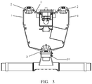
- Figure 3 shows the top view of the medical pendant box body 10 shown in figure 2 .
- Figure 4 shows a partial enlarged view of a portion of the lower part in figure 3 , especially showing the electrical interface and the mechanical interface of the post 2 in the medical pendant box body 10.
- the medical pendant box body 10 of the present invention comprises at least two panels 1, at least two posts 2 extending along the longitudinal direction of the medical pendant box body, an upper base plate 3 and a lower base plate 4; the at least two panels 1 are respectively fixed to the at least two posts 2, the upper base plate 3 and the lower base plate 4 are fixed to the upper edge and the lower edge of each panel 1 of at least two panels 1, respectively.
- At least one post 2 of the at least two posts is provided with an electrical interface
- the electrical interface comprises an inner groove 21 located on the post 2 and extending along the longitudinal direction of the post, an insulator 22 accommodated within the inner groove 21, and a conductor 23 sealed within the insulator 22.
- the medical pendant box body of the present invention can possess a standardised electrical interface, without complicatedly connecting electrical cables, being easy for disassembly and assembly, and the position of a medical accessory capable of being freely adjusted.
- At least one post 2 of the at least two posts is also provided with a mechanical interface, the mechanical interface comprising a concave curved portion 25 for matching to the convex curved portion 35 of the mechanical connecting piece 31.
- the medical pendant box body of the present invention can possess a standardised mechanical interface, being easy for disassembly and assembly, and the position of a medical accessory capable of being freely adjusted. Furthermore, by means of the same post in the medical pendant box body, both the mechanical connection and the electrical connection can be achieved, the number of the components needed is reduced, and the connection reliability is improved.
- posts 2 extend along the longitudinal direction of the medical pendant box body 10 and passing through the entire length of the medical pendant box body 10. In this way, by means of a mechanical connecting piece, the location of the medical accessories can be steplessly adjusted along the longitudinal direction of the medical pendant box body.
- the inner groove 21 extends across the entire length of the post 2.
- the inner groove 21 is located at the front surface of the post 2. In this way, it is easy for the extrusion molding of the post, effectively reducing the processing cost.
- the number of the inner groove 21 on the post 2 is only one. In this way, the simple and reliable electrical connection is realized, meanwhile simplifying the structural design of the post and reducing the processing cost.
- the insulator 22 extends along the longitudinal direction of the post. Preferably, the insulator 22 also extends across the entire length of the post 2.
- the conductor 23 extends along the longitudinal direction of the post. Preferably, the conductor 23 also extends across the entire length of the post 2.
- the medical pendant box body of the present invention can freely adjust the position of a medical accessory across the entire length of the post (or the entire length of the medical pendant box body), and easily and quickly realize the electrical connection and/or the mechanical connection.
- the inner groove 21 is substantially filled when the insulator 22 is accommodated within the inner groove 21 and the conductor 23 is sealed within the insulator 22.
- the electrical interface has good reliability and insulation performance, effectively preventing the infiltration of water or other cleaning agents during the cleaning process in a hospital.
- the number of the insulators 22 within the inner groove 21 is two, and one conductor 23 is sealed within each insulator 22.
- the insulator 22 comprises an insulator front part 221 and an insulator rear part 222.
- the insulator front parts 221 of the two insulators 22 can be formed integrally so as to effectively prevent the infiltration of water or other cleaning agents during the cleaning process in a hospital.
- the cross section of the conductor 23 is substantially Y-shaped.
- the cross section of the conductor 23 can also be substantially ⁇ -shaped.
- the insulator 22 comprises an insulator front part 221 and an insulator rear part 222
- the conductor 23 is sealed within the insulator rear part 222
- the insulator front part 221 has a substantially flat front surface and a gap 223 extending along the longitudinal direction of the medical pendant box body.
- the insulator 22 (comprising an insulator front part 221 and/or an insulator rear part 222) should possess a certain elasticity.
- the insulator front part 221 possesses a certain elasticity.
- the insulator rear part 222 possesses a certain elasticity.
- both the insulator front part 221 and the insulator rear part 222 possess a certain elasticity.
- the width size of the gap 223 and the elasticity of the insulator front part 222 are designed so that the gap 223 can be provided for inserting the plug of the electrical accessory and the insulator front part 221 is substantially sealed before inserting the plug.
- the width size of the inner groove 21 and the elasticity of the insulator 22 are designed to make the insulator 22 (especially insulator rear part 222) produce necessary predeformation so as to produce certain pre-pressure, so that when the plug of an electrical accessory is inserted into the electrical interface to connect to the conductor 23, the pre-pressure prevents the plug from disengaging from the conductor 23.
- the conductor 23 is connected to the control board of the medical pendant via a connector 24.
- the mechanical connecting piece 31 can be used for installing various medical accessories, for example, a control handle, an infusion pole, a display arm, a medical guide rail, etc.
- the height of the medical accessories can be arbitrarily adjusted after the medical accessories are installed on the interfaces of the posts, and they can be interchanged on different posts.
- the conductor 23 provided in post 2 can achieve multiple functions, for example, providing air brake control, electromagnetic brake control, and motor control which are needed for controlling the medical pendant; providing direct current supply, for example, an environment lamp can be directly installed on the conductor; realizing the simultaneous supply of the power and control signals; and supplying video or audio signals, such as the data of a pulsimeter, etc.
Landscapes
- Health & Medical Sciences (AREA)
- Life Sciences & Earth Sciences (AREA)
- Surgery (AREA)
- Engineering & Computer Science (AREA)
- General Health & Medical Sciences (AREA)
- Animal Behavior & Ethology (AREA)
- Veterinary Medicine (AREA)
- Public Health (AREA)
- Medical Informatics (AREA)
- Pathology (AREA)
- Molecular Biology (AREA)
- Heart & Thoracic Surgery (AREA)
- Nuclear Medicine, Radiotherapy & Molecular Imaging (AREA)
- Biomedical Technology (AREA)
- Oral & Maxillofacial Surgery (AREA)
- Structural Engineering (AREA)
- Architecture (AREA)
- Civil Engineering (AREA)
- Nursing (AREA)
- Accommodation For Nursing Or Treatment Tables (AREA)
- Measurement And Recording Of Electrical Phenomena And Electrical Characteristics Of The Living Body (AREA)
- Insulators (AREA)
- Surgical Instruments (AREA)
- Endoscopes (AREA)
Claims (10)
- Corps de boîtier de suspension médicale (10), le corps de boîtier de suspension médicale (10) comprenant au moins deux panneaux (1), au moins deux montants (2) s'étendant le long de la direction longitudinale du corps de boîtier de suspension médicale (10), une plaque de base supérieure (3) et une plaque de base inférieure (4); les au moins deux panneaux (1) sont respectivement fixés aux au moins deux montants (2), la plaque de base supérieure (3) et la plaque de base inférieure (4) sont respectivement fixées au bord supérieur et au bord inférieur de chaque panneau parmi les au moins deux panneaux (1), au moins un montant parmi les au moins deux montants (2) est muni d'une interface électrique, caractérisé en ce que
l'interface électrique comprend une seule gorge interne (21) située au niveau de la surface avant du montant (2) et s'étendant le long de la direction longitudinale du montant, un isolant (22) logé dans la gorge interne (21), et un conducteur (23) scellé à l'intérieur de l'isolant (22). - Corps de boîtier de suspension médicale (10) selon la revendication 1, dans lequel la gorge interne (21) est sensiblement remplie lorsque l'isolant (22) est logé à l'intérieur de la gorge interne (21) et le conducteur (23) est scellé à l'intérieur de l'isolant (22).
- Corps de boîtier de suspension médicale (10) selon la revendication 1, dans lequel le nombre d'isolants (22) dans la gorge interne (21) est de deux, et un conducteur (23) est scellé à l'intérieur de chaque isolant (22).
- Corps de boîtier de suspension médicale (10) selon la revendication 1, dans lequel la coupe transversale du conducteur (23) est sensiblement en forme de Y ou en forme de Ω.
- Corps de boîtier de suspension médicale (10) selon la revendication 1, dans lequel l'isolant (22) comprend une partie avant d'isolant (221) et une partie arrière d'isolant (222), le conducteur (23) est scellé à l'intérieur de la partie arrière d'isolant (222), la partie avant d'isolant (221) présente une surface avant sensiblement plate et un espace (223) s'étendant le long de la direction longitudinale du corps de boîtier de suspension médicale (10).
- Corps de boîtier de suspension médicale (10) selon la revendication 5, dans lequel la taille en largeur de l'espace (223) et l'élasticité de la partie avant d'isolant (221) sont conçues de sorte que l'espace (223) puisse être prévu pour insérer une prise d'un accessoire électrique et la partie avant d'isolant (221) est sensiblement scellée avant l'insertion de la prise.
- Corps de boîtier de suspension médicale (10) selon la revendication 1, dans lequel la taille en largeur de la gorge interne (21) et l'élasticité de l'isolant (22) sont conçues pour amener l'isolant (22) à produire une pré-déformation nécessaire afin de produire une certaine pré-pression, de sorte que, lorsqu'une prise d'un accessoire électrique est insérée dans l'interface électrique pour se connecter au conducteur (23), la pré-pression empêche la prise de se dégager du conducteur (23).
- Corps de boîtier de suspension médicale (10) selon la revendication 1, dans lequel le conducteur (23) est connecté à une carte de commande de la suspension médicale par l'intermédiaire d'un connecteur (24).
- Corps de boîtier de suspension médicale (10) selon la revendication 1, dans lequel au moins un montant parmi les au moins deux montants (2) est également muni d'une interface mécanique, l'interface mécanique comprenant une partie incurvée concave (25) ou une partie incurvée convexe pour s'ajuster à une partie incurvée convexe (35) ou à une partie incurvée concave d'une pièce de connexion mécanique (31).
- Corps de boîtier de suspension médicale (10) selon la revendication 9, dans lequel la pièce de connexion mécanique (31) est utilisée pour installer un accessoire médical.
Applications Claiming Priority (2)
| Application Number | Priority Date | Filing Date | Title |
|---|---|---|---|
| CN201410181261.8A CN103919615B (zh) | 2014-04-30 | 2014-04-30 | 医用吊塔箱体及用于该医用吊塔箱体的立柱 |
| PCT/CN2014/083513 WO2015165160A1 (fr) | 2014-04-30 | 2014-08-01 | Boîtier allongé à usage médical et colonnes associées |
Publications (3)
| Publication Number | Publication Date |
|---|---|
| EP3138528A1 EP3138528A1 (fr) | 2017-03-08 |
| EP3138528A4 EP3138528A4 (fr) | 2017-12-27 |
| EP3138528B1 true EP3138528B1 (fr) | 2020-01-22 |
Family
ID=51138183
Family Applications (1)
| Application Number | Title | Priority Date | Filing Date |
|---|---|---|---|
| EP14890932.8A Active EP3138528B1 (fr) | 2014-04-30 | 2014-08-01 | Boîtier allongé à usage médical et colonnes associées |
Country Status (7)
| Country | Link |
|---|---|
| US (1) | US9707048B2 (fr) |
| EP (1) | EP3138528B1 (fr) |
| JP (1) | JP6379226B2 (fr) |
| CN (1) | CN103919615B (fr) |
| MY (1) | MY178180A (fr) |
| SG (1) | SG11201607074PA (fr) |
| WO (1) | WO2015165160A1 (fr) |
Families Citing this family (2)
| Publication number | Priority date | Publication date | Assignee | Title |
|---|---|---|---|---|
| CN103919615B (zh) | 2014-04-30 | 2017-01-25 | 迈柯唯医疗设备(苏州)有限公司 | 医用吊塔箱体及用于该医用吊塔箱体的立柱 |
| CN104257429A (zh) * | 2014-09-30 | 2015-01-07 | 迈柯唯医疗设备(苏州)有限公司 | 医用吊塔触摸式感应把手 |
Family Cites Families (37)
| Publication number | Priority date | Publication date | Assignee | Title |
|---|---|---|---|---|
| DE2966388D1 (en) * | 1978-07-21 | 1983-12-15 | Electrak Int Ltd | Electrical distribution system |
| NL8200247A (nl) * | 1982-01-22 | 1983-08-16 | Gouda Holland Bv | Roosterplafondconstructie voor het daaraan bevestigen van verplaatsbare ophangzuilen. |
| GB8608900D0 (en) * | 1986-04-11 | 1986-05-14 | Light Source Electrical Equip | Low voltage distribution system |
| CN1036932A (zh) * | 1988-04-12 | 1989-11-08 | 亚利山大·唐纳德·卡拉彼塔 | 改进的悬挂系统 |
| FR2693102B1 (fr) * | 1992-12-14 | 1994-09-30 | Chicoine Medical | Réseau de distribution de fluides médicaux. |
| US5348485A (en) * | 1993-04-12 | 1994-09-20 | Electronic Retailing Systems Int'l Inc. | Electronic price display system with vertical rail |
| CN2195801Y (zh) * | 1994-07-12 | 1995-04-26 | 关铨铭 | 安全插头和插座 |
| AU2002953429A0 (en) * | 2002-12-18 | 2003-01-09 | Power And Communications Logistics Pty Limited | An elongate electrical conductor that is adapted for electrically connecting with an electrical contact |
| US7111957B2 (en) * | 2004-01-12 | 2006-09-26 | Genlyte Thomas Group Llc | Tilt and lock air handling fixture |
| US7513675B2 (en) * | 2004-05-06 | 2009-04-07 | Genlyte Thomas Group Llc | Modular luminaire system with track and ballast attachment means |
| CN2726156Y (zh) * | 2004-08-03 | 2005-09-14 | 孙媛春 | 开关式防触防脱安全插座 |
| US20080214989A1 (en) * | 2004-12-07 | 2008-09-04 | Nakanishi Inc. | Biopolymer Powder Gelating/Jetting Apparatus |
| US7258555B2 (en) * | 2005-03-15 | 2007-08-21 | International Automotive Components Group North America, Inc. | System and method for electrical power track and slidable accessories |
| US7845601B1 (en) * | 2006-11-09 | 2010-12-07 | Modular Services Company | Medical equipment transport system |
| DE102007053327A1 (de) * | 2007-11-08 | 2009-05-14 | Trumpf Medizin Systeme Gmbh + Co.Kg | Medizinische Versorgungseinheit zur Stromversorgung und Datenübertragung bei medizinischen Apparaten |
| DE202008008656U1 (de) * | 2008-06-27 | 2009-11-19 | Weidmüller Interface GmbH & Co. KG | Schutzleiteranschlußvorrichtung aus Metall |
| EP2248503B1 (fr) * | 2009-05-07 | 2013-01-02 | TRUMPF Medizin Systeme GmbH + Co. KG | Unité d'alimentation médicale dotée d'adaptateurs réglables |
| PL2248504T3 (pl) * | 2009-05-07 | 2014-05-30 | Trumpf Medizin Systeme Gmbh & Co Kg | Medyczna jednostka zasilająca z wbudowywanymi modułami |
| CN101940499B (zh) * | 2009-07-06 | 2013-03-06 | 北京谊安医疗系统股份有限公司 | 医用吊塔水平供应柱组合结构 |
| EP2322130B1 (fr) * | 2009-11-16 | 2013-01-16 | TRUMPF Medizin Systeme GmbH + Co. KG | Unité d'alimentation médicale |
| CN201710467U (zh) * | 2010-06-02 | 2011-01-19 | 南京迈瑞生物医疗电子有限公司 | 吊塔气电分离箱 |
| CN201798873U (zh) * | 2010-06-18 | 2011-04-20 | 珠海市奥吉赛科技有限公司 | 医用吊塔 |
| US8992238B2 (en) * | 2010-07-12 | 2015-03-31 | Ferno-Washington, Inc. | Mounting system having a mounting plate with mounting studs and electrical contacts |
| CA2709726C (fr) * | 2010-07-15 | 2016-04-12 | Dean R. Rosendahl | Joint pour panneaux extrudes |
| CN201920915U (zh) * | 2010-12-31 | 2011-08-10 | 北京谊安医疗系统股份有限公司 | 托盘夹紧装置 |
| CN202096297U (zh) * | 2011-05-17 | 2012-01-04 | 上海美和医疗工程有限公司 | 手术室的气体吊塔 |
| CN202236081U (zh) * | 2011-09-01 | 2012-05-30 | 武汉亚洲心脏病医院 | 便携式医用设备带 |
| US8469728B1 (en) * | 2011-12-02 | 2013-06-25 | Tyco Electronics Corporation | Polarity protection for electrified grid and mating connector |
| TW201347743A (zh) * | 2012-05-21 | 2013-12-01 | Syncmold Entpr Corp | 醫療推車系統 |
| US8770993B2 (en) * | 2012-06-01 | 2014-07-08 | Tyco Electronics Corporation | Connector assembly with polarity correction/protection |
| US9146029B2 (en) * | 2012-06-15 | 2015-09-29 | RTC Industries, Incorporated | Power supply with mechanical connections |
| CN103142312B (zh) * | 2013-03-19 | 2015-09-16 | 湖南太阳龙医疗科技有限公司 | 一种具有气电分离装配结构的医用吊塔终端箱 |
| CN203153956U (zh) * | 2013-04-18 | 2013-08-28 | 北京华益精点生物技术有限公司 | 框架式气电分离医用吊塔 |
| CN104055576B (zh) * | 2013-06-19 | 2016-06-22 | 迈柯唯医疗设备(苏州)有限公司 | 医用吊塔系统 |
| CN103591425B (zh) * | 2013-11-15 | 2015-06-03 | 迈柯唯医疗设备(苏州)有限公司 | 用于医用吊塔的可移动式附件固定装置 |
| CN103919615B (zh) * | 2014-04-30 | 2017-01-25 | 迈柯唯医疗设备(苏州)有限公司 | 医用吊塔箱体及用于该医用吊塔箱体的立柱 |
| CN203815593U (zh) * | 2014-04-30 | 2014-09-10 | 迈柯唯医疗设备(苏州)有限公司 | 医用吊塔箱体及用于该医用吊塔箱体的立柱 |
-
2014
- 2014-04-30 CN CN201410181261.8A patent/CN103919615B/zh active Active
- 2014-08-01 JP JP2016572874A patent/JP6379226B2/ja active Active
- 2014-08-01 EP EP14890932.8A patent/EP3138528B1/fr active Active
- 2014-08-01 WO PCT/CN2014/083513 patent/WO2015165160A1/fr not_active Ceased
- 2014-08-01 SG SG11201607074PA patent/SG11201607074PA/en unknown
- 2014-08-01 MY MYPI2016703110A patent/MY178180A/en unknown
-
2016
- 2016-10-06 US US15/287,035 patent/US9707048B2/en active Active
Non-Patent Citations (1)
| Title |
|---|
| None * |
Also Published As
| Publication number | Publication date |
|---|---|
| JP6379226B2 (ja) | 2018-08-22 |
| MY178180A (en) | 2020-10-06 |
| CN103919615B (zh) | 2017-01-25 |
| EP3138528A4 (fr) | 2017-12-27 |
| CN103919615A (zh) | 2014-07-16 |
| US9707048B2 (en) | 2017-07-18 |
| SG11201607074PA (en) | 2016-10-28 |
| US20170035524A1 (en) | 2017-02-09 |
| WO2015165160A1 (fr) | 2015-11-05 |
| JP2017517351A (ja) | 2017-06-29 |
| EP3138528A1 (fr) | 2017-03-08 |
Similar Documents
| Publication | Publication Date | Title |
|---|---|---|
| US9686875B2 (en) | Electrical device with incorporated cable duct | |
| CN107647706B (zh) | 一种货架内置取电系统 | |
| US8979311B2 (en) | Power supply system for adjustable shelving | |
| EP3138528B1 (fr) | Boîtier allongé à usage médical et colonnes associées | |
| TW455007U (en) | Connector for coaxial cables with very fine conductors | |
| EP3772245A1 (fr) | Voie d'alimentation telescopique | |
| CN105040933A (zh) | 墙体结构及利用其的照明系统 | |
| EP3011941B1 (fr) | Système médical pendant | |
| WO2001062054A2 (fr) | Systeme d'interconnexion pour cablage | |
| CN218850035U (zh) | 电源轨道和轨道插座 | |
| US6349655B1 (en) | Wire management system | |
| CN202776863U (zh) | 塑料型六仓结构中心供氧设备带 | |
| SE1251094A1 (sv) | Fjärrstyrd anordning samt tillhörande fjärrkontroll | |
| CN209562981U (zh) | 一种矿用带式输送机驱动保护控制装置 | |
| CN208258222U (zh) | 一种新型终端信息同步装置 | |
| CN103544883A (zh) | 显示装置及空调器 | |
| KR101165035B1 (ko) | 데스크의 전선 배선안내장치 | |
| CN209058779U (zh) | 一种烹饪器具 | |
| EP2587135A1 (fr) | Ensemble lampe DEL | |
| CN209704893U (zh) | 一种风扇遥控开关 | |
| CN220382504U (zh) | 一种医用设备箱 | |
| CN207572549U (zh) | 一种便于接线的接线端子排 | |
| CN215226380U (zh) | 一种展示柜导电装置 | |
| JP6415180B2 (ja) | 壁掛けコントローラ装置 | |
| CN205211609U (zh) | 一种墙壁开关 |
Legal Events
| Date | Code | Title | Description |
|---|---|---|---|
| STAA | Information on the status of an ep patent application or granted ep patent |
Free format text: STATUS: THE INTERNATIONAL PUBLICATION HAS BEEN MADE |
|
| PUAI | Public reference made under article 153(3) epc to a published international application that has entered the european phase |
Free format text: ORIGINAL CODE: 0009012 |
|
| STAA | Information on the status of an ep patent application or granted ep patent |
Free format text: STATUS: REQUEST FOR EXAMINATION WAS MADE |
|
| 17P | Request for examination filed |
Effective date: 20160913 |
|
| AK | Designated contracting states |
Kind code of ref document: A1 Designated state(s): AL AT BE BG CH CY CZ DE DK EE ES FI FR GB GR HR HU IE IS IT LI LT LU LV MC MK MT NL NO PL PT RO RS SE SI SK SM TR |
|
| AX | Request for extension of the european patent |
Extension state: BA ME |
|
| DAX | Request for extension of the european patent (deleted) | ||
| A4 | Supplementary search report drawn up and despatched |
Effective date: 20171129 |
|
| RIC1 | Information provided on ipc code assigned before grant |
Ipc: H01R 25/14 20060101ALI20171123BHEP Ipc: A61B 90/00 20160101AFI20171123BHEP Ipc: H02G 3/04 20060101ALI20171123BHEP Ipc: A61G 12/00 20060101ALI20171123BHEP |
|
| GRAP | Despatch of communication of intention to grant a patent |
Free format text: ORIGINAL CODE: EPIDOSNIGR1 |
|
| STAA | Information on the status of an ep patent application or granted ep patent |
Free format text: STATUS: GRANT OF PATENT IS INTENDED |
|
| INTG | Intention to grant announced |
Effective date: 20191011 |
|
| GRAS | Grant fee paid |
Free format text: ORIGINAL CODE: EPIDOSNIGR3 |
|
| GRAA | (expected) grant |
Free format text: ORIGINAL CODE: 0009210 |
|
| STAA | Information on the status of an ep patent application or granted ep patent |
Free format text: STATUS: THE PATENT HAS BEEN GRANTED |
|
| AK | Designated contracting states |
Kind code of ref document: B1 Designated state(s): AL AT BE BG CH CY CZ DE DK EE ES FI FR GB GR HR HU IE IS IT LI LT LU LV MC MK MT NL NO PL PT RO RS SE SI SK SM TR |
|
| REG | Reference to a national code |
Ref country code: GB Ref legal event code: FG4D |
|
| REG | Reference to a national code |
Ref country code: CH Ref legal event code: EP |
|
| REG | Reference to a national code |
Ref country code: AT Ref legal event code: REF Ref document number: 1226437 Country of ref document: AT Kind code of ref document: T Effective date: 20200215 |
|
| REG | Reference to a national code |
Ref country code: IE Ref legal event code: FG4D |
|
| REG | Reference to a national code |
Ref country code: DE Ref legal event code: R096 Ref document number: 602014060516 Country of ref document: DE |
|
| REG | Reference to a national code |
Ref country code: NL Ref legal event code: MP Effective date: 20200122 |
|
| REG | Reference to a national code |
Ref country code: LT Ref legal event code: MG4D |
|
| PG25 | Lapsed in a contracting state [announced via postgrant information from national office to epo] |
Ref country code: FI Free format text: LAPSE BECAUSE OF FAILURE TO SUBMIT A TRANSLATION OF THE DESCRIPTION OR TO PAY THE FEE WITHIN THE PRESCRIBED TIME-LIMIT Effective date: 20200122 Ref country code: PT Free format text: LAPSE BECAUSE OF FAILURE TO SUBMIT A TRANSLATION OF THE DESCRIPTION OR TO PAY THE FEE WITHIN THE PRESCRIBED TIME-LIMIT Effective date: 20200614 Ref country code: NL Free format text: LAPSE BECAUSE OF FAILURE TO SUBMIT A TRANSLATION OF THE DESCRIPTION OR TO PAY THE FEE WITHIN THE PRESCRIBED TIME-LIMIT Effective date: 20200122 Ref country code: RS Free format text: LAPSE BECAUSE OF FAILURE TO SUBMIT A TRANSLATION OF THE DESCRIPTION OR TO PAY THE FEE WITHIN THE PRESCRIBED TIME-LIMIT Effective date: 20200122 Ref country code: NO Free format text: LAPSE BECAUSE OF FAILURE TO SUBMIT A TRANSLATION OF THE DESCRIPTION OR TO PAY THE FEE WITHIN THE PRESCRIBED TIME-LIMIT Effective date: 20200422 |
|
| PG25 | Lapsed in a contracting state [announced via postgrant information from national office to epo] |
Ref country code: GR Free format text: LAPSE BECAUSE OF FAILURE TO SUBMIT A TRANSLATION OF THE DESCRIPTION OR TO PAY THE FEE WITHIN THE PRESCRIBED TIME-LIMIT Effective date: 20200423 Ref country code: BG Free format text: LAPSE BECAUSE OF FAILURE TO SUBMIT A TRANSLATION OF THE DESCRIPTION OR TO PAY THE FEE WITHIN THE PRESCRIBED TIME-LIMIT Effective date: 20200422 Ref country code: HR Free format text: LAPSE BECAUSE OF FAILURE TO SUBMIT A TRANSLATION OF THE DESCRIPTION OR TO PAY THE FEE WITHIN THE PRESCRIBED TIME-LIMIT Effective date: 20200122 Ref country code: IS Free format text: LAPSE BECAUSE OF FAILURE TO SUBMIT A TRANSLATION OF THE DESCRIPTION OR TO PAY THE FEE WITHIN THE PRESCRIBED TIME-LIMIT Effective date: 20200522 Ref country code: SE Free format text: LAPSE BECAUSE OF FAILURE TO SUBMIT A TRANSLATION OF THE DESCRIPTION OR TO PAY THE FEE WITHIN THE PRESCRIBED TIME-LIMIT Effective date: 20200122 Ref country code: LV Free format text: LAPSE BECAUSE OF FAILURE TO SUBMIT A TRANSLATION OF THE DESCRIPTION OR TO PAY THE FEE WITHIN THE PRESCRIBED TIME-LIMIT Effective date: 20200122 |
|
| REG | Reference to a national code |
Ref country code: DE Ref legal event code: R097 Ref document number: 602014060516 Country of ref document: DE |
|
| PG25 | Lapsed in a contracting state [announced via postgrant information from national office to epo] |
Ref country code: ES Free format text: LAPSE BECAUSE OF FAILURE TO SUBMIT A TRANSLATION OF THE DESCRIPTION OR TO PAY THE FEE WITHIN THE PRESCRIBED TIME-LIMIT Effective date: 20200122 Ref country code: EE Free format text: LAPSE BECAUSE OF FAILURE TO SUBMIT A TRANSLATION OF THE DESCRIPTION OR TO PAY THE FEE WITHIN THE PRESCRIBED TIME-LIMIT Effective date: 20200122 Ref country code: SM Free format text: LAPSE BECAUSE OF FAILURE TO SUBMIT A TRANSLATION OF THE DESCRIPTION OR TO PAY THE FEE WITHIN THE PRESCRIBED TIME-LIMIT Effective date: 20200122 Ref country code: DK Free format text: LAPSE BECAUSE OF FAILURE TO SUBMIT A TRANSLATION OF THE DESCRIPTION OR TO PAY THE FEE WITHIN THE PRESCRIBED TIME-LIMIT Effective date: 20200122 Ref country code: RO Free format text: LAPSE BECAUSE OF FAILURE TO SUBMIT A TRANSLATION OF THE DESCRIPTION OR TO PAY THE FEE WITHIN THE PRESCRIBED TIME-LIMIT Effective date: 20200122 Ref country code: SK Free format text: LAPSE BECAUSE OF FAILURE TO SUBMIT A TRANSLATION OF THE DESCRIPTION OR TO PAY THE FEE WITHIN THE PRESCRIBED TIME-LIMIT Effective date: 20200122 Ref country code: CZ Free format text: LAPSE BECAUSE OF FAILURE TO SUBMIT A TRANSLATION OF THE DESCRIPTION OR TO PAY THE FEE WITHIN THE PRESCRIBED TIME-LIMIT Effective date: 20200122 Ref country code: LT Free format text: LAPSE BECAUSE OF FAILURE TO SUBMIT A TRANSLATION OF THE DESCRIPTION OR TO PAY THE FEE WITHIN THE PRESCRIBED TIME-LIMIT Effective date: 20200122 |
|
| REG | Reference to a national code |
Ref country code: AT Ref legal event code: MK05 Ref document number: 1226437 Country of ref document: AT Kind code of ref document: T Effective date: 20200122 |
|
| PLBE | No opposition filed within time limit |
Free format text: ORIGINAL CODE: 0009261 |
|
| STAA | Information on the status of an ep patent application or granted ep patent |
Free format text: STATUS: NO OPPOSITION FILED WITHIN TIME LIMIT |
|
| 26N | No opposition filed |
Effective date: 20201023 |
|
| PG25 | Lapsed in a contracting state [announced via postgrant information from national office to epo] |
Ref country code: IT Free format text: LAPSE BECAUSE OF FAILURE TO SUBMIT A TRANSLATION OF THE DESCRIPTION OR TO PAY THE FEE WITHIN THE PRESCRIBED TIME-LIMIT Effective date: 20200122 Ref country code: AT Free format text: LAPSE BECAUSE OF FAILURE TO SUBMIT A TRANSLATION OF THE DESCRIPTION OR TO PAY THE FEE WITHIN THE PRESCRIBED TIME-LIMIT Effective date: 20200122 |
|
| PG25 | Lapsed in a contracting state [announced via postgrant information from national office to epo] |
Ref country code: PL Free format text: LAPSE BECAUSE OF FAILURE TO SUBMIT A TRANSLATION OF THE DESCRIPTION OR TO PAY THE FEE WITHIN THE PRESCRIBED TIME-LIMIT Effective date: 20200122 Ref country code: SI Free format text: LAPSE BECAUSE OF FAILURE TO SUBMIT A TRANSLATION OF THE DESCRIPTION OR TO PAY THE FEE WITHIN THE PRESCRIBED TIME-LIMIT Effective date: 20200122 |
|
| PG25 | Lapsed in a contracting state [announced via postgrant information from national office to epo] |
Ref country code: MC Free format text: LAPSE BECAUSE OF FAILURE TO SUBMIT A TRANSLATION OF THE DESCRIPTION OR TO PAY THE FEE WITHIN THE PRESCRIBED TIME-LIMIT Effective date: 20200122 |
|
| REG | Reference to a national code |
Ref country code: CH Ref legal event code: PL |
|
| PG25 | Lapsed in a contracting state [announced via postgrant information from national office to epo] |
Ref country code: CH Free format text: LAPSE BECAUSE OF NON-PAYMENT OF DUE FEES Effective date: 20200831 Ref country code: LU Free format text: LAPSE BECAUSE OF NON-PAYMENT OF DUE FEES Effective date: 20200801 Ref country code: LI Free format text: LAPSE BECAUSE OF NON-PAYMENT OF DUE FEES Effective date: 20200831 |
|
| REG | Reference to a national code |
Ref country code: BE Ref legal event code: MM Effective date: 20200831 |
|
| PG25 | Lapsed in a contracting state [announced via postgrant information from national office to epo] |
Ref country code: BE Free format text: LAPSE BECAUSE OF NON-PAYMENT OF DUE FEES Effective date: 20200831 Ref country code: IE Free format text: LAPSE BECAUSE OF NON-PAYMENT OF DUE FEES Effective date: 20200801 |
|
| PG25 | Lapsed in a contracting state [announced via postgrant information from national office to epo] |
Ref country code: TR Free format text: LAPSE BECAUSE OF FAILURE TO SUBMIT A TRANSLATION OF THE DESCRIPTION OR TO PAY THE FEE WITHIN THE PRESCRIBED TIME-LIMIT Effective date: 20200122 Ref country code: MT Free format text: LAPSE BECAUSE OF FAILURE TO SUBMIT A TRANSLATION OF THE DESCRIPTION OR TO PAY THE FEE WITHIN THE PRESCRIBED TIME-LIMIT Effective date: 20200122 Ref country code: CY Free format text: LAPSE BECAUSE OF FAILURE TO SUBMIT A TRANSLATION OF THE DESCRIPTION OR TO PAY THE FEE WITHIN THE PRESCRIBED TIME-LIMIT Effective date: 20200122 |
|
| PG25 | Lapsed in a contracting state [announced via postgrant information from national office to epo] |
Ref country code: MK Free format text: LAPSE BECAUSE OF FAILURE TO SUBMIT A TRANSLATION OF THE DESCRIPTION OR TO PAY THE FEE WITHIN THE PRESCRIBED TIME-LIMIT Effective date: 20200122 Ref country code: AL Free format text: LAPSE BECAUSE OF FAILURE TO SUBMIT A TRANSLATION OF THE DESCRIPTION OR TO PAY THE FEE WITHIN THE PRESCRIBED TIME-LIMIT Effective date: 20200122 |
|
| PGFP | Annual fee paid to national office [announced via postgrant information from national office to epo] |
Ref country code: GB Payment date: 20250612 Year of fee payment: 12 |
|
| PGFP | Annual fee paid to national office [announced via postgrant information from national office to epo] |
Ref country code: FR Payment date: 20250610 Year of fee payment: 12 |
|
| PGFP | Annual fee paid to national office [announced via postgrant information from national office to epo] |
Ref country code: DE Payment date: 20250611 Year of fee payment: 12 |