EP3138631A1 - Sammlung und erkennung einer integrierten vorrichtung mit mis-anordnungsvermeidungsstruktur - Google Patents
Sammlung und erkennung einer integrierten vorrichtung mit mis-anordnungsvermeidungsstruktur Download PDFInfo
- Publication number
- EP3138631A1 EP3138631A1 EP16794199.6A EP16794199A EP3138631A1 EP 3138631 A1 EP3138631 A1 EP 3138631A1 EP 16794199 A EP16794199 A EP 16794199A EP 3138631 A1 EP3138631 A1 EP 3138631A1
- Authority
- EP
- European Patent Office
- Prior art keywords
- detector
- test strip
- collector
- strip holder
- detecting device
- Prior art date
- Legal status (The legal status is an assumption and is not a legal conclusion. Google has not performed a legal analysis and makes no representation as to the accuracy of the status listed.)
- Granted
Links
Images









Classifications
-
- B—PERFORMING OPERATIONS; TRANSPORTING
- B01—PHYSICAL OR CHEMICAL PROCESSES OR APPARATUS IN GENERAL
- B01L—CHEMICAL OR PHYSICAL LABORATORY APPARATUS FOR GENERAL USE
- B01L3/00—Containers or dishes for laboratory use, e.g. laboratory glassware; Droppers
- B01L3/50—Containers for the purpose of retaining a material to be analysed, e.g. test tubes
- B01L3/508—Rigid containers without fluid transport within
-
- A—HUMAN NECESSITIES
- A61—MEDICAL OR VETERINARY SCIENCE; HYGIENE
- A61B—DIAGNOSIS; SURGERY; IDENTIFICATION
- A61B10/00—Instruments for taking body samples for diagnostic purposes; Other methods or instruments for diagnosis, e.g. for vaccination diagnosis, sex determination or ovulation-period determination; Throat striking implements
- A61B10/0038—Devices for taking faeces samples; Faecal examination devices
-
- B—PERFORMING OPERATIONS; TRANSPORTING
- B01—PHYSICAL OR CHEMICAL PROCESSES OR APPARATUS IN GENERAL
- B01L—CHEMICAL OR PHYSICAL LABORATORY APPARATUS FOR GENERAL USE
- B01L3/00—Containers or dishes for laboratory use, e.g. laboratory glassware; Droppers
- B01L3/50—Containers for the purpose of retaining a material to be analysed, e.g. test tubes
- B01L3/502—Containers for the purpose of retaining a material to be analysed, e.g. test tubes with fluid transport, e.g. in multi-compartment structures
-
- G—PHYSICS
- G01—MEASURING; TESTING
- G01N—INVESTIGATING OR ANALYSING MATERIALS BY DETERMINING THEIR CHEMICAL OR PHYSICAL PROPERTIES
- G01N1/00—Sampling; Preparing specimens for investigation
- G01N1/02—Devices for withdrawing samples
- G01N1/04—Devices for withdrawing samples in the solid state, e.g. by cutting
- G01N1/08—Devices for withdrawing samples in the solid state, e.g. by cutting involving an extracting tool, e.g. core bit
-
- G—PHYSICS
- G01—MEASURING; TESTING
- G01N—INVESTIGATING OR ANALYSING MATERIALS BY DETERMINING THEIR CHEMICAL OR PHYSICAL PROPERTIES
- G01N33/00—Investigating or analysing materials by specific methods not covered by groups G01N1/00 - G01N31/00
- G01N33/48—Biological material, e.g. blood, urine; Haemocytometers
- G01N33/50—Chemical analysis of biological material, e.g. blood, urine; Testing involving biospecific ligand binding methods; Immunological testing
- G01N33/53—Immunoassay; Biospecific binding assay; Materials therefor
- G01N33/543—Immunoassay; Biospecific binding assay; Materials therefor with an insoluble carrier for immobilising immunochemicals
- G01N33/54366—Apparatus specially adapted for solid-phase testing
-
- B—PERFORMING OPERATIONS; TRANSPORTING
- B01—PHYSICAL OR CHEMICAL PROCESSES OR APPARATUS IN GENERAL
- B01L—CHEMICAL OR PHYSICAL LABORATORY APPARATUS FOR GENERAL USE
- B01L2200/00—Solutions for specific problems relating to chemical or physical laboratory apparatus
- B01L2200/02—Adapting objects or devices to another
- B01L2200/025—Align devices or objects to ensure defined positions relative to each other
-
- B—PERFORMING OPERATIONS; TRANSPORTING
- B01—PHYSICAL OR CHEMICAL PROCESSES OR APPARATUS IN GENERAL
- B01L—CHEMICAL OR PHYSICAL LABORATORY APPARATUS FOR GENERAL USE
- B01L2300/00—Additional constructional details
- B01L2300/02—Identification, exchange or storage of information
- B01L2300/021—Identification, e.g. bar codes
-
- B—PERFORMING OPERATIONS; TRANSPORTING
- B01—PHYSICAL OR CHEMICAL PROCESSES OR APPARATUS IN GENERAL
- B01L—CHEMICAL OR PHYSICAL LABORATORY APPARATUS FOR GENERAL USE
- B01L2300/00—Additional constructional details
- B01L2300/04—Closures and closing means
- B01L2300/046—Function or devices integrated in the closure
-
- B—PERFORMING OPERATIONS; TRANSPORTING
- B01—PHYSICAL OR CHEMICAL PROCESSES OR APPARATUS IN GENERAL
- B01L—CHEMICAL OR PHYSICAL LABORATORY APPARATUS FOR GENERAL USE
- B01L2300/00—Additional constructional details
- B01L2300/06—Auxiliary integrated devices, integrated components
- B01L2300/0609—Holders integrated in container to position an object
-
- B—PERFORMING OPERATIONS; TRANSPORTING
- B01—PHYSICAL OR CHEMICAL PROCESSES OR APPARATUS IN GENERAL
- B01L—CHEMICAL OR PHYSICAL LABORATORY APPARATUS FOR GENERAL USE
- B01L2300/00—Additional constructional details
- B01L2300/06—Auxiliary integrated devices, integrated components
- B01L2300/0627—Sensor or part of a sensor is integrated
- B01L2300/0663—Whole sensors
-
- B—PERFORMING OPERATIONS; TRANSPORTING
- B01—PHYSICAL OR CHEMICAL PROCESSES OR APPARATUS IN GENERAL
- B01L—CHEMICAL OR PHYSICAL LABORATORY APPARATUS FOR GENERAL USE
- B01L2300/00—Additional constructional details
- B01L2300/06—Auxiliary integrated devices, integrated components
- B01L2300/0672—Integrated piercing tool
-
- B—PERFORMING OPERATIONS; TRANSPORTING
- B01—PHYSICAL OR CHEMICAL PROCESSES OR APPARATUS IN GENERAL
- B01L—CHEMICAL OR PHYSICAL LABORATORY APPARATUS FOR GENERAL USE
- B01L2300/00—Additional constructional details
- B01L2300/08—Geometry, shape and general structure
- B01L2300/0809—Geometry, shape and general structure rectangular shaped
- B01L2300/0825—Test strips
-
- B—PERFORMING OPERATIONS; TRANSPORTING
- B01—PHYSICAL OR CHEMICAL PROCESSES OR APPARATUS IN GENERAL
- B01L—CHEMICAL OR PHYSICAL LABORATORY APPARATUS FOR GENERAL USE
- B01L2300/00—Additional constructional details
- B01L2300/08—Geometry, shape and general structure
- B01L2300/0848—Specific forms of parts of containers
- B01L2300/0858—Side walls
Definitions
- the invention relates to the field of medical detections, specifically to a faeces sampling and detecting device, and particularly to an integrated sampling and detecting device with a misassembled prevention structure.
- a collector of a faeces sampling and detecting device in the traditional art is bonded with a bar code
- the collector bonded with the bar code is assembled into a detector of the faeces sampling and detecting device
- the side, bonded with the bar code, of the collector is easily misassembled into a side, close to a test strip holder, of the detector without correct attachment to the detector due to the fact that the collector is of a symmetric regular structure, thereby influencing reading of the bar code.
- the invention provides an integrated sampling and detecting device with a misassembly prevention structure, which is intended to solve the problem that a side, bonded with a bar code, of a collector is misassembled into a side, close to a test strip holder, of a detector.
- the integrated sampling and detecting device with a misassembly prevention structure may include: a detector; a test strip holder, provided in the detector detachably; a collector, accommodated in the detector detachably; a faeces collection piece and a cushion block, configured to seal the collector detachably; and a piercing part, provided on a bottom surface of the detector and configured to pierce the collector, wherein the test strip holder and the collector are accommodated in the detector side by side, the collector is located between the test strip holder and the detector, a first outer side face of the collector is adjacent to an inner side wall of the detector, a second outer side face of the collector is adjacent to the test strip holder, and the first outer side face and the second outer side face of the collector are asymmetric structurally.
- first outer side face of the collector is a plane
- second outer side face of the collector is a curved surface
- the second outer side face of the collector is a convex arc-shaped surface.
- a recess area may be arranged on the second outer side face of the collector, and the recess area is provided with a convex rib or a convex needle-shaped body or a convex column body of the collector.
- the integrated sampling and detecting device with a misassembly prevention structure further comprises: a supporting platform provided at a bottom of the detector and configured to support the collector.
- the piercing part is an annular body, a top surface of the annular body is a spiral surface, and the top surface of the annular body may be provided with a sharp corner.
- the piercing part comprises: a pointed cone body and an annular frustum surrounding the pointed cone body, the pointed cone body is higher than the annular frustum, an annular clearance is provided between the pointed cone body and the annular frustum, a side surface of the annular frustum is provided with an opening, the opening faces the test strip holder, and the annular clearance is communicated with the opening to form a liquid flow passage.
- annular body is provided with a taper for flow guide from top to bottom.
- the piercing part comprises: a piercing needle and three prisms provided evenly around the piercing needle and connected with the piercing needle, the piercing needle is higher than the three prisms.
- the annular body comprises two pairs of semi-rings, the two semi-rings of each pair are opposite to each other; the four semi-rings are provided side by side; and the piercing part further comprises: a T-shaped prism, an outer side of each of two peripheral semi-rings which are provided at the outer sides of the four semi-rings are connected with the T-shaped prism.
- the side face of the test strip holder is provided with a slope decreasing from top to bottom, and an inner side of the detector may be provided with a convex rib, corresponding to the slope of the test strip holder, of the detector.
- a trench is provided on an outer side of the test strip holder, a test strip is mounted on the trench, an inner wall of one side, adjacent to the test strip, of the detector is provided with a slope from top to bottom, three other inner walls of the detector are provided with slopes from the top to a detector critical line, a straight wall vertical to the bottom surface of the detector is provided below the detector critical line, and the detector critical line is provided on the inner wall of the detector and vertical to a length direction of the detector.
- test strip holder critical line is provided on an inner side of the test strip holder, the inner side of the test strip holder is provided with a slope from the top to the test strip holder critical line, and a straight wall vertical to the bottom surface of the detector is provided below the test strip holder critical line.
- a die drawing direction of the collector is inward die drawing from bottom to top, a lower end of the collector is larger than an upper end of the collector, and a lower end of the detector is smaller than an upper end of the detector.
- the annular body comprises two pairs of semi-rings, the two semi-rings of each pair are opposite to each other; the four semi-rings are provided side by side; and an outer side of each of two peripheral semi-rings which are provided at the outer sides of the four semi-rings are connected with a T-shaped prism.
- a trench is provided on an outer side of the test strip holder, a test strip is mounted on the trench, an inner wall of one side, adjacent to the test strip, of the detector is provided with a slope from top to bottom, three other inner walls of the detector are provided with slopes from the top to a detector critical line, the three other inner walls, below the detector critical line, of the detector are straight walls vertical to the bottom surface of the detector, and the detector critical line is provided on the inner wall of the detector and vertical to a length direction of the detector.
- test strip holder critical line is provided on an inner side of the test strip holder, an inner wall of the test strip holder is provided with a slope from the top to the test strip holder critical line, and the inner wall, below the test strip holder critical line, of the test strip holder is a straight wall vertical to the bottom surface of the detector.
- two outer side faces of a collector are asymmetric structurally.
- a side face bonded with a bar code can be obviously distinguished from a side face facing a detector or attached to the detector.
- the side face, not bonded with a bar code, of the collector is set as a convex arc-shaped surface, a recess area is provided on the convex arc-shaped surface, and the recess area is provided with a convex rib or a convex needle-shaped body or a convex column body of the collector, such that it is very difficult to bond the side face, not bonded with a bar code, of the collector with a bar code, thereby avoiding a phenomenon of mis-bonding of a bar code.
- a die drawing direction of the collector is inward die drawing from bottom to top, and accordingly, a lower end of the collector is larger than an upper end of the collector while a lower end of the detector is smaller than an upper end of the detector.
- a misassembly prevention effect can be achieved at the beginning of mounting, such that the problem that the side, bonded with the bar code, of the collector is misassembled into the side, close to the test strip holder, of the detector is fundamentally avoided, and correct mounting of the collector bonded with the bar code and normal reading of the bar code are achieved.
- the invention provides an integrated sampling and detecting device with a misassembly prevention structure, which is also called as a faeces detection device.
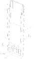
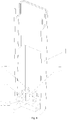
- the integrated sampling and detecting device with a misassembly prevention structure comprises: a detector 1 (as shown in Fig. 2, Fig. 3 and Fig.
- the detector is barrel-shaped, for instance, square barrel-shaped, and is also called as a detection barrel, and a bottom is provided with a detector bottom surface 10); a test strip holder 7, provided in the detector 1 detachably; a collector 3, accommodated in the detector detachably; a faeces collection piece 4 and a cushion block 5, configured to seal the collector 3 detachably; and a piercing part (for instance, an annular body 15 with reference to Fig. 5 ), provided on a bottom surface 10 of the detector and configured to pierce the collector.
- a test strip holder 7 provided in the detector 1 detachably
- a collector 3 accommodated in the detector detachably
- a faeces collection piece 4 and a cushion block 5 configured to seal the collector 3 detachably
- a piercing part for instance, an annular body 15 with reference to Fig. 5
- the test strip holder 7 and the collector 3 are accommodated in the detector 1 side by side, and the collector 3 is located between the test strip holder 7 and the detector 1.
- a first outer side face 31 of the collector 3 is adjacent to an inner side wall of the detector 1
- a second outer side face 32 of the collector is adjacent to the test strip holder 7, and the first outer side face 31 and the second outer side face 32 of the collector are asymmetric structurally.
- two side faces of the collector can be obviously distinguished, and which side face bonded with a bar code and which side face faced a detector or clung to the detector can be judged. So, the problem that a side, bonded with a bar code, of a collector is misassembled into a side, close to a test strip holder, of a detector is solved.
- the first outer side face 31 of the collector can be bonded with a text label of a bar code, thereby avoiding mis-bonding of the bar code.
- a recess area is provided on the second outer side face 32, not bonded with a bar code, of the collector 3, and the recess area is provided with a convex rib or a convex needle-shaped body or a convex column body of the collector, such that it is very difficult to bond the second outer side face 32, not bonded with a bar code, with a bar code, thereby avoiding a phenomenon of mis-bonding of a bar code.
- the integrated sampling and detecting device with a misassembly prevention structure may further comprise: the cushion block 5 in threaded connection with the faeces collection piece 4, an aluminium foil 6 packaged at a bottom of the collector 3, a test strip 8 mounted on the test strip holder 7, and a transparent label 9 covering the test strip 8.
- Other structures of the integrated sampling and detecting device with a misassembly prevention structure or relevant functions and structures not mentioned by the above parts may adopt a relevant technology in CN201320139144.6 or refer to descriptions in CN201320139144.6 .
- the first outer side face 31 of the collector is a plane configured to bond a bar code
- the second outer side face 32 of the collector is a curved surface configured to prevent or hinder bonding of the bar code and configured to fit the test strip holder.
- the second outer side face 32 of the collector is a convex arc-shaped surface.
- the second outer side face 32 is circular arc-shaped.
- a recess area is provided on the second outer side face 32 of the collector.
- a recess area is provided on the circular arc-shaped second outer side face 32, and the recess area is provided with a convex rib or a convex needle-shaped body or a convex column body of the collector.
- bonding of the bar code can be further prevented.
- the integrated sampling and detecting device with a misassembly prevention structure further comprises: a supporting platform 11 provided at a bottom of the detector and configured to support the collector.
- the supporting platform 11 is provided on the bottom surface 10 of the detector and protrudes from the bottom surface 10 of the detector, thereby ensuring a certain distance between the bottom of the collector and the bottom surface of the detector, and making it convenient for a diluent with a faeces sample to flow out.
- Fig. 7 and Fig. 8 show a first piercing part
- the piercing part is an annular body 15
- a top surface 151 of the annular body is a spiral surface
- the top surface of the annular body is provided with a sharp corner.
- the annular body 15 comprises two pairs of semi-rings such as semi circular rings, the two semi-rings of each pair are opposite to each other; a pair of openings 152 is reserved in each pair of opposite semi circular rings; and two pairs of openings 152 are parallel to each other, in order that the diluent with the faeces sample flows out after the bottom of the collector is pierced.
- Fig. 20, Fig. 21 and Fig. 22 show a second piercing part
- the piercing part comprises: a pointed cone body 13 and an annular frustum 14 surrounding the pointed cone body, the pointed cone body 13 is higher than the annular frustum 14, and the annular frustum 14 has a taper from top to bottom, thereby improving the probability of piercing.
- An annular clearance is provided between the pointed cone body and the annular frustum, a side surface of each annular frustum is provided with an opening 142, the opening faces the test strip holder, and the annular clearance is communicated with the opening 142 to form a liquid flow passage, thereby making it convenient for the diluent with the faeces sample to flow out.
- the second piercing part improves the probability of piercing and makes it convenient for the diluent with the faeces sample to flow out to the side of the test strip holder.
- Fig. 23 , Fig. 24 and Fig. 25 show a third piercing part, and the third piercing part is improved on the basis of the first piercing part.
- the main improvement is embodied in that an annular body 16 (comprising inner and outer sides of the annular body 16) is provided with a taper for flow guide from top to bottom.
- the annular body 16 comprises two pairs of semi circular rings, the two semi circular rings of each pair are opposite to each other; a pair of openings 162 is reserved in each pair of opposite semi circular rings; and two pairs of openings 162 are parallel to each other, in order that the diluent with the faeces sample flows out after the bottom of the collector is pierced.
- the third piercing part can guide the diluent with the faeces sample to flow out.
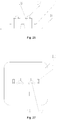
- Fig. 26 and Fig. 27 show a fourth piercing part
- the piercing part comprises: a piercing needle 17 and three prisms 18 provided evenly around the piercing needle and connected with the piercing needle, each of the prisms 18 is a rectangular-shaped, the piercing needle 17 being higher than the three prisms 18.
- the prisms 18 can pierce the bottom of the collector, thereby improving the probability of piercing.
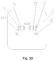
- Fig. 28, Fig. 29 and Fig. 30 show a fifth piercing part, and the fifth piercing part is added with a T-shaped prism 19 on the basis of the first piercing part.
- the annular body 15 comprises four semi-rings divided into two pairs of semi-rings, the two semi-rings of each pair are opposite to each other; the four semi-rings are provided side by side; and an outer side of each of two peripheral semi-rings which are provided at the outer sides of the four semi-rings are connected with a T-shaped prism.
- the T-shaped prism 19 is provided with an edge 191 and an edge 192 configured to pierce the aluminium foil at the bottom of the collector, such that the probability of piercing is improved.
- the side face of the test strip holder 7 is provided with a slope decreasing from top to bottom.
- the inner side of the detector is provided with a convex rib 111, corresponding to the slope of the test strip holder, of the detector. The slope matches with the slope of the test strip holder , such that the test strip holder can be assembled into the detector and clung to the detector at the same time when the test strip holder is assembled into the detector, thereby making a fit part of the test strip holder and the detector self-sealed.
- a trench 71 is provided on an outer side 70 of the test strip holder, and a test strip 8 is mounted on the trench.
- a test strip 8 is mounted on the trench.
- an inner wall of one side, adjacent to the test strip, of the detector is provided with a slope from top to bottom, the slope gradually decreases, three other inner walls of the detector are provided with slopes from the top to a detector critical line 113 (also called as an edge on the inner wall of the detector), the slope gradually decreases, a straight wall vertical to a bottom surface of the detector is provided below the detector critical line 113, and the detector critical line 113 is provided on an inner wall of the detector and vertical to a length direction of the detector 1.
- the detector critical line is provided on the side, close to the collector, of the detector, starts from a convex rib on one side of the detector and terminates to a convex rib on the other side of the detector.
- the detector critical line is located at a position, 1/3 to 1/2 of a height of the whole detector, below a top opening.
- a die drawing direction of the collector is inward die drawing from bottom to top, and accordingly, a lower end of the collector is larger than an upper end of the collector while a lower end of the detector is smaller than an upper end of the detector.
- the faeces collection piece 4, the cushion block 5, the collector 3, the test strip holder 7 and the detector 1 are smoothly assembled without interference.
- the directions of arc surfaces of the faeces collection piece 4 and the cushion block 5 must be consistent with the direction of an arc surface of the collector 3.
- the combination of the faeces collection piece 4, the cushion block 5 and the collector 3 has forward and reverse properties, so the faeces collection piece 4, the cushion block 5 and the collector 3 can be smoothly assembled into the detector 1.
- the second outer side face 32 of the collector 3 is in a convex circular arc shape
- the first outer side face 31 is a plane
- an inner wall 72 of the test strip holder is in a recessed circular arc shape for instance
- the circular arc-shaped second outer side face 32 matches with the inner wall 72 of the test strip holder.
- a test strip holder critical line 75 (also called as an edge on the inner wall of the test strip holder) provided on the inner wall 72 of the test strip holder, the inner wall of the test strip holder is provided with a slope from the top to the test strip holder critical line 75, the slope gradually decreases, and a straight wall vertical to the bottom surface of the detector is provided below the test strip holder critical line 75.
- the test strip holder critical line 75 is vertical to a length direction of the test strip holder and matches with the detector critical line.
- the test strip holder critical line is located, for instance, at a position, 1/3 to 1/2 of the height of the whole test strip holder, from the top end of the test strip holder.
- the straight wall structures below the critical lines of the test strip holder and the detector facilitate in-place press of the collector.
- the integrated sampling and detecting device with a misassembly prevention structure of the invention is improved in terms of shapes of a faeces collection piece, a cushion block, a collector and a test strip holder of a prior faeces sampling and detecting device, and a symmetric regular structure of the faeces collection piece, the cushion block, the collector and the test strip holder is improved into an asymmetric irregular structure of the faeces collection piece, the cushion block, the collector and the test strip holder.
- a die drawing direction of the collector is inward die drawing from bottom to top, and accordingly, a lower end of the collector is larger than an upper end of the collector while a lower end of the detector is smaller than an upper end of the detector.
- a misassembly prevention effect can be achieved at a beginning of mounting, such that the problem that the side, bonded with the bar code, of the collector is misassembled into the side, close to the test strip holder, of the detector is fundamentally avoided, and correct mounting of the collector bonded with the bar code and normal reading of the bar code are achieved.
Landscapes
- Health & Medical Sciences (AREA)
- Chemical & Material Sciences (AREA)
- Life Sciences & Earth Sciences (AREA)
- General Health & Medical Sciences (AREA)
- Immunology (AREA)
- Engineering & Computer Science (AREA)
- Hematology (AREA)
- Analytical Chemistry (AREA)
- Biomedical Technology (AREA)
- Pathology (AREA)
- Molecular Biology (AREA)
- Chemical Kinetics & Catalysis (AREA)
- Clinical Laboratory Science (AREA)
- Biochemistry (AREA)
- General Physics & Mathematics (AREA)
- Urology & Nephrology (AREA)
- Physics & Mathematics (AREA)
- Medical Informatics (AREA)
- Veterinary Medicine (AREA)
- Public Health (AREA)
- Animal Behavior & Ethology (AREA)
- Surgery (AREA)
- Heart & Thoracic Surgery (AREA)
- Biotechnology (AREA)
- Food Science & Technology (AREA)
- Medicinal Chemistry (AREA)
- Cell Biology (AREA)
- Microbiology (AREA)
- Investigating Or Analysing Biological Materials (AREA)
- Sampling And Sample Adjustment (AREA)
- Investigating Or Analysing Materials By The Use Of Chemical Reactions (AREA)
Applications Claiming Priority (2)
| Application Number | Priority Date | Filing Date | Title |
|---|---|---|---|
| CN201510284103.XA CN104849440B (zh) | 2015-05-28 | 2015-05-28 | 带有防误装结构的采集检测一体装置 |
| PCT/CN2016/082666 WO2016188362A1 (zh) | 2015-05-28 | 2016-05-19 | 带有防误装结构的采集检测一体装置 |
Publications (3)
| Publication Number | Publication Date |
|---|---|
| EP3138631A1 true EP3138631A1 (de) | 2017-03-08 |
| EP3138631A4 EP3138631A4 (de) | 2017-09-06 |
| EP3138631B1 EP3138631B1 (de) | 2018-12-26 |
Family
ID=53849238
Family Applications (1)
| Application Number | Title | Priority Date | Filing Date |
|---|---|---|---|
| EP16794199.6A Not-in-force EP3138631B1 (de) | 2015-05-28 | 2016-05-19 | Sammlung und erkennung einer integrierten vorrichtung mit mis-anordnungsvermeidungsstruktur |
Country Status (7)
| Country | Link |
|---|---|
| US (1) | US10384205B2 (de) |
| EP (1) | EP3138631B1 (de) |
| CN (1) | CN104849440B (de) |
| AU (1) | AU2016269287A1 (de) |
| CA (1) | CA2954398A1 (de) |
| ES (1) | ES2716450T3 (de) |
| WO (1) | WO2016188362A1 (de) |
Families Citing this family (6)
| Publication number | Priority date | Publication date | Assignee | Title |
|---|---|---|---|---|
| CN104849440B (zh) * | 2015-05-28 | 2017-07-11 | 万华普曼生物工程有限公司 | 带有防误装结构的采集检测一体装置 |
| CN105334077B (zh) * | 2015-11-26 | 2019-04-19 | 浙江东方基因生物制品有限公司 | 一种流体的快速检测装置 |
| CN206095710U (zh) * | 2016-08-19 | 2017-04-12 | 万华普曼生物工程有限公司 | 采集检测一体装置 |
| CN106680477B (zh) * | 2017-02-14 | 2019-03-01 | 杭州诺辉健康科技有限公司 | 一种粪便取样及隐血检测一体化装置 |
| KR102333133B1 (ko) * | 2021-07-29 | 2021-12-02 | 한경준 | 일체형 자가검사키트 |
| CN120778434A (zh) * | 2024-04-02 | 2025-10-14 | 浙江东方基因生物制品股份有限公司 | 一种测试样本中被分析物质的装置 |
Family Cites Families (23)
| Publication number | Priority date | Publication date | Assignee | Title |
|---|---|---|---|---|
| US20040133128A1 (en) | 2003-01-04 | 2004-07-08 | Zhumin Guan | Assay device with attachable seal for use with specimen collection and assay containers |
| WO2004084727A1 (ja) * | 2003-03-27 | 2004-10-07 | Terumo Kabushiki Kaisha | 体液採取具および体液採取方法 |
| EP1687621B1 (de) | 2003-11-14 | 2018-06-27 | Alere Switzerland GmbH | Probensammelgefäss mit integriertem aktivierbarem probenanalysesystem |
| JP2005164509A (ja) * | 2003-12-05 | 2005-06-23 | Hitachi High-Technologies Corp | 試薬容器 |
| CN2725894Y (zh) * | 2004-08-18 | 2005-09-14 | 泰博科技股份有限公司 | 电化学生物感测试纸 |
| US7507374B2 (en) * | 2005-06-28 | 2009-03-24 | American Bio Medica Corp. | Saliva sample testing device |
| US7871568B2 (en) * | 2006-01-23 | 2011-01-18 | Quidel Corporation | Rapid test apparatus |
| CN101351153A (zh) | 2006-03-22 | 2009-01-21 | 松下电器产业株式会社 | 生物传感器和成分浓度测量装置 |
| JP2008191070A (ja) * | 2007-02-07 | 2008-08-21 | Aloka Co Ltd | サンプル容器及びサンプル容器ラック |
| CN201177580Y (zh) * | 2008-02-04 | 2009-01-07 | 万华普曼生物工程有限公司 | 液体样品采集检测容器 |
| CN201417273Y (zh) * | 2009-03-18 | 2010-03-03 | 艾博生物医药(杭州)有限公司 | 诊断检测装置 |
| CN101876661A (zh) | 2009-05-08 | 2010-11-03 | 艾博生物医药(杭州)有限公司 | 分析液体样本中被分析物的装置 |
| US8480953B2 (en) | 2009-05-20 | 2013-07-09 | Protedyne Corporation | System and method for vessel alignment |
| CN201555723U (zh) * | 2009-06-25 | 2010-08-18 | 益思美诠生物科技(上海)有限公司 | 集采样反应一体的装置 |
| CN102053149B (zh) * | 2010-11-12 | 2013-09-11 | 万华普曼生物工程有限公司 | 具有检测和储存功能的体液检测装置 |
| CN102564796A (zh) * | 2012-02-24 | 2012-07-11 | 万华普曼生物工程有限公司 | 一种粪便采集器 |
| CN103217313B (zh) * | 2013-03-25 | 2015-10-14 | 万华普曼生物工程有限公司 | 一种粪便采集检测装置及基于该装置检测粪便的方法 |
| CN203241258U (zh) * | 2013-03-25 | 2013-10-16 | 万华普曼生物工程有限公司 | 一种粪便采集检测装置 |
| EP2991766B1 (de) * | 2013-04-30 | 2018-01-17 | Microtri Limited | Körperflüssigkeitsprobenahme und testvorrichtung |
| US10035146B2 (en) * | 2013-05-24 | 2018-07-31 | Premier Biotech, Inc. | Multi-stage oral-fluid testing device |
| MX370208B (es) * | 2013-10-10 | 2019-12-05 | Eiken Chemical | Contenedor de muestreo de heces. |
| CN204613211U (zh) * | 2015-05-28 | 2015-09-02 | 万华普曼生物工程有限公司 | 带有防误装结构的采集检测一体装置 |
| CN104849440B (zh) * | 2015-05-28 | 2017-07-11 | 万华普曼生物工程有限公司 | 带有防误装结构的采集检测一体装置 |
-
2015
- 2015-05-28 CN CN201510284103.XA patent/CN104849440B/zh active Active
-
2016
- 2016-05-19 CA CA2954398A patent/CA2954398A1/en not_active Abandoned
- 2016-05-19 AU AU2016269287A patent/AU2016269287A1/en not_active Abandoned
- 2016-05-19 EP EP16794199.6A patent/EP3138631B1/de not_active Not-in-force
- 2016-05-19 WO PCT/CN2016/082666 patent/WO2016188362A1/zh not_active Ceased
- 2016-05-19 US US15/321,330 patent/US10384205B2/en not_active Expired - Fee Related
- 2016-05-19 ES ES16794199T patent/ES2716450T3/es active Active
Also Published As
| Publication number | Publication date |
|---|---|
| WO2016188362A1 (zh) | 2016-12-01 |
| ES2716450T3 (es) | 2019-06-12 |
| EP3138631A4 (de) | 2017-09-06 |
| AU2016269287A1 (en) | 2016-12-22 |
| CA2954398A1 (en) | 2016-12-01 |
| EP3138631B1 (de) | 2018-12-26 |
| US20170189900A1 (en) | 2017-07-06 |
| CN104849440A (zh) | 2015-08-19 |
| US10384205B2 (en) | 2019-08-20 |
| CN104849440B (zh) | 2017-07-11 |
Similar Documents
| Publication | Publication Date | Title |
|---|---|---|
| US10384205B2 (en) | Integrated sampling and detection device with misassembly prevention structure | |
| EP3284536A1 (de) | Integrierte fäkalienprobenahme- und -detektion | |
| US12127837B2 (en) | Devices, systems and methods for gravity-enhanced microfluidic collection, handling and transferring of fluids | |
| ES2794602T3 (es) | Tapa perforable | |
| US7785538B2 (en) | Fluid handling device | |
| ES2524641T3 (es) | Aparato para el punzonamiento de placas metálicas finas | |
| KR20100097697A (ko) | 두 개의 핀을 갖는 스파이크 | |
| EP2492209A1 (de) | Becherdeckel mit Stecker | |
| HK1234362A1 (en) | Collection and detection integrated device with mis-assembling prevention structure | |
| JP2008232829A (ja) | 分注用ノズルチップ | |
| HK1234362B (en) | Collection and detection integrated device with mis-assembling prevention structure | |
| CN111686833B (zh) | 一种免开盖试管结构 | |
| JP6737554B2 (ja) | ピペットチップ装着用アダプタ | |
| JP2020134520A (ja) | サンプルピペッターのための中空針 | |
| ITBO20100609A1 (it) | Dispositivo di chiusura perforabile ed apparato medicale associabile a tale dispositivo. | |
| CN215608612U (zh) | 一种体外介入导管开窗设备 | |
| CN204613211U (zh) | 带有防误装结构的采集检测一体装置 | |
| CN206057350U (zh) | 检验用样本架适配器 | |
| JP2008295705A (ja) | 採血管用栓体 | |
| WO2021232623A1 (zh) | 胶塞、血液采集管、血液采集针及采血装置 | |
| JP6076126B2 (ja) | 構造体 | |
| CN220071686U (zh) | 一种试剂组件及血细胞分析仪 | |
| CN218979000U (zh) | 一种易折断拭子的采样管 | |
| CN117751080B (zh) | 管用带凸缘的多功能盖 | |
| CN211487736U (zh) | 一种具有高密封性的血清移液管 |
Legal Events
| Date | Code | Title | Description |
|---|---|---|---|
| STAA | Information on the status of an ep patent application or granted ep patent |
Free format text: STATUS: UNKNOWN |
|
| STAA | Information on the status of an ep patent application or granted ep patent |
Free format text: STATUS: THE INTERNATIONAL PUBLICATION HAS BEEN MADE |
|
| PUAI | Public reference made under article 153(3) epc to a published international application that has entered the european phase |
Free format text: ORIGINAL CODE: 0009012 |
|
| STAA | Information on the status of an ep patent application or granted ep patent |
Free format text: STATUS: REQUEST FOR EXAMINATION WAS MADE |
|
| 17P | Request for examination filed |
Effective date: 20161121 |
|
| AK | Designated contracting states |
Kind code of ref document: A1 Designated state(s): AL AT BE BG CH CY CZ DE DK EE ES FI FR GB GR HR HU IE IS IT LI LT LU LV MC MK MT NL NO PL PT RO RS SE SI SK SM TR |
|
| AX | Request for extension of the european patent |
Extension state: BA ME |
|
| R17P | Request for examination filed (corrected) |
Effective date: 20161121 |
|
| A4 | Supplementary search report drawn up and despatched |
Effective date: 20170804 |
|
| RIC1 | Information provided on ipc code assigned before grant |
Ipc: G01N 1/08 20060101ALI20170731BHEP Ipc: G01N 33/543 20060101ALI20170731BHEP Ipc: G01N 1/02 20060101ALI20170731BHEP Ipc: A61B 10/00 20060101ALI20170731BHEP Ipc: B01L 3/00 20060101AFI20170731BHEP Ipc: G01N 33/48 20060101ALI20170731BHEP |
|
| REG | Reference to a national code |
Ref country code: HK Ref legal event code: DE Ref document number: 1234362 Country of ref document: HK |
|
| GRAP | Despatch of communication of intention to grant a patent |
Free format text: ORIGINAL CODE: EPIDOSNIGR1 |
|
| STAA | Information on the status of an ep patent application or granted ep patent |
Free format text: STATUS: GRANT OF PATENT IS INTENDED |
|
| DAV | Request for validation of the european patent (deleted) | ||
| DAX | Request for extension of the european patent (deleted) | ||
| INTG | Intention to grant announced |
Effective date: 20180720 |
|
| GRAS | Grant fee paid |
Free format text: ORIGINAL CODE: EPIDOSNIGR3 |
|
| GRAA | (expected) grant |
Free format text: ORIGINAL CODE: 0009210 |
|
| STAA | Information on the status of an ep patent application or granted ep patent |
Free format text: STATUS: THE PATENT HAS BEEN GRANTED |
|
| AK | Designated contracting states |
Kind code of ref document: B1 Designated state(s): AL AT BE BG CH CY CZ DE DK EE ES FI FR GB GR HR HU IE IS IT LI LT LU LV MC MK MT NL NO PL PT RO RS SE SI SK SM TR |
|
| REG | Reference to a national code |
Ref country code: GB Ref legal event code: FG4D |
|
| REG | Reference to a national code |
Ref country code: CH Ref legal event code: EP |
|
| REG | Reference to a national code |
Ref country code: AT Ref legal event code: REF Ref document number: 1080672 Country of ref document: AT Kind code of ref document: T Effective date: 20190115 |
|
| REG | Reference to a national code |
Ref country code: DE Ref legal event code: R096 Ref document number: 602016008803 Country of ref document: DE |
|
| REG | Reference to a national code |
Ref country code: IE Ref legal event code: FG4D |
|
| REG | Reference to a national code |
Ref country code: DE Ref legal event code: R082 Ref document number: 602016008803 Country of ref document: DE Representative=s name: STORK BAMBERGER PATENTANWAELTE PARTMBB, DE |
|
| PG25 | Lapsed in a contracting state [announced via postgrant information from national office to epo] |
Ref country code: FI Free format text: LAPSE BECAUSE OF FAILURE TO SUBMIT A TRANSLATION OF THE DESCRIPTION OR TO PAY THE FEE WITHIN THE PRESCRIBED TIME-LIMIT Effective date: 20181226 Ref country code: LV Free format text: LAPSE BECAUSE OF FAILURE TO SUBMIT A TRANSLATION OF THE DESCRIPTION OR TO PAY THE FEE WITHIN THE PRESCRIBED TIME-LIMIT Effective date: 20181226 Ref country code: NO Free format text: LAPSE BECAUSE OF FAILURE TO SUBMIT A TRANSLATION OF THE DESCRIPTION OR TO PAY THE FEE WITHIN THE PRESCRIBED TIME-LIMIT Effective date: 20190326 Ref country code: LT Free format text: LAPSE BECAUSE OF FAILURE TO SUBMIT A TRANSLATION OF THE DESCRIPTION OR TO PAY THE FEE WITHIN THE PRESCRIBED TIME-LIMIT Effective date: 20181226 Ref country code: BG Free format text: LAPSE BECAUSE OF FAILURE TO SUBMIT A TRANSLATION OF THE DESCRIPTION OR TO PAY THE FEE WITHIN THE PRESCRIBED TIME-LIMIT Effective date: 20190326 Ref country code: HR Free format text: LAPSE BECAUSE OF FAILURE TO SUBMIT A TRANSLATION OF THE DESCRIPTION OR TO PAY THE FEE WITHIN THE PRESCRIBED TIME-LIMIT Effective date: 20181226 |
|
| REG | Reference to a national code |
Ref country code: NL Ref legal event code: MP Effective date: 20181226 |
|
| REG | Reference to a national code |
Ref country code: LT Ref legal event code: MG4D |
|
| PG25 | Lapsed in a contracting state [announced via postgrant information from national office to epo] |
Ref country code: AL Free format text: LAPSE BECAUSE OF FAILURE TO SUBMIT A TRANSLATION OF THE DESCRIPTION OR TO PAY THE FEE WITHIN THE PRESCRIBED TIME-LIMIT Effective date: 20181226 Ref country code: SE Free format text: LAPSE BECAUSE OF FAILURE TO SUBMIT A TRANSLATION OF THE DESCRIPTION OR TO PAY THE FEE WITHIN THE PRESCRIBED TIME-LIMIT Effective date: 20181226 Ref country code: GR Free format text: LAPSE BECAUSE OF FAILURE TO SUBMIT A TRANSLATION OF THE DESCRIPTION OR TO PAY THE FEE WITHIN THE PRESCRIBED TIME-LIMIT Effective date: 20190327 Ref country code: RS Free format text: LAPSE BECAUSE OF FAILURE TO SUBMIT A TRANSLATION OF THE DESCRIPTION OR TO PAY THE FEE WITHIN THE PRESCRIBED TIME-LIMIT Effective date: 20181226 |
|
| REG | Reference to a national code |
Ref country code: ES Ref legal event code: FG2A Ref document number: 2716450 Country of ref document: ES Kind code of ref document: T3 Effective date: 20190612 |
|
| REG | Reference to a national code |
Ref country code: AT Ref legal event code: MK05 Ref document number: 1080672 Country of ref document: AT Kind code of ref document: T Effective date: 20181226 |
|
| PG25 | Lapsed in a contracting state [announced via postgrant information from national office to epo] |
Ref country code: NL Free format text: LAPSE BECAUSE OF FAILURE TO SUBMIT A TRANSLATION OF THE DESCRIPTION OR TO PAY THE FEE WITHIN THE PRESCRIBED TIME-LIMIT Effective date: 20181226 |
|
| PG25 | Lapsed in a contracting state [announced via postgrant information from national office to epo] |
Ref country code: PT Free format text: LAPSE BECAUSE OF FAILURE TO SUBMIT A TRANSLATION OF THE DESCRIPTION OR TO PAY THE FEE WITHIN THE PRESCRIBED TIME-LIMIT Effective date: 20190426 Ref country code: CZ Free format text: LAPSE BECAUSE OF FAILURE TO SUBMIT A TRANSLATION OF THE DESCRIPTION OR TO PAY THE FEE WITHIN THE PRESCRIBED TIME-LIMIT Effective date: 20181226 Ref country code: PL Free format text: LAPSE BECAUSE OF FAILURE TO SUBMIT A TRANSLATION OF THE DESCRIPTION OR TO PAY THE FEE WITHIN THE PRESCRIBED TIME-LIMIT Effective date: 20181226 |
|
| PG25 | Lapsed in a contracting state [announced via postgrant information from national office to epo] |
Ref country code: EE Free format text: LAPSE BECAUSE OF FAILURE TO SUBMIT A TRANSLATION OF THE DESCRIPTION OR TO PAY THE FEE WITHIN THE PRESCRIBED TIME-LIMIT Effective date: 20181226 Ref country code: RO Free format text: LAPSE BECAUSE OF FAILURE TO SUBMIT A TRANSLATION OF THE DESCRIPTION OR TO PAY THE FEE WITHIN THE PRESCRIBED TIME-LIMIT Effective date: 20181226 Ref country code: IS Free format text: LAPSE BECAUSE OF FAILURE TO SUBMIT A TRANSLATION OF THE DESCRIPTION OR TO PAY THE FEE WITHIN THE PRESCRIBED TIME-LIMIT Effective date: 20190426 Ref country code: SM Free format text: LAPSE BECAUSE OF FAILURE TO SUBMIT A TRANSLATION OF THE DESCRIPTION OR TO PAY THE FEE WITHIN THE PRESCRIBED TIME-LIMIT Effective date: 20181226 Ref country code: SK Free format text: LAPSE BECAUSE OF FAILURE TO SUBMIT A TRANSLATION OF THE DESCRIPTION OR TO PAY THE FEE WITHIN THE PRESCRIBED TIME-LIMIT Effective date: 20181226 |
|
| REG | Reference to a national code |
Ref country code: DE Ref legal event code: R097 Ref document number: 602016008803 Country of ref document: DE |
|
| PG25 | Lapsed in a contracting state [announced via postgrant information from national office to epo] |
Ref country code: DK Free format text: LAPSE BECAUSE OF FAILURE TO SUBMIT A TRANSLATION OF THE DESCRIPTION OR TO PAY THE FEE WITHIN THE PRESCRIBED TIME-LIMIT Effective date: 20181226 Ref country code: AT Free format text: LAPSE BECAUSE OF FAILURE TO SUBMIT A TRANSLATION OF THE DESCRIPTION OR TO PAY THE FEE WITHIN THE PRESCRIBED TIME-LIMIT Effective date: 20181226 |
|
| PLBE | No opposition filed within time limit |
Free format text: ORIGINAL CODE: 0009261 |
|
| STAA | Information on the status of an ep patent application or granted ep patent |
Free format text: STATUS: NO OPPOSITION FILED WITHIN TIME LIMIT |
|
| 26N | No opposition filed |
Effective date: 20190927 |
|
| REG | Reference to a national code |
Ref country code: CH Ref legal event code: PL |
|
| PG25 | Lapsed in a contracting state [announced via postgrant information from national office to epo] |
Ref country code: CH Free format text: LAPSE BECAUSE OF NON-PAYMENT OF DUE FEES Effective date: 20190531 Ref country code: MC Free format text: LAPSE BECAUSE OF FAILURE TO SUBMIT A TRANSLATION OF THE DESCRIPTION OR TO PAY THE FEE WITHIN THE PRESCRIBED TIME-LIMIT Effective date: 20181226 Ref country code: LI Free format text: LAPSE BECAUSE OF NON-PAYMENT OF DUE FEES Effective date: 20190531 |
|
| REG | Reference to a national code |
Ref country code: BE Ref legal event code: MM Effective date: 20190531 |
|
| PG25 | Lapsed in a contracting state [announced via postgrant information from national office to epo] |
Ref country code: LU Free format text: LAPSE BECAUSE OF NON-PAYMENT OF DUE FEES Effective date: 20190519 Ref country code: SI Free format text: LAPSE BECAUSE OF FAILURE TO SUBMIT A TRANSLATION OF THE DESCRIPTION OR TO PAY THE FEE WITHIN THE PRESCRIBED TIME-LIMIT Effective date: 20181226 |
|
| PG25 | Lapsed in a contracting state [announced via postgrant information from national office to epo] |
Ref country code: TR Free format text: LAPSE BECAUSE OF FAILURE TO SUBMIT A TRANSLATION OF THE DESCRIPTION OR TO PAY THE FEE WITHIN THE PRESCRIBED TIME-LIMIT Effective date: 20181226 |
|
| PG25 | Lapsed in a contracting state [announced via postgrant information from national office to epo] |
Ref country code: IE Free format text: LAPSE BECAUSE OF NON-PAYMENT OF DUE FEES Effective date: 20190519 |
|
| PG25 | Lapsed in a contracting state [announced via postgrant information from national office to epo] |
Ref country code: BE Free format text: LAPSE BECAUSE OF NON-PAYMENT OF DUE FEES Effective date: 20190531 |
|
| PGFP | Annual fee paid to national office [announced via postgrant information from national office to epo] |
Ref country code: DE Payment date: 20200528 Year of fee payment: 5 Ref country code: FR Payment date: 20200525 Year of fee payment: 5 Ref country code: ES Payment date: 20200601 Year of fee payment: 5 |
|
| PGFP | Annual fee paid to national office [announced via postgrant information from national office to epo] |
Ref country code: IT Payment date: 20200522 Year of fee payment: 5 Ref country code: GB Payment date: 20200527 Year of fee payment: 5 |
|
| PG25 | Lapsed in a contracting state [announced via postgrant information from national office to epo] |
Ref country code: CY Free format text: LAPSE BECAUSE OF FAILURE TO SUBMIT A TRANSLATION OF THE DESCRIPTION OR TO PAY THE FEE WITHIN THE PRESCRIBED TIME-LIMIT Effective date: 20181226 |
|
| PG25 | Lapsed in a contracting state [announced via postgrant information from national office to epo] |
Ref country code: MT Free format text: LAPSE BECAUSE OF FAILURE TO SUBMIT A TRANSLATION OF THE DESCRIPTION OR TO PAY THE FEE WITHIN THE PRESCRIBED TIME-LIMIT Effective date: 20181226 Ref country code: HU Free format text: LAPSE BECAUSE OF FAILURE TO SUBMIT A TRANSLATION OF THE DESCRIPTION OR TO PAY THE FEE WITHIN THE PRESCRIBED TIME-LIMIT; INVALID AB INITIO Effective date: 20160519 |
|
| REG | Reference to a national code |
Ref country code: DE Ref legal event code: R119 Ref document number: 602016008803 Country of ref document: DE |
|
| GBPC | Gb: european patent ceased through non-payment of renewal fee |
Effective date: 20210519 |
|
| PG25 | Lapsed in a contracting state [announced via postgrant information from national office to epo] |
Ref country code: GB Free format text: LAPSE BECAUSE OF NON-PAYMENT OF DUE FEES Effective date: 20210519 Ref country code: DE Free format text: LAPSE BECAUSE OF NON-PAYMENT OF DUE FEES Effective date: 20211201 |
|
| PG25 | Lapsed in a contracting state [announced via postgrant information from national office to epo] |
Ref country code: FR Free format text: LAPSE BECAUSE OF NON-PAYMENT OF DUE FEES Effective date: 20210531 |
|
| PG25 | Lapsed in a contracting state [announced via postgrant information from national office to epo] |
Ref country code: MK Free format text: LAPSE BECAUSE OF FAILURE TO SUBMIT A TRANSLATION OF THE DESCRIPTION OR TO PAY THE FEE WITHIN THE PRESCRIBED TIME-LIMIT Effective date: 20181226 |
|
| REG | Reference to a national code |
Ref country code: ES Ref legal event code: FD2A Effective date: 20220801 |
|
| PG25 | Lapsed in a contracting state [announced via postgrant information from national office to epo] |
Ref country code: ES Free format text: LAPSE BECAUSE OF NON-PAYMENT OF DUE FEES Effective date: 20210520 |
|
| PG25 | Lapsed in a contracting state [announced via postgrant information from national office to epo] |
Ref country code: IT Free format text: LAPSE BECAUSE OF NON-PAYMENT OF DUE FEES Effective date: 20200519 |
|
| PG25 | Lapsed in a contracting state [announced via postgrant information from national office to epo] |
Ref country code: IT Free format text: LAPSE BECAUSE OF NON-PAYMENT OF DUE FEES Effective date: 20210519 |