EP3138752B1 - Procede et systeme destines a assister un utilisateur lors de la planification et l'execution d'un parcours routier avec son vehicule - Google Patents
Procede et systeme destines a assister un utilisateur lors de la planification et l'execution d'un parcours routier avec son vehicule Download PDFInfo
- Publication number
- EP3138752B1 EP3138752B1 EP16182405.7A EP16182405A EP3138752B1 EP 3138752 B1 EP3138752 B1 EP 3138752B1 EP 16182405 A EP16182405 A EP 16182405A EP 3138752 B1 EP3138752 B1 EP 3138752B1
- Authority
- EP
- European Patent Office
- Prior art keywords
- route
- driving instruction
- driving
- data
- parameter
- Prior art date
- Legal status (The legal status is an assumption and is not a legal conclusion. Google has not performed a legal analysis and makes no representation as to the accuracy of the status listed.)
- Active
Links
Images




Classifications
-
- B—PERFORMING OPERATIONS; TRANSPORTING
- B60—VEHICLES IN GENERAL
- B60W—CONJOINT CONTROL OF VEHICLE SUB-UNITS OF DIFFERENT TYPE OR DIFFERENT FUNCTION; CONTROL SYSTEMS SPECIALLY ADAPTED FOR HYBRID VEHICLES; ROAD VEHICLE DRIVE CONTROL SYSTEMS FOR PURPOSES NOT RELATED TO THE CONTROL OF A PARTICULAR SUB-UNIT
- B60W50/00—Details of control systems for road vehicle drive control not related to the control of a particular sub-unit, e.g. process diagnostic or vehicle driver interfaces
- B60W50/08—Interaction between the driver and the control system
- B60W50/14—Means for informing the driver, warning the driver or prompting a driver intervention
-
- B—PERFORMING OPERATIONS; TRANSPORTING
- B60—VEHICLES IN GENERAL
- B60K—ARRANGEMENT OR MOUNTING OF PROPULSION UNITS OR OF TRANSMISSIONS IN VEHICLES; ARRANGEMENT OR MOUNTING OF PLURAL DIVERSE PRIME-MOVERS IN VEHICLES; AUXILIARY DRIVES FOR VEHICLES; INSTRUMENTATION OR DASHBOARDS FOR VEHICLES; ARRANGEMENTS IN CONNECTION WITH COOLING, AIR INTAKE, GAS EXHAUST OR FUEL SUPPLY OF PROPULSION UNITS IN VEHICLES
- B60K35/00—Instruments specially adapted for vehicles; Arrangement of instruments in or on vehicles
- B60K35/20—Output arrangements, i.e. from vehicle to user, associated with vehicle functions or specially adapted therefor
- B60K35/21—Output arrangements, i.e. from vehicle to user, associated with vehicle functions or specially adapted therefor using visual output, e.g. blinking lights or matrix displays
- B60K35/22—Display screens
-
- B—PERFORMING OPERATIONS; TRANSPORTING
- B60—VEHICLES IN GENERAL
- B60K—ARRANGEMENT OR MOUNTING OF PROPULSION UNITS OR OF TRANSMISSIONS IN VEHICLES; ARRANGEMENT OR MOUNTING OF PLURAL DIVERSE PRIME-MOVERS IN VEHICLES; AUXILIARY DRIVES FOR VEHICLES; INSTRUMENTATION OR DASHBOARDS FOR VEHICLES; ARRANGEMENTS IN CONNECTION WITH COOLING, AIR INTAKE, GAS EXHAUST OR FUEL SUPPLY OF PROPULSION UNITS IN VEHICLES
- B60K35/00—Instruments specially adapted for vehicles; Arrangement of instruments in or on vehicles
- B60K35/20—Output arrangements, i.e. from vehicle to user, associated with vehicle functions or specially adapted therefor
- B60K35/28—Output arrangements, i.e. from vehicle to user, associated with vehicle functions or specially adapted therefor characterised by the type of the output information, e.g. video entertainment or vehicle dynamics information; characterised by the purpose of the output information, e.g. for attracting the attention of the driver
-
- B—PERFORMING OPERATIONS; TRANSPORTING
- B60—VEHICLES IN GENERAL
- B60W—CONJOINT CONTROL OF VEHICLE SUB-UNITS OF DIFFERENT TYPE OR DIFFERENT FUNCTION; CONTROL SYSTEMS SPECIALLY ADAPTED FOR HYBRID VEHICLES; ROAD VEHICLE DRIVE CONTROL SYSTEMS FOR PURPOSES NOT RELATED TO THE CONTROL OF A PARTICULAR SUB-UNIT
- B60W50/00—Details of control systems for road vehicle drive control not related to the control of a particular sub-unit, e.g. process diagnostic or vehicle driver interfaces
- B60W50/0097—Predicting future conditions
-
- B—PERFORMING OPERATIONS; TRANSPORTING
- B60—VEHICLES IN GENERAL
- B60K—ARRANGEMENT OR MOUNTING OF PROPULSION UNITS OR OF TRANSMISSIONS IN VEHICLES; ARRANGEMENT OR MOUNTING OF PLURAL DIVERSE PRIME-MOVERS IN VEHICLES; AUXILIARY DRIVES FOR VEHICLES; INSTRUMENTATION OR DASHBOARDS FOR VEHICLES; ARRANGEMENTS IN CONNECTION WITH COOLING, AIR INTAKE, GAS EXHAUST OR FUEL SUPPLY OF PROPULSION UNITS IN VEHICLES
- B60K2360/00—Indexing scheme associated with groups B60K35/00 or B60K37/00 relating to details of instruments or dashboards
- B60K2360/16—Type of output information
- B60K2360/166—Navigation
-
- B—PERFORMING OPERATIONS; TRANSPORTING
- B60—VEHICLES IN GENERAL
- B60K—ARRANGEMENT OR MOUNTING OF PROPULSION UNITS OR OF TRANSMISSIONS IN VEHICLES; ARRANGEMENT OR MOUNTING OF PLURAL DIVERSE PRIME-MOVERS IN VEHICLES; AUXILIARY DRIVES FOR VEHICLES; INSTRUMENTATION OR DASHBOARDS FOR VEHICLES; ARRANGEMENTS IN CONNECTION WITH COOLING, AIR INTAKE, GAS EXHAUST OR FUEL SUPPLY OF PROPULSION UNITS IN VEHICLES
- B60K2360/00—Indexing scheme associated with groups B60K35/00 or B60K37/00 relating to details of instruments or dashboards
- B60K2360/16—Type of output information
- B60K2360/167—Vehicle dynamics information
-
- B—PERFORMING OPERATIONS; TRANSPORTING
- B60—VEHICLES IN GENERAL
- B60K—ARRANGEMENT OR MOUNTING OF PROPULSION UNITS OR OF TRANSMISSIONS IN VEHICLES; ARRANGEMENT OR MOUNTING OF PLURAL DIVERSE PRIME-MOVERS IN VEHICLES; AUXILIARY DRIVES FOR VEHICLES; INSTRUMENTATION OR DASHBOARDS FOR VEHICLES; ARRANGEMENTS IN CONNECTION WITH COOLING, AIR INTAKE, GAS EXHAUST OR FUEL SUPPLY OF PROPULSION UNITS IN VEHICLES
- B60K2360/00—Indexing scheme associated with groups B60K35/00 or B60K37/00 relating to details of instruments or dashboards
- B60K2360/16—Type of output information
- B60K2360/168—Target or limit values
-
- B—PERFORMING OPERATIONS; TRANSPORTING
- B60—VEHICLES IN GENERAL
- B60K—ARRANGEMENT OR MOUNTING OF PROPULSION UNITS OR OF TRANSMISSIONS IN VEHICLES; ARRANGEMENT OR MOUNTING OF PLURAL DIVERSE PRIME-MOVERS IN VEHICLES; AUXILIARY DRIVES FOR VEHICLES; INSTRUMENTATION OR DASHBOARDS FOR VEHICLES; ARRANGEMENTS IN CONNECTION WITH COOLING, AIR INTAKE, GAS EXHAUST OR FUEL SUPPLY OF PROPULSION UNITS IN VEHICLES
- B60K2360/00—Indexing scheme associated with groups B60K35/00 or B60K37/00 relating to details of instruments or dashboards
- B60K2360/16—Type of output information
- B60K2360/178—Warnings
-
- B—PERFORMING OPERATIONS; TRANSPORTING
- B60—VEHICLES IN GENERAL
- B60W—CONJOINT CONTROL OF VEHICLE SUB-UNITS OF DIFFERENT TYPE OR DIFFERENT FUNCTION; CONTROL SYSTEMS SPECIALLY ADAPTED FOR HYBRID VEHICLES; ROAD VEHICLE DRIVE CONTROL SYSTEMS FOR PURPOSES NOT RELATED TO THE CONTROL OF A PARTICULAR SUB-UNIT
- B60W50/00—Details of control systems for road vehicle drive control not related to the control of a particular sub-unit, e.g. process diagnostic or vehicle driver interfaces
- B60W50/08—Interaction between the driver and the control system
- B60W50/14—Means for informing the driver, warning the driver or prompting a driver intervention
- B60W2050/143—Alarm means
-
- B—PERFORMING OPERATIONS; TRANSPORTING
- B60—VEHICLES IN GENERAL
- B60W—CONJOINT CONTROL OF VEHICLE SUB-UNITS OF DIFFERENT TYPE OR DIFFERENT FUNCTION; CONTROL SYSTEMS SPECIALLY ADAPTED FOR HYBRID VEHICLES; ROAD VEHICLE DRIVE CONTROL SYSTEMS FOR PURPOSES NOT RELATED TO THE CONTROL OF A PARTICULAR SUB-UNIT
- B60W2540/00—Input parameters relating to occupants
- B60W2540/30—Driving style
-
- B—PERFORMING OPERATIONS; TRANSPORTING
- B60—VEHICLES IN GENERAL
- B60W—CONJOINT CONTROL OF VEHICLE SUB-UNITS OF DIFFERENT TYPE OR DIFFERENT FUNCTION; CONTROL SYSTEMS SPECIALLY ADAPTED FOR HYBRID VEHICLES; ROAD VEHICLE DRIVE CONTROL SYSTEMS FOR PURPOSES NOT RELATED TO THE CONTROL OF A PARTICULAR SUB-UNIT
- B60W2556/00—Input parameters relating to data
- B60W2556/45—External transmission of data to or from the vehicle
- B60W2556/50—External transmission of data to or from the vehicle of positioning data, e.g. GPS [Global Positioning System] data
Definitions
- the present invention relates to a method and a system for supporting a user in the planning and implementation of driving a route, in particular a race track, with a vehicle.
- a large number of driver assistance systems are known to assist a driver in driving the vehicle.
- lane keeping assistants are known which assist the driver in keeping a lane. Warnings are issued when it is recognized that the vehicle is leaving the lane being traveled.
- Navigation devices are also known which determine a route from a starting point to a destination and provide information on traveling along the route.
- the DE 10 2010 003 985 A1 describes a method for operating a driver assistance system, in which a current driving dynamic limit range of the vehicle is determined on the basis of data on the current driving situation of a motor vehicle. Based on the limit range, driving recommendations are generated, with the limit range or the driving recommendations being adapted, for example to the condition and ability of the driver.
- the driver assistance system described gives the driver information on how to drive the vehicle, which is generated on the basis of a calculated dynamic curve and an ideal line for the vehicle. Information about the route is taken into account, such as upcoming curves. The information is output visually, acoustically and / or haptically.
- EP 1 790 946 A2 describes a driver assistance system with an information system in which dynamic data for the vehicle are calculated and information about the guidance of the vehicle is output on the basis of the dynamic course.
- the present invention has for its object to provide a method and a system that support the driver in a simple and intuitive manner in optimally driving a route.
- data about the route are recorded and theoretical optimal data of at least one parameter for optimal driving on the route are determined. Furthermore, actual data of the parameter are recorded while driving on the route and a deviation of the actual data from the optimal data is determined. Depending on the determined deviation, a driving instruction is generated. Based on the driving instruction, a graphic representation of a driving instruction symbol is generated and displayed on a display surface of a mobile user device.
- the method according to the invention is characterized in that when the driving instruction symbol is generated, a rotation angle about at least one axis is determined as a function of the driving instruction.
- a prerequisite for carrying out the method according to the invention is that the route is predetermined.
- This can be, for example, a certain street or a route from a start to a destination.
- the route can be a racing or test route and, for example, can have a closed route.
- the data about the route can include, for example, geographical data on the course of the route, such as the position and course of curves and intersections, the height profile and / or danger points.
- the data can also include properties that are important for the dynamics of the journey, such as the type and condition of the road surface and its characteristics depending on the climatic conditions, predefined speed limits or light signal systems.
- Target values of at least one parameter are generated.
- This parameter enables optimal driving on the route.
- the parameter can relate in particular to the control of the vehicle, such as the time, strength and duration of acceleration and deceleration, the steering angle or the chassis control.
- the optimization can take place in particular according to the aspect of speed, however, alternatively or additionally, other aspects such as safety, driver requirements, safety and / or driving comfort can be taken into account.
- the deviation is, in particular, the minimum distance of the actual geometric location of the vehicle from an ideal line on the route or the deviation of a parameter of the actual data from the optimal data at the same position in the longitudinal direction of the route.
- the actual data (actual values) of the parameter are now recorded and compared with the optimal data (target values). If there is a deviation, a driving instruction is generated which should enable the driver to reach the optimal data again when driving on the route.
- this can mean driving on an optimal trajectory within the route, for example in a specific lane.
- the speed can be adjusted so that the route can be traveled as quickly as possible.
- the driving instruction thus includes, in particular, information on measures that the driver of the vehicle can take in order to bring the actual data of the parameter back to the optimal data while driving.
- an ideal line can be defined on the route by the optimal data. If a deviation from the ideal line in one direction is determined on the basis of the actual data, the user can bring about a correction of the trajectory being traveled by intervening in the steering of the vehicle.
- the driver is e.g. given the driving instructions.
- a graphic representation of a driving instruction symbol is generated on the basis of the driving instruction, which is intended to make the driving instruction understandable to the user as quickly and simply as possible.
- the output is made by a mobile user device.
- this is about an optically perceptible output of the driving instructions, optionally also supported by simultaneous, different perceptible expenditure, for example through tactile vibration or acoustic signals.
- the driving instruction symbol can be designed in various ways. In particular, a reduced design is to be selected, which the user can also grasp and process while driving the vehicle. Surprisingly, it has been shown that the use of such visual information enables the driving instructions to be conveyed well, while the currently available systems primarily use acoustic output functions.
- a mobile user device for outputting the driving instructions advantageously enables the system to be adapted particularly easily to different vehicles and vehicle types. Since the system is not permanently installed in the vehicle, the mobile user device can be exchanged easily and inexpensively, so that it can be used in different vehicles or replaced by a new device, for example with improved display performance.
- the modular structure also enables simple extensions and updates.
- the positioning of a mobile device within the vehicle can be selected as required and adapted to the requirements of the individual case, which is not necessarily the case for permanently installed equipment in the vehicle.
- the data generated when the method is carried out can also be stored.
- data can be stored by a storage unit of the mobile user device and retrieved later.
- a transfer to an external memory, such as a server can take place. In particular, this enables the use of the data for a larger group of users.
- the at least one parameter comprises a movement parameter and / or a control parameter of the vehicle, in particular the position, the speed, the acceleration, the steering actuation and / or the brake actuation.
- the optimal data advantageously relate to the ideal line on the route, an optimal speed curve for the passage of a section of the route, an optimal steering angle, in particular at which position of the ideal line is to be steered and how large the steering angle should be optimally, an optimal acceleration point, which in generally lies at the apex of a curve, and an optimal braking point and an optimal duration of a braking operation.
- the actual Data refer to the same parameters. However, the system measures the position of the route at which time the vehicle is located, the speed at which the vehicle is located and the position of the route, the actual steering angle, the actual acceleration point and / or the actual braking point on the route section.
- the parameter relates to speed and / or deceleration data, in particular the accelerator pedal travel or the brake pedal travel can be determined during an acceleration or braking operation.
- the parameter therefore advantageously includes variables that are responsible for a safe but at the same time fast, approximately speed-optimized passage through the entire route.
- the driving instruction symbol comprises a three-dimensional representation of a geometric object, in particular a pyramid. This advantageously enables the driving instruction to be represented by a simple symbol which can be represented in a graphically reduced form. In particular, when driving on a racetrack, such an object can be detected very easily and processed cognitively.
- a pyramid has triangular side surfaces that can quickly show the user in which direction (right, left) steering movements are to be carried out and whether the vehicle should be accelerated or decelerated in or against the direction of travel due to the arrow symbols that are widespread in everyday traffic.
- other geometric shapes can be used, which can also mark a direction.
- the polygonal base which is clearly distinguishable from the triangular side surfaces.
- an arrow shape can be generated by a plan view of one of the triangular side surfaces, while in the case of a plan view of the square base surface, for example, no direction is marked.
- the driving instruction symbol has a color design that is generated as a function of the driving instruction.
- Red stands for deceleration and green for acceleration.
- the user is advantageously already familiar with this color symbolism from everyday traffic, for example these colors of light signal systems are known.
- the color scheme can, however, be completely adapted to the requirements or wishes. For example, such a color scheme can be used that meets the needs of color-blind users that cannot distinguish between red and green. Different areas or areas of the driving instruction symbol can have different colors.
- the driving instruction symbol has a longitudinal axis and the longitudinal axis is arranged depending on a direction component of the driving instruction.
- driving instructions can advantageously be recorded solely on the basis of the arrangement of the longitudinal axis.
- the driving instruction symbol can be an arrow shape or the representation can be based on an arrow head.
- the alignment of the longitudinal axis of the geometric object reflects a direction.
- a rotation angle about at least one axis is determined as a function of the driving instruction.
- the same driving instruction symbol can advantageously be used for driving instructions of different types.
- the rotation of a three-dimensional object in the representation on a two-dimensional display surface can give a very different impression depending on the angle of rotation, as a result of which the use of a single object permits different instructions.
- the graphical representation of the driving instruction symbol has a component that changes over time, in particular a flashing and / or a movement of the driving instruction symbol.
- the user can advantageously acquire further information in addition to the actual driving instruction symbol, for example an indication of the urgency of the driving instruction and / or the intensity of the intervention to be carried out.
- a movement of the driving instruction symbol can be generated by shifting the position on the display surface, but also by changing the parameters of the display, such as the brightness or intensity, color and structure.
- directions can be indicated by a movement or the intensity and / or urgency of a driving instruction can be represented by the speed of a movement.
- the representation of the driving instruction symbol can also include numbers, letters and / or other symbols.
- the lap time can be displayed to the user or the difference between the actual journey and the ideal line can be displayed.
- a graphical comparison representation with a spatial representation of the route is generated in a comparison mode depending on the determined deviation and is displayed on the display area of the mobile user device. From this, the user can advantageously ascertain how exactly the actual data of the parameter match the optimal data during the journey and, if necessary, assign deviations to a specific position on the route.
- comparison mode stands in contrast to the function of the system described above while driving on the route. Subsequent to driving on or before starting the journey, in comparison mode, stored data from previous journeys can be used to determine in which areas of the route the driving behavior has to be adjusted in order to match the actual data of the parameter to the optimal data.
- the spatial representation of the route can be a display element that reproduces the geographical course of the route.
- the comparison can be displayed by generating at least one graphic element for the optimal data of the parameter and one graphic element for the actual data of the parameter on the display surface.
- the fact that, for example, an optimal value and an actually measured value or an optimal position and an actual position on the route for a certain driving maneuver are simultaneously displayed in a graphical representation for the same parameter in a graphical representation, is shown in an easily comprehensible manner at which point the The actual data deviate from the optimal data.
- the comparison to the optimal data can be displayed in that at least one graphic element for the optimal data of the parameter and one graphic element for the actual data of the parameter are generated on the display surface. Because, for example, an optimal value and an actually measured value or an optimal position or an actual position on the route for a certain driving maneuver are simultaneously displayed in a graphical representation for a certain driving maneuver by means of graphical elements, it is shown in an easily comprehensible manner at which point the The optimal data differ from the actual data.
- the graphical comparison representation further comprises an overlay of an optimal course of the parameter and an actually recorded course of the parameter along the route. The user can thus advantageously determine how the deviations from the optimal data are distributed along the route.
- the parameter on a y-axis is plotted against the route in meters or kilometers on an x-axis.
- the optimal course and the actual course of the parameter along the route are then displayed in the same x-y coordinate system.
- This representation of the comparison advantageously makes it immediately clear at which point on the route the actual data deviate from the optimal data.
- the course of the route can be represented by a geographical representation in the form of a map and the parameter, for example the trajectory, along which the vehicle has traveled the route can be displayed at the same time as the ideal line.
- the spatial representation of the route includes at least two route sections.
- the route sections are generated as selectable segments of the display element and, when a segment is selected, the optimal data assigned to the selected segment and the actual data for the route section are displayed. In this way, the user can advantageously differentiate and analyze different areas of the route, so training can take place.
- the comparison can be limited to a section of the route. This advantageously allows a more detailed representation of the comparison.
- sections of the route that no longer need to be optimized can be removed from the analysis. The driver can then concentrate on a section of the route that is still causing him problems.
- a detailed representation of the route section assigned to the segment can be generated on the display surface, the optimal data, the actual data and / or the comparison of the optimal data with the actual data being shown in the detailed representation.
- each route section can be assigned to a category.
- the category to which a route section is assigned depends on a size of a deviation of the actual data from the optimal data for the route section.
- the category to which the route section is assigned is displayed via a display parameter in the display element.
- the display element then represents an overview of the comparison of the optimal data with the actual data. In this way, it can advantageously be seen at a glance at which points on the route the actual data deviate from the optimal data and how strong the deviation is.
- the display parameter for the route sections can in particular include a type of highlighting, a color and / or a pattern. Such a representation of the route sections in the display element advantageously enables the driver to identify route sections on the route that are in need of improvement very easily.
- the categorization can be carried out in particular on the basis of various criteria.
- the starting point can be either an ideal line of the route predefined by the system or an ideal driving style predetermined by the system. However, the driver can also define ideal passages for a section of the route.
- Evaluation criteria for the categorization can be, for example: degree of correspondence of the lateral guidance (position of the vehicle on the road), degree of conformity of the longitudinal guidance (speed, acceleration, deceleration), time for a passage through the section of the route, fuel consumption, degree of correspondence of transverse - and longitudinal acceleration.
- a graphic object representing the vehicle can be generated in the detailed representation of the route section, an animation of the passage through the route section being generated on the basis of the actual data, an actual course of movement of the vehicle on the route being displayed via the graphic object.
- the graphic object can in particular be designed as an ego vehicle.
- the animation shows the driver in particular the actual course of his trip with reference to an optimal course of the trip. If, for example, the ideal line is shown in the detailed representation of the route section, the driver can advantageously Immediately record at which points on the route the line actually traveled deviates from the ideal line.
- the vehicle can use animated accelerations and decelerations to immediately determine whether it accelerated or braked too early or too late.
- the so-called “Kamm circle”, by means of which lateral and longitudinal accelerations that occur during the journey can be displayed, can be displayed around the graphic object.
- the optimal data and the actual data can be displayed in a position-related manner in separate display symbols.
- actual data on at least two successive passes through the route can be recorded.
- the actual data of the two passages or the actual data of the passages and the optimal data are compared with one another and the comparison is displayed on the display area.
- This can advantageously indicate whether and at which points on the route the driver has actually improved or deteriorated.
- it is advantageously possible to identify sections of the route which are particularly problematic for the driver. This enables the driver to optimize the passage through the route particularly efficiently.
- the optimal data can be determined in particular from the actual data of one or more passages on the route.
- the optimal data therefore need not be data determined purely from the special features of the route. In this way, the optimal data can be adapted to the driver's driving style.
- the actual data of a given passage through the route for example by a trainer, can be determined as optimal data.
- configuration inputs are recorded by the user in a configuration mode.
- This advantageously allows the system to be operated, for example using menus, whereby the user can make his own settings that adapt the system to his needs and habits.
- menus can be displayed that allow the user to enter or select configuration options.
- the driving instruction symbol has a color design that is generated as a function of the configuration entries.
- the user can thus advantageously determine how the display is made. This can be done with, for example Consideration of visual impairments of the user can be adjusted or different contrasts can be used to make the display quickly understandable.
- the system according to the invention of the type mentioned above comprises a detection unit, by means of which data about the route can be recorded and actual data of a parameter can be recorded while driving the route. It also includes a determination unit, by means of which theoretical optimal data of at least one parameter for optimal driving on the route can be determined, and a control unit, by means of which a deviation of the actual data from the optimal data can be determined, a driving instruction can be generated as a function of the determined deviation and based on a graphical representation of a driving instruction symbol can be generated for the driving instruction. It also includes a mobile user device with a display surface on which the graphic representation can be displayed.
- the system according to the invention is characterized in that when the driving instruction symbol is generated, a rotation angle about at least one axis can be determined depending on the driving instruction.
- the system according to the invention is in particular designed to implement the method according to the invention described above.
- the system thus has the same advantages as the method according to the invention.
- the at least one parameter comprises a movement parameter and / or a control parameter of the vehicle, in particular the position, the speed, the acceleration, the steering actuation and / or the brake actuation.
- the display area in the vehicle is arranged at the bottom of the driver's field of vision, in particular on the dashboard behind the steering wheel.
- the display area can in particular be designed as a field of view display, for example by being reflected in a helmet visor or in a head-up display.
- the display can still be made via the mobile user device, which controls the field of view display, for example.
- the system according to the invention comprises a detection unit 1 and a determination unit 2. Both are coupled both to one another and to a control unit 3.
- the control unit 3 is in turn coupled in terms of data technology to a display area 4 a of a mobile user device 4.
- the mobile user device 4 comprises the display area 4a and is connected to the control unit 3 for data technology purposes.
- the detection unit 1, the determination unit 2 and the control unit 3 can be comprised by the vehicle, for example, or can be integrated in further devices.
- Figure 1B a case in which the mobile user device 4 comprises all of the units mentioned.
- a mobile phone can record the position and movement of the vehicle using an integrated GPS unit, carry out the calculations according to the invention using a processor and output the display on a display.
- mixed forms are possible in which, for example, devices in the vehicle record data about the speed, steering angles, braking and accelerating and transmit them, for example, to the mobile user device 4.
- the system according to the invention is in Figure 1C
- the example shown is arranged in a vehicle 5, in particular the mobile user device 4 being detachably or connected to the vehicle 5 by radio connection.
- the mobile user device 4 can be, for example, a cell phone or a tablet computer.
- the mobile user device 5 is, as in Figure 1C indicated, attached by means of a holding device in the vehicle 5 in such a way that it does not release itself during the accelerations and decelerations occurring during the journey.
- the display area 4a is located in the field of vision of the driver of the vehicle 5, for example behind the steering wheel directly above the dashboard.
- the display surface 4a can be arranged in various ways, for example laterally, above or in other suitable areas.
- the display area 4a can be integrated into the mobile user device 4 or connected to it.
- the display surface 4a of the mobile user device 4 is a field of view display, in particular in a helmet visor. Data glasses can also be used.
- the display is made by means of a transparent surface, for example by mirroring, so that the driver of the vehicle 5 does not have to take his eyes off the traffic.
- the vehicle 5 travels on a route 6, in the case shown a closed race route.
- the acquisition unit 1 acquires data about the route 6 and about the trajectory 7 actually traveled by the vehicle 5.
- the route 6 traveled is recognized in that the nearest race route is determined by a system for geographic position determination.
- the route traveled last can be preset or the user can manually select route 5. For example, it can be a closed race or test track.
- the data about the route 6 are recorded in different ways in the example shown. Geographical information about the course of the route is retrieved via a navigation system and additional data is retrieved from an external server. The user can also make manual entries.
- the data about the route 5 include the geographical route, information about the pavement of the road, known danger spots, previous results from other drivers who have traveled this route 5.
- the detection unit 6 also records data about the climatic conditions on the route 6, such as fog, rain, snow, high or low temperatures and the wind strength.
- the acquisition unit 1 transmits relevant data to the determination unit 2, through which optimal data for parameters for driving the route 6 are determined.
- these parameters describe the guidance of the vehicle 5 in the longitudinal and transverse directions, that is to say with reference to the speed and the lateral control.
- An ideal line 8 is determined, along which the vehicle 5 can travel the route 6 as quickly as possible.
- the ideal line 8 depends in particular on the respective route 6 and can either be generated directly by the determination unit 2 or an already predefined ideal line 8 can be called up.
- the determination of the ideal line 8 includes information about the state of the route 6, such as rain, as well as information about the vehicle 5 and the user, who may have higher or lower capabilities, for example.
- the user can manually set the vehicle type and the tires.
- different security measures can be taken into account, for example the user can be given a lower speed if dangers are reduced in this way.
- the detection unit 1 When driving on the route 6, the detection unit 1 detects the actually traveled route 7, along which the vehicle 5 is moving. In the example shown, this does not completely match the ideal line 8. The deviation is determined by the determination unit and a driving instruction is generated that includes measures to approach the ideal line 8. For example, if the vehicle 5 is to the left of the ideal line 8, a steering lock to the right should be used to counteract it. If a section of the route is driven at a higher than the optimal speed, braking is necessary.
- a visually perceptible signal is output according to the invention.
- acoustically and / or haptically perceptible signals are additionally output.
- a graphic representation of a driving instruction symbol is generated and displayed on the display surface 4a. The user can thus bring the vehicle 5 onto the ideal line 8.
- FIG Figures 3A to 3D Exemplary embodiments of driving instruction symbols according to the invention for changing the speed and the direction are explained. To carry out the method according to the invention, this is shown in FIG Figures 1A and 1C described system used.
- the display area as in Figure 1C shown arranged at the bottom of the field of vision of the driver of vehicle 5, the presentation must be such that the respective driving instruction symbol is also perceived from the corner of the eye.
- the basis here is a diamond or three-dimensional pyramid concept with the use of quickly understandable representations. By tilting the pyramid in the direction in which the driver is to intervene, a clear and quickly understandable driving instruction is issued.
- other two- or three-dimensional objects are used analogously to a pyramid. For example, a cone can be used.
- the use of three-dimensional objects, in particular a pyramid leads to the perception of a higher value of the system by the user.
- Figure 3A shows a side view of a pyramid, the tip of which is tilted to the left, so that an arrow shape results which is known to the user and can be grasped quickly.
- the driving instruction means that the steering should be turned to the left.
- tilting to the right means as in Figure 3B shown that the course should be corrected to the right.
- Figure 3C shows a tip-down representation of the same pyramid as before, symbolizing a delay. The driver of vehicle 5 is therefore asked to brake. Conversely, a pyramid that is tilted upwards symbolizes, shown approximately in Figure 3D that the driver should accelerate.
- the color scheme enhances the effect of the driving instruction symbol for displaying the driving instruction.
- the base of the pyramid is colored red if a deceleration is to be made and green if the driver is to accelerate.
- side surfaces and / or the base surface of the pyramid flash if a particularly short-term control intervention is to take place.
- This also makes it possible to combine several types of driving instructions in one driving instruction symbol, for example by coloring a pyramid that is tilted to the side. If, for example, a tip pointing to the left is supplemented by simultaneous red coloring of the base area, it can be conveyed that a steering turn to the left and braking are to be carried out at the same time.
- the driving instruction symbol is displayed in a dynamic manner, for example in that the pyramid has a movement in the direction in which a desirable measure by the driver is directed.
- driving instruction symbols are generated in the same way as in the Figures 3A to 3D illustrated cases.
- the driver should turn the steering to the right.
- the arrow shape of the tilted pyramid in Figure 4A is less pronounced than in Figure 4B . It depends on how much the pyramid is inclined. In the following it is assumed that in the initial state the height of the pyramid points in the direction the user is looking and the user therefore does not see the top of the pyramid in this situation. Now there is a tilt to the right, as in the Figures 4A and 4B shown, the top of the pyramid becomes more and more clearly visible to the user as the angle of tilt increases, until the user looks at the pyramid exactly from the side at a angle of 90 ° and the facing, triangular side surface is directly visible.
- Figure 4A shows a case where the pyramid is less tilted to the right than in Figure 4B . This signals to the user that he is less steering ( Figure 4A ) or stronger ( Figure 4B ) should hit.
- the pyramid in the initial state points away from the user.
- the user looks at the base of the pyramid. This either symbolizes that the system does not issue driving instructions in the basic state, for example because the vehicle 5 is standing straight, or that the vehicle is on the ideal line 8 and should therefore remain on the current course without changes.
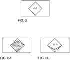
- Figure 5 shows an example of how numerical values can be integrated into the display.
- the value "+0.5" is displayed centrally on the polygonal base area of the pyramid (viewed from below), which here relates to the time difference which was achieved in the last lap driven compared to a predetermined best value on route 6 .
- a wide variety of numerical values, symbols or texts can be output.
- driving instruction symbols are generated analogously to the cases described above, in particular Figure 5 .
- the general pyramid symbol is shown tilted depending on the direction or speed change to be made.
- the display area 4a according to the in Figure 1C shown arrangement is positioned at the edge of the driver's field of vision, the representation must be as easy as possible and detectable from the corner of the eye. Therefore, a congruence of direction is used for the representation, that is, the position of the Driving instruction symbol within the display area 4a already shows - at least in broad outline - the content of the respective driving instruction.
- the driver should adjust the direction to the left ( Figure 7A ) or to the right ( Figure 7B ).
- the pyramid shown is tilted to the left or right accordingly.
- the axis of the tilt does not run in the middle of the display area 4a, but in such a way that the resulting representation of the tilted pyramid is in the left or right part of the display area 4a.
- the other area of the display area 4a is shown darkened, so that the user can also see at a glance that the information "left” or "right” is shown. This additional darkening is not necessary for the invention, but allows an additional amplification of the effect.
- a desired deceleration and acceleration can also be displayed, as in the Figures 7C and 7D shown.
- the pyramid is shown tilted downwards (deceleration) or upwards (acceleration) and the other area of the display area 4a is shown darkened.
- Figure 7E finally shows the top view of the base of the pyramid, as already described above for the base position of the pyramid.
- the display is centered on the display area 4a, since no directional information is to be transported and the edge areas on the right and left are darkened.
- a color and intensity curve can be displayed over the width of the display area 4a and clarify a driving instruction. For example, a "wave" of higher brightness in green color can run from left to right and thus represent an acceleration to the right. Conversely, a red color combined with a movement to the left can represent braking while turning the steering to the left. Furthermore, "waves" of higher brightness can run from the outside in, which can be used to represent a request for braking.
- Figure 8A shows a view of the route 16, further showing the actually traveled route 17 and the ideal line 18. This allows the user to recognize in a comparison mode at which points he has deviated from the ideal line 8 and to what extent. This representation can therefore be called up in particular when the vehicle 5 is not currently traveling, but a further journey is planned and improvements are to be made compared to the last journey.
- the in Figure 8B Display shown Information about the braking points 10 along the representation of the route 16.
- the ideal line 18 is shown in the example shown.
- points for the acceleration along the representation of the route 16 can also be specified in further exemplary embodiments.
- a comparison can be made with the braking and / or accelerations actually carried out, in that they are each displayed along the representation of the route 16 and the deviations from the optimum values, such as the position and intensity of the braking or acceleration processes, are indicated.
- the system according to the invention also has a configuration mode in which the user can make settings by entering data and / or selecting options for configuration.
- the user can select a color scheme. For example, display problems for color blind people can be avoided by choosing color pairs other than red / green, or by selecting certain hatchings or patterns.
- a "tutorial" menu is also provided, which the user can select in order to call up explanatory texts for individual functions of the system.
- a list of services stored for the route 6, for example lap times, can in particular be called up, so that the user can compare and classify his own service.
Landscapes
- Engineering & Computer Science (AREA)
- Transportation (AREA)
- Mechanical Engineering (AREA)
- Chemical & Material Sciences (AREA)
- Combustion & Propulsion (AREA)
- Automation & Control Theory (AREA)
- Human Computer Interaction (AREA)
- Navigation (AREA)
Claims (14)
- Procédé d'assistance à un utilisateur lors de la planification d'un parcours routier (6) et de l'exécution de celui-ci à l'aide d'un véhicule (5), dans lequel- des données sur le parcours routier (6) sont enregistrées,- des données optimales théoriques (8) d'au moins un paramètre pour l'exécution optimale du parcours routier (6) sont déterminées,- des données effectives (7) du paramètre pendant l'exécution du parcours routier (6) sont enregistrées et un écart entre les données effectives (7) et les données optimales (8) est déterminé,- en fonction de l'écart déterminé, une instruction de conduite est générée et- à l'aide de l'instruction de conduite, une représentation graphique d'un symbole d'instruction de conduite est générée et affichée sur une surface d'affichage (4a) d'un équipement utilisateur mobile (4),caractérisé en ce que
lors de la génération du symbole d'instruction de conduite, un angle de rotation autour d'au moins un axe est déterminé en fonction de l'instruction de conduite. - Procédé selon la revendication 1,
caractérisé en ce que
ledit au moins un paramètre comprend un paramètre de déplacement et/ou un paramètre de commande du véhicule, en particulier la position, la vitesse, l'accélération, l'actionnement de braquage et/ou l'actionnement de frein. - Procédé selon l'une quelconque des revendications précédentes,
caractérisé en ce que
le symbole d'instruction de conduite comprend une représentation tridimensionnelle d'un objet géométrique, en particulier d'une pyramide. - Procédé selon l'une quelconque des revendications précédentes,
caractérisé en ce que
le symbole d'instruction de conduite présente une conception colorée, qui est générée en fonction de l'instruction de conduite, le rouge représentant en particulier un ralentissement et le vert une accélération. - Procédé selon l'une quelconque des revendications précédentes,
caractérisé en ce que
une ligne idéale sur le parcours routier (6) est définie par les données optimales (8) et, lorsqu'un écart dans une direction par rapport à la ligne idéale est constaté à l'aide des données effectives (7), l'instruction de conduite est générée avec une composante de direction pour corriger la trajectoire suivie par intervention dans la direction du véhicule,
le symbole d'instruction de conduite présentant un axe longitudinal et l'axe longitudinal étant disposé en fonction de la composante de direction de l'instruction de conduite. - Procédé selon l'une quelconque des revendications précédentes,
caractérisé en ce que
la représentation graphique du symbole d'instruction de conduite présente une composante variable dans le temps, en particulier un clignotement et/ou un déplacement du symbole d'instruction de conduite. - Procédé selon l'une quelconque des revendications précédentes,
caractérisé en ce que
dans un mode de comparaison, en fonction de l'écart déterminé, une représentation comparative graphique avec une représentation spatiale du parcours routier (6) est générée et affichée sur la surface d'affichage (4a) de l'équipement utilisateur mobile (4). - Procédé selon la revendication 7,
caractérisé en ce que
la représentation comparative graphique comprend une superposition d'un profil optimal du paramètre (8) et d'un profil effectivement enregistré (7) du paramètre le long du parcours routier (6). - Procédé selon la revendication 7 ou 8,
caractérisé en ce que
la représentation spatiale du parcours routier (6) comprend au moins deux tronçons,
les tronçons sont générés en tant que segments sélectionnables de l'élément d'affichage et,
lorsqu'un segment est sélectionné, les données optimales (8) associées au segment sélectionné et les données effectives (7) relatives au tronçon sont affichées. - Procédé selon l'une quelconque des revendications précédentes,
caractérisé en ce que
dans un mode de configuration, des entrées de configuration de l'utilisateur sont enregistrées. - Procédé selon la revendication 10,
caractérisé en ce que
le symbole d'instruction de conduite présente une conception colorée qui est générée en fonction des entrées de configuration. - Système d'assistance à un utilisateur lors de la planification d'un parcours routier (6) et de l'exécution de celui-ci à l'aide d'un véhicule (5), présentant- une unité d'enregistrement (1), à l'aide de laquelle des données sur le parcours routier (6) peuvent être enregistrées et des données effectives (8) d'un paramètre pendant l'exécution du parcours routier (6) peuvent être enregistrées,- une unité de détermination (2), au moyen de laquelle des données optimales théoriques (8) d'au moins un paramètre pour l'exécution optimale du parcours routier (6) peuvent être déterminées,- une unité de commande (2), au moyen de laquelle un écart entre les données effectives (7) et les données optimales (8) peut être déterminé, une instruction de conduite pouvant être générée en fonction de l'écart déterminé et une représentation graphique d'un symbole d'instruction de conduite pouvant être générée à l'aide de l'instruction de conduite et- un équipement utilisateur mobile (4) présentant une surface d'affichage (4a), sur laquelle la représentation graphique peut être affichée,caractérisé en ce que
lors de la génération du symbole d'instruction de conduite, un angle de rotation autour d'au moins un axe peut être déterminé en fonction de l'instruction de conduite. - Système selon la revendication 12,
caractérisé en ce que
ledit au moins un paramètre comprend un paramètre de déplacement et/ou un paramètre de commande du véhicule, en particulier la position, la vitesse, l'accélération, l'actionnement de braquage et/ou l'actionnement de frein. - Procédé selon la revendication 12 ou 13,
caractérisé en ce que
la surface d'affichage (4a) dans le véhicule (5) est disposée au niveau du bord inférieur du champ de vision du conducteur, en particulier sur le tableau de bord derrière le volant.
Applications Claiming Priority (1)
| Application Number | Priority Date | Filing Date | Title |
|---|---|---|---|
| DE102015216817.4A DE102015216817A1 (de) | 2015-09-02 | 2015-09-02 | Verfahren und System zur Unterstützung eines Nutzers bei der Planung und Durchführung eines Befahrens einer Fahrstrecke mit einem Fahrzeug |
Publications (3)
| Publication Number | Publication Date |
|---|---|
| EP3138752A2 EP3138752A2 (fr) | 2017-03-08 |
| EP3138752A3 EP3138752A3 (fr) | 2017-03-22 |
| EP3138752B1 true EP3138752B1 (fr) | 2020-07-08 |
Family
ID=56740069
Family Applications (1)
| Application Number | Title | Priority Date | Filing Date |
|---|---|---|---|
| EP16182405.7A Active EP3138752B1 (fr) | 2015-09-02 | 2016-08-02 | Procede et systeme destines a assister un utilisateur lors de la planification et l'execution d'un parcours routier avec son vehicule |
Country Status (2)
| Country | Link |
|---|---|
| EP (1) | EP3138752B1 (fr) |
| DE (1) | DE102015216817A1 (fr) |
Cited By (2)
| Publication number | Priority date | Publication date | Assignee | Title |
|---|---|---|---|---|
| IT202100025037A1 (it) * | 2021-09-30 | 2023-03-30 | Ferrari Spa | Metodo di assistenza alla guida prestazionale di un veicolo stradale e relativo veicolo stradale |
| IT202100025022A1 (it) * | 2021-09-30 | 2023-03-30 | Ferrari Spa | Metodo di assistenza alla guida prestazionale di un veicolo stradale e relativo veicolo stradale |
Families Citing this family (7)
| Publication number | Priority date | Publication date | Assignee | Title |
|---|---|---|---|---|
| DE102017220486B4 (de) | 2017-11-16 | 2023-05-11 | Volkswagen Aktiengesellschaft | Verfahren zur Adaption einer vorbestimmten Referenzlinie für ein Kraftfahrzeug und Vorrichtung |
| US11710421B2 (en) * | 2018-12-05 | 2023-07-25 | Garmin Switzerland Gmbh | Driving analysis and instruction device |
| IT202000004891A1 (it) * | 2020-03-09 | 2021-09-09 | Ferrari Spa | Metodo di assistenza alla guida prestazionale di un veicolo stradale con interfaccia in realta' aumentata |
| CN116353617A (zh) * | 2021-12-28 | 2023-06-30 | 比亚迪股份有限公司 | 驾驶技能优化及评估的方法和车辆以及计算机存储介质 |
| IT202200004595A1 (it) * | 2022-03-10 | 2023-09-10 | Ferrari Spa | Metodo di competizione automobilistica per veicolo stradale, relativo apparato e relativo veicolo stradale |
| DE102022207194A1 (de) | 2022-07-14 | 2024-01-25 | Robert Bosch Gesellschaft mit beschränkter Haftung | Verfahren zum Betreiben eines Fahrzeugs, Vorrichtung und Fahrzeug |
| DE102022120936B4 (de) | 2022-08-18 | 2024-05-23 | Dr. Ing. H.C. F. Porsche Aktiengesellschaft | Verfahren zur Bereitstellung eines Auswertesystems |
Family Cites Families (8)
| Publication number | Priority date | Publication date | Assignee | Title |
|---|---|---|---|---|
| WO1999048073A1 (fr) * | 1998-03-19 | 1999-09-23 | Mannesmann Vdo Ag | Systeme de navigation traitant des evenements de la circulation |
| DE102005055744A1 (de) | 2005-11-23 | 2007-05-24 | Robert Bosch Gmbh | Fahrerassistenzsystem für Kraftfahrzeuge |
| US8275516B2 (en) * | 2009-07-21 | 2012-09-25 | Trimble Navigation Limited | Agricultural vehicle autopilot rollover risk assessment system |
| DE102010003985A1 (de) | 2010-01-04 | 2011-08-18 | Audi Ag, 85057 | Verfahren zum Betrieb eines Fahrerassistenzsystems eines Kraftfahrzeugs und Kraftfahrzeug |
| DE102011106358A1 (de) | 2011-07-02 | 2012-03-15 | Daimler Ag | Fahrerinformationssystem für einen Kraftwagen |
| DE102013000132B4 (de) * | 2013-01-05 | 2023-11-02 | Volkswagen Aktiengesellschaft | Verfahren und Vorrichtung zum Anzeigen von Informationen einer Funktionseinrichtung eines Fahrzeugs |
| EP2778007B1 (fr) * | 2013-03-12 | 2022-09-07 | INRIA - Institut National de Recherche en Informatique et en Automatique | Procédé et système pour évaluer le comportement de conduite anormale de véhicules se déplaçant sur une route |
| EP3048025A1 (fr) * | 2015-01-20 | 2016-07-27 | Harman Becker Automotive Systems GmbH | Système d'information de conducteur pour véhicules à deux roues |
-
2015
- 2015-09-02 DE DE102015216817.4A patent/DE102015216817A1/de not_active Ceased
-
2016
- 2016-08-02 EP EP16182405.7A patent/EP3138752B1/fr active Active
Non-Patent Citations (1)
| Title |
|---|
| None * |
Cited By (4)
| Publication number | Priority date | Publication date | Assignee | Title |
|---|---|---|---|---|
| IT202100025037A1 (it) * | 2021-09-30 | 2023-03-30 | Ferrari Spa | Metodo di assistenza alla guida prestazionale di un veicolo stradale e relativo veicolo stradale |
| IT202100025022A1 (it) * | 2021-09-30 | 2023-03-30 | Ferrari Spa | Metodo di assistenza alla guida prestazionale di un veicolo stradale e relativo veicolo stradale |
| EP4159516A1 (fr) * | 2021-09-30 | 2023-04-05 | FERRARI S.p.A. | Procédé d'assistance au conducteur améliorant la performance d'un véhicule routier et véhicule routier associé |
| EP4159568A1 (fr) * | 2021-09-30 | 2023-04-05 | FERRARI S.p.A. | Procédé d'assistance au conducteur améliorant la performance d'un véhicule routier et véhicule routier associé |
Also Published As
| Publication number | Publication date |
|---|---|
| DE102015216817A1 (de) | 2017-03-02 |
| EP3138752A3 (fr) | 2017-03-22 |
| EP3138752A2 (fr) | 2017-03-08 |
Similar Documents
| Publication | Publication Date | Title |
|---|---|---|
| EP3138752B1 (fr) | Procede et systeme destines a assister un utilisateur lors de la planification et l'execution d'un parcours routier avec son vehicule | |
| EP3931023B1 (fr) | Procédé pour faire fonctionner un système d'information du conducteur dans un égo-véhicule et système d'information du conducteur | |
| EP3931034B1 (fr) | Procédé pour faire fonctionner un système d'information du conducteur dans un égo-véhicule et système d'information du conducteur | |
| EP3931026B1 (fr) | Procédé pour faire fonctionner un système d'information du conducteur dans un égo-véhicule et système d'information du conducteur | |
| EP3931029B1 (fr) | Procédé pour faire fonctionner un système d'information du conducteur dans un égo-véhicule et système d'information du conducteur | |
| EP3931020B1 (fr) | Procédé pour faire fonctionner un système d'information du conducteur dans un égo-véhicule et système d'information du conducteur | |
| EP3931033B1 (fr) | Procédé servant à faire fonctionner un système d'information du conducteur dans un véhicule égo, et système d'information du conducteur | |
| EP3931028B1 (fr) | Procédé pour faire fonctionner un système d'information du conducteur dans un égo-véhicule et système d'information du conducteur | |
| EP3931027B1 (fr) | Procédé pour faire fonctionner un système d'information du conducteur dans un véhicule ego et système d'information du conducteur | |
| EP2944532B1 (fr) | Système d'assistance de feu de circulation pour un véhicule doté d'un dispositif d'affichage | |
| WO2019170387A1 (fr) | Incrustation d'informations additionnelles sur une unité d'affichage | |
| WO2019166222A1 (fr) | Procédé servant au calcul d'une incrustation à réalité augmentée d'informations supplémentaires pour un affichage sur une unité d'affichage, dispositif servant à mettre en œuvre le procédé, ainsi que véhicule automobile et programme informatique | |
| DE102018107515A1 (de) | Virtueller Lenkweg | |
| DE102016214916B4 (de) | Verfahren zum Betreiben eines Kraftfahrzeugs und Kraftfahrzeug | |
| EP3931024B1 (fr) | Procédé pour faire fonctionner un système d'information du conducteur dans un égo-véhicule et système d'information du conducteur | |
| EP3931030B1 (fr) | Procédé pour faire fonctionner un système d'information du conducteur dans un égo-véhicule et système d'information du conducteur | |
| DE102005048398B4 (de) | Assistenzsystem für den Fahrer eines Fahrzeugs, insbesondere eines Kraftfahrzeugs für den öffentlichen Straßenverkehr | |
| WO2012123007A1 (fr) | Procédé servant à fournir un affichage et dispositif de navigation | |
| EP3931025B1 (fr) | Procédé pour faire fonctionner un système d'information du conducteur dans un égo-véhicule et système d'information du conducteur | |
| DE102009005451B4 (de) | Verfahren zur Durchführung einer Versuchsfahrt eines Kraftfahrzeugs sowie Kraftfahrzeug hierfür | |
| DE102005059415A1 (de) | Spurwechselassistenzsystem für ein Fahrzeug | |
| DE102023107902A1 (de) | Verfahren und system zur unterstützung eines fahrers |
Legal Events
| Date | Code | Title | Description |
|---|---|---|---|
| PUAI | Public reference made under article 153(3) epc to a published international application that has entered the european phase |
Free format text: ORIGINAL CODE: 0009012 |
|
| STAA | Information on the status of an ep patent application or granted ep patent |
Free format text: STATUS: THE APPLICATION HAS BEEN PUBLISHED |
|
| PUAL | Search report despatched |
Free format text: ORIGINAL CODE: 0009013 |
|
| AK | Designated contracting states |
Kind code of ref document: A2 Designated state(s): AL AT BE BG CH CY CZ DE DK EE ES FI FR GB GR HR HU IE IS IT LI LT LU LV MC MK MT NL NO PL PT RO RS SE SI SK SM TR |
|
| AX | Request for extension of the european patent |
Extension state: BA ME |
|
| AK | Designated contracting states |
Kind code of ref document: A3 Designated state(s): AL AT BE BG CH CY CZ DE DK EE ES FI FR GB GR HR HU IE IS IT LI LT LU LV MC MK MT NL NO PL PT RO RS SE SI SK SM TR |
|
| AX | Request for extension of the european patent |
Extension state: BA ME |
|
| RIC1 | Information provided on ipc code assigned before grant |
Ipc: B60W 50/00 20060101ALI20170210BHEP Ipc: B60W 50/14 20120101AFI20170210BHEP |
|
| STAA | Information on the status of an ep patent application or granted ep patent |
Free format text: STATUS: REQUEST FOR EXAMINATION WAS MADE |
|
| 17P | Request for examination filed |
Effective date: 20170922 |
|
| RBV | Designated contracting states (corrected) |
Designated state(s): AL AT BE BG CH CY CZ DE DK EE ES FI FR GB GR HR HU IE IS IT LI LT LU LV MC MK MT NL NO PL PT RO RS SE SI SK SM TR |
|
| GRAP | Despatch of communication of intention to grant a patent |
Free format text: ORIGINAL CODE: EPIDOSNIGR1 |
|
| STAA | Information on the status of an ep patent application or granted ep patent |
Free format text: STATUS: GRANT OF PATENT IS INTENDED |
|
| INTG | Intention to grant announced |
Effective date: 20200128 |
|
| GRAS | Grant fee paid |
Free format text: ORIGINAL CODE: EPIDOSNIGR3 |
|
| GRAA | (expected) grant |
Free format text: ORIGINAL CODE: 0009210 |
|
| STAA | Information on the status of an ep patent application or granted ep patent |
Free format text: STATUS: THE PATENT HAS BEEN GRANTED |
|
| AK | Designated contracting states |
Kind code of ref document: B1 Designated state(s): AL AT BE BG CH CY CZ DE DK EE ES FI FR GB GR HR HU IE IS IT LI LT LU LV MC MK MT NL NO PL PT RO RS SE SI SK SM TR |
|
| REG | Reference to a national code |
Ref country code: CH Ref legal event code: EP Ref country code: AT Ref legal event code: REF Ref document number: 1288136 Country of ref document: AT Kind code of ref document: T Effective date: 20200715 |
|
| REG | Reference to a national code |
Ref country code: DE Ref legal event code: R096 Ref document number: 502016010425 Country of ref document: DE |
|
| REG | Reference to a national code |
Ref country code: IE Ref legal event code: FG4D Free format text: LANGUAGE OF EP DOCUMENT: GERMAN |
|
| REG | Reference to a national code |
Ref country code: LT Ref legal event code: MG4D |
|
| REG | Reference to a national code |
Ref country code: NL Ref legal event code: MP Effective date: 20200708 |
|
| PG25 | Lapsed in a contracting state [announced via postgrant information from national office to epo] |
Ref country code: LT Free format text: LAPSE BECAUSE OF FAILURE TO SUBMIT A TRANSLATION OF THE DESCRIPTION OR TO PAY THE FEE WITHIN THE PRESCRIBED TIME-LIMIT Effective date: 20200708 Ref country code: ES Free format text: LAPSE BECAUSE OF FAILURE TO SUBMIT A TRANSLATION OF THE DESCRIPTION OR TO PAY THE FEE WITHIN THE PRESCRIBED TIME-LIMIT Effective date: 20200708 Ref country code: PT Free format text: LAPSE BECAUSE OF FAILURE TO SUBMIT A TRANSLATION OF THE DESCRIPTION OR TO PAY THE FEE WITHIN THE PRESCRIBED TIME-LIMIT Effective date: 20201109 Ref country code: BG Free format text: LAPSE BECAUSE OF FAILURE TO SUBMIT A TRANSLATION OF THE DESCRIPTION OR TO PAY THE FEE WITHIN THE PRESCRIBED TIME-LIMIT Effective date: 20201008 Ref country code: SE Free format text: LAPSE BECAUSE OF FAILURE TO SUBMIT A TRANSLATION OF THE DESCRIPTION OR TO PAY THE FEE WITHIN THE PRESCRIBED TIME-LIMIT Effective date: 20200708 Ref country code: GR Free format text: LAPSE BECAUSE OF FAILURE TO SUBMIT A TRANSLATION OF THE DESCRIPTION OR TO PAY THE FEE WITHIN THE PRESCRIBED TIME-LIMIT Effective date: 20201009 Ref country code: HR Free format text: LAPSE BECAUSE OF FAILURE TO SUBMIT A TRANSLATION OF THE DESCRIPTION OR TO PAY THE FEE WITHIN THE PRESCRIBED TIME-LIMIT Effective date: 20200708 Ref country code: NO Free format text: LAPSE BECAUSE OF FAILURE TO SUBMIT A TRANSLATION OF THE DESCRIPTION OR TO PAY THE FEE WITHIN THE PRESCRIBED TIME-LIMIT Effective date: 20201008 Ref country code: FI Free format text: LAPSE BECAUSE OF FAILURE TO SUBMIT A TRANSLATION OF THE DESCRIPTION OR TO PAY THE FEE WITHIN THE PRESCRIBED TIME-LIMIT Effective date: 20200708 |
|
| PG25 | Lapsed in a contracting state [announced via postgrant information from national office to epo] |
Ref country code: RS Free format text: LAPSE BECAUSE OF FAILURE TO SUBMIT A TRANSLATION OF THE DESCRIPTION OR TO PAY THE FEE WITHIN THE PRESCRIBED TIME-LIMIT Effective date: 20200708 Ref country code: LV Free format text: LAPSE BECAUSE OF FAILURE TO SUBMIT A TRANSLATION OF THE DESCRIPTION OR TO PAY THE FEE WITHIN THE PRESCRIBED TIME-LIMIT Effective date: 20200708 Ref country code: PL Free format text: LAPSE BECAUSE OF FAILURE TO SUBMIT A TRANSLATION OF THE DESCRIPTION OR TO PAY THE FEE WITHIN THE PRESCRIBED TIME-LIMIT Effective date: 20200708 Ref country code: IS Free format text: LAPSE BECAUSE OF FAILURE TO SUBMIT A TRANSLATION OF THE DESCRIPTION OR TO PAY THE FEE WITHIN THE PRESCRIBED TIME-LIMIT Effective date: 20201108 |
|
| PG25 | Lapsed in a contracting state [announced via postgrant information from national office to epo] |
Ref country code: NL Free format text: LAPSE BECAUSE OF FAILURE TO SUBMIT A TRANSLATION OF THE DESCRIPTION OR TO PAY THE FEE WITHIN THE PRESCRIBED TIME-LIMIT Effective date: 20200708 |
|
| REG | Reference to a national code |
Ref country code: CH Ref legal event code: PL |
|
| REG | Reference to a national code |
Ref country code: DE Ref legal event code: R097 Ref document number: 502016010425 Country of ref document: DE |
|
| PG25 | Lapsed in a contracting state [announced via postgrant information from national office to epo] |
Ref country code: EE Free format text: LAPSE BECAUSE OF FAILURE TO SUBMIT A TRANSLATION OF THE DESCRIPTION OR TO PAY THE FEE WITHIN THE PRESCRIBED TIME-LIMIT Effective date: 20200708 Ref country code: IT Free format text: LAPSE BECAUSE OF FAILURE TO SUBMIT A TRANSLATION OF THE DESCRIPTION OR TO PAY THE FEE WITHIN THE PRESCRIBED TIME-LIMIT Effective date: 20200708 Ref country code: MC Free format text: LAPSE BECAUSE OF FAILURE TO SUBMIT A TRANSLATION OF THE DESCRIPTION OR TO PAY THE FEE WITHIN THE PRESCRIBED TIME-LIMIT Effective date: 20200708 Ref country code: LU Free format text: LAPSE BECAUSE OF NON-PAYMENT OF DUE FEES Effective date: 20200802 Ref country code: LI Free format text: LAPSE BECAUSE OF NON-PAYMENT OF DUE FEES Effective date: 20200831 Ref country code: CZ Free format text: LAPSE BECAUSE OF FAILURE TO SUBMIT A TRANSLATION OF THE DESCRIPTION OR TO PAY THE FEE WITHIN THE PRESCRIBED TIME-LIMIT Effective date: 20200708 Ref country code: DK Free format text: LAPSE BECAUSE OF FAILURE TO SUBMIT A TRANSLATION OF THE DESCRIPTION OR TO PAY THE FEE WITHIN THE PRESCRIBED TIME-LIMIT Effective date: 20200708 Ref country code: CH Free format text: LAPSE BECAUSE OF NON-PAYMENT OF DUE FEES Effective date: 20200831 Ref country code: SM Free format text: LAPSE BECAUSE OF FAILURE TO SUBMIT A TRANSLATION OF THE DESCRIPTION OR TO PAY THE FEE WITHIN THE PRESCRIBED TIME-LIMIT Effective date: 20200708 Ref country code: RO Free format text: LAPSE BECAUSE OF FAILURE TO SUBMIT A TRANSLATION OF THE DESCRIPTION OR TO PAY THE FEE WITHIN THE PRESCRIBED TIME-LIMIT Effective date: 20200708 |
|
| PLBE | No opposition filed within time limit |
Free format text: ORIGINAL CODE: 0009261 |
|
| STAA | Information on the status of an ep patent application or granted ep patent |
Free format text: STATUS: NO OPPOSITION FILED WITHIN TIME LIMIT |
|
| REG | Reference to a national code |
Ref country code: BE Ref legal event code: MM Effective date: 20200831 |
|
| PG25 | Lapsed in a contracting state [announced via postgrant information from national office to epo] |
Ref country code: AL Free format text: LAPSE BECAUSE OF FAILURE TO SUBMIT A TRANSLATION OF THE DESCRIPTION OR TO PAY THE FEE WITHIN THE PRESCRIBED TIME-LIMIT Effective date: 20200708 |
|
| 26N | No opposition filed |
Effective date: 20210409 |
|
| PG25 | Lapsed in a contracting state [announced via postgrant information from national office to epo] |
Ref country code: SK Free format text: LAPSE BECAUSE OF FAILURE TO SUBMIT A TRANSLATION OF THE DESCRIPTION OR TO PAY THE FEE WITHIN THE PRESCRIBED TIME-LIMIT Effective date: 20200708 |
|
| PG25 | Lapsed in a contracting state [announced via postgrant information from national office to epo] |
Ref country code: BE Free format text: LAPSE BECAUSE OF NON-PAYMENT OF DUE FEES Effective date: 20200831 Ref country code: IE Free format text: LAPSE BECAUSE OF NON-PAYMENT OF DUE FEES Effective date: 20200802 Ref country code: SI Free format text: LAPSE BECAUSE OF FAILURE TO SUBMIT A TRANSLATION OF THE DESCRIPTION OR TO PAY THE FEE WITHIN THE PRESCRIBED TIME-LIMIT Effective date: 20200708 |
|
| PG25 | Lapsed in a contracting state [announced via postgrant information from national office to epo] |
Ref country code: TR Free format text: LAPSE BECAUSE OF FAILURE TO SUBMIT A TRANSLATION OF THE DESCRIPTION OR TO PAY THE FEE WITHIN THE PRESCRIBED TIME-LIMIT Effective date: 20200708 Ref country code: MT Free format text: LAPSE BECAUSE OF FAILURE TO SUBMIT A TRANSLATION OF THE DESCRIPTION OR TO PAY THE FEE WITHIN THE PRESCRIBED TIME-LIMIT Effective date: 20200708 Ref country code: CY Free format text: LAPSE BECAUSE OF FAILURE TO SUBMIT A TRANSLATION OF THE DESCRIPTION OR TO PAY THE FEE WITHIN THE PRESCRIBED TIME-LIMIT Effective date: 20200708 |
|
| PG25 | Lapsed in a contracting state [announced via postgrant information from national office to epo] |
Ref country code: MK Free format text: LAPSE BECAUSE OF FAILURE TO SUBMIT A TRANSLATION OF THE DESCRIPTION OR TO PAY THE FEE WITHIN THE PRESCRIBED TIME-LIMIT Effective date: 20200708 |
|
| REG | Reference to a national code |
Ref country code: AT Ref legal event code: MM01 Ref document number: 1288136 Country of ref document: AT Kind code of ref document: T Effective date: 20210802 |
|
| PG25 | Lapsed in a contracting state [announced via postgrant information from national office to epo] |
Ref country code: AT Free format text: LAPSE BECAUSE OF NON-PAYMENT OF DUE FEES Effective date: 20210802 |
|
| P01 | Opt-out of the competence of the unified patent court (upc) registered |
Effective date: 20230523 |
|
| PGFP | Annual fee paid to national office [announced via postgrant information from national office to epo] |
Ref country code: DE Payment date: 20240831 Year of fee payment: 9 |
|
| PGFP | Annual fee paid to national office [announced via postgrant information from national office to epo] |
Ref country code: GB Payment date: 20240827 Year of fee payment: 9 |
|
| PGFP | Annual fee paid to national office [announced via postgrant information from national office to epo] |
Ref country code: FR Payment date: 20240826 Year of fee payment: 9 |
|
| REG | Reference to a national code |
Ref country code: DE Ref legal event code: R119 Ref document number: 502016010425 Country of ref document: DE |